

Page 1
Ceiling
mount
Wall
mount
25' (7.6 m)
max.
25' (7.6 m)
max.
ShatterPro 3
Glassbreak Detector
Installation Instructions
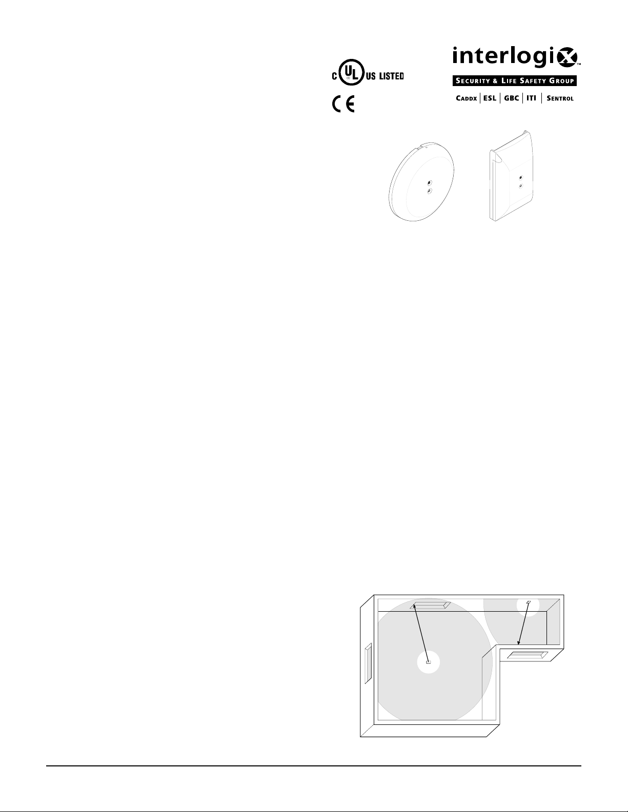
Description
The ShatterPro 3 is an acoustic glassbreak detector designed
to detect breaking glass from framed windows in the perimeter
of a building. The detector is mounted in the building interior
and uses a power supply from a 12VDC control panel. The
detector is available in either a low-profile round housing or a
rectangular housing that connects easily to a single-gang box.
Figure 1 - ShatterPro 3 Housings
Features
The detector provides the following features:
• Range up to 25 feet (7.6 m) Internal spring clip allows
optimized room size coverage.
• Alarm memory After an alarm and until power is cycled,
the alarm memory can be checked with the hand-clap test.
• LED indicator Red LED provides detector test and
status indication.
• T amper r esistant Provides a screw that secures the cover
to the base to prevent tampering.
• Hand-clap test In addition to a test mode, you can test the
detector by clapping your hands.
• Optional tamper switch Sends a signal to the control
panel when the cover is removed from the base.
What You Will Need
You need the following tools and parts to install the detector:
• ShatterPro 3 detector including screw to secure the cover
to the base
• Screws and wall anchors
• Flat-blade screwdriver
• Phillips screwdriver
• Sentrol 5709C hand-held tester
• Avoid locations where lined, insulating, or sound deadening drapes are used.
• Mount 12 inches (30.5 cm) away from wall corners.
• Avoid locations where interior closed wooden shutters are
used.
• Locate in a suitable envionment as follows:
- T emperature between 32° and 122°F (0° and 50°C)
- Humidity between 10 and 90% non-condensing
• Mount the detector on a stable surface up to 25 feet (7.6 m)
from the farthest point on the glass surface. See Figure 2.
• Avoid locations that expose the detector to possible false
alarm sources such as:
- Glass airlocks and vestibule areas
- Kitchens
- Residential car garages
- Small utility rooms
- Stairwells
- Bathrooms
- Small acoustically live rooms
- Air vents
Selecting a Location for the Detector
The detector can be mounted on ceilings or on walls opposite
or adjacent the window to be protected. See Figure 2.
Use the following guidelines to determine the best location to
install the detector.
• Mount at least 3 feet (1 m) from glass windows
being protected.
• Windows must be at least 12 x 24 inches
(30.5 x 61 cm) square.
ShatterPro 3 Glassbreak Detector
Figure 2 - Mounting Locations
1
Page 2
Selecting the Best Location for
gnitteS noitpircseD
nepOegnar(regraldnateeferauqs001smoorrofesU
tluafeD.))m6.7otm5.1(teef52ot5
desolCteeferauqs001nahtrellamssmoorrofesU
.))m3otm9.0(teef01ot3egnar(
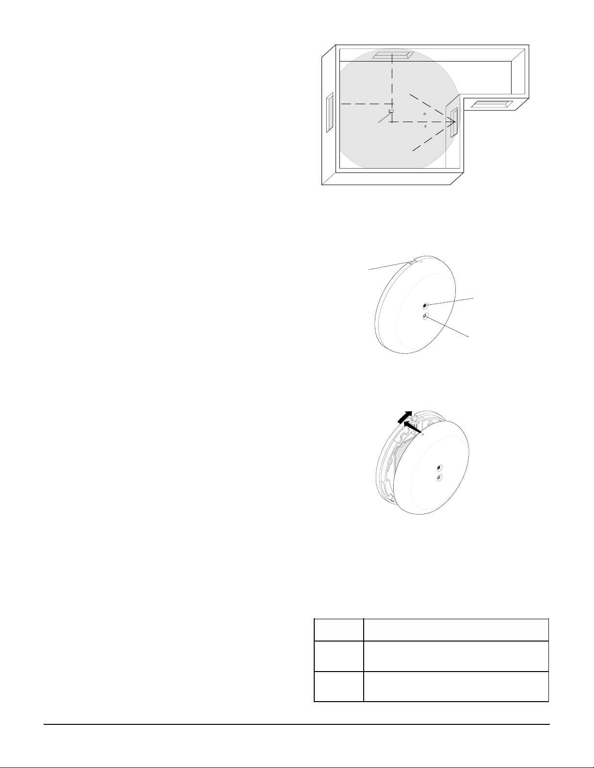
Multiple Window Coverage
The detector has a 360° coverage pattern that can be used to
cover several windows in a single room as follows:
Ceiling
mount
• Draw an imaginary line from the center of each window to
be covered in towards the center of the room.
• Mount the detector as close to where the lines intersect as
possible. See Figure 3.
• Do not mount the detector at more than a 60° angle from
the center of any window to be protected. See Figure 3.
Installing the Detector
All wiring must conform to the National Electric Code (NEC)
and/or local codes having jursidiction.
Important !
If you are unsure about a location, connect a 9V
battery to the detector and test it before permanently
mounting. See Testing the Detector.
Use the following steps to install the detector:
1. Run the security system wiring to the detector location.
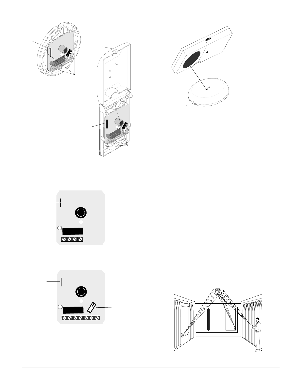
2. Remove the front cover as follows:
- Round housing Press the release tab on the lip of the
base, twist the cover counter clockwise, and lift off. See
Figure 4.
- Rectangle housing Insert a flat-blade screw driver into
the slot on the bottom of the cover and gently pry up to
unlock the cover. Grasp the bottom of the cover and lift up
until the cover latches in the open position. See Figure 6.
3. Set the range with J3 on the circuit board. See Setting
the Range.
4. Remove the appropriate wiring and mounting
knockout holes from the base. See Figure 6.
5. Pull the wires through the knockout holes and use two
screws to attach the base to the surface. Use wall anchors
if necessary.
6. Strip 3/8 inch of insulation from each wire.
7. Connect the system wires to the appropriate screw
terminals on the base and tighten the screws. See Figure 7.
8. Replace the cover as follows:
- Round housing Line up the tabs on the base with the
corresponding tabs on the cover, press together and turn
clockwise until the cover snaps firmly into place. See
Figure 5.
- Rectangle housing Press the cover back down over the
detector until the cover snaps firmly into place.
9. Apply power. The red LED should flash once.
10. Test the detector. See Testing the Detector.
Detector
Figure 3 - Multiple Window Coverage
Release tab
Figure 4 - Round Housing Parts
Figure 5 - Attaching the Cover
60 max.
60 max.
Microphone
LED
Setting the Range
The detector provides a spring clip (J3) to set room size. See
Figure 6. Use the following table to determine what setting to
use for an application.
2
ShatterPro 3 Glassbreak Detector
Page 3
•
S
in
g
l
e
•
C
o
n
t
i
n
u
o
u
s
P
la
t
e
•
T
e
m
p
e
r
e
d
•
L
a
m
in
a
te
d
•
Battery LED
B
a
tt
e
r
y
is
O
K
i
f
L
E
D
s
t
a
y
s
o
n
d
u
r
in
g
t
e
s
t
5
7
0
9
C
S
h
a
tt
e
r
S
e
r
ie
s
T
e
s
te
r
U
s
e
fo
r
t
e
s
t
in
g
:
S
h
a
t
t
e
r
P
r
o
S
h
a
tt
e
r
b
o
x
S
h
a
t
te
r
b
o
x
I
I
S
h
a
tt
e
r
S
w
i
tc
h
S
E
N
T
R
O
L
J3 Spring clip
Slot
Hold the tester so that the speaker is
within 1” of the detector microphone.
Knockouts
J3 Spring clip
Figure 6 - Detector Knockout Locations
J3 Spring clip
GND +12V N.C. COM
Models:
5812NT
R5812NT
J3 Spring clip
Knockouts
1” (2.54 cm)
When the detector is in test mode,
the LED lights steady for 4 seconds,
then flashes for 60 seconds. Time
resets after each valid test.
Figure 8 - Using the Tester
Testing the Detector
To verify detector range and operation, you need the Sentrol
5709C hand-held tester.
Use the following steps to test the detector:
1. Set the tester to the appropriate glass-type setting.
Use the tempered setting if you are unsure about the
glasstype.
2. Put the detector in test mode as follows:
- Hold the tester close to the detector. See Figure 8.
- Activate the tester.
The LED on the detector lights for 4 seconds and then
starts flashing to indicate the detector is in test mode. The
relay opens for 4 seconds, then returns to standby.
3. Hold the tester near the surface of the glass to be protected and aim the speaker at the detector. Be sure the
tester is at the point on the glass farthestfrom the detector.
If closed drapes or curtains are present, hold the tester
behind them. See Figure 9.
4. Press the test button on the tester. The LED on the
detector should stay on for 4 seconds to indicate the
glass is within detection range of the detector. If the
LED does not stay on for 4 seconds, move the detector
and retest.
GND +12V N.C. COM N.O. TAMP TAMP
Models:
5815NT
R5815NT
Figure 7 - Wiring Diagrams
ShatterPro 3 Glassbreak Detector
T amper Switch
Figure 9 - Testing the Range
3
Page 4

Understanding the LED
The red LED
the status of the unit as follows:
mralAssalggnikaerbnehwyalerhtiwsdnoces4rofnO
located on the front of the detector indicates
sutatS noitacidniDEL
norewoP.deilppasirewopnehwecnosehsalF
mralA/tsetpalC
yromem
ro
.demrala
.detcetedsi
edomtseT06rofsehsalfneht,yalerhtiwsdnoces4rofnO
.sdnoces
:tsetpalcehtotesnopsernI
.ylreporpgninoitcnufsidna
rewopsahrotcetedehtetacidnioteciwtsehsalF
sahrotcetedehtetacidniotsdnoces4rofnO
edomtsetehtsteserreggirttsethcaE.sdnoces
06rofgnihsalfrevostratsDELehtdnakcolc
Using the Hand-Clap Test and
Alarm Memory
The alarm memory and detector operation can be checked with
the hand-clap test as follows:
1. Standing under the detector, clap your hands together.
2. Observe the LED on the detector.
If the detector has power and is functioning properly, the LED
quickly flashes twice.
If the detector has alarmed, the LED will light for 4 seconds.
Cycle the power to clear the alarm memory .
The hand-clap test is intended as a functional test and is not an
accurate indication of detector range.
Maintaining the Detector
When installed and used properly, the detector provides years
of service with minimal maintenance. You should test the
detector annually to ensure proper operation.
Clean the cover with a damp (water) cloth as needed to keep it
free of dust and dirt. Always test the detector after cleaning.
Specifications
Input voltage ................................................... 9.5 to 16 VDC
Current
T ypical ...................................................................... 15mA
Maximum ................................................................... 25mA
Electrical configuration ................................ Form A, Form C
Relay rating................................................... 16V, 50mA max.
T amper switch rating .................................... 12V, 50mA max.
Detection range ......................... 3’ - 25’ (0.9 m - 7.6 m) x 360°
Alarm response............................................................ 4 sec.
Minimum glass size..................... 12” x 24” (30.5 cm x 61 cm)
Recommended glass thickness:
Plate......................................3/32” - 1/4” (2.4 mm - 6.4 mm)
Tempered ...............................1/8” - 1/4” (3.2 mm - 6.4 mm)
W ired............................................................. 1/4” (6.4 mm)
Laminated...................................................... 1/4” (6.4 mm)
Operating temperature ....................... 32° - 122° F (0° - 50°C)
Relative humidity ......................... 10 - 90% non-condensing
Round housing dimensions:
Depth ............................................................ 0.81” (2.1 cm)
Diameter ........................................................4.0” (10.2 cm)
Rectangle housing dimensions
Depth ............................................................ 0.81” (2.1 cm)
W idth ............................................................ 2.75” (7.0 cm)
Height ......................................................... 4.52” (11.5 cm)
Color ............................................................................White
Field wiring size .................................................. 18-24 AWG
Listing .......................................CUL, ULC-S306, UL 639, CE
FCC Compliance
This device complies with Part 15 of the FCC rules.
Operation is subject to the following two conditions:
(1) This device may not cause harmful interference.
(2) This device must accept any interference received,
including interference that may cause undesired operation.
Ordering
TN2185AmroF,gnisuohralugnatcerhtiw3orPrettahS
TN2185RAmroF,gnisuohdnuorhtiw3orPrettahS
TN5185 hctiwsrepmat,CmroF,gnisuohralugnatcerhtiw3orPrettahS
TN5185Rhctiwsrepmat,CmroF,gnisuohdnuorhtiw3orPrettahS
C9075retsetdleh-dnahkaerbssalG
4
rebmuNledoM noitpircseD
seirosseccA
ShatterPro 3 Glassbreak Detector
1030856 Rev D 12/00
 Loading...