

Page 1
POE303-EX-4P User Manual
original packing material, and use them again to repack the
Figure 1: POE303-MS
product in case there is a need to return it to us for repair.
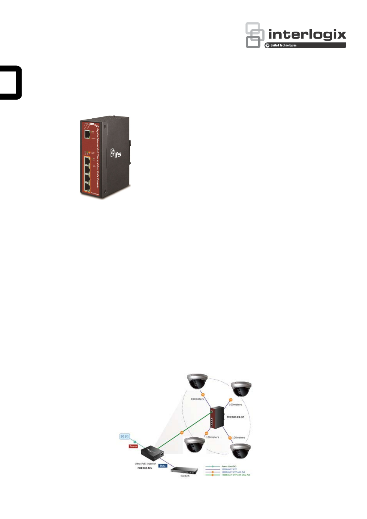
1.2 Application Diagram
The POE303-EX-4P is designed as the repeater to forward
both Gigabit Ethernet data and IEEE 802.3at PoE power, thus
extending the range of PoE installation. With just plug and play
and without additional power supply and setup, one single
POE303-MS can increase the PoE range to 200m and drive up
four remote PoE IP cameras or wireless access point.
See Figure 1.2 below.
1. Introduction
1.1 Packet Contents
Thank you for purchasing IFS POE303-EX-4P- 1-Port Ultra
PoE to 4-Port 802.3af/at Gigabit PoE Extender. Open the
box of the POE303-EX-4P and carefully unpack it. The box
should contain the following items:
Industrial Power over Ethernet Extender x 1
User Manual x 1
RJ45 Dust Cap x 5
Wall Mounting Kit x 1
If any of these are missing or damaged, please contact your
dealer immediately; if possible, retain the carton including the
Figure 1.2: Application Diagram
1.3 Key Features
Physical Port
5-port 10/100/1000BASE-T Gigabit RJ45 interface
- 1-port data + power input
- 4-port data + power output
Power over Ethernet
1-port data + power input
- Complies with ultra Power over Ethernet end-span
and mid-span PD
- Complies with IEEE 802.3at High Power over
Ethernet end-span / mid-span PD
- Supports PoE input pow er up to 60 W
4-port data + power output
- Complies with IEEE 802.3af / IEEE 802.3at Power
P/N 1073227 • REV A • ISS 12SEP16 1 / 6
Page 2

over Ethernet / end-span PSE
- Up to 4 IEEE 802.3af / 802.3at devices powered
- Supports PoE power up to 30.8 W for each PoE port
- Auto detects powered device (PD)
Extends the range of PoE to an additional 100 meters
(328ft.)
- Forwards both Ethernet data and PoE power to
remote device
Layer 2 Features
Hardware based 10/100Mbps, half / full duplex and
1000Mbps full duplex mode, flow control, auto-negotiation,
and auto MDI/MDI-X
Features Store-and-Forward mode with wire-speed
filtering and forwarding rates
IEEE 802.3x flow control for full duplex operation and back
pressure for half duplex operation
Integrates address look-up engine, supporting 8K absolute
MAC addresses
9K jumbo frame support in 1000Mbps duplex mode
Automatic address learning and address aging
Supports CSMA/CD Protocol.
Industrial Case / Installation
IP30 aluminum case protection
DIN rail and wall-mount design
Supports EFT protection for 6000 VDC power, and
6000 VDC Ethernet ESD protection
-40 to +75 °C operating temperature
No external power cable required for installation
Plug and Play installation
Standard Compliance
IEEE 802.3 10BASE-T
IEEE 802.3u 100BASE-TX
IEEE 802.3ab 1000BASE-T
IEEE 802.3x Flow Control
IEEE 802.3at High Power over Ethernet
IEEE 802.3af Power over Ethernet
FCC Part 15 Class A, CE
Note
:
PSE (Power Sourcing Equipment) is a device (switch, or hub
for instance) that provides power in a PoE setup. Maximum
allowed continuous output power per such device in IEEE
802.3af is 15.4W, and in IEEE 802.3 at is 30W.
PD (Powered Device) is a PoE-enabled terminal by PSE and
thus consumes ener gy , such as PoE IP Phones, PoE IP
cameras, PoE wireless access points, etc.
Do not connect PSE devices to the OUTPUT of the POE303EX-4P Extender as this may damage the unit.
1.4 Technical Specifications
Hardware Specifications
PoE In Port
1 x 10/100/1000BASE-T Ethernet with ultra
PoE “Data + DC” in, auto MDI/MDI-X, auto-
Network Connector
Switch Architecture Store-and-Forward switch architecture
MAC Address Table
Data Buffer 1Mbit
Switch Fabric 10Gbps
Switch Throughput 7.44Mpps @ 64Bytes
Flow Control
Jumbo Frame 9Kbytes
ESD Protection 6K VDC
EFT Protection 6K VDC
Enclosure IP30 aluminum metal case
Installation DIN rail kit and wall-mount ear
LED Display
Cable
Dimensions (W x D x
H)
Weight 715 g
Power Consumption
Power over Ethernet
PoE Standard
PoE Power
negotiation RJ45 connector
PoE Out Port
4 x 10/100/1000BASE-T Ethernet with IEEE
802.3af/at PoE “Data + DC” out, auto MDI/MDIX, auto-negotiation RJ 45 connector
8K MAC address table with auto learning
function
IEEE 802.3x pause frame for full duplex
Back pressure for half duplex
System: PWR (Green)
Power Input: Mid-span in (Green)
Power Input: End-span in (Green)
PoE Power Usage (%): 25 (Green)
PoE Power Usage (%): 50 (Green)
PoE Power Usage (%): 75 (Green)
PoE Input Port: LNK/ACT (Green)
PoE Input Port: PoE in (Orange)
Per PoE Output Port: LNK/ACT (Green)
Per PoE PoE-in-Use (Orange)
Twisted-pair cable:
10BASE-T: 2-pair UTP Cat. 3,4,5, up to
100 m
100BASE-TX: 2-pair UTP Cat. 5, 5e up to
100 m
1000BASE-T: 4-pair UTP Cat. 5e,6 up to
100 m
135 x 87.8 x 56 mm
60 W / 204.6BTU (Full loading with PoE
function)
PoE in Port
IEEE 802.3at High Power over Ethernet endspan / mid-span PD class 4 PD
Per PoE Out Port
IEEE 802.3at High Power over Ethernet endspan PSE
IEEE 802.3af Power over Ethernet end-span
PSE
PoE in Port
50 to 57 VDC, max. 60 W
2 / 6 P/N 1073227 • REV A • ISS 12SEP16
Page 3

Per PoE Out Port
Regulation Compliance
44 to 55 VDC, max. 30.8 W
PoE in Port
Power Pin Assignment
PoE Power Budget
Standards Conformance
Stability Testing
Standards Compliance
Environment
Operating
1/2(+), 3/6(-); 4/5(+), 7/8(-)
Per PoE out Port
1/2(+), 3/6(-)
50 W (max.) @ Ultra PoE input
20 W (max.) @ IEEE 802.3at PoE+ input
No support @ IEEE 802.3af PoE input
FCC Part 15 Class A, CE
IEC60068-2-32 (Free fall)
IEC60068-2-27 (Shock)
IEC60068-2-6 (Vibration)
IEEE 802.3 Ethernet
IEEE 802.3u Fast Ethernet
IEEE 802.3ab Gigabit Ethernet
IEEE 802.3x Flow Control
IEEE 802.3af Power over Ethernet
IEEE 802.3at High Power over Ethernet
Temperature: -40 to +75 °C
Relative Humidity: 5 to 95% (non-condensing)
2. Installation
2.1 Physical Dimensions
POE303-EX-4P 1-port Ultra PoE to 4-port 802. 3af /a t Giga bit
PoE Extender dimensions (W x D x H): 135 x 87.8 x 56 mm
Storage
Temperature: -40 to +85 °C
Relative Humidity: 5 to 95% (non-condensing)
1.5 Power over Ethernet Budget
The following table lists how many PoE devices can be
powered by POE303-EX-4P:
Power Source
IFS Ultra PoE
PSE
IEEE 802.3at
PoE+ PSE
IEEE 802.3af
PoE PSE
Remarks:
PoE Output
Budget*
50 W max.
20 W max.
10 W max.
Max. Number of PDs
supported
Class 4 PD @
25 W
Class 3
PD@15-watt
Class 2 PD @
7 W
Class 4 PD @
25 W
Class 3 PD @
15 W
Class 2 PD @
7 W
Class 2 PD @
7 W
2 units
3 units
4 units
0
1 unit
2 units
1 unit
2.2 Front Panel
Figure 2-1 shows the front panel of Industrial Power over
Ethernet Extender.
Figure 2-1: POE303-EX-4P Front Panel
1. The PoE Output Budget means the 4-port PD aggregated
power output. The aggregated power consumption will be
below 50 W if with Ultra PoE PSE.
2. Please check the power input LED (60 W PoE) for optimal
power output. Both mid-span and end-span LEDs should
be turned on for maximum capability.
P/N 1073227 • REV A • ISS 12SEP16 3 / 6
Page 4

System
LED Color Function
PWR Green
Midspan IN Green
Endspan
IN
PoE Input Port
LED Color Function
LNK/ACT Green
PoE In
Per PoE Output Port (Port 1 ~ 4)
LED Color Function
LNK/ACT Green
PoE In-Use Orange
PoE Power Usage (%) This in dica t or Is for indicatio n of
Green
Orange
Light to indicate POE303-EX-4P has
power.
Light to indicate POE303-EX-4P is
working in mid-span mode and offers up
to 30-watt power.
Light to indicate POE303-EX-4P is
working in end-span mode and offers up
to 30-watt power.
Light to indicate the port is linked up.
Blink to indicate that the POE303-EX-4P
is actively sending or receiving data over
that port.
Light to indicate POE303-EX-4P has
power.
Light to indicate the port is linked up.
Blink to indicate that the POE303-EX-4P
is actively sending or receiving data over
that port.
Light to indicate the port is providing
PoE power.
OFF to indicate the connected device is
not a PoE Powered Device (PD).
usage by % only.
LED Color Function
25 Green
50 Green
75 Green
Light to indicate the syst em is prov idin g
>25% PoE power usage.
Light to indicate the syst em is prov idin g
>50% PoE power usage.
Light to indicate the syst em is prov idin g
>75% PoE power usage.
Step 1: Lightly insert the bottom of the switch into the track.
Step 2: Check if the DIN rail is tightly on the track.
Please refer to the following procedures to remove the
Industrial Power over Ethernet Extender from the track.
Step 3: Lightly remove the DIN rail from the track.
2.3 Mounting Installation
This section describes how to install the Industrial Power over
Ethernet Extender and make c onne ctio ns to it. Please read the
following topics and perform the procedures in the order being
presented.
2.3.2 Wall-mounted Plate Mounting
To mount the Industrial Power over Ethernet Extender on the
wall, please follow the instructions described below.
Step 1: To remove the DIN rail from the Industrial Power over
Ethernet Extender, loosen the screws.
Note: In the installation steps below, this Manual uses
NS3503-16P-4C (IFS 16 Port Industrial Gigabit Switch) as an
example. However, the steps for IFSIFS Industrial Power over
Ethernet Extender are similar.
2.3.1 DIN-rail Mounting
Place the Industrial Power over Ethernet Extender on the DIN
rail, which is mounted on the wall, and screw it. Just follow the
steps below to install the Extender.
4 / 6 P/N 1073227 • REV A • ISS 12SEP16
Page 5

Step 2: Place the wall-mount plate on the rear panel of the
Industrial Power over Ethernet Extender.
Step 2: The PSE delivers both Ethernet Data and PoE power
over UTP cable to the POE303-EX-4P and the “PoE IN”
LED will be lit steadily.
Note
:
1. When the LED turns steady green, it means the POE303EX-4P is being powered successfully with PoE.
2. If the LED is not lit, please check the remote PSE or the
cable connecting to a PC or a network device to see if the
cable is correct. Or with an 802.3at device such as the
target PD, check whether the power injection is correct.
3. Never connect any non-standard POE PSE to the
POE303-EX-4P. It will damage the device permanently.
Step 3: Use the screws to screw the wall-mount plate on the
Industrial Power over Ethernet Extender.
Step 4: Use the hook holes in the corners of the wall-mount
plate to hang the Industrial Gigabit Ethernet Switch on the
wall.
Step 5: To remove the wall-mounted plate, reverse the steps
above.
2.4 Connecting POE303-EX-4P to Power Source Equipment (PSE)
This section describes how to install the Industrial Power over
Ethernet Extender and make connections to it. Please read the
following topics and perform the procedures in the order being
presented.
There are five RJ45 ports in the Industrial Power over Ethernet
Extender, of which the “PoE IN” port functions as "PoE (Data
and Power) input" and the ”PoE In-Use” port on the other
side functions as "PoE (Data and Power) output".
Step 1: Connect a standard CAT-5e/6 UTP cable from Power
Source Equipment (PSE), such as PoE Switch, PoE
injector hub and single port PoE injector, to the “PoE IN”
port of the POE303-EX-4P.
2.5 Connecting POE303-EX-4P to Powered
Device (PD)
Step 1: Connect the additional CAT-5e/6 cable that will be
used to connect to the remote Powered Device (PD) to
the “PoE In-Use” port of the POE303-EX-4P.
Step 2: The "PoE In-Use" port is also the power injector which
transmits DC voltage to the CAT-5e/6 cable and transfer
data and power simultaneously between the PSE and PD.
Step 3: Once the POE303-EX-4P detects the existence of an
IEEE 802.3at/af device, the “PoE In-Use” LED indicator
will be lit steadily, showing it is providing power.
:
Note
1. If the connected device is not fully complying with IEEE
802.3af/at standard or in-line power device, the PoE InUse LED indicator of the POE303-EX-4P will not be lit
steadily.
2. According to IEEE 802.3af/at standard, the POE303-EX4P will not inject power to the cable if not connecting to a
standard IEEE 802.3af/at device.
3. DO NOT connect any PSE to the OUTPUT ports 1~4 of
the POE303-EX-4P, it may damage the device
permanently.
P/N 1073227 • REV A • ISS 12SEP16 5 / 6
Page 6

Copyright
Manufacturer
FCC compliance
generates, uses, and can radiate radio frequency
quipment in a
FCC conditions
ACMA
compliance
Canada
CAN
Certification
European Union
directives
12004/108/EC (EMC directive): Hereby, UTC Fire
unsorted municipal waste in the European Union.
umentation
Trademarks and
patents
3. Customer Support
Thank you for purchasing IFS products. You can browse our
online FAQ resource and User’s Manual on IFS Web site first
to check if it could solve your issue. If you need more support
information, please contact IFS support team.
IFS online FAQ:
http://www.Interlogix.com
IFS support team mail address:
www.interlogix.com/support
Regulatory information
© 2016 United Technologies Corporation.
Interlogix is part of UTC Climate, Controls &
Security, a unit of United Technologies
Corporation. All rights reserved.
Interlogix.
2955 Red Hill Avenue, Costa Mesa, CA 92626
5923, USA
Authorized EU manufacturing representative:
UTC Fire & Security B.V.
Kelvinstraat 7, 6003 DH Weert, The Netherlands
Class A: This equipment has been tested and
found to comply with the limits for a Class A
digital device, pursuant to part 15 of the FCC
Rules. These limits are designed to provide
reasonable protection against harmful
interference when the equipment is operated in a
commercial environment. This equipment
2012/19/EU (WEEE directive): Products marked
with this symbol cannot be disposed of as
For proper recycling, return this product to your
local supplier upon the purchase of equivalent
new equipment, or dispose of it at designated
collection points. For more information see:
www.recyclethis.info.
2013/56/EU & 2006/66/EC (battery directi ve):
This product contains a battery that cannot be
disposed of as unsorted municipal waste in the
European Union. See the product doc
for specific battery information. The battery is
marked with this symbol, which may include
lettering to indicate cadmium (Cd), lead (Pb), or
mercury (Hg). For proper recycling, return the
battery to your supplier or to a designated
collection point. For more information see:
www.recyclethis.info.
The trade names used in this document may be
trademarks or registered trademarks of the
manufacturers or vendors of the respective
products.
Contact information
For contact information, see www.interlogix.com or
www.utcfssecurityproducts.eu.
energy and, if not installed and used in
accordance with the instruction manual, may
cause harmful interference to radio
communications. Operation of this e
residential area is likely to cause harmful
interference in which case the user will be
required to correct the interference at his own
expense.
This device complies with Part 15 of the FCC
Rules. Operation is subject to the following two
conditions:
(1) This device may not cause harmful
interference.
(2) This Device must accept any interference
received, including interference that may cause
undesired operation.
Notice! This is a Class A product. In a domestic
environment this product may cause radio
interference in which case the user may be
required to take adequate measures.
This Class A digital apparatus complies with
ICES-003 (A)/NMB-3 (A).
Cet appareil numérique de la classe A est
conforme à la norme CAN ICES-003 (A)/NMB-3
(A).
6 / 6 P/N 1073227 • REV A • ISS 12SEP16
& Security declares that this device is in
compliance with the essential requirements and
other relevant provisions of Directive
2004/108/EC.
 Loading...