

Page 1
SENTROL
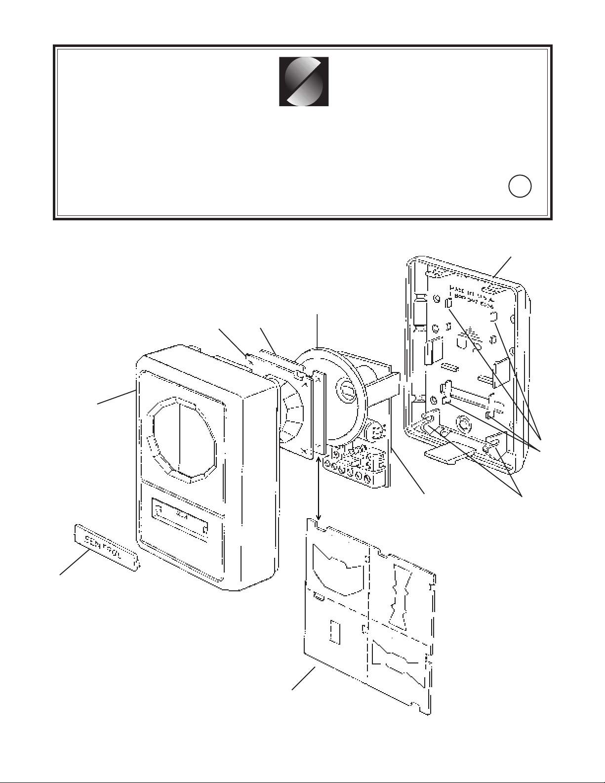
6250 Series SureShot PIR
Front cover
Lens
Installation Instructions
Models 6255, 6257
Pyro shield
Mask
U
L
LISTED
Back cover
Circuit
board
guides
Sliding
LED cover
Masking kit
WIDE
ANGLE
SPDT
Circuit
board
assembly
V
E
R
T
I
C
A
L
PET
ALLEY
ROTATE LENS
180
o
Cable
strain
reliefs
B
A
R
R
I
E
R
Page 2
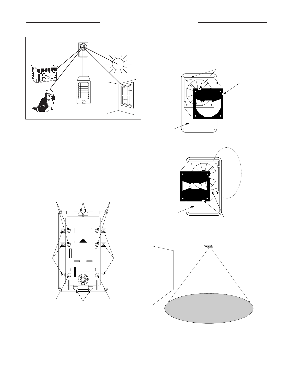
Avoid False Alarm Sources
Hot or cold air
directed onto sensor
INSTALLING THE SURESHOT
6. Choose which masking plate you need, if any. Insert
behind lens on front cover by pressing over four mounting
Sunlight or
reflected sunlight
pins. Once front cover is installed the masking plate will be
held tight against the lens.
Note: Masking plates have two notches to prevent
incorrect installation. One notch matches a rib
in the front cover. The second notch matches a
dimple in the lens.
Align notch
with dimple
Align notch
with rib
Pets
Intermittent
heat sources
For false-alarm-free operation, a PIR should not “see"
sources of heat or cold.
Mounting
1. Remove front cover by gently prying apart at bottom. Front
cover hinges at top.
2. Remove circuit board assembly by holding pyro shield and
pulling out of back cover.
3. Mount back cover to ceiling, wall or corner. For wall
mounting, make sure "up" arrow is pointing up. Use
appropriate mounting knockouts.
Knockouts for
Wall or Ceiling
Mounting
Wiring Knockouts
MADE IN U.S.A.
1-800-547-2556
Knockouts for
Wall or Ceiling
Mounting
WIDE
ANGLE
Inside of
Front Cover
Note: To correctly mount the Pet Alley Mask, the lens
must be removed from the front cover and
rotated 180
Inside of
Front Cover
o
.
PET
ALLEY
ROTATE LENS
o
180
Rotate
Lens 180°
Align notch
with dimple
7. Replace front cover.
Note: When mounting on the ceiling, align the unit to
maximize the oblong detection pattern for the room.
UP
Knockouts for
Corner Mounting
Knockouts for
Wall or Ceiling
Mounting
Wiring Knockouts
4. Snap circuit board assembly back into back cover by
aligning lower edge of board with circuit board guides and
pressing into place.
5. Connect wires per "wiring" diagrams on following page. A
wiring diagram is also included on the inside of the front
cover. You can strain relieve your wire cable by wrapping
it around the strain relief posts in the lower corners of the
back cover.
Knockouts for
Corner Mounting
Knockouts for
Wall or Ceiling
Mounting
Capture zone
at 8' (2.4m) mounting height
15'
(4.59m)
20' (6.12m)
8. After walk testing, the LED cover can be slid up to cover
the LED.
Note: Unit should be walktested monthly to ensure continual
Page 3

ZONE PATTERNS
T op View
0'
30'
9.14m
T op View
54°
38.4°
20°
0°
20°
54°
38.4°
40'
12.19m
With "Wide Angle" Mask
7'
2.13m
29 Zones
58 Beams
With "Vertical Barrier" MaskWall Mount–No Mask
7 Zones
14 Beams
Side View
T op View
Side View
+54°
+38.4°
+18°
0'
10°
40'
12.19m
With "Pet Alley" Mask
5.9°
10'
20'
30'
0'
3.04m
6.09m
9.14m
40'
12.19m
T op View
7'
2.13m
10'
3.04m
20'
6.09m
0'
Note: Lens must be
30'
40'
9.14m
12.19m
7 Zones
14 Beams
inverted for pet alley
18 Zones
36 Beams
0'
30'
9.14m
40'
12.19m
90°
3'
.91m
0'
Side View
10'
3.04m
6.09m
30'
9.14m
40'
12.19m
20'
0'
90°
Side View
7'
2.13m
30'
(9.14m)
40'
(12.19m)
10'
0'
3.04m
Ceiling Mount–No Mask
20'
6.09m
30'
9.14m
12.19m
29 Zones
40'
58 Beams
Capture
Zone
15' (4.59m) X 20' (6.12m)
capture zone
25' diameter (7.5m)
coverage pattern
Note: Intruder must enter capture zone in order to be detected. False alarm sources,
such as heaters, should be kept out of the coverage pattern.
With "Single Spot" Mask
8' (2.4m)
1 Zone
2 Beams
T op View
0'
10°
40'
12.19m
7'
2.13m
0'
Side View
10'
3.04m
20'
6.09m
30'
9.14m
40'
12.19m
7°
Wiring
Strip back the outer jacket on your wiring cable. This will
allow wires to flex in the case. Use cable strain relief built
into back cover to prevent stressing wires at their connection.
NC COM TAMP TAMP
POWER-IN
7 to 16 VDC
POWER-IN
7 to 16 VDC
+–
NC COM T/NO TAMP
+–
Note: The unit should be connected to a UL listed power
supply, capable of providing four hours of standby power.
6255 Model
6257 Model
Page 4
SURESHOT SPECIFICATIONS
FEA TURES
Pulse Count .........................Bi-directional, 1 zone (2 pulses)
with Motion Verification
Capture Zone (at 70˚ F)
Wide Angle (90˚) .......................30' (9.14m) x 30' (9.14m)
Single Spot ...................................... 40' (12.19m) range
Vertical Barrier ................................... 40' (12.19m) range
Pet Alley (90˚) ......................................30' (9.14m) range
360°Ceiling ......... 15' x 20' (4.57m x 6.10m) at 8' (2.44m)
mounting height
........16' x 30' (4.88m x 9.14m) at 12' (3.65m)
mounting height
...... Ceiling mounting height up to 12'(3.65m)
Mounting ............................................ Wall, corner , or ceiling
LED indicator .......................................................... Walktest
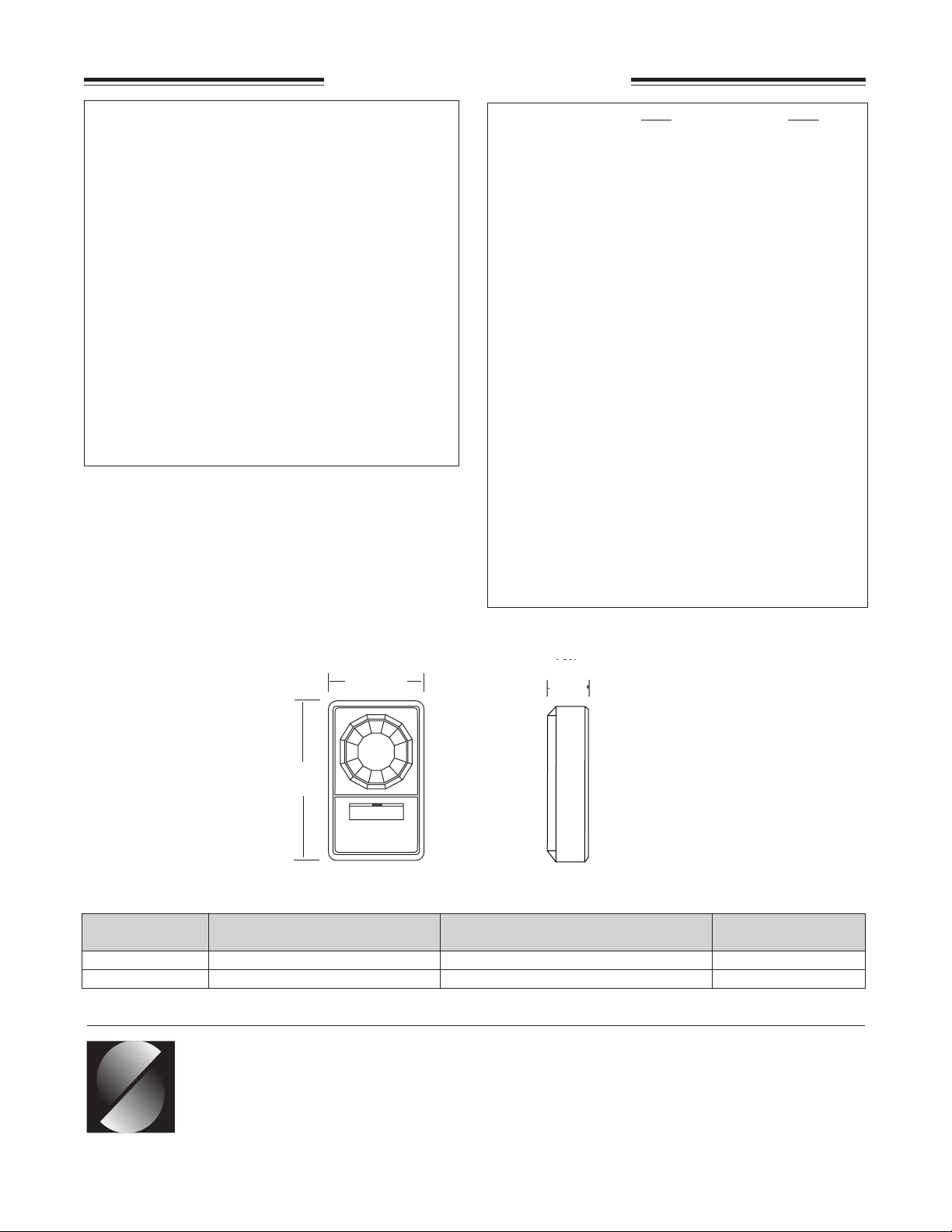
Size............................................................. 2.25"(5.72cm)W
3.75" (9.52cm)H
1.20" (3.05cm)D
Color ................................................................. White/White
6255 6257
ELECTRICAL
Voltage ................. 10 to 16 VDC ................ 7 t o 16 VDC
Current ................. 14mA typical, ................ 8mA typical,
20mA max. 10mA max
Max. relay rating... 16VDC, 50 mA ..............16VDC, 50 mA
Alarm output ...... Fail safe contacts ..........Fail safe contacts
w/10 ohms in series
Form A,........................ Form C,
Normally Closed (NC)... Normally Closed and
Open (SPDT)
Alarm duration ..... 2 to 5 seconds ............. 2 to 5 seconds
Cover tamper ..... Normally Closed, ......... Normally Closed,
contacts rating: 50 mA, 12VDC..rating: 50 mA, 12VDC
ENVIRONMENTAL
Operating T emp. .... 0°F to 120°F ................ 0°F to 120°F
(-17°C to +50°C).......... (-17°C to +50°C)
Humidity ................ 10% to 90% ................. 10% to 90%
noncondensing ............ noncondensing
RFI immunity.....greater than 20V/m ...... greater than 10V/m
from 0 to 1000MHz .......from 0 to 1000MHz
Static immunity............ 20KV .......................... 2.5KV
Lightning immunity ..... 2.4KV ,.......................... 2.5KV ,
1.2 joules max energy....2 joules max energy
impulse, impulse,
100 µsec duration .....1msec rise/50 msec
in field wiring decay
Front View
Front View
➝
2.25"
2.25”
➝
(5.72 cm)
(5.72cm)
Side View
1.20"
1.20"
(3.05cm)
(3.05 cm)
➝
3.75”
3.75"
(9.52 cm)
(9.52cm)
➝
PART LOOP ELECTRICAL LISTING
NUMBER TYPE CONFIGURATION
6255 Normally Closed N.C. UL
6257 Normally Closed or Open SPDT (N.C. and N.O.) UL
CORPORATE HEADQUARTERS
12345 SW Leveton Dr.
Tualatin, OR 97062
Tel.: 503.692.4052 Fax: 503.691.7566
U.S. & Canada: 800.547.2556
Technical Service: 800.648.7424
SENTROL
FaxBack: 800.483.2495
Sentrol reserves the right
to change specifications
without notice.
©1999 Sentrol
P-3172
14377 Rev A
 Loading...