

Page 1

TD-20, TD-200
System Setup
March 1997
DHA018940
Page 2

Warranties and Liabilities
The information and the software discussed in this document are subject to change without notice and
should not be considered commitments by Intergraph Corporation. Intergraph Corporation assumes no
responsibility for any errors in this document.
The software discussed in this document is furnished under a license and may be used or copied only in
accordance with the terms of the license. No responsibility is assumed by Intergraph for the use or
reliability of software on equipment that is not supplied by Intergraph or its affiliated companies.
All warranties given by Intergraph Corporation about equipment or software are set forth in your purchase
contract, and nothing stated in, or implied by, this document or its contents shall be considered or deemed a
modification or amendment of such warranties.
Copyright
1997, Intergraph Corporation including this documentation, and any software and its file formats and
audio-visual displays described herein; all rights reserved; may only be used pursuant to the applicable
software license agreement; contains confidential and proprietary information of Intergraph and/or other
third parties which is protected by copyright, trade secret and trademark law and may not be provided or
otherwise made available without prior written authorization.
Restricted Rights Legend
Use, duplication, or disclosure by the United States Government is subject to restrictions as set forth in
subdivision (c)(1)(ii) of the rights in technical data and computer software clause at DFARS 252.227-7013.
Unpublished rights reserved under the copyright laws of the United States.
Intergraph Corporation
Huntsville AL 35894-0001
Trademarks
Intergraph and the Intergraph logo are registered trademarks of Intergraph Corporation. TD and Intense
3D are trademarks of Intergraph Corporation.
Microsoft, MS-DOS, and Windows are registered trademarks of Microsoft Corporation. Windows
NT is a trademark of Microsoft Corporation.
Other brands and product names are trademarks of their respective owners.
Page 3

FCC Compliance
This equipment has been tested and found to comply with the limits for a Class B digital device, pursuant to
part 15 of the FCC Rules. These limits are designed to provide reasonable protection against harmful
interference when the equipment is operated in a residential installation. This equipment generates, uses,
and can radiate radio frequency energy. If the equipment is not installed and used in accordance with the
instructions, it may cause harmful interference to radio communications. However, there is no guarantee
that interference will not occur in a particular installation.
If this equipment does cause harmful interference to radio or television reception, which can be determined
by turning the equipment off and on, try to correct the interference as follows: re-orient or relocate the
affected device; increase the separation between this equipment and the affected device; connect this
equipment to an outlet on a circuit different from the circuit to which the affected device is connected;
consult a dealer or an experienced radio/television technician for help.
DOC Compliance
This digital apparatus does not exceed the Class B limits for radio noise emissions from digital apparatus
set out in the Radio Interference Regulations of the Canadian Department of Communications.
Warnings
Changes or modifications made to this device that are not approved by the party responsible for compliance
could void the user’s authority to operate the equipment.
To reduce the risk of electrical shock, do not attempt to open the device unless instructed. Do not use a tool
for purposes other than instructed.
There is a danger of explosion if the battery is incorrectly replaced. Replace the battery only with the same
or equivalent type as recommended by the manufacturer. Dispose of used batteries according to the
manufacturer’s instructions.
There are no user serviceable parts in the power supply. Refer all servicing of the power supply to qualified
service personnel.
To comply with FCC Class B limits, you must use shielded cables with this device.
Notes
This device is designed and manufactured to comply with approved safety standards for information
processing and business equipment.
Read all operating instructions before using this device. Keep these instructions for future reference.
Follow all warnings on the device or in the operating instructions.
Page 4

Declaration of Conformity
Manufacturer’s name: Intergraph Computer Systems
Manufacturer’s address: Huntsville Alabama USA 35894-0001
Manufacturer declares that the TD-20/TD-200 Office Automation Workstation, model number Sxxxxxxxx,
conforms to the following product specifications.
Safety: Low Voltage Directive 73/23/EEC
IEC950:1991/EN 60950 (1992)
UL1950 Second Edition, verified by Underwriter’s Laboratories (UL)
CAN/CSA C22.2 No. 950 Second Edition, verified by Canadian Standards Assocation (CSA)
EMC: EMC Directive 89/336/EEC
CISPR22:1985/EN55022 (Class B)
CFR47 Part 15 Subpart B (FCC Class B)
IEC 1000-4-2:1991 (Electrostatic Discharge Requirements)
IEC 1000-4-3:1994 (Radiated Electromagnetic Field Requirements)
IEC 1000-4-4:1984 (Electrical Fast Transient/Burst Requirements)
IEC 1000-4-5:1990 (Surge Immunity Requirements)
Date of declaration: October 1, 1996
Issued by:
Kenneth Gonzalez, Manager Mike Ellard, Senior Manager
Compliance Engineering Product Integration
Intergraph Computer Systems Intergraph Computer Systems
Phone 205-730-4265
This device complies with part 15 of the FCC Rules. Operation is subject to the following two conditions:
(1) This device may not cause harmful interference, and (2) this device must accept any interference
received, including interference that may cause undesired operation.
Approved by:
Page 5

Contents
Preface.............................................................................................................................vii
About This Document.....................................................................................................viii
Document Conventions...................................................................................................viii
Finding Operating System Information............................................................................. ix
Finding System Hardware Information............................................................................. ix
Learning About System Ergonomics.................................................................................. x
Getting Documentation and Training................................................................................. x
Getting Telephone Support ............................................................................................... xi
Using the Intergraph Bulletin Board Service .................................................................... xi
Using the Intergraph FAXLink.........................................................................................xii
Finding Intergraph on the Internet.................................................................................... xii
1 Setting Up the Hardware.............................................................................................. 1
Unpacking the System........................................................................................................ 1
Placing System Components.............................................................................................. 1
Connecting Cables.............................................................................................................. 2
TD-20................................................................................................................... 3
TD-200................................................................................................................. 4
Connecting to AC Power.................................................................................................... 4
Starting the System.............................................................................................................5
What Now? ........................................................................................................................5
v
2 Setting Up the Software................................................................................................ 7
Preparing for Setup ............................................................................................................7
Going Through Setup......................................................................................................... 9
Using the Welcome Dialog .............................................................................................. 10
Creating Backup Diskettes................................................................................. 10
Creating a Repair Disk or a Startup Diskette ..................................................... 11
Reviewing the System Introduction.................................................................... 11
What Now? ......................................................................................................................12
3 Configuring the System .............................................................................................. 13
Configuring the Video Display......................................................................................... 13
Installing Windows NT Service Pack Software (Intense 3D Pro Graphics) ...... 13
Configuring a Dual-Screen Display (G95 Graphics) ......................................... 14
Correcting Video Display Problems .................................................................. 15
Configuring the Sound Processor..................................................................................... 16
Configuring Networking...................................................................................................16
Configuring the PC Card Adapter.................................................................................... 16
Configuring the SCSI Adapter ......................................................................................... 17
Updating the Operating System........................................................................................ 17
Configuring the BIOS ...................................................................................................... 17
Page 6

vi
SCSI System BIOS.............................................................................................18
Updating the BIOS...........................................................................................................18
TD-20 BIOS.......................................................................................................18
TD-200 BIOS.....................................................................................................19
What Now?.......................................................................................................................21
4 Operating Notes...........................................................................................................23
Starting and Stopping the System.....................................................................................23
Observing Operating Precautions..................................................................................... 24
Updating a Repair Disk or a Startup Diskette................................................................... 24
Controlling Sound System Volume (TD-200)..................................................................24
Using the Audio Input Application (TD-200) ..................................................................25
Ensuring PC Card Support and Operation........................................................................ 25
Booting from an External SCSI Disk Drive......................................................................26
Restoring a Disabled COM2 Port..................................................................................... 26
5 Installing System Software .........................................................................................27
Before You Begin............................................................................................................. 27
Windows NT Workstation 4.0..........................................................................................28
Windows NT Workstation 3.51........................................................................................29
Windows 95......................................................................................................................30
Updating the Operating System........................................................................................32
6 Expanding the System................................................................................................. 33
Adding External Peripheral Devices.................................................................................33
Opening the Base Unit...................................................................................................... 34
Taking Antistatic Precautions........................................................................................... 34
Adding Expansion Boards................................................................................................ 35
TD-20 ICU......................................................................................................... 36
TD-200 ICU.......................................................................................................37
Adding System Memory................................................................................................... 38
Adding Internal Peripheral Devices.................................................................................. 40
Adding SCSI Peripheral Devices......................................................................................42
Using System Resources...................................................................................................42
ISA Bus Interrupt (IRQ) Assignments .............................................................. 43
Direct Memory Access (DMA) Channels .......................................................... 44
Input/Output (I/O) Addresses.............................................................................45
Index................................................................................................................................47
Returned Goods Authorization (RGA) Form
Warranty Procedure
Repair Depot Address Labels
Page 7

Preface
In its TD-20 and TD-200 personal computers, Intergraph Computer Systems offers the
precision quality of engineering workstations in Pentium and Pentium Pro processor-based
professional PCs. These systems are designed to be expanded and upgraded as requirements
intensify. As a complete solutions provider, Intergraph offers an expansive array of industry-
standard option cards and peripherals, all selected and certified to complement these system’s
capabilities. A range of graphics options enables you to tailor these systems to application
requirements ranging from office automation to 3D applications.
TD-20 and TD-200 systems provide the following features:
u
An ATX format mini-tower chassis
u
A Pentium (TD-20) or Pentium Pro (TD-200) processor with 256 KB cache
u
The Windows 95 operating system (TD-20) or the Windows NT Workstation (3.51 or
4.0) operating system (TD-20 and TD-200)
u
An Enhanced Integrated Device Electronics (EIDE) device controller or a Small
Computer System Interface (SCSI) device controller
vii
u
Peripheral Component Interconnect (PCI) bus
u
Plug and Play and Energy Star support
u
A range of video display adapters, including Intergraph’s G76, G95, and Intense 3D
u
An on-board Soundblaster 16-compatible sound processor
u
Enhanced Data Out (EDO) system memory expandable to 256 MB
u
A 3.5-inch EIDE floppy disk drive
u
An EIDE or SCSI hard disk drive
u
Seven full-length expansion slots -- three PCI, three Industry Standard Architecture (ISA),
and one shared
u
An optional 8x EIDE CD-ROM drive
u
An optional PC Card drive that supports two Type I or Type II PCMCIA devices, or one
Type III PCMCIA device
u
An optional microphone and speaker set
u
Optional network interface and SCSI adapters
u
Keyboard
Page 8

viii
About This Document
TD-20, TD-200 System Setup is organized as follows:
u
Chapter 1, “Setting Up the Hardware,” describes how to set up the system hardware.
u
Chapter 2, “Setting Up the Software,” describes how to set up the operating system and
associated system software.
u
Chapter 3, “Configuring the System,” describes how to configure the system for use.
u
Chapter 4, “Operating Notes,” provides information you will need when operating the
system.
u
Chapter 5, “Installing System Software,” provides information you will need if you must
re-install the operating system and associated system software.
u
Chapter 6, “Expanding the System,” provides information on expanding the system by
adding external and internal peripheral devices, expansion boards, and system memory.
Document Conventions
Bold
Commands, words, or characters that you key in literally.
Italic Variable values that you supply, or cross-references.
Monospace
SMALL CAPS Key names on the keyboard, such as D, ALT or F3; names of files and
Output displayed on the screen.
directories. You can type filenames and directory names in the dialog boxes
or the command line in lowercase unless directed otherwise.
CTRL+D Press a key while simultaneously pressing another key; for example, press
CTRL and D simultaneously.
Page 9

Finding Operating System Information
For more information on the Windows NT Workstation operating system, refer to the printed
and online Microsoft documentation delivered with the system:
u
For information on installing Windows NT Workstation, refer to Start Here (4.0) or to the
Installation Guide (3.51).
u
For information on using Windows NT Workstation 3.51, refer to the online System
Guide, delivered on the Windows NT software CD-ROM, and to online Help.
u
For information on using Windows NT Workstation 4.0, refer to Start Here and to online
Help.
For more information on the Windows 95 operating system, refer to the printed and online
Microsoft documentation delivered with the system:
u
For information on installing and using Windows 95, refer to Introducing Microsoft
Windows 95 and to online Help.
u
First-time users of Windows 95 can refer to Windows 95 Starts Here and Windows 95
How & Why, online presentations delivered on CD-ROM.
ix
Refer to the Late-Breaking News shipped with your system for important software and
documentation information not covered in this document.
Finding System Hardware Information
An online introduction to your new system is provided in the System Introduction, which
covers subjects such as the following:
u
System features
u
System controls and connections
u
Intergraph customer support
The System Introduction is a Windows Help 4.0 document. To view the System Introduction,
select System Introduction in the Welcome dialog that displays the first time you start the
system. You can also view the System Introduction by opening the
C:\WIN32APP\SYSINTRO directory on the system disk.
SYSINTRO.HLP file in the
Page 10

x
Detailed reference information for your new system is available in the System Board Manual,
which covers subjects such as the following:
u
System board connections and jumpers
u
System memory configuration and installation
u
BIOS Setup, parameters, and settings
The System Board Manual is delivered in the
C:\WIN32APP\SYSREF directory on the system
disk. The document is in Portable Document Format (PDF); to view it, use the Adobe
Acrobat Reader. A copy of the Adobe Acrobat Reader installer is included with the System
Board Manual. For more information, refer to the
README.TXT file delivered with the
document.
Documents covering expansion boards or optional hardware devices -- for example, the video
display adapter and the network adapter -- are delivered with the system. Refer to these
documents for more information on installing, configuring, and using an expansion board or
an optional hardware device.
Refer to the Late-Breaking News shipped with your system for important hardware and
documentation information not covered in this document.
Learning About System Ergonomics
Please read the Ergonomics Guide included with your Intergraph system. This document
provides valuable information on ways to minimize repetitive stress injuries for persons
working with a computer.
Getting Documentation and Training
You can purchase additional product documentation from Intergraph.
u
In the United States, contact your sales account representative, call the Intergraph Order
Desk at 1-800-543-1054, or send a fax to 1-800-548-3318 to place an order. If you call
or fax the Order Desk, have the document numbers ready for the items you wish to
purchase.
u
Outside the United States, contact the Intergraph subsidiary or distributor from which you
purchased your Intergraph product to place an order.
To find information on training for Intergraph products, or to enroll for an available class,
contact Intergraph Training Solutions at 1-800-240-3000.
Page 11

Getting Telephone Support
If you experience problems with your Intergraph product, or have questions about the
information in this document, you can contact Intergraph for help.
u
In the United States, call the Customer Response Center at 1-800-633-7248 between the
hours of 7:00 a.m. and 7:00 p.m. Central Time, Monday through Friday (except
holidays).
u
Outside the United States, contact the Intergraph subsidiary or distributor from which you
purchased your Intergraph product.
Have the following information readily available when you call:
u
The product’s serial number or your service/CPIN number.
u
The product’s name or model number.
u
Your name and telephone number.
u
A brief description of the question or problem.
xi
Using the Intergraph Bulletin Board Service
Available 24 hours a day, 7 days a week, the Intergraph Bulletin Board Service (IBBS) is an
electronic forum for Intergraph customers to exchange information with Intergraph's technical
and marketing staff, and with other Intergraph customers. You can use the IBBS to get
technical support information, documentation and training information, programs, and
software updates and fixes. The IBBS is also available for you to give suggestions, make
inquiries, and report problems.
To connect to the IBBS:
1. Set your system’s communications protocol for eight (8) data bits, no parity, one (1) stop
bit, and any baud rate up to 14,400.
2. Using a modem, dial the IBBS number, 1-205-730-8786. You can dial 1-205-730-6504 if
you are using a 2,400 baud connection.
Mirror sites are maintained for locations outside the United States. Information on these
sites is available on Intergraph Online, Intergraph’s World Wide Web server.
3. When connected, respond to the login request by keying in your user ID. If you have not
connected before, key in new to create a user ID.
Page 12

xii
4. Follow the menus to find what you need. If you are new to computer bulletin boards, the
IBBS provides clear choices and plenty of online help. A text file that explains IBBS
commands and organization is available for you to download.
If you have trouble connecting to or using the IBBS, log a support request through the
Customer Response Center (product entry IBBS), send a fax to 1-205-730-1110, or leave a
message for the System Operator (Sysop) at 1-205-730-1413.
Using the Intergraph FAXLink
You can use the Intergraph FAXLink to get technical support information by fax 24 hours a
day, 7 days a week. From a touch-tone phone or fax machine phone:
u
Call 1-800-240-4300 to get new user instructions, an index listing of available documents,
and an overview of the categories of available information.
u
Call 1-205-730-9000 to order the documents (up to 5 per call).
Follow the prompts provided to locate and deliver the information you need.
Finding Intergraph on the Internet
You can find Intergraph on the Internet in the following ways:
u
If you have a World Wide Web browser, connect to Intergraph Online, Intergraph’s
World Wide Web server, at http://www.intergraph.com. From the home page, follow
the links to Customer Services for information on available customer services and support
options.
u
If you have a File Transfer Protocol (FTP) program or a Gopher program, connect to
Intergraph at ftp.intergraph.com or gopher.intergraph.com.
u
You can get information from Intergraph’s email server at info@intergraph.com. Put
help in the body of the message (the subject line is ignored) to get information on such
subjects as Intergraph’s online services and where to get World Wide Web browsers.
u
You can participate in the Intergraph Customer Forum (ICF), a bidirectional gateway to
the USENET newsgroup comp.sys.intergraph. Anything posted to that group or sent to
comp-sys-intergraph@ingr.com is emailed to all subscribers. Incoming email messages
are also posted to the newsgroup. You can subscribe to the ICF via Intergraph Online.
Page 13

1 Setting Up the Hardware
Follow the instruction in this chapter to set up the hardware for your TD-20 or TD-200
system.
Unpacking the System
Remove everything from the shipping cartons, then look for the following items:
u
A monitor, with video cable, power cord, and documentation (if purchased from
Intergraph)
u
The system’s base unit and power cord
u
The system’s keyboard and mouse
u
Windows NT Workstation or Windows 95 operating system software (CD-ROM and
diskettes) and documentation
1
u
Intergraph system documentation
u
System software (diskettes) and documentation for expansion boards purchased from
Intergraph (which may include a video display adapter, a network adapter, a SCSI
adapter, and a PC Card slot adapter)
CAUTION Carefully remove the monitor and the base unit from their packaging. Do not let the monitor or
the base unit drop onto a hard surface, or damage to internal components may result.
NOTE If any of these items were not delivered, call the Customer Response Center immediately at 1-
800-633-7248.
Retain all packaging materials. If you return the system for repair, it must be in its original
packaging for you to obtain warranty service (if provided under your contract agreement).
Placing System Components
When placing the system’s components, follow these guidelines:
u
Move and place the monitor and the base unit carefully.
u
Place the base unit in a location where air can circulate freely around it. There should be
at least 3 inches of clearance in front of and in back of the base unit.
Page 14

2
u
Do not operate the base unit on its side.
u
Do not expose the system to high levels of dust, smoke, or moisture.
u
The location should maintain a temperature range of 10 °C (50 °F) to 26 °C (80 °F ); the
optimum operating temperature is 21 °C (70 °F ). The location should maintain a
humidity range of 20 percent to 80 percent non-condensing; the optimum humidity level
is 50 percent.
CAUTION Do not move the monitor or the base unit without first turning off power, or damage to internal
components may result.
Connecting Cables
Connect the following cables to their ports on the back panel of the base unit. Refer to the
figures on the following pages, and to the documentation delivered with any expansion boards
purchased from Intergraph, for connection details.
u
Keyboard cable to keyboard port (PS/2 type)
u
Mouse cable to mouse port (PS/2 type)
u
Video cable from monitor to video port on the installed video display adapter
u
Network cable to network port (on the optional network adapter board)
u
SCSI cable to SCSI port (on the optional SCSI adapter board)
u
Microphone cable to microphone port (on systems with an optional microphone)
u
On a TD-20 with optional speakers, speaker cable to speaker port
u
On a TD-200 with optional speakers, speaker cable to line out port; speaker power cable
from amplified speaker to speaker power port
All ports and cables are keyed or molded for proper cable connection. If a cable does not
connect easily, make sure you are aligning the cable connector correctly with the port.
CAUTION If you do not use cables supplied by Intergraph, use shielded cables to prevent excessive
electromagnetic interference (EMI). Intergraph cables are designed to reduce the amount of
EMI produced by the system.
NOTE The TD-20 uses non-powered (non-amplified) speakers; the TD-200 uses powered (amplified)
speakers. Ensure that you use the correct type of speakers for your system.
Page 15
Expansion boards reside in slots provided for Peripheral Component Interconnect (PCI) and
Industry Standard Architecture (ISA) boards. If you purchased any expansion boards from
Intergraph, they are installed in these slots as follows:
3
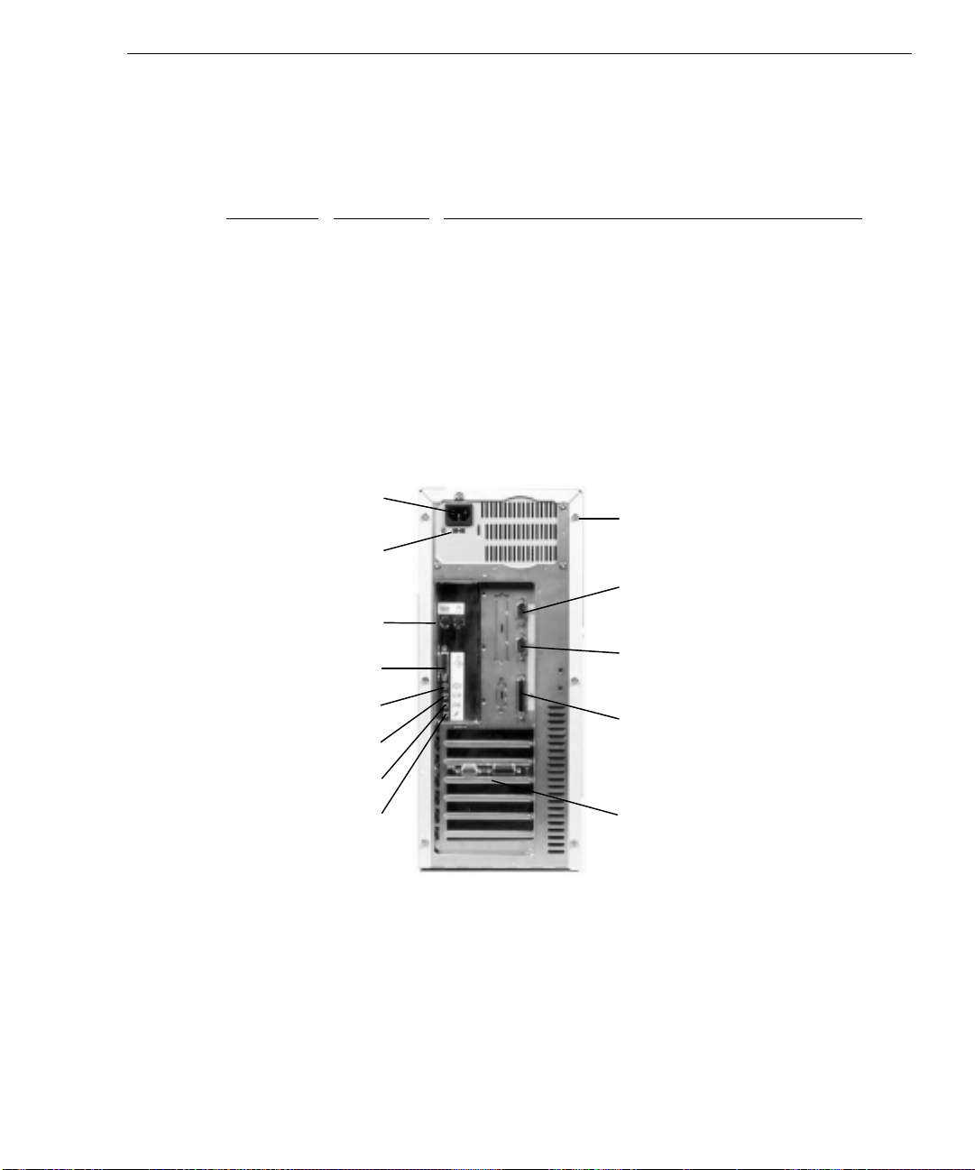
TD-20
Slot
Type Expansion Board
1 (Top) PCI SCSI adapter (optional)
2 PCI Video display adapter (optional; for G95 dual-screen)
3 PCI Video display adapter
4 PCI or ISA Network adapter (optional)
5 ISA 6 ISA PC Card adapter (optional; no external connection)
7 (Bottom) ISA -
AC Power Cord
AC Voltage Switch
90 - 132 V (right)
180 - 264 V (left)
Mouse (ri ght)
Keyboard (left)
Game/MIDI
Speakers
Line Out
Cover Screw
(one of six)
Serial Port
COM1
Serial Port
COM2
Parallel Port
LPT1
Line In
Microphone
Expansion
Board Slots
Page 16
4
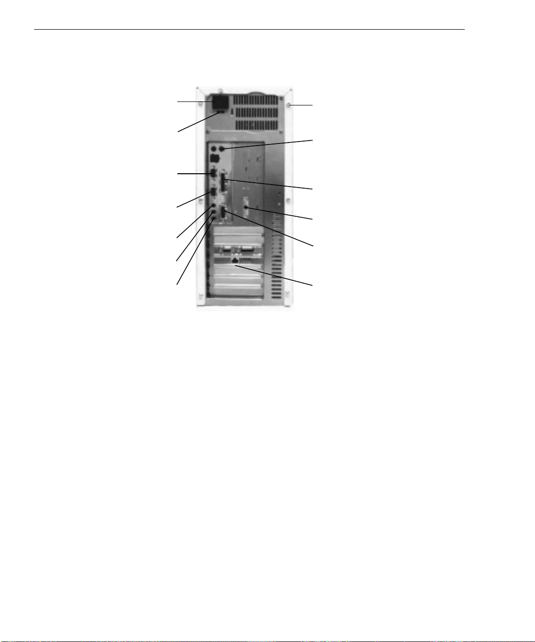
TD-200
AC Power Cord
AC Voltage Switch
90 - 132 V (r ight)
180 - 264 V (left)
Serial Port
COM2
Serial Port
COM1
Line Out
Line In
Microphone
Cover Screw
(one of six)
Mouse (right)
Keyboard (left)
Parallel Port
LPT1
Speaker Power
Game/MIDI
Expansion Board
Slots
Connecting to AC Power
WARNING Make sure the power switch on the front panel of the base unit is OFF (in the out
position). If the power switch is ON, serious equipment damage may result when you
plug the power cord into an AC outlet.
WARNING If you do not set the AC voltage switch correctly, serious equipment damage may result
when you turn on power to the system.
To connect the system to AC power:
1. Make sure that the AC voltage switch on the back panel of the base unit is set to the
proper line voltage for your location. Refer to the previous figures.
2. Connect the power cord to the back panel of the base unit, and then to a three-prong
grounded AC wall outlet. Refer to the previous figures.
Page 17
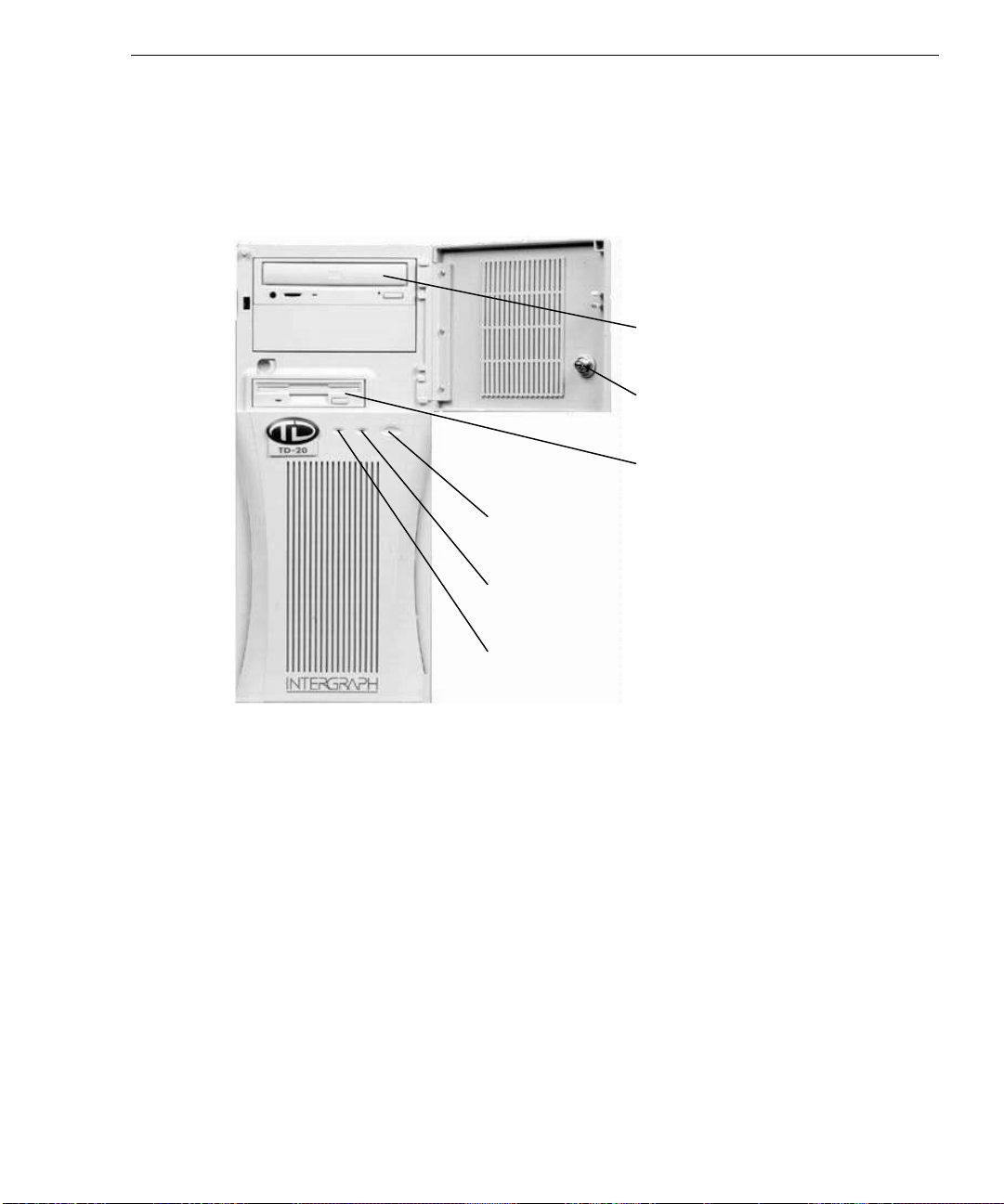
Starting the System
Press the power switches on the base unit and the monitor to turn on power to the system.
Refer to the following figure.
5
CD-ROM D rive
Door L o c k
Floppy Disk Drive
Power Switch
The system starts, and boots to a Setup screen or logon dialog for the operating system.
What Now?
Refer to Chapter 2, “Setting Up the Software,” for instructions on setting up the operating
system and associated system software.
Power On LED
Disk Access LED
Page 18

6
Page 19

2 Setting Up the Software
Follow the instructions in this chapter to set up the operating system and associated system
software on your TD-20 or TD-200 system.
Preparing for Setup
The operating system and associated system software are installed on the system’s hard disk.
Intergraph installed the following system software:
u
Driver software for the video display adapter
u
Driver software for the on-board sound processor
u
Operating system network software (TCP/IP and NetBEUI, if the network adapter is
installed)
u
Quick-Fix Engineering (QFE) update software -- fixes for operating system problems or
limitations on your Intergraph system (if any are needed)
7
u
The default File Allocation Table (FAT) file system.
The first time you start the system, it boots to a Setup screen or a logon dialog for the
operating system. If your system boots to a Setup screen, you follow the Setup process to
prepare the operating system -- Microsoft Windows NT Workstation or Microsoft Windows
95 -- for use.
Before you go through Setup, have the following documentation available:
u
Microsoft’s Installation Guide (Windows NT Workstation 3.51), Start Here (Windows
NT Workstation 4.0), or Welcome to Windows 95.
u
Documentation for expansion boards purchased from Intergraph (which may include a
video display adapter, a network adapter, a SCSI adapter, and a PC Card adapter).
Page 20

8
Get and record the following information:
u
Your name, and the name of your
company or organization:
u
For a system running Windows NT
Workstation, the CD Key from the
Windows NT Workstation CD case, or
the Product ID Number from Start
Here, the Installation Guide, or the
registration card:
u
For a system running Windows 95, the
Product ID Number from Welcome to
Windows 95 or the registration card:
u
A username and password for setting up
a user account.
If the system is connected to a network, get and record the following information from your
network administrator:
u
Computer name for your system:
u
Workgroup name (if the system will be
part of a workgroup):
u
Domain name (if the system will be part
of a Windows NT domain):
If the system is connected to a network that uses the Transmission Control Protocol/Internet
Protocol (TCP/IP), get and record the following TCP/IP networking information from your
network administrator:
u
Internet Protocol (IP) address for your
system:
u
IP subnet mask for your system:
u
IP domain name for your network:
u
IP address for your network’s default
gateway:
u
IP addresses for your network’s
Domain Name System (DNS) servers,
if any:
Page 21

Have several blank, formatted diskettes available to create backup diskettes containing system
software.
The Windows NT delivery media contain software and drivers for both Reduced Instruction
Set Computing (RISC)- and Intel-based systems. When installing Windows NT distribution
files, make sure to install them from the \
delivery media. For example, if you are installing a device driver from the Windows NT
CD-ROM, key in the following when asked for the path to the file, where drive is the drive
letter for the CD-ROM drive:
drive:\i386
Going Through Setup
On a system running Windows NT Workstation 4.0 or Windows 95, the first time you start the
system, it boots to a Setup screen. Select Next to start Setup, and follow the instructions
provided on-screen to complete the process. Take the default settings provided by Setup,
except as noted in the following text. You can set up a user account and join a workgroup or
domain after you configure the video display, the sound processor, and networking.
9
I386 directory (the Intel software directory) on the
On a system running Windows NT Workstation 4.0 or Windows 95:
u
Allow Setup to configure the network only if you have an installed network adapter, and
the system is connected to the network.
u
When prompted to create an Emergency Repair Disk (Windows NT Workstation) or a
Startup Diskette (Windows 95), do so.
u
If you do not set up a user account during Setup, press ENTER or select OK at the logon
dialog to log on to the operating system.
On a system running Windows NT Workstation 4.0:
u
The system’s hard disk drive contains Windows NT Workstation Setup files in the C:\I386
directory. When installing network or video display adapter drivers, you can refer to the
I386 directory when prompted for the location of Windows NT Workstation Setup files.
If you delete the
I386 directory from the system’s hard disk, you must have access to a
Windows NT Workstation CD-ROM to use Windows NT Workstation Setup files.
Page 22

10
On a system running Windows 95:
u
While Windows 95 files are being copied to the system, you are prompted for the
Windows 95 Setup Boot Diskette. This occurs even if the Windows 95 boot diskette is
already inserted in the floppy disk drive. Select OK to continue.
Next, you are notified that the MTMCDAI.SYS file could not be found on the Windows 95
Setup Boot Diskette. In the dialog that displays, specify that the file should be copied
from a:\, and then select OK.
u
The system’s hard disk drive contains Windows 95 Setup files in the
C:\WINDOWS\OPTIONS\CABS directory, as compressed .CAB files. When installing network
or video display adapter drivers, you can refer to the
the location of Windows 95 Setup files. If you delete the
CABS directory when prompted for
CABS directory from the
system’s hard disk, you must have access to a Windows 95 CD-ROM to use Windows 95
Setup files.
On a system running Windows NT Workstation 3.51:
u
The first time you start the system, it boots to a Welcome screen instead of a Setup
screen. Press
CTRL+ALT+DELETE to display the logon dialog, and press ENTER or select
OK to log on to Windows NT Workstation.
u
You can set up a user account and join a workgroup or domain after you configure the
video display, the sound processor, and networking.
For more information on Setup, and on using the interface features of the operating system,
refer to the operating system documentation and Help.
Using the Welcome Dialog
After going through Setup, a Welcome dialog displays. This dialog gives you easy access to a
few first-time startup tasks you should complete before proceeding.
Creating Backup Diskettes
Select Version Manager on the Welcome dialog to run the InterSite Version Manager utility.
Use this utility to create backup diskettes containing drivers and other system software
products that were installed on the system before shipment. You may need these backup
diskettes later -- for example, if you have to re-install a device driver or the operating system.
CAUTION If you do not use Version Manager to create backup diskettes for system software, you may
not be able to re-install critical system software or the operating system if needed.
Page 23

NOTE You may not have to create backup diskettes for system software. If Version Manager does
not list drivers or other system software products, they are available on the operating system
software CD-ROM or on backup diskettes delivered with expansion boards.
If the system requires Quick-Fix Engineering (QFE) update software, it is included in the
system software available for backup diskette creation. QFE update software contains fixes
for operating system problems or limitations on your Intergraph system, and is only shipped
with the system if it is needed. If QFE update software is shipped with the system, you should
create a QFE backup diskette for use if you have to re-install the operating system.
Refer to Version Manager Help for information on creating Intergraph system software and
other diskettes. Check the Intergraph Bulletin Board Service (IBBS) and vendor bulletin
boards frequently for new and updated drivers.
Creating a Repair Disk or a Startup Diskette
If you did not create an Emergency Repair Disk (Windows NT Workstation) or a Startup
Diskette (Windows 95) during Setup, select Repair Disk on the Welcome dialog to create the
appropriate diskette. The files on these diskettes can restore the original contents of a
damaged Registry (that is, at the time the operating system was installed), along with the
standard operating system drivers. You should also update a Repair Disk or a Startup Diskette
after you finish configuring the system.
11
Refer to the operating system documentation and Help for information on creating a Repair
Disk or a Startup Diskette.
Reviewing the
System Introduction
Select System Introduction on the Welcome dialog to display the System Introduction. This
document is an online introduction to your new system in Windows Help 4.0 format, covering
such subjects as system features, system controls and connections, and Intergraph customer
support. Review the information in the System Introduction to become more familiar with
your system.
NOTE You can also view the
C:\WIN32APP\SYSINTRO directory on the system disk. You may want to link the SYSINTRO.HLP file
to an icon, a shortcut, or a system menu to make it easier to display.
System Introduction
by opening the SYSINTRO.HLP file in the
Page 24

12
What Now?
Refer to Chapter 3, “Configuring the System,” to configure the system for use.
Refer to the online System Introduction for information on system features and controls.
Page 25

3 Configuring the System
Follow the instructions in this chapter to configure your Intergraph TD-20 or TD-200 system
for use.
Configuring the Video Display
The first time you start the system, it uses the installed video display adapter running at
standard VGA resolution (640 x 480) to run the video display. For the system to use the
installed video display adapter at other display resolutions, you must configure the video
display driver. On systems running Windows NT Workstation 4.0 and Windows 95, you can
do this during first-time setup.
To configure the video display, open Display in the Control Panel. Use the Display Properties
dialog (Windows NT Workstation 4.0 and Windows 95) or the Display Settings dialog
(Windows NT Workstation 3.51) to configure the video display.
13
Refer to the documentation and
adapter and driver for detailed configuration instructions. Refer to the operating system
documentation and Help for information on using the Display Properties or Display Settings
dialog.
README.TXT files accompanying the installed video display
Installing Windows NT Service Pack Software (Intense 3D Pro Graphics)
On a TD-200 system with Intense 3D Pro graphics running Windows NT Workstation 3.51,
you must install Windows NT Workstation 3.51 Service Pack 4 software. Service Pack 4
software is available on the Microsoft Service Pack 4 CD-ROM delivered with the system.
Refer to the
NOTE You cannot remove an installed Service Pack. To return your system to its original
configuration, you must re-install Windows NT Workstation 3.51.
CAUTION Installing Service Pack 4 may affect removal of installed Intergraph software products.
Microsoft has provided a fix for this, and Intergraph has included this fix in the Quick-Fix
Engineering (QFE) update software delivered with the system.
README.TXT file on the Service Pack 4 CD-ROM for more information.
Page 26

14
Configuring a Dual-Screen Display (G95 Graphics)
On a system set up for dual-screen G95 graphics (using two G95 video display adapters), the
video display driver treats the combined display area of both screens as a single canvas that
covers both screens. In this Full Canvas style, windows centered on the canvas are split
between the two screens. This includes most system dialog boxes.
Under Windows NT Workstation 3.51, the G95 video display driver can treat the left or top
monitor as the primary screen, while a full desktop extends across both screens. In this
Primary Top/Left style, some windowing behaviors may be unexpected. For example, dialogs
display fully and applications maximize on the primary screen; toolbars may not use the entire
desktop; and screen savers may work only on the primary screen.
NOTE The Primary Left/Top dual-screen style is not available in Windows NT Workstation 4.0.
To change the dual-screen style under Windows NT Workstation 3.51, you must edit the
Windows NT Registry.
WARNING Be careful when making changes to the Registry. Any mistakes or incorrect changes
may cause serious operating system problems, and you may have to re-install Windows
NT. If the system becomes unusable after you have changed the Registry, you may be
able to restart the system and use the Last Known Good configuration option to undo
the changes. Refer to Windows NT documentation for more information on the Last
Known Good configuration option.
To change the dual-screen style:
1. Start the Registry Editor (
REGEDT32.EXE) to open the Registry.
2. Open the following subkey in the Registry:
HKEY_LOCAL_MACHINE\SYSTEM\CurrentControlSet\Services\mgax64\
Device0
3. In the right-hand pane of the Registry Editor Window, select User.Center.Dialogs.
4. From the Edit menu, select DWORD.
5. To enable Primary Top/Left style, type 0 into the Data box. To enable Full Canvas style,
type 1 into the Data box.
6. Select OK.
7. Exit from the Registry Editor.
8. Restart the system.
Page 27

Correcting Video Display Problems
If the system’s video display is black, not synchronized, or distorted after you restart the
system, you may have a video configuration problem. You may be able to correct the problem
by restarting the system in VGA mode. On a system running Windows NT, you may also be
able to correct the problem by using the Last Known Good option to return the system to the
last known good configuration recorded by Windows NT.
To use the Windows NT Last Known Good option:
1. Power down and restart the system.
2. When prompted to display the Last Known Good menu, press the space bar.
3. If using the Last Known Good option fails to correct the video display problems, you can
obtain a functional video resolution by restarting the system in VGA mode.
To restart the system in VGA mode:
1. Power down and restart the system.
2. At the boot screen, select the VGA mode option appropriate for your system.
Check for the following common configuration problems and solutions.
15
u
A multi-sync monitor is connected to the system, but a multi-sync monitor type is not
selected, and the display driver cannot determine this by querying the monitor. Select an
appropriate multi-sync monitor type.
u
A selected resolution, depth, or refresh rate is not supported by the multi-sync monitor.
Try using different video display settings.
u
The Dual Screen option is selected, but only one video display adapter is detected. Clear
the Dual Screen option.
u
A multi-sync monitor is selected, but a monitor with different video timings (such as an
Intergraph InterVue monitor) is connected to the system. Select the appropriate monitor
type.
u
The monitor selection is inappropriate for the multi-sync monitor attached to the system.
Restart the system in VGA mode, and then select a new monitor.
u
A graphics resolution and color depth has been selected that exceeds installed display
memory. Restart the system in VGA mode, then open Display in the Control Panel to reinstall and configure the display driver as described in the video display adapter
documentation delivered with the system.
Restart the system and select the non-VGA version of the appropriate operating system to use
the reconfigured video display driver.
Page 28

16
Configuring the Sound Processor
The system is equipped with an on-board sound processor whose driver requires no
configuration. If the system has a microphone and speakers, you can use the operating
system’s sound control programs to control them. Additional accessories for the on-board
sound processor are available from the Intergraph Bulletin Board Service (IBBS) or from
vendor bulletin boards pointed to by the IBBS.
NOTE TD-20 and TD-200 systems have different sound processors and require different sound
processor drivers. TD-20 systems use the Sound Blaster driver; TD-200 systems use the
Crystal Audio driver.
Refer to the operating system documentation and Help for information on using sound control
programs.
Configuring Networking
If you purchased an optional network adapter, it was installed before shipment. You must
configure the operating system to use the network adapter. To do this, you may have to install
network driver software and network adapter control software, and then change operating
system settings to enable networking. Before you do this, make sure the network adapter is
connected to the network.
To configure networking, open Network in the Control Panel. Follow the instructions in the
dialogs to set up the system to use a network. Be sure to set up the appropriate network
protocols, such as Transmission Control Protocol/Internet Protocol (TCP/IP) and NetBIOS
Extended User Interface (NetBEUI), for the network to which your system is connected.
Refer to the documentation for the installed network adapter for detailed configuration
instructions. Refer to the operating system documentation and Help for information on setting
up the system to use a network.
Configuring the PC Card Adapter
If you purchased the optional PC Card adapter, it was installed before shipment, along with its
driver software. No configuration is required.
Refer to Chapter 4, “Operating Notes,” Chapter 6, “Expanding the System, “ and the operating
system documentation and Help for information on using PC Card devices.
Page 29

Configuring the SCSI Adapter
If you purchased the optional SCSI adapter, it was installed before shipment. You must install
the driver software for the adapter to use it. You may have to change system BIOS settings
and operating system settings to use SCSI devices attached to the adapter.
Refer to the documentation delivered with the SCSI adapter for detailed configuration
instructions. Refer to Chapter 6, “Expanding the System,” for information on adding SCSI
devices to the system. Refer to the operating system documentation and Help for information
on using SCSI peripherals.
Updating the Operating System
Microsoft Service Packs contain the latest improvements and system fixes for Microsoft
operating systems. Service Packs are created by Microsoft for post-release support. You can
obtain Service Packs from Microsoft’s World Wide Web and FTP sites free of charge.
CAUTION If Intergraph provides a Service Pack through the IBBS or with a product or system, it has
been certified against Intergraph hardware as described in the announcement of its
availability. If you obtain a Service Pack from any other source, be aware that it may not be
certified against your Intergraph hardware.
17
Configuring the BIOS
Your system’s basic input/output system (BIOS) records basic system operating parameters,
such as the amount of memory, the boot sequence, and the type of video display. The
system’s operating parameters are set in the BIOS before shipment, and you should not need
to change them immediately. However, you may want to configure some aspects of system
operation later by changing BIOS settings. To do this, you use the BIOS Setup utility.
The BIOS is stored in flash erasable-programmable memory (EPROM) on the system board,
and reads the system parameters in the system’s complementary metal-oxide semiconductor
(CMOS) random-access memory (RAM). When you turn off power to the system, a battery
provides power to CMOS RAM, which retains the system parameters. Each time you turn on
system power, the BIOS uses the stored parameters to configure the system.
To run the BIOS Setup program:
1. Restart the system.
2. When the BIOS version displays on screen, press
F2 (on a TD-20) or F1 (on a TD-200).
Page 30

18
Refer to the appropriate System Board Manual for information on using BIOS Setup.
SCSI System BIOS
On a system equipped with a Small Computer System Interface (SCSI) adapter and internal
SCSI hard disk drives, the BIOS is configured to boot from and use the SCSI disk drives. If
you update the BIOS or reset the BIOS configuration, make sure the appropriate BIOS
parameters are set correctly for a SCSI system.
TD-20 BIOS
In BIOS Setup, on the Advanced screen, set Integrated PCI IDE to Primary.
TD-200 BIOS
If you have a version of the BIOS previous to 01.00.11.CS1, do the following in BIOS Setup:
u
On the Advanced/Plug and Play Configuration screen, set Configuration Mode to Use
ICU.
u
On the Advanced/Plug and Play Configuration screen, set Boot with PnP OS to None.
u
On the Advanced/Peripheral Configuration screen, set Secondary IDE Interface to
Disabled.
Updating the BIOS
From time to time, new versions of the system’s basic input/output system (BIOS) are made
available on the Intergraph Bulletin Board Service (IBBS). You may want to update the
system’s current BIOS with a new version to take advantage of fixes or enhancements.
TD-20 BIOS
To update the TD-20 BIOS:
1. Record the BIOS parameter settings for your system. To do this, restart the system, and
press
F2 during boot to run BIOS Setup. Write down the setting for each parameter; then
exit from BIOS Setup and let the system continue to boot.
2. From the IBBS login, go to Intergraph Product Centers, Systems and Networking, File
Libraries, and Delivered Drivers; select the operating system and hardware platform.
3. Find the
4. Use an unzip utility to open the
FLASHPROG product and download it to a directory on your system.
FLASHPROG product and extract the files from it.
Page 31

5. Insert a diskette into the floppy disk drive.
19
6. In the directory containing the
FLASHPROG files, run the INSTALL.BAT program. This
creates a boot diskette with the new BIOS file and the BIOS flash programming utility.
7. After the
INSTALL.BAT program completes, leave the diskette in the floppy disk drive and
restart the system.
8. At the MS-DOS command prompt, run
example, if the BIOS file on the boot diskette is named
PHLASH.EXE to update the current BIOS. For
M5503.ROM, you would key in the
following commands, in order, to update the BIOS:
phlash m5503.rom
9. After the BIOS is updated, the system shuts down. Remove the diskette from the floppy
disk drive and label it BIOS Update date, where date is today’s date.
10. Turn on power to the system.
11. As the system boots, press
F2 when you see a message like the following:
PhoenixBIOS Version 4.05 M55Hi-Plus 03
BIOS Setup starts.
12. Make sure that all parameter settings match the settings you recorded before you updated
the BIOS. In particular, verify that on both the Main/IDE Adapter 0 Master and
Main/IDE Adapter 0 Slave screens, both LBA Mode Control and 32 Bit I/O are set to
Enabled.
13. Save and exit from BIOS Setup.
14. Restart the system.
For more information on the phlash command, type phlash /? at the command prompt. For
more information on updating the BIOS, refer to the
FLASHPROG product.
TD-200 BIOS
To update the TD-200 BIOS:
1. Record the BIOS parameter settings for your system. To do this, restart the system, and
2. From the IBBS login, go to Intergraph Product Centers, Systems and Networking, File
3. Find the
4. Use an unzip utility to open the
README.TXT file delivered with the
press
F1 during boot to run BIOS Setup. Write down the setting for each parameter; then
exit from BIOS Setup and let the system continue to boot.
Libraries, and Delivered Drivers; select the operating system and hardware platform.
FLASHPROG product and download it to a directory on your system.
FLASHPROG product and extract the files from it.
Page 32

20
5. Insert a diskette into the floppy disk drive.
6. In the directory containing the
FLASHPROG files, run the INSTALL.BAT program. This
creates a boot diskette with the new BIOS file and the BIOS flash programming utility.
7. After the
INSTALL.BAT program completes, leave the diskette in the floppy disk drive and
restart the system.
8. When prompted, press
ENTER to go to the main menu.
9. If you want to save the current BIOS, select Save Flash Memory Area To a File and press
ENTER. Otherwise, go to step 15.
10. Insert an empty, formatted diskette into the floppy disk drive.
11. Select Save System BIOS and press
12. When prompted to enter a path to the file, type a:\save.bio and press
13. When prompted to enter the Flash Data Image title, type save and press
ENTER.
ENTER.
ENTER.
14. Remove the diskette from the floppy disk drive and label it Previous BIOS date, where
date is today’s date.
15. From the main menu, select Update Flash Memory From a File and press
16. Select Update System BIOS and press
17. When prompted to enter a path to the file, press
the up/down arrow keys to select drive [-A-], and then press
the BIOS version (for example, 1011CS1_.BIO), and then press
18. When prompted that the BIOS is about to be changed, press
ENTER.
TAB to select the Directories box. Press
ENTER. Press TAB to select
ENTER.
ENTER.
ENTER.
19. After the BIOS has been successfully updated, remove the diskette from the floppy disk
drive. Label the diskette BIOS Update date, where date is today’s date.
20. Press
ENTER to restart the system. As the system boots, turn off power to the system; then
turn on power to the system again.
21. As the system boots, make sure that the BIOS version displayed is the new version; then
press
F1 to enter BIOS Setup.
22. In BIOS Setup, press
F5 to return the BIOS parameters to their default settings. If you do
not do this, the system may not function correctly with the new BIOS.
23. Re-enter the parameter settings you recorded before you updated the BIOS.
24. After re-entering the parameter settings, make sure that they match the settings you
recorded before you updated the BIOS.
25. Save and exit from BIOS Setup.
26. Restart the system.
Page 33

If the system experiences operational problems after you restart it, reprogram the BIOS using
the previous version of the BIOS that you saved to diskette.
What Now?
Refer to Chapter 4, “Operating Notes,” to learn things you may need to know when operating
the system.
Refer to Chapter 5, “Installing System Software,” if you need to re-install the operating system
and associated system software for any reason.
Refer to Chapter 6, “Expanding the System,” for information on expanding the system.
21
Page 34

22
Page 35

4 Operating Notes
Refer to the information in this chapter when operating your Intergraph TD-20 or TD-200
system.
Starting and Stopping the System
After you complete Setup and start the system for the first time, you can start and stop the
system as needed.
To start the operating system:
1. Turn on power to the system.
2. On a system running Windows 95, the operating system starts. On a system running
Windows NT, the boot menu displays; select Windows NT Workstation to display the
logon dialog.
23
To log on to the operating system:
1. If the logon dialog does not display, press
2. Type a username and password into the appropriate boxes.
3. On a system running Windows NT Workstation, if appropriate, type a domain name.
4. Select OK or press
To stop the operating system:
1. Select Shut Down from the Start menu (Windows NT Workstation 4.0 or Windows 95),
or press
2. To stop the operating system, select the logoff or “close all programs” option (if
available), and then select OK.
3. To restart the system, select the restart option, and then select OK.
4. To shut down the system, select the shutdown option, and then select OK.
After shutting down or logging off the operating system, press the power switches on the base
unit and the monitor to turn off power to the system.
For more information on starting and stopping the operating system, refer to the operating
system documentation and Help.
CTRL+ALT+DELETE (Windows NT Workstation 3.51).
ENTER.
CTRL+ALT+DELETE to display it.
Page 36

24
Observing Operating Precautions
Observe the following precautions when operating the system:
u
When restarting the system, use the operating system controls instead of the turning the
power switch off and on. Use the power switch only when instructed, or as the last
alternative for restarting the system.
u
Never turn off power to the base unit when the disk access LED is lit.
u
After turning off power to the base unit, wait at least 30 seconds before turning the power
on again, to ensure that the disk drives have stopped and the system has power-cycled
properly.
u
Run virus scan software periodically to protect system files and programs.
Updating a Repair Disk or a Startup Diskette
You may have created an Emergency Repair Disk (Windows NT Workstation) or a Startup
Diskette (Windows 95) during first-time startup, or through the Welcome dialog that displays
after first-time startup. If you did not, you should create the appropriate diskette after you
finish configuring the system. If you did, you should update it any time you change the
configuration of the system. The files on the Repair Disk or Startup Diskette can restore the
original contents of a damaged Registry (that is, at the time the operating system was
installed), along with the standard operating system drivers.
Refer to the operating system documentation for information on creating a Repair Disk or a
Startup Diskette.
Controlling Sound System Volume (TD-200)
You cannot control the sound system volume on a TD-200 system using the Windows NT
Volume Control. Instead, use the Audio Control application installed with the sound
processor driver.
To start the Audio Control application:
u
On a system running Windows NT 4.0, from the Start menu, select Programs, and then
select Audio Control.
u
On a system running Windows NT 3.51, open Audio Control in Windows NT Program
Manager.
Page 37

Using the Audio Input Application (TD-200)
CAUTION The first time you use the Audio Input application for the on-board sound processor on a
TD-200 system, do not start it by selecting Input in the Mixer program. This will disable the
Audio Input application.
To start the Audio Input application for the first time:
u
On a system running Windows NT 4.0, from the Start menu, select Programs, select
Audio Control, and then select Audio Input.
u
On a system running Windows NT 3.51, open Audio Input in Windows NT Program
Manager.
After you have started Audio Input this way once, you can start it thereafter by selecting Input
in the Mixer program. If the Audio Input application becomes disabled, you must re-install
the driver for the on-board sound processor.
Ensuring PC Card Support and Operation
25
The optional PC Card adapter is used with devices based on standards developed by the
Personal Computer Memory Card International Association (PCMCIA). Windows NT
Workstation and Windows 95 provide support for PC Card devices. Refer to the operating
system documentation and Help for more information on PC Card device support.
CAUTION You must shut down the system before inserting a PC Card device in the PC Card adapter.
When you restart the system, Windows NT Workstation will recognize the PC Card device.
If you will be using a PC Card hard disk device (ATA or AT type) with a system running
Windows NT Workstation, make sure the device drivers that control PC Card hard disk
operation are set to start correctly.
u
On a system running Windows NT Workstation 4.0, both the Atdisk device and the
Pcmcia device should be set to start as System devices.
u
On a system running Windows NT Workstation 3.51, the Atdisk device should be set to
start as a System device, and the Pcmcia device should be set to start as a Boot device.
Do this before inserting a PC Card hard disk device in the PC Card adapter. If you do not,
anomalous behavior may result -- for example, the PC Card hard disk drive may not be
detected by Windows NT Workstation, or may be detected as the system drive (drive C).
Page 38

26
To change startup type for device drivers that control PC Card hard disks:
1. Open Devices in the Windows NT Control Panel. The Devices dialog displays.
2. Highlight the device in the Device list; then select Startup. The Device dialog displays.
3. Under Startup Type, select the appropriate startup type; then select OK.
4. In the Devices dialog, select Close.
Booting from an External SCSI Disk Drive
If you install a Small Computer System Interface (SCSI) adapter in your system, and you want
to boot the system from an external SCSI disk drive, you must do the following:
u
Disconnect any Integrated Device Electronics (IDE) or Enhanced IDE (EIDE) disk drives
from the primary and secondary IDE controllers.
u
Disconnect the CD-ROM drive from the secondary IDE controller and re-connect it to the
primary IDE controller.
u
Configure the BIOS for a SCSI system.
Refer to Chapter 3, “Configuring the System,” for BIOS configuration information. Refer to
the appropriate System Board Manual for device connection information.
If Windows NT Workstation does not recognize the CD-ROM drive after booting from a
SCSI disk drive, make sure the AT Attachment Packet Interface (ATAPI) device is enabled.
To enable the ATAPI device:
1. Open Devices in the Windows NT Control Panel. The Devices dialog displays.
2. Highlight atapi in the Device list; then select Startup. The Device dialog displays.
3. Under Startup Type, select Boot; then select OK.
4. In the Devices dialog, select Close.
Restoring a Disabled COM2 Port
If your system shipped from Intergraph with a network adapter and a PC Card adapter, serial
port COM2 was disabled to provide system resources to use both of these devices. You can
restore the disabled COM2 port for use if you disconnect the networking adapter or the PC
Card adapter from the system.
Page 39

5 Installing System Software
Follow the instructions in this chapter if you have to re-install the operating system and
associated system software on your Intergraph TD-20 or TD-200 system.
Before You Begin
Have the following items available:
u
The information you recorded under “Preparing for Setup” in Chapter 2, “Setting Up the
Software.”
u
Operating system software CD-ROM, associated diskettes, and documentation. Make
sure you have the Setup diskettes (Windows NT Workstation) or the MS-DOS boot
diskette (Windows 95) delivered with the operating system.
u
Backup diskettes you created according to instructions in Chapter 2, “Setting Up the
Software.”
27
u
Backup diskettes and documentation delivered with any expansion boards purchased from
Intergraph.
u
The Late-Breaking News document delivered with your system.
System software required during re-installation may be on backup diskettes you created, or on
the operating system software CD-ROM. If you did not have to create backup diskettes
containing drivers or other system software products, they are probably available on the
operating system software CD-ROM or on backup diskettes delivered with expansion boards.
Driver software is routinely improved and updated. Check the Intergraph Bulletin Board
Service (IBBS) and vendor bulletin boards frequently for new and updated drivers.
Review the Late-Breaking News document delivered with your system for any additional tasks
you may have to perform during re-installation.
Page 40

28
Windows NT Workstation 4.0
Depending on your system’s configuration, you will need some or all of the following system
software (on backup diskette or on the operating system CD-ROM) during installation:
u
SCSI adapter driver
u
G76, G95, or Intense 3D Pro video display driver
u
Network adapter driver
u
Sound processor driver
u
Mouse driver
u
QFE update software
NOTE When installing the G76 video display driver from the Windows NT Workstation 4.0
CD-ROM, note that the driver is listed as an “S3 732/764/765 compatible” driver.
NOTE TD-20 and TD-200 systems have different sound processors and require different sound
processor drivers. TD-20 systems use the Sound Blaster driver; TD-200 systems use the
Crystal Audio driver.
Follow the instructions in Start Here to install Windows NT Workstation 4.0. As you install
the operating system:
u
You can safely select the default responses during the Setup process.
u
Allow Setup to configure the network only if you have an installed network adapter, and
then only if the system is connected to the network.
u
When prompted to create an Emergency Repair Disk, do so.
After installing the operating system:
u
Install drivers or other system software from any backup diskettes. System software
delivered on backup diskette is usually more current than system software on the
operating system CD-ROM.
u
If you created a Quick-Fix Engineering (QFE) backup diskette during system
configuration, install the QFE update software. Refer to the
README.TXT file on the QFE
diskette for more information.
u
Configure the system as described in Chapter 3, “Configuring the System.”
u
Perform any additional installation and configuration tasks described in the Late-Breaking
News document delivered with your system.
Page 41

u
Perform any operational changes required for your system as described in Chapter 4,
“Operating Notes.”
u
You can install additional accessories for the sound processor, available from the
Intergraph Bulletin Board Service (IBBS) or from vendor bulletin boards pointed to by
the IBBS.
As shipped from the factory, the system’s hard disk drive contains Windows NT Workstation
Setup files in the
you can refer to the
Workstation Setup files. If you delete the
C:\I386 directory. When installing network or video display adapter drivers,
I386 directory when prompted for the location of Windows NT
I386 directory from the system’s hard disk, you
must have access to a Windows NT Workstation CD-ROM to use Windows NT Workstation
Setup files.
Windows NT Workstation 3.51
Depending on your system’s configuration, you will need some or all of the following system
software (on backup diskette or on the operating system CD-ROM) during installation:
u
SCSI adapter driver
29
u
G76, G95, or Intense 3D Pro video display driver
u
Network adapter driver
u
Sound processor driver
u
Mouse driver
u
Windows NT 3.51 Service Pack 4 software
u
QFE update software
NOTE TD-20 and TD-200 systems have different sound processors and require different sound
processor drivers. TD-20 systems use the Sound Blaster driver; TD-200 systems use the
Crystal Audio driver.
Follow the instructions in the Installation Guide to install Windows NT Workstation 3.51. As
you install the operating system:
u
When prompted to select a Setup type, select Express Setup.
u
When Setup lists the components of the system and asks you to make changes if needed,
select the No Changes option.
u
When prompted to let Setup detect the network adapter, let it do so only if one is installed
in the system, and then only if the system is connected to the network.
Page 42

30
u
When prompted to select a workgroup or domain, or to create a user account, you can do
so at another time.
u
When prompted to create an Emergency Repair Disk, do so.
After installing the operating system:
u
Install drivers or other system software from any backup diskettes. System software
delivered on backup diskette is usually more current than system software on the
operating system CD-ROM.
u
On a TD-200 system with Intense 3D Pro graphics, install Windows NT Workstation 3.51
Service Pack 4 software from the Service Pack 4 CD-ROM. Refer to the
README.TXT
file on the Service Pack 4 CD-ROM for more information. Note that you cannot remove
an installed Service Pack.
u
If you created a Quick-Fix Engineering (QFE) backup diskette during system
configuration, install the QFE update software. Refer to the
README.TXT file on the QFE
diskette for more information.
u
Configure the system as described in Chapter 3, “Configuring the System.”
u
Perform any additional installation and configuration tasks described in the Late-Breaking
News document delivered with your system.
u
Perform any operational changes required for your system as described in Chapter 4,
“Operating Notes.”
u
You can install additional accessories for the sound processor, available from the
Intergraph Bulletin Board Service (IBBS) or from vendor bulletin boards pointed to by
the IBBS.
Windows 95
Depending on your system’s configuration, you will need some or all of the following system
software (on backup diskette or on the operating system CD-ROM) during installation:
u
SCSI adapter driver
u
G76, G95, or Intense 3D video display driver
u
Network adapter driver
u
Sound processor driver
u
Mouse driver
u
QFE update software
Page 43

NOTE TD-20 and TD-200 systems have different sound processors and require different sound
processor drivers. TD-20 systems use the Sound Blaster driver; TD-200 systems use the
Crystal Audio driver.
To install Windows 95:
1. Insert the Windows 95 boot diskette in the floppy disk drive.
2. Insert the Windows 95 CD-ROM in the CD-ROM drive.
3. Start or restart the system.
4. At the Windows 95 Startup Menu, select the option to install Windows 95.
If you are installing Windows 95 on a system on which another operating system or a previous
version of Windows 95 exists, you may have to partition and format the system’s hard disk
before installing Windows 95. An option on the Startup Menu allows you to exit to MS-DOS
and use the fdisk and format commands.
CAUTION Make a backup copy of your data and/or programs before partitioning and formatting the
system’s hard disk. All data on the hard disk is destroyed by fdisk and format. Once you
have completed these tasks and re-installed Windows 95, you must re-install any application
software and data that you want to use.
31
CAUTION Make sure that all disk drives attached to the system are partitioned, and formatted with the
File Allocation Table (FAT) file system, before attempting to install Windows 95, or the
installation will fail.
Follow the instructions in Introducing Windows 95 to install Windows 95. As you install the
operating system:
u
You can safely select the default responses during the Setup process.
u
Allow Setup to configure the network only if you have an installed network adapter, and
then only if the system is connected to the network.
u
When prompted to create a Startup Diskette, do so.
u
While Windows 95 files are being copied to the system, you are prompted for the
Windows 95 Setup Boot Diskette. This occurs even if the Windows 95 boot diskette is
already inserted in the floppy disk drive. Select OK to continue.
Next, you are notified that the MTMCDAI.SYS file could not be found on the Windows 95
Setup Boot Diskette. In the dialog that displays, specify that the file should be copied
from a:\, and then select OK.
After installing the operating system:
u
Install drivers or other system software from any backup diskettes. System software
delivered on backup diskette is usually more current than system software on the
operating system CD-ROM.
Page 44

32
u
If you created a Quick-Fix Engineering (QFE) backup diskette during system
configuration, install the QFE update software. Refer to the
README.TXT file on the QFE
diskette for more information.
u
Configure the system as described in Chapter 3, “Configuring the System.”
u
Perform any additional installation and configuration tasks described in the Late-Breaking
News document delivered with your system.
u
Perform any operational changes required for your system as described in Chapter 4,
“Operating Notes.”
u
You can install additional accessories for the sound processor, available from the
Intergraph Bulletin Board Service (IBBS) or from vendor bulletin boards pointed to by
the IBBS.
u
You can install MS-DOS Microstation drivers for G95 and G76 graphics accelerators,
available from the Intergraph Bulletin Board Service (IBBS).
As shipped from the factory, the system’s hard disk drive contains Windows 95 Setup files in
the
C:\WINDOWS\OPTIONS\CABS directory, as compressed .CAB files. When installing network
or video display adapter drivers, you can refer to the
location of Windows 95 Setup files. If the
CABS directory is deleted from the system’s hard
CABS directory when prompted for the
disk, you must have access to a Windows 95 CD-ROM to use Windows 95 Setup files.
Updating the Operating System
Microsoft Service Packs contain the latest improvements and system fixes for Microsoft
operating systems. Service Packs are created by Microsoft for post-release support. You can
obtain Service Packs from Microsoft’s World Wide Web and FTP sites free of charge.
CAUTION If Intergraph provides a Service Pack through the IBBS or with a product or system, it has
been certified against Intergraph hardware as described in the announcement of its
availability. If you obtain a Service Pack from any other source, be aware that it may not be
certified against your Intergraph hardware.
Page 45

6 Exp anding the System
Refer to the information in this chapter to expand your Intergraph TD-20 or TD-200 system.
Adding External Peripheral Devi ces
You can add external peripheral devices to the system in several ways:
u
Insert a PC Card device in the optional PC Card slot. You can insert Type I and Type II
devices in both slots, or a single Type III device in the bottom slot. Use only
Exchangable Architecture (ExCA) PC Card devices. Refer to Chapter 4, “Operating
Notes,” for more information on using PC Card devices.
u
Connect a modem, a printer, or another serial (RS-232 compatible) device to a serial port.
Two serial ports are provided. Use a cable with 9-pin DB9 connectors. For a cable with
25-pin DB25 connectors, use a 9-pin to 25-pin adapter.
u
Connect a printer or another parallel (Centronics compatible) device to the parallel port.
Use a cable with 25-pin DB25 connectors.
33
u
On a system equipped with a Small Computer System Interface (SCSI) adapter board,
connect SCSI-1 or SCSI-2 peripherals to the SCSI port on the adapter board. Use a cable
with standard 50-pin SCSI connectors. Refer to the documentation delivered with the
adapter, and to “Adding SCSI Peripheral Devices” in this chapter.
u
Connect a Musical Instrument Digital Interface (MIDI) device or a standard
joystick/control device to the game/MIDI port. Use a cable with a 15-pin D-sub
connector.
u
Connect a microphone to the microphone port for use with the sound processor.
u
Connect a sound input device to the line in port for use with the sound processor.
u
On a TD-20, connect non-amplified (non-powered) speakers to the speaker port for use
with the sound processor.
u
On a TD-200, connect amplified (powered) speakers to the line out port for use with the
sound processor. Connect the speaker power cord from the speakers to the speaker power
port.
Refer to Chapter 1, “Setting Up the Hardware,” to locate ports on the back of the base unit.
All ports and cables are keyed or molded for proper cable connection. If a cable does not
connect easily, make sure you are aligning the cable connector correctly with the port.
Page 46

34
CAUTION If you do not use cables supplied by Intergraph, use shielded cables to prevent excessive
electromagnetic interference (EMI). Intergraph cables are designed to reduce the amount of
EMI produced by the system.
Opening the Base Unit
You must open the base unit to change internal system settings, and to change or add system
components such as expansion boards, system memory, and internal peripheral devices.
To open the base unit:
1. Turn off power to the computer.
2. Remove the cover screws securing the cover to the back panel of the base unit. Refer to
the illustrations in Chapter 1, “Setting Up the Hardware.”
3. Lift the cover up and away from the chassis.
CAUTION While the base unit is open, take antistatic precautions as described in “Taking Antistatic
Precautions.”
T aking A ntist atic Precautions
Static electricity can damage the components inside a computer or on a printed circuit board.
To keep the possibility of electrostatic discharge to a minimum, do the following:
u
Turn off power to the computer.
u
Touch the bare metal of the base unit chassis to discharge any static electricity.
u
Wear a grounding wrist strap when working in a computer or handling a printed circuit
board. Make sure the strap is properly connected to the sysetm and to your wrist.
u
Do not wear wool or polyester clothing.
u
Do not work on surfaces known to have high electrostatic buildup, such as rugs and
carpets. Work on a static-safe surface instead.
u
Work in an area with a relative humidity of at least 50 percent.
u
Handle expansion boards and other printed circuit boards as little as possible and by the
edges only.
u
Leave new parts in their protective packaging until you install them.
u
To maintain grounding, do not unplug the power cord from the base unit and AC outlet.
Page 47

Adding Expansion Boards
You can add Peripheral Component Interconnect (PCI), Plug-n-Play (PnP), and Industry
Standard Architecture (ISA) expansion boards by installing them in the system’s expansion
slots. The following illustrations show the location of the expansion slots on the system
board. You can install PnP boards in ISA expansion slots. The lowest PCI slot and the
highest ISA slot are shared; you can install a board into one or the other, but not both.
TD-20 TD-200
PCI Slots (4)
ISA Slots (4)
35
PCI and PnP expansion boards contain configuration registers that define the board to the
system automatically during startup. Older ISA expansion boards (non-PnP) do not use
configuration registers, and require configuration before they can be installed. On systems
running Windows 95, this is handled by the Device Manager. On systems running Windows
NT Workstation, this may be handled by running a configuration program provided with an
ISA board by its vendor. If the vendor provides no such program, you must run the system’s
ISA Configuration Utility (ICU) to define the board to the system.
To run the ICU, use the ICU diskettes created from the SYSUTIL product. Run the ICU
before installing an ISA expansion board to reserve system resources for the board. Refer to
the online ICU Help for information on defining an ISA expansion board to the system, and to
the documentation delivered with the board for installation and configuration instructions.
CAUTION Do not run the ICU on a system running Windows 95 unless you are installing a legacy (non-
PnP) ISA board.
CAUTION The ICU for a TD-20 system is different from the ICU for a TD-200 system. Make sure you
create and use the appropriate ICU for your system.
Page 48

36
TD-20 ICU
To create ICU diskettes:
1. From the IBBS login, go to Intergraph Product Centers, Systems and Networking, File
Libraries, and Delivered Drivers; select the operating system and hardware platform.
2. Find the
3. Use an unzip utility to open the
SYSUTIL product and download it to a directory on your system.
SYSUTIL product and extract the files from it.
4. Insert a 3.5-inch high-density diskette into the floppy disk drive.
5. In the directory containing the
SYSUTIL files, run the INSTALL.BAT program. This creates a
boot diskette and two ICU diskettes. Change out diskettes as needed, numbering them 1
through 3 as you remove them to keep them in order.
6. After the
INSTALL.BAT program completes, remove the remaining diskette from the floppy
disk drive. Label the boot diskette ICU Boot Diskette; label the second diskette ICU
Diskette 1; and label the third diskette ICU Diskette 2.
NOTE On a system running Windows NT and using the NT File System (NTFS), you must install the
ICU to a File Allocation Table (FAT) partition on your system’s hard disk drive. ICU installation
will not work on an NTFS-only system because you cannot access NTFS partitions from the
ICU boot diskette. Intergraph recommends creating a 10 MB FAT partition to allow for future
growth of the ICU and its information database.
To install and run the ICU:
1. Insert the ICU boot diskette into the floppy disk drive.
2. Restart the system.
3. After the system has restarted, replace the ICU boot diskette in the floppy disk drive with
ICU diskette 1.
4. At the command prompt, key in install.
5. Since the floppy disk drive (usually drive A) is not a fixed disk, you are prompted to enter
your boot drive again. Key in the drive letter representing a FAT partition on your
system’s hard disk drive.
6. Follow the prompts to install the ICU to the FAT partition on the hard disk drive.
7. After installing the ICU on the hard disk drive, remove the remaining diskette from the
floppy disk drive.
8. Insert the ICU boot diskette into the floppy disk drive.
9. Restart the system.
10. At the command prompt, change to the ICU directory (for example,
C:\PLUGPLAY\ICU)
and key in icu.
Page 49

TD-200 ICU
To create ICU diskettes:
1. From the IBBS login, go to Intergraph Product Centers, Systems and Networking, File
37
Libraries, and Delivered Drivers; select the operating system and hardware platform.
2. Find the
3. Use an unzip utility to open the
SYSUTIL product and download it to a directory on your system.
SYSUTIL product and extract the files from it.
4. Insert a 3.5-inch high-density diskette into the floppy disk drive.
5. In the directory containing the
SYSUTIL files, run the INSTALL.BAT program. This creates
two ICU diskettes, one of which is a boot diskette. Change out diskettes as needed,
numbering them 1 and 2 as you remove them to keep them in order.
6. After the
INSTALL.BAT program completes, remove the remaining diskette from the floppy
disk drive. Label the first diskette ICU Diskette 1, and label the second diskette ICU
Diskette 2.
NOTE On a system running Windows NT and using the NT File System (NTFS), you must install the
ICU to a File Allocation Table (FAT) partition on your system’s hard disk drive. ICU installation
will not work on an NTFS-only system because you cannot access NTFS partitions from the
ICU boot diskette. Intergraph recommends creating a 10 MB FAT partition to allow for future
growth of the ICU and its information database.
To install and run the ICU:
1. Insert ICU diskette 1 into the floppy disk drive.
2. Restart the system.
3. At the command prompt, key in install.
4. Follow the prompts to install the ICU to a FAT partition on the hard disk drive.
5. After installing the ICU on the hard disk drive, remove the remaining diskette from the
floppy disk drive.
6. Insert ICU diskette 1 into the floppy disk drive.
7. Restart the system.
8. At the command prompt, change to the ICU directory (for example,
and key in icu.
C:\PLUGPLAY\ICU)
Page 50

38
Adding System Memory
You can add system memory by adding or replacing single inline memory modules (SIMMs)
on the system board. The following illustrations show the four SIMM sockets on the system
board, which can hold up to 256 MB of random-access memory (RAM). The computer
supports the use of Extended Data Out (EDO), Error Checking and Correction (ECC), and
Past Page Mode (FPM) dynamic RAM (DRAM) memory.
TD-20 TD-200
Memory Bank 0
Memory Bank 1
The system board supports the following SIMM sizes:
SIMM size
4 MB 1 x 32 1 x 36
8 MB 2 x 32 2 x 36
16 MB 4 x 32 4 x 36
32 MB 8 x 32 8 x 36
64 MB 16 x 32 16 x 36
Configuration (non-parity) Configuration (parity)
Page 51

The following are common memory configurations:
39
Memory
Bank 0 Bank 1
8 MB 2 4-MB SIMMs 2 4-MB SIMMs
16 MB 2 4-MB SIMMs 2 4-MB SIMMs
2 8-MB SIMMs
24 MB 2 8-MB SIMMs 2 4-MB SIMMs
32 MB 2 16-MB SIMMs
2 8-MB SIMMs 2 8-MB SIMMs
48 MB 2 16-MB SIMMs 2 8-MB SIMMs
64 MB 2 32-MB SIMMs
2 16-MB SIMMs 2 16-MB SIMMs
72 MB 2 32-MB SIMMs 2 4-MB SIMMs
96 MB 2 32-MB SIMMs 2 16-MB SIMMs
128 MB 2 32-MB SIMMs 2 32-MB SIMMs
2 64-MB SIMMs
256 MB 2 64-MB SIMMs 2 64-MB SIMMs
When adding or replacing SIMMs:
u
Use 72-pin, 60 ns, single-or double-sided SIMMs with tin-plated contacts.
u
Install SIMMs one bank at a time, beginning with bank 0.
u
Fill both slots in a bank.
u
Use the same size SIMM in both slots in a bank.
u
After adding or replacing SIMMs, restart the computer. The new memory configuration
is detected automatically.
NOTE System memory modules available from Intergraph have been certified for use with Intergraph
computers at extremes of temperature and system load to ensure reliable performance.
System memory modules available from other vendors may function improperly or unreliably
in your Intergraph computer.
For more information on system memory, refer to the appropriate System Board Manual.
Page 52

40
Adding Internal Peripheral Devi ces
You can add internal SCSI, IDE, or EIDE peripheral devices by installing them in any
available peripheral bays. The system has the following available peripheral bays:
u
Two 5.25-inch x 1.6-inch peripheral bays for devices accessible from outside the system.
If you purchased a CD-ROM drive and a PC Card slot from Intergraph, they occupy these
bays.
u
Three 3.5-inch peripheral bays for devices not accessible from outside the system, such as
hard disk drives. These bays can support three 1.0-inch high devices or one 1.6-inch high
device.
An additional 3.5-inch x 1.0-inch peripheral bay contains the system’s floppy disk drive.
The following figure shows the location of the peripheral bays, viewed from the left side of the
base unit with the cover removed.
5.25-inch
Perip heral Bays
Su pport Bracket
3.5-inch
Perip heral Bays
Page 53

The following figure shows the 3.5-inch internal peripheral bays, viewed from the left side of
the base unit with the cover removed. The illustration shows three 1.0-inch high devices
installed, each secured to the support bracket by four screws (two on each side).
Support Bracket
Screws
(two each side)
You can install devices in the 5.25-inch internal peripheral bays in a similar manner, securing
the devices to the support bracket with four screws (two on each side).
The following figure shows the location on the system board of the IDE bus connectors and
the power connectors to which you can connect internal peripheral devices:
41
TD-20 TD-200
Power
Connector
Secondary IDE
Connector
Primary IDE
Connector
NOTE The system’s CD-ROM drive is connected to the secondary IDE bus, and is set to be the
master device on that bus. If your system has two internal 3.5-inch IDE or EIDE devices (such
as hard disk drives) installed, and you install a third such device, you must reset the CD-ROM
drive to be the slave device on the secondary IDE bus. For CD-ROM jumper settings, refer to
the information provided on the CD-ROM drive.
Page 54

42
For more information on installing an internal peripheral device, refer to the documentation
delivered with the peripheral device, the information posted on the device, or the appropriate
System Board Manual.
Adding SCSI Peripheral Devi ces
On a system equipped with a Small Computer System Interface (SCSI) adapter and internal
SCSI disk drives, a SCSI adapter board is installed in a Peripheral Component Interconnect
(PCI) expansion board slot. This adapter is connected by internal cabling to any internal SCSI
hard disk drives and to the disk access LED on the front panel of the system. You can connect
external and internal SCSI-1 and SCSI-2 peripheral devices to this adapter.
NOTE When adding peripheral devices to a system with a SCSI boot drive, add only SCSI devices.
If you purchase a SCSI adapter for installation in a system equipped with internal Integrated
Device Electronics (IDE) or Enhanced IDE (EIDE) disk drives, you cannot connect internal
SCSI peripheral devices to this adapter.
If you need the driver for the system’s SCSI adapter -- for example, if you must re-install the
operating system and associated system software -- you can find it on the operating system
CD-ROM delivered with the system.
For information on configuring the system’s BIOS on a SCSI system, refer to Chapter 3,
“Configuring the System.” For information on booting from an external SCSI disk drive, refer
to Chapter 4, “Operating Notes.” For information on connecting peripheral devices to the
SCSI adapter, refer to the documentation delivered with the adapter.
NOTE Make sure the last device on a chain of external SCSI devices has an active SCSI terminator
attached to the open SCSI port.
Using System Resources
When you add an expansion board or a peripheral device to the computer, it may need to use
system resources to ensure proper operation. The following sections list commonly used
system resources. Refer to the documentation delivered with an expansion board or a
peripheral device for instructions on how to use these resources, and to the appropriate System
Board Manual for more system resource information.
Page 55

ISA Bus Interrupt (IRQ) Assignments
TD-20
43
IRQ
0 Reserved (system timer) 8 System CMOS/real-time clock
1 Reserved (keyboard) 9 Open
2 Reserved (interrupt controller) 10 Open
3 Serial port COM2 (default) 11 Open
4 Serial port COM1 (default) 12 Mouse port
5 Audio or open 13 Reserved (math coprocessor)
6 Floppy disk controller 14 Primary IDE controller or open
7 Parallel port LPT1 (default) 15 Secondary IDE controller or open
TD-200
IRQ
0 Reserved (interval timer) 8 Real-time clock
1 Reserved (keyboard) 9 Audio or open
2 Reserved (interrupt controller) 10 Open
3 Serial port COM2 (default) 11 Audio or open
4 Serial port COM1 (default) 12 Mouse port
5 Audio or open 13 Reserved (math coprocessor)
6 Floppy disk controller 14 Primary IDE controller or open
7 Parallel port LPT1 (default) 15 Secondary IDE controller, audio, or
System Resource IRQ System Resource
System Resource IRQ System Resource
open
Page 56

44
Direct Memory Access (DMA) Channels
TD-20
Channel
0 Open 4 DMA controller
1 Audio or open 5 Audio or open
2 Floppy disk controller 6 Open
3 Open 7 Open
TD-200
Channel
0 Audio or open 4 Reserved (cascade channel)
1 Audio or open 5 Open
2 Floppy disk contoller 6 Open
3 Audio or parallel port (ECC/EPP) 7 Open
Assignment Channel Assignment
Assignment Channel Assignment
Page 57

Input/Output (I/O) Addresses
The following tables list a subset of the reserved I/O addresses.
TD-20
45
Address (hex)
0000 - 000F DMA controller
0020 - 0021 Interrupt controller
0040 - 0043 System timer
0060 - 0060 Keyboard
0061 - 0061 System speaker
0064 - 0064 Keyboard
0070 - 0071 System CMOS/real-time clock
0081 - 008F DMA controller
00A0 - 00A1 Interrupt controller
00C0 - 00DF DMA controller
00F0 - 00FF Math coprocessor
01F0 - 01F7 Primary / PCI IDE controller
0200 - 0207 MIDI / game port
0220 - 022F Audio
0274 - 0277 I/O read data port for ISA Plug and
02F8 - 02FF Serial port COM2
0330 - 0331 Audio
0378 - 037F Parallel port LPT1
0388 - 038B Audio
03B0 - 03BB PCI Video (VGA)
03C0 - 03DF PCI Video (VGA)
03F0 - 03F5 Floppy disk controller
03F6 - 03F6 Primary / PCI IDE controller
03F7 - 03F7 Floppy disk controller
03F8 - 03FF Serial port COM1
04D0 - 04D1 System board resources
0778 - 077A Parallel port (LPT1)
0CF8 - 0CFB PCI bus
F4F0 - F4F7 Primary / PCI IDE controller
Description
Play enumerator
Page 58

46
TD-200
Address (hex)
Description
0000 - 000F DMA 1
0020 - 0021 Interrupt controller 1
002E - 002F I/O controller configuration registers
00A0 - 00A1 Interrupt controller 2
00C0 - 00DE DMA 2
0170 - 0177 Secondary IDE channel
01F0 - 01F7 Primary IDE channel
0200 - 0207 Audio / game port
0278 - 027F Parallel port LPT2
02E8 - 02EF Serial port COM4 / video (8514A)
02F8 - 02FF Serial port COM2
0330 - 0331 MPU-401 (MIDI)
0378 - 037F Parallel port LPT1
03BC - 03BF Parallel port LPT3
03E8 - 03EF Serial port COM3
03F8 - 03FF Serial port COM1
03B4 - 03B5 Video (VGA)
03BA Video (VGA)
03C0 - 03CA Video (VGA)
03CC Video (VGA)
03CE - 03CF Video (VGA)
03D4 - 03D5 Video (VGA)
03DA Video (VGA)
03F0 - 03F5 Floppy channel 1
0CF8 - 0CFB PCI configuration address register
0CFC - 0CFF PCI configuration data register
0FF0 - 0FF7 CS4236 audio control
FF00 - FF07 IDE bus master register
FFA0 - FFA7 Primary bus master IDE registers
FFA8 - FFAF Secondary bus master IDE registers
Page 59

Index
47
A
about this document, viii
AC power, connecting to, 4
AC voltage switch, setting, 4
adding expansion boards, 35
adding external peripheral devices,
33
adding internal peripheral devices,
40
adding SCSI peripheral devices, 42
adding system memory, 38
antistatic precautions, 34
Audio Control program, using (TD-
200), 24
Audio Input program, using (TD-
200), 25
B
backup diskettes, creating, 10
base unit
antistatic precautions, 34
controls, 5
opening, 34
turning off power, 23
turning on power, 5
BIOS
configuring, 17
updating, 18
boot diskette (Windows 95), 10, 31
booting from an external SCSI disk
drive, 26
C
cables used with system, 2
configuring
BIOS, 17
dual-screen display (G95
graphics), 14
Intense 3D Pro graphics (TD-
200), 13
ISA expansion boards, 35
networking, 16
sound processor, 16
the PC Card adapter, 16
the SCSI adapter, 17
video display, 13
connections
AC power, 4
external peripheral devices, 33
peripheral cables, 2
TD-20 cables, 3
TD-200 cables, 4
correcting video display problems,
15
D
default file system, 7
direct memory access (DMA)
channels, 44
disabled COM2 port, restoring, 26
document conventions, viii
documentation, x
dual-screen display (G95 graphics),
14
E
Emergency Repair Disk (Windows
NT Workstation), 11, 24
ergonomics, x
expansion boards, 3, 35
external peripheral devices, 33
external ports, 2, 3, 4, 26, 33
F
FAXLink, xii
file system, default, 7
FLASHPROG product, 18
Full Canvas dual-screen style (G95
graphics), 14
Page 60

48
G
game/MIDI port, 33
H
hardware information, ix
I
information
ergonomics, x
for Setup, 8
hardware, ix
operating system, ix
input/output (I/O) addresses, 45
INSTALL.BAT program
BIOS update, 19, 20
ISA Configuration Utility, 36,
37
installed expansion boards, 3
installed system software, 7
installing
expansion boards, 35
internal peripheral devices, 40
system memory, 38
Windows 95, 30
Windows NT Workstation
3.51, 29
Windows NT Workstation 4.0,
28
Intense 3D Pro graphics (TD-200),
13, 30
Intergraph Bulletin Board Service,
xi
Intergraph FAXLink, xii
Intergraph on the Internet, xii
internal peripheral devices, 40
InterSite Version Manager, 10
ISA bus interrupt (IRQ)
assignments, 43
ISA Configuration Utility (ICU)
defining legacy ISA expansion
boards, 35
TD-20, 36
TD-200, 37
ISA expansion boards
adding, 35
slots for, 3
L
line in port, 33
line out port, 33
logging on and logging off, 23
M
memory, 38
microphone port, 33
N
networking information, 8
networking, configuring, 16
O
opening the base unit, 34
operating notes, 23, 33
operating precautions, 24
operating system
information, ix
logging on and logging off, 23
re-installing, 27
Setup, 7, 9
starting and stopping, 23
updates, 17, 32
P
parallel port, 33
PC Card
operation, 25
support, 25, 33
PC Card adapter, configuring, 16
PCI expansion boards
adding, 35
slots for, 3
PCMCIA
operation, 25
support, 25, 33
peripheral bays, 40
peripheral cables, connecting, 2
PHLASH.EXE program, 18
Page 61

49
placing system components, 1
Plug-n-Play expansion boards
adding, 35
ports, 2, 3, 4, 26, 33
precautions
antistatic, 34
operating, 24
Primary Top/Left dual-screen style
(G95 graphics), 14
Q
Quick-Fix Engineering (QFE)
diskette, 13, 28, 30, 32
update software, 7, 11
R
re-installing system software, 27
resources, system (common), 42
restarting the system, 23, 24
returning the system for repair, 1
S
SCSI adapter, configuring, 17
SCSI boot drive
adding devices to a system
with, 42
booting from an external drive,
26
SCSI system
adding external SCSI
peripheral devices, 33
adding SCSI peripheral
devices, 42
configuring the BIOS, 18
driver for SCSI adapter, 42
SCSI adapter, 42
serial ports, 33
Service Pack 4 for Windows NT
Workstation 3.51, 13, 30
Service Packs for the operating
system, 17, 32
setting AC voltage switch, 4
Setup
going through, 9
information for, 8
preparing for, 7
Setup files (Windows 95), 10, 32
Setup files (Windows NT
Workstation), 9, 29
sound processor, configuring, 16
sound system volume, controlling
(TD-200), 24
speaker port, 33
speaker power port, 33
speakers used with system, 2, 33
starting and stopping the system, 5,
23
Startup Diskette (Windows 95), 11,
24
support
bulletin board service, xi
FAXLink, xii
Internet, xii
telephone, xi
system components, 1
cables, 2
connecting, 2
installed expansion boards, 3
operating temperature and
humidity, 2
placing, 1
speakers, 2, 33
system ergonomics, x
system hardware information, ix
System Introduction, 11
system memory, 38
system operating notes, 23, 33
system resources
direct memory access (DMA)
channels, 44
input/output (I/O) addresses,
45
ISA bus interrupt assignments,
43
system resources (common), 42
system software
backup diskettes, 10
installed, 7
Page 62

50
Quick-Fix Engineering (QFE)
updates, 7, 11
re-installing, 27
system software sources
Windows 95, 32
Windows NT Workstation, 32
T
TCP/IP networking information, 8
TD-20
cable connections, 3
external ports, 3
ISA Configuration Utility
(ICU), 36
SCSI system BIOS
configuration, 18
sound processor, 16
updating the BIOS, 18
TD-200
cable connections, 4
controlling sound system
volume, 24
external ports, 4
Intense 3D Pro graphics, 13,
30
ISA Configuration Utility
(ICU), 37
SCSI system BIOS
configuration, 18
sound processor, 16
updating the BIOS, 19
using audio input application,
25
telephone support, xi
training, x
troubleshooting
video display, 15
U
unpacking the system, 1
updates to the operating system, 17,
32
updating the BIOS, 18
V
Version Manager, 10
video display
Last Known Good, 15
video display problems, correcting,
15
video display, configuring, 13
W
Welcome dialog
Repair Disk, 11
System Intro, 11
using, 10
Version Manager, 10
Windows 95
boot diskette, 10, 31
installing, 30
Setup files, 10, 32
Startup Diskette, 24
system software sources, 32
Windows NT Workstation
Emergency Repair Disk, 24
Setup files, 9, 29
system software sources, 32
Windows NT Workstation 3.51
installing, 29
PC Card operation, 25
Service Pack 4 installation, 13,
30
Windows NT Workstation 4.0
installing, 28
PC Card operation, 25
Page 63

Returned Goods Authorization (RGA) Form
Date Returned Base Serial No.
(On white bar code ID plate on back of base unit)
RGA No.
From Customer Name
Customer Contact Phone
Mail Address
Reason for Return
(From Intergraph Customer Response Center)
NOTE All returned equipment MUST be shipped in original Intergraph packaging to obtain warranty
service.
WARNING Back up disk drives before returning equipment. Intergraph is not responsible for data
lost during shipment or the repair process.
Page 64

Warranty Procedure
Some malfunctioning equipment cannot be repaired in the field, and you must return it to Intergraph for
repair. Follow these steps to obtain a Returned Goods Authorization (RGA) log number and return the
malfunctioning equipment.
1. Determine the serial number of the system. The serial number is located on the white bar code
identification label on the back of the base unit.
2. Call the Intergraph Customer Response Center at 1-800-633-7248, and identify your call to the
operator as a Warranty Call. After giving the operator the serial number of the system, you will be
assigned a RGA log number.
3. Copy and complete the RGA Form on the previous page, entering the RGA log number obtained from
the Customer Response Center. Ensure that the address in the From section is the location to which
you want the equipment to be returned.
4. Place the RGA form in the box containing the equipment. This form must accompany returned
equipment.
5. Secure a Repair Depot address label from the next page to the box containing the equipment.
6. Ship the box containing the equipment to Intergraph.
When the service activity has been completed by Intergraph, the repaired or replaced equipment will be
shipped to the address listed on the RGA Form.
NOTE Parts damaged during shipping and parts not covered by the warranty are liable for repair
charges.
Page 65

TO Repair Depot RGA No. ________________________
Intergraph Corporation
9805 Kellner Road
Huntsville AL 35894
TO Repair Depot RGA No. ________________________
Intergraph Corporation
9805 Kellner Road
Huntsville AL 35894
TO Repair Depot RGA No. ________________________
Intergraph Corporation
9805 Kellner Road
Huntsville AL 35894
Page 66

 Loading...