

Page 1

InterServe 650, 660, and StudioZ RAX
System Reference
May 1997
DHAF02230
Page 2

Copyright
1996, Intergraph Corporation including this documentation, and any software and its file formats and audio-visual
displays described herein; all rights reserved; may only be used pursuant to the applicable software license
agreement; contains confidential and proprietary information of Intergraph and/or other third parties which is
protected by copyright, trade secret and trademark law and may not be provided or otherwise made available without
prior written authorization.
FCC Statement
This equipment has been tested and found to comply with the limits for a Class A digital device, pursuant to part 15
of the FCC Rules. These limits are designed to provide reasonable protection against harmful interference when the
equipment is operated in a commercial environment. This equipment generates, uses, and can radiate radio
frequency energy. If the equipment is not installed and used in accordance with the instruction manual, it may cause
harmful interference to radio communications.
Operation of this equipment in a residential area is likely to cause harmful interference in which case the user will be
required to correct the interference at his own expense.
CDC Statement
This digital apparatus does not exceed the Class A limits for radio noise emissions from digital apparatus set out in
the Radio Interference Regulations of the Canadian Department of Communications.
Page 3

Cautions
Changes or modifications made to the system that are not approved by the party responsible for compliance could
void the user’s authority to operate the equipment.
THIS PRODUCT CONFORMS TO THE APPLICABLE REQUIREMENTS OF 21 CFR SUBCHAPTER J AT
DATE OF MANUFACTURE.
Read all safety and operating instructions before using the equipment. Keep these instructions for future reference.
Follow all warnings on the equipment or in the operating instructions.
Warnings
The service and upgrade instructions should be performed by qualified personnel only. Qualified personel do not
have to be Intergraph service personnel, but those who are familiar with servicing computers, can follow instructions
in a manual to service equipment, and do so without harm to themselves or damage to the equipment.
To reduce the risk of electrical shock, do not attempt to open the equipment unless instructed. Do not use a tool for
purposes other than instructed.
There are no user serviceable parts within the power supply. In the event of failure, the power supply must be
replaced by qualified service personnel. Use Intergraph power supplies only.
Page 4

Page 5

Contents
Introduction...........................................................................................................................................ix
Restrictions..............................................................................................................................................ix
Conventions.............................................................................................................................................ix
Additional System Information................................................................................................................ix
Operating System Information..................................................................................................................x
1 General Information...........................................................................................................................1
Safety Precautions....................................................................................................................................1
InterServe and StudioZ RAX Base Unit.....................................................................................1
Intergraph 19-inch Rack.............................................................................................................1
Power Requirements.................................................................................................................................2
Domestic AC Distribution Box..................................................................................................2
Non-Domestic AC Distribution Box..........................................................................................3
Equipment Power Loads ............................................................................................................4
Placing the System....................................................................................................................................4
2 Installing the InterServe 650, 660 .....................................................................................................5
Uninterruptible Power Supply..................................................................................................................6
InterRAID-8 Cabinets...............................................................................................................................7
InterServe Base Unit...............................................................................................................................10
Rack-mount Interface Kit.......................................................................................................................13
Remote Interface Kit ..............................................................................................................................15
RAID Disk Drives..................................................................................................................................16
System Cables.........................................................................................................................................18
Keyboard, Mouse and Monitor ................................................................................................18
InterRAID-8.............................................................................................................................20
Intruder Alert............................................................................................................................21
Expansion Board Cables ..........................................................................................................24
UPS Serial Cable......................................................................................................................25
System Power Cord..................................................................................................................26
Cable Handlers .......................................................................................................................................27
Additional Rack-mount Equipment........................................................................................................29
Checking the Setup.................................................................................................................................29
Starting the System .................................................................................................................................29
v
3 Installing the StudioZ RAX .............................................................................................................31
InterRAID-8 Cabinet..............................................................................................................................32
StudioZ RAX Base Unit.........................................................................................................................36
RAID Disk Drives..................................................................................................................................39
System Cables.........................................................................................................................................42
PC Extender .............................................................................................................................42
InterRAID-8 Cables .................................................................................................................43
Expansion Board Cables ..........................................................................................................45
System Power Cord..................................................................................................................46
Cable Handlers .......................................................................................................................................47
Additional Rack-mount Equipment........................................................................................................49
Checking the Setup.................................................................................................................................49
Starting the System .................................................................................................................................49
Page 6

vi
4 Hardware Overview.........................................................................................................................51
5 System Hardware Information........................................................................................................59
System Level Functional Diagram..........................................................................................................60
Processor Board (MSMT329) ................................................................................................................61
Functional Diagram..................................................................................................................61
Memory Subsystem Description...............................................................................................62
Address Resources ...................................................................................................................64
Board Layout............................................................................................................................65
I/O Expansion Board (MSMT330).........................................................................................................66
Functional Diagram..................................................................................................................67
I/O Addresses...........................................................................................................................68
DMA Channels.........................................................................................................................69
Board Layout............................................................................................................................69
Component Descriptions..........................................................................................................73
I/O Connector Board (MSMT328).........................................................................................................76
Board Layout............................................................................................................................76
Flash EPROM ..........................................................................................................................78
LCD Board (MPCBD20)........................................................................................................................79
Power Distribution Board (MSMT331 or MSMT385) ..........................................................................79
Side 1 .......................................................................................................................................79
Side 2 .......................................................................................................................................80
Service Notice..........................................................................................................................82
AC Input Wiring.....................................................................................................................................83
Internal RAID Section (MESAN20).......................................................................................................84
Assembly Layout......................................................................................................................84
Cable Routing and Pinouts.......................................................................................................85
Bus Display Jumper .................................................................................................................86
Service Notice..........................................................................................................................86
Power Supplies (MPWS139)..................................................................................................................87
Monitors .................................................................................................................................................89
Intruder Alert..........................................................................................................................................90
Peripherals..............................................................................................................................................92
CD-ROM Drives......................................................................................................................92
2 GB Fixed Disk Drive (CDSK094) ........................................................................................94
Combo Drive (MESAM86)......................................................................................................95
6 Accessing the System........................................................................................................................97
Servicing Restrictions.............................................................................................................................97
Opening the Base Unit............................................................................................................................97
Avoiding Electrostatic Discharge...........................................................................................................98
Closing the Base Unit.............................................................................................................................99
7 Upgrading the System....................................................................................................................101
Servicing Restrictions...........................................................................................................................101
Adding Memory ...................................................................................................................................101
Adding Option Boards..........................................................................................................................104
Assigning Resources for Option Boards ................................................................................105
Adding Internal SCSI Devices..............................................................................................................108
Adding External SCSI Devices.............................................................................................................110
Understanding Cable Lengths ................................................................................................110
Connecting the Device...........................................................................................................111
Page 7

vii
Disabling Sync Negotiation....................................................................................................111
A Specifications..................................................................................................................................113
B Low-Level Software Procedures...................................................................................................115
Installing or Replacing Flash Code (BIOS) on CINF917 (RAID controller) .......................................115
Installing or Replacing Firmware on MESAN200 (Internal RAID section).........................................115
Setting the Default RAID Configuration..............................................................................................116
InterServe 650, 660................................................................................................................116
StudioZ RAX .........................................................................................................................116
Index....................................................................................................................................................117
Page 8

viii
Page 9

Introduction
This System Reference provides the information necessary to service InterServe 650, 660, and StudioZ
RAX systems.
Restrictions
This document is restricted for use by qualified personnel. In the opening, upgrading, and servicing
instructions, heed all warnings and cautions. Personal injury and damage to equipment can occur if
documented procedures are not followed.
WARNING The system produces high-leakage current. Flip the circuit breaker to the OFF position when
servicing or upgrading the base unit.
CAUTION Use an antistatic wrist strap for all servicing procedures to avoid the possibility of electrostatic
discharge.
ix
Conventions
Bold
Italic Variable values that you supply, or cross-references.
Monospace
SMALL CAPS Key names on the keyboard, such as D, ALT or F3. Names of files and
CTRL+D Press a key while simultaneously pressing another key; for example, press
Commands, words, or characters that you key in literally.
Output displayed on the screen.
directories. You can type filenames and directory names in the dialog boxes
or the command line in lowercase unless directed otherwise.
CTRL and D simultaneously.
Additional System Information
A System Setup is shipped with each system, and provides detailed information about:
u
Configuring the operating system and associated system software.
u
Using the system.
u
Using the AMIBIOS Setup program.
u
Installing system software.
A System Introduction is delivered with the system, and provides information about:
u
Intergraph Support
u
System hardware features
u
Available hardware options
Page 10

x
Operating System Information
If you need more information on an aspect of the Windows NT operating system, refer to the printed
and online Windows NT documentation from Microsoft:
u
For detailed information on installing and configuring the operating system, refer to the Windows
NT Installation Guide.
u
For detailed information on using the operating system, refer to the online Windows NT System
Guide, delivered on CD-ROM with the operating system, and to Windows NT Help.
u
Additional online Windows NT documentation is delivered on CD-ROM with the operating
system.
Page 11

1 General Information
Review this chapter before installing the InterServe 650, 660 or StudioZ RAX into the Intergraph rack.
u
Set up the Intergraph rack using the Intergraph Rack Installation (DHA0194x0, supplied with the
rack), and become familiar with the rack enclosure before installing the system hardware.
u
Follow the instructions in Chapter 2 to unpack and set up the InterServe 650 or 660, and in
Chapter 3 to unpack and set up the StudioZ RAX.
u
Ensure that all Intergraph equipment has the necessary mounting hardware and other associated
items as described in each section. If any items are missing, contact the local support office
immediately to obtain the missing items.
u
Retain all packaging materials. To return equipment for repair, the customer must return it in the
original packaging to obtain warranty service (if provided by their contract agreement).
WARNING If using non-Intergraph cables with the system, ensure that they are shielded and terminated on
both ends.
1
Safety Precautions
InterServe and StudioZ RAX Base Unit
u
The base unit is subject to high leakage current, and must be properly grounded. To assure proper
grounding, connect the base unit power cord only to the designated outlet on the AC distribution
box or Uninterruptible Power Supply (UPS).
u
The base unit weighs 125 pounds (57 kg) without RAID disk drives. Two people must lift the base
unit when removing it from the pallet and installing it into the rack.
Intergraph 19-inch Rack
WARNING The Intergraph rack is intended for use only with Underwriter’s Laboratories Listed rack-
mountable accessories which meet the criteria below and are suitable for use in a 26 °C ambient
temperature.
u
Fixed devices may not weigh more than 20 pounds (9.0 kg) per vertical U (1.75 inches). The
center of gravity of fixed devices must not be deeper than 15.0 inches (38.1 cm) inside the rack.
u
Slide rail devices (between 5 U and 11 U) may not weigh more than 13.6 pounds (6.2 kg) per U.
These devices may not be extended more than 31.5 inches (78.8 cm) and their center of gravity
must not extend beyond 16.5 inches (49.1 cm).
u
Slide rail devices (less than 5 U) may not weight more than 20 pounds (9.0 kg) per U. These
devices may not be extended more than 24 inches (61 cm) and their center of gravity must not
extend beyond 13 inches (33 cm).
u
If more than one slide rail device is installed, only one device may be extended at a time. Should
you need access to a device while another is extended, push the extended device back into the rack
before extending the next device.
WARNING Extending more than one device at a time could cause the rack to fall forward, causing damage
to the equipment and injuring anyone standing in front of the rack.
Page 12

2
u
Do not push on or lean against the rack. The front and side stabilizer feet must be extended at all
times.
u
Install bottom components into the rack first.
Power Requirements
This section provides information about the power requirements of the AC distribution box supplied by
Intergraph with some systems. Intergraph provides separate AC distribution boxes for domestic and
non-domestic use. This section describes the specifications and functionality of both types.
NOTE If the cutomer purchased a UPS instead of an AC distribution box, refer to the documentation delivered
with the UPS for power information.
Domestic AC Distribution Box
Specifications for the domestic AC distribution box include:
u
AC input: 110/220 VAC 60 Hz, 16 Amperes
u
Receptacles: eight NEMA 5-15R and one NEMA 6-15R
u
Power cable: 9 feet, 12 AWG, 4 conductor with NEMA L14-20P plug
u
Output rating: 1760 VA/phase @ 110 VAC, 3520 VA total
The domestic AC distribution box is rated for a maximum output rating of 3520 VA (Volt-Amperes) at
110 VAC. The sum-total VA load that the devices pull must not exceed this maximum, else a breaker
in the AC distribution box trips when power is applied. A second AC distribution box must be installed
to provide the additional power requirement. The following figure shows the domestic AC distribution
box.
Each receptacle on the AC distribution box is rated for a specific VA. The 6-15R receptacle (J9) is
used for the power cord to the server. The remaining eight receptacles (110 V each) are for additional
devices installed in the rack. Notice that the left four (J1-J4) and right four (J5-J8) are on different
phases. Follow these guidelines when connecting equipment power cords:
u
If the NEMA 6-15R receptacle (J9) is not used, then the eight NEMA 5-15R receptacles can
support the full 3520 VA load (1760 VA per phase).
u
If the NEMA 6-15R receptacle (J9) is used, then the eight NEMA 5-15R receptacles can support
1760 VA load (880 VA per phase).
Page 13
u
The power load should be balanced between the phases of the 110 VAC receptacles. For example,
do not plug four 110 VAC 2 Amp devices into phase I; instead, plug two of the devices into the
phase I and two into phase II.
WARNING The wall outlet to which the AC distribution box is connected must be a NEMA L14-20R type
outlet on a properly grounded branch circuit.
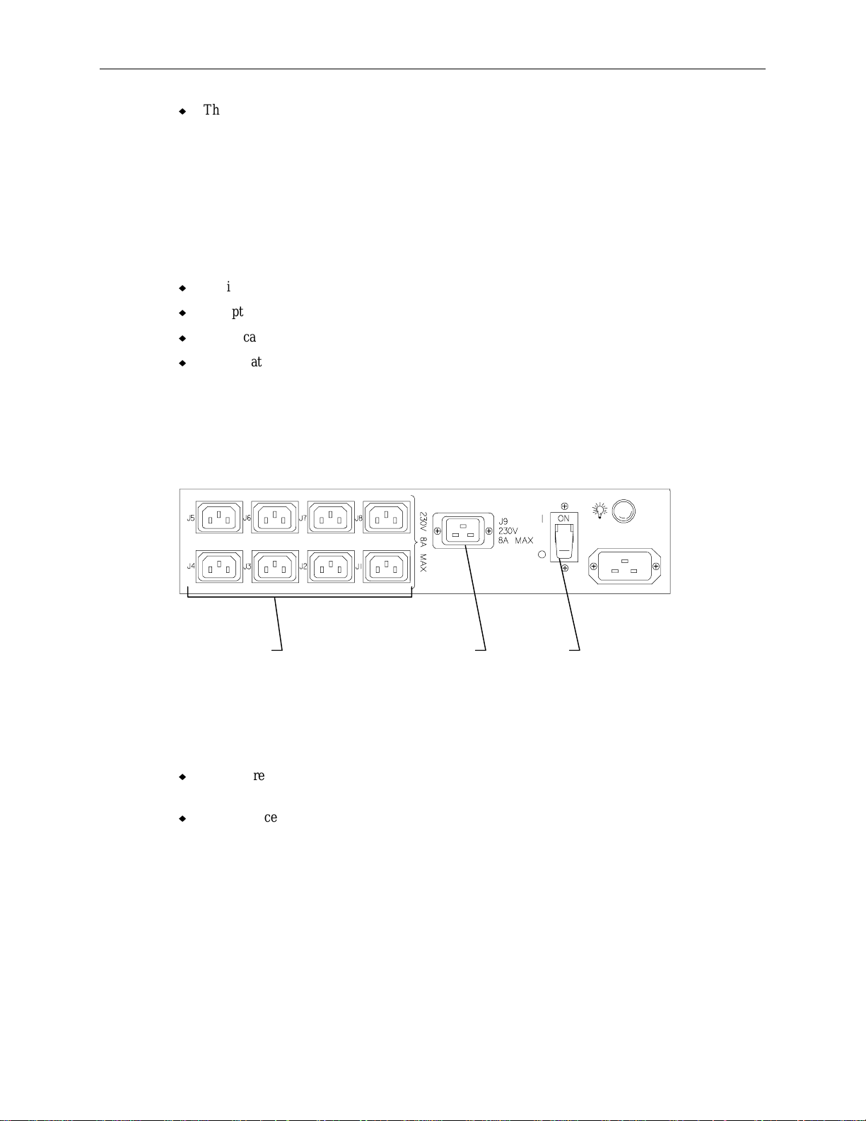
Non-Domestic AC Distribution Box
Specifications for the non-domestic AC distribution box include:
u
AC input: 190/264 VAC 50 Hz, 16 Amperes
u
Receptacles: eight IEC 320 10 Amperes, and one IEC 320 16 Amperes
u
Power cable: 2.5m with IEC 309 16 Amperes plug
u
Output rating: 3520 VA total @ 220 VAC
The non-domestic AC distribution box is rated for a maximum output rating of 3520 VA (Voltamperes) at 220 VAC. The sum-total VA load that the devices pull must not exceed this maximum,
else a breaker in the AC distribution box trips when power is applied. A second AC distribution box
must be installed to provide the additional power requirement. The following figure shows the nondomestic AC distribution box.
3
IEC 320 IEC 320 Power
10 Amp 16 Amp switch
Each receptacle on the AC distribution box is rated for a specific VA. The IEC 320 16 Ampere
receptacle (J9) is used for the power cord from the base unit. The remaining eight IEC 320 10 Ampere
receptacles are for additional devices installed in the rack. Follow these guidelines when connecting
equipment power cords:
u
If the J9 receptacle is not used, then the eight 10 Ampere receptacles (J1-J8) can support the full
3520 VA load.
u
If the J9 receptacle is used, then the eight 10 Ampere receptacles (J1-J8) can support only 1760
VA load.
WARNING The wall outlet to which the AC distribution box is connected must be an IEC 309 type outlet on
a properly grounded branch circuit.
Page 14

4
Equipment Power Loads
The power load values for the base unit and disk array cabinet are provided below. Load values of
equipment must be taken into account when installing equipment to the rack.
Device
System base unit with eight drives 1200 VA
Disk drive cabinet with eight 4 GB drives 265 VA
Disk drive cabinet with eight 9 GB drives 261 VA
4-port concentrator 8 VA
8-port concentrator 10 VA
PC Extender 13 VA
The VA load of Intergraph rack-mount options is printed on the back of the device. Add the VA load
for each device to determine if the AC distribution box can handle the load. If it cannot, add an
additional AC distribution box. The VA load of a device is the product of its operating Voltage (such
as 110 V or 220 V) times its current rating (2 Amperes, 3 Amperes, 6 Amperes, etc.).
Placing the System
Before you unpack the equipment and begin setting up your server, determine where you want to place
the system rack. Keep these guidelines in mind:
u
Place the rack as close as possible to the proper wall outlet. The power cord connecting the AC
distribution box or UPS to the wall outlet serves as the disconnect device.
u
Place the rack in an area where air can circulate freely around it. Ensure that the front and the back
of the rack each have 36 inches of clearance for servicing the installed hardware.
Max Load
u
Do not expose the system to high levels of dust, smoke, or moisture.
u
Place the system in an area where the temperature range stays between 10 °C and 26 °C (50 °F to
80 °F). The optimum operating temperature is 21 °C (70 °F).
u
Place the system in an area where the humidity stays between 20 and 80 % (non-condensing). The
optimum operating humidity is 50 % (non-condensing).
u
The rack is not designed to be moved when equipment is installed (other than what is pre-installed
by Intergraph).
WARNING Once you install the equipment, do not move the rack. If you must move it, then remove all
equipment, move the rack to its new location, and re-install the equipment.
Page 15
2 Installing the InterServe 650, 660
This chapter provides instructions for installing the InterServe equipment into the Intergraph rack. The
equipment is secured in the rack along the side mounting posts, which have industry standard
7.1 mm diameter mounting holes along the edge. The mounting posts have small round markers to
designate each vertical unit. There are three mounting holes per U, and at every 4 U there is a small
square marker. The total vertical mounting height within the rack is 40 U.
The system components should be installed in the following order:
u
Uninterriptible Power Supply (UPS)
u
InterRAID-8 disk array cabinet
u
InterServe base unit
u
Rackmount interface (keyboard, mouse, monitor)
u
RAID disk drives
u
System power and data cables
u
Rack cable handlers
5
u
Accessory components
WARNING Follow the installation instructions explicitly to avoid personal injury and damage to the server
hardware.
CAUTION To keep the rack from moving, ensure the front and side stabilizers are fully engaged and the leveling
feet are lowered firmly to the floor before installing equipment into the rack.
Note the following points before installing equipment into the rack:
u
The rack must be properly set up before placing any equipment into the rack. If installing the
equipment into an Intergraph rack, follow the instructions in Intergraph Rack Installation and Use
(DHA0194x) supplied with the rack.
u
Do not start the system until it has been completely set up. After setup is complete, refer to the
System Setup for startup and configuration instructions.
u
As equipment is installed into the rack, some components may not align properly with the holes in
the mounting posts. This occurs because some components have different tolerances in regards to
their height. If components do not align properly, loosen their screws and adjust support rails and
shelves where necessary so the components can be suppoerted by the proper shelves or rails, rather
than by the component underneath.
Page 16
6
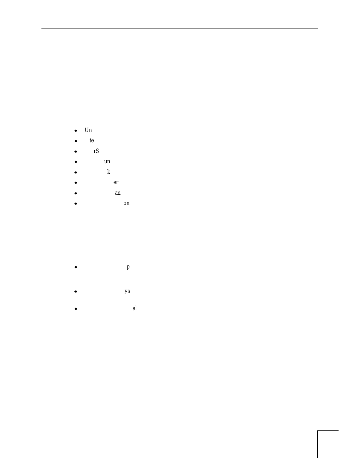
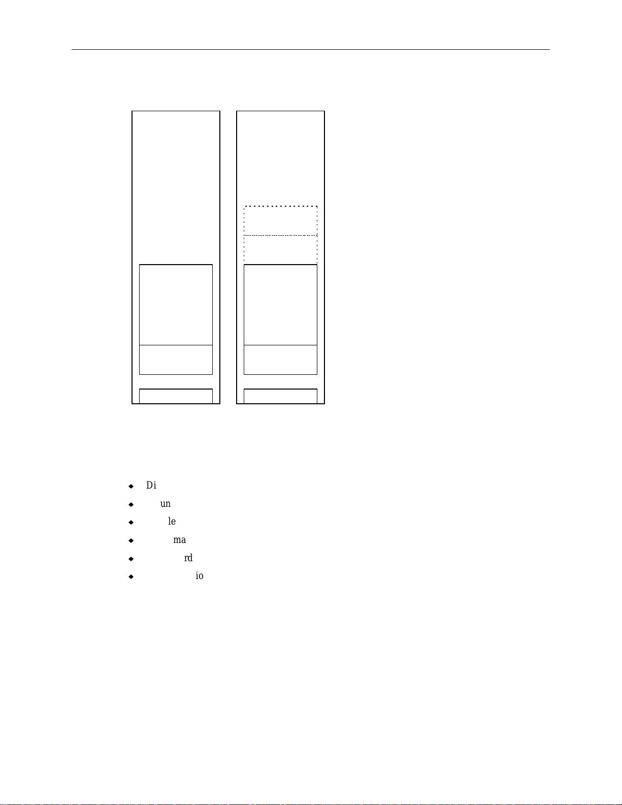
The following figure shows how various configurations look when fully installed, with UPS or AC
boxes. Optional InterRAID-8 cabinets (shown by dashed lines) also depict example placement. These
figures do not attempt to show every possible configuration.
Monitor
InterRAID-8
InterRAID-8
InterRAID-8
InterRAID-8
InterServe
InterRAID-8 InterRAID-8
AC Dist Box AC Dist Box
InterServe
UPS
UPS
InterRAID-8
InterRAID-8
InterServe
UPS
Monitor
Keyboard
Drawer
InterServe
InterRAID-8
Uninterruptible Power Supply
The UPS carton contains the UPS, serial cable, and documentation. The LanSafe III software used to
monitor and configure the UPS is also included with the system.
NOTE The door hinges for the rack must be installed before installing the UPS in the bottom of the rack. For
instructions, refer to
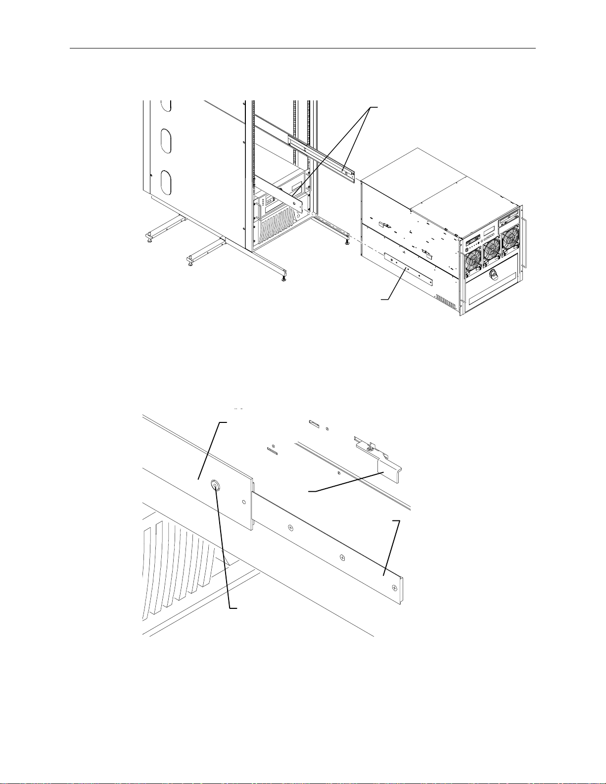
To install the UPS into the rack:
1. Insert tinnerman nuts at hole 3 and hole 10 in the front edge of the mounting post.
2. Slide the UPS through the front of the rack, and ensure the back of the UPS rests on the mounting
shelf inside the rack.
Intergraph Rack Installation and Use
.
Page 17
3. Attach the UPS to the rack using a screw at each corner.
Hole 11
7
Mounting Post
Front Edge of Post
UPS
Hole 2
4. Install the second UPS if included with the shipment. Install tinnerman nuts at hole 15 and hole 22
for the second UPS.
InterRAID-8 Cabinets
Unpack the InterRAID-8 from the carton and verify you have the following items.
u
Disk array cabinet
u
Mounting hardware
u
Handle brackets and screws
u
Tinnerman nuts and screws
u
Power cord
u
Documentation
The mounting hardware includes two shelves to be mounted inside the rack, and two brackets to be
attached to the InterRAID-8 cabinet.
Page 18
8
To install the InterRAID-8 cabinet into the rack:
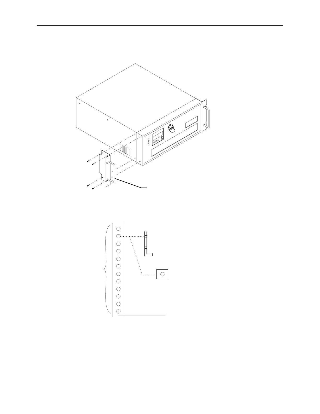
1. Attach the handle brackets to both sides of the InterRAID-8 cabinet. Use the eight panhead screws
(four for each bracket) supplied with the InterRAID-8.
Handle Bracket
NOTE The sides of the InterRAID-8 have different hole patterns to match the pattern in each handle bracket.
2. Determine the 4 U space in which to install the InterRAID-8. The following figure shows where
the mounting shelf and tinnerman nut must be installed in a given 4 U space.
Mounting Shelf
(End View)
(12 Holes)
Tinnerman
Nut
Bottom edge of
InterRAID-8 here
Page 19
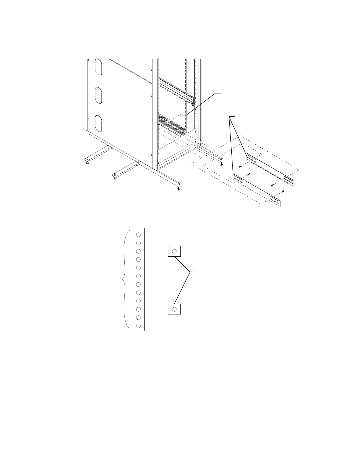
2. Attach the mounting shelves to the rack. Place tinnerman nuts for the shelves on the interior face
of all four mounting posts. Refer to the following figure.
Interior Face of
Mounting Post
Mounting Shelves
9
4. Place tinnerman nuts for the InterRAID-8 faceplate on the exterior face of both front mounting
posts. The following figure shows the tinnerman nut locations for the 4 U space.
4 U (12 Holes)
Tinnerman Nuts
Page 20
10
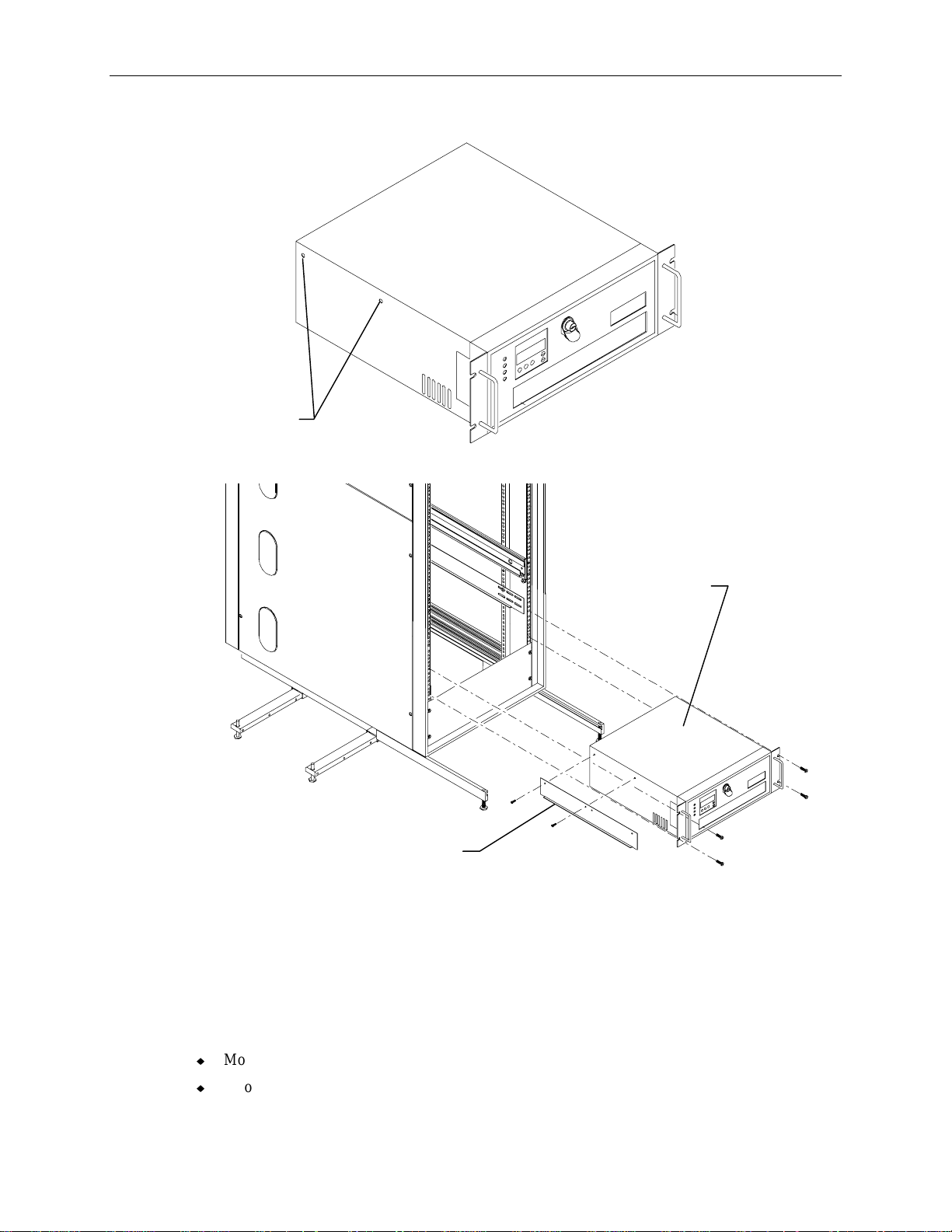
5. Remove and discard the flat head screws from both sides of the InterRAID-8 cabinet as shown.
Flat Head
Screws
6. Attach the mounting brackets to the InterRAID-8 and slide it into the rack as shown.
Mounting Bracket
(Note ledge is turned away
from InterRAID-8 cabinet.)
7. Secure the disk array cabinet to the rack using the screws supplied with the InterRAID-8.
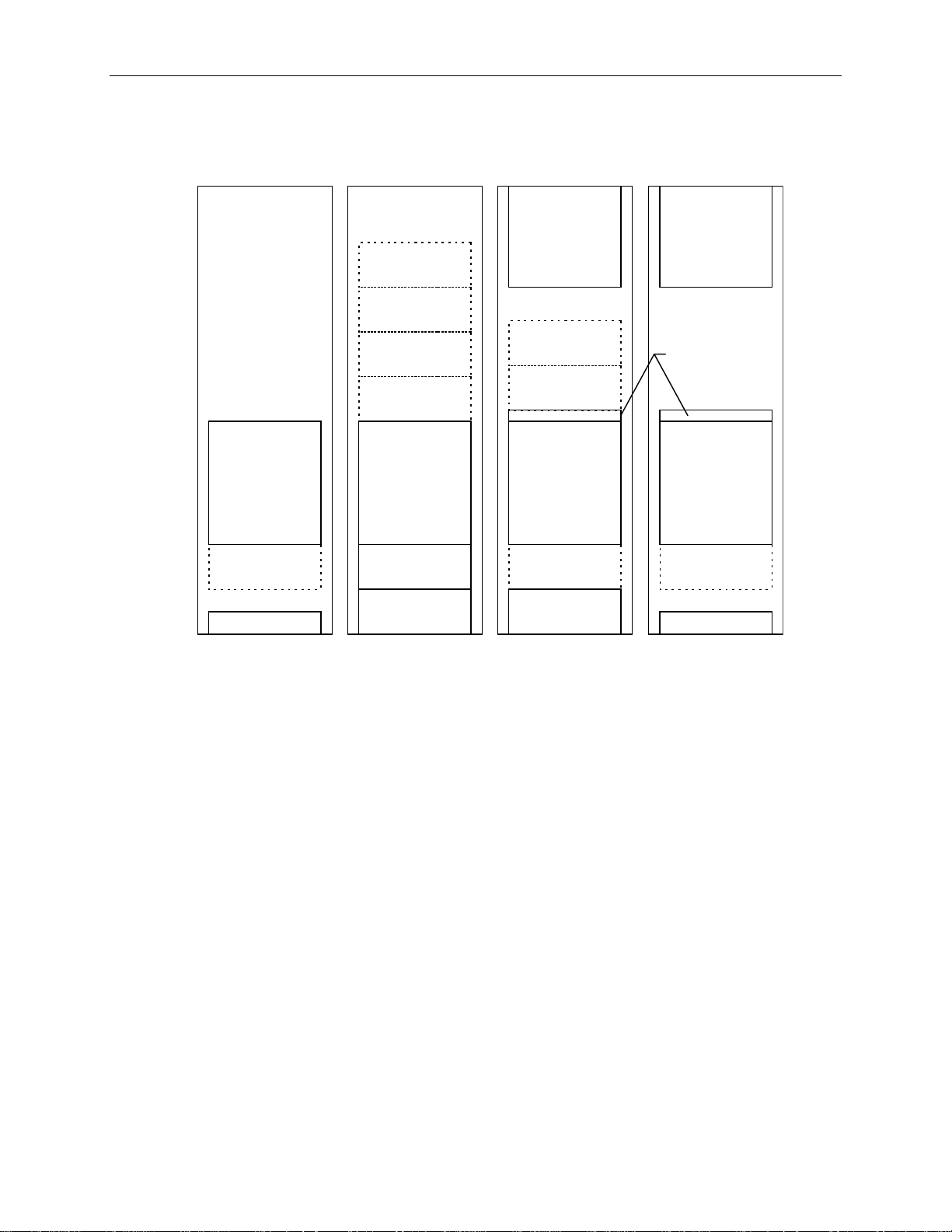
InterServe Base Unit
Two boxes are included with the base unit: one for the keyboard, and one for software media and
miscellaneous parts. The software media and miscellaneous parts box contains the following items:
InterRAID-8
Cabinet
u
Mouse
u
Two cable handlers
Page 21
11
u
Screws and tinnerman nuts
u
Keys for base unit and internal RAID section
u
Power cord
u
Windows NT Server kit (software and documentation)
u
Intergraph system software (diskettes)
u
Intergraph InterServe 650, 660 System Introduction (diskette)
WARNING The server base unit is very heavy and bulky. Two people must lift the base unit when removing
it from the pallet and installing it into the rack.
To install the server into the rack:
1. Place the pallet close to the rack.
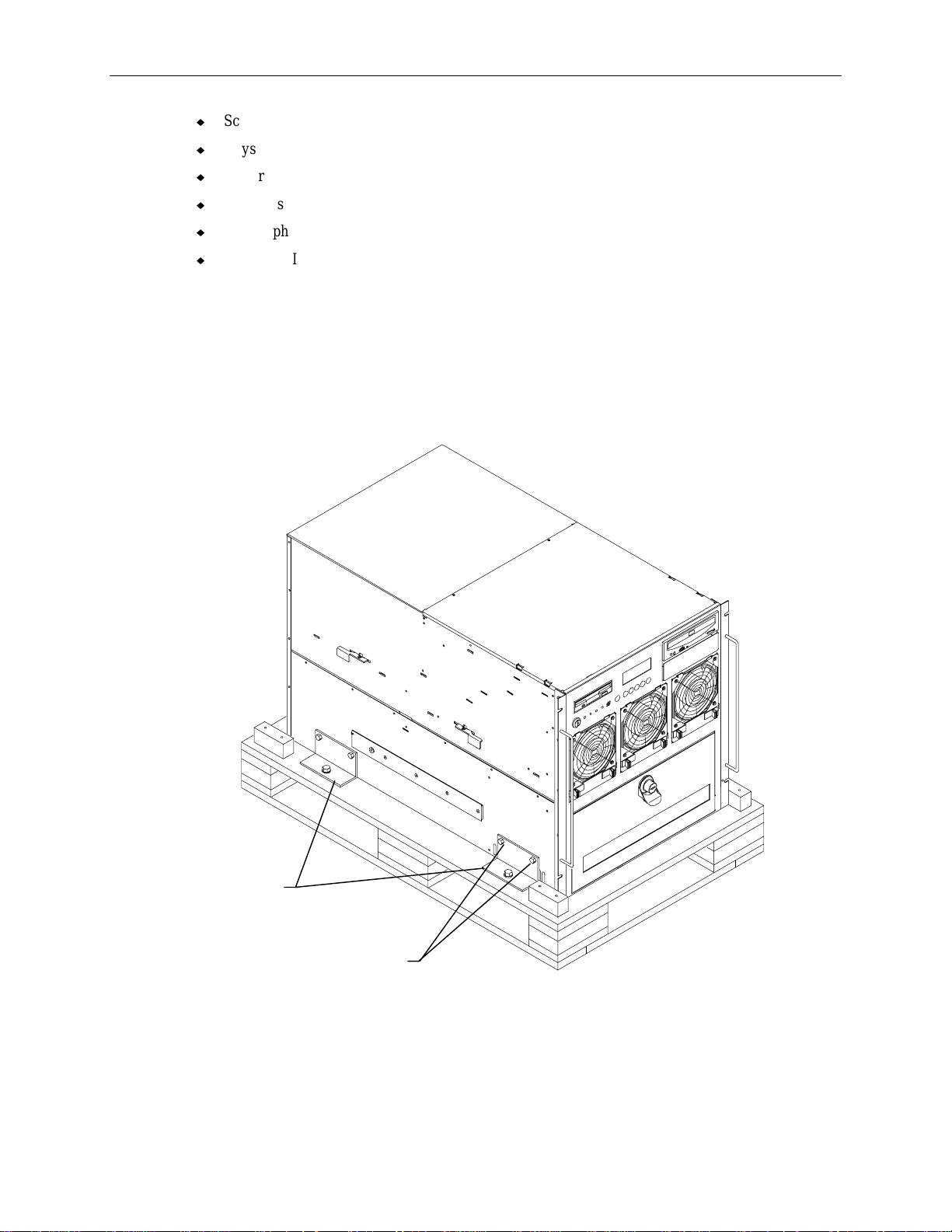
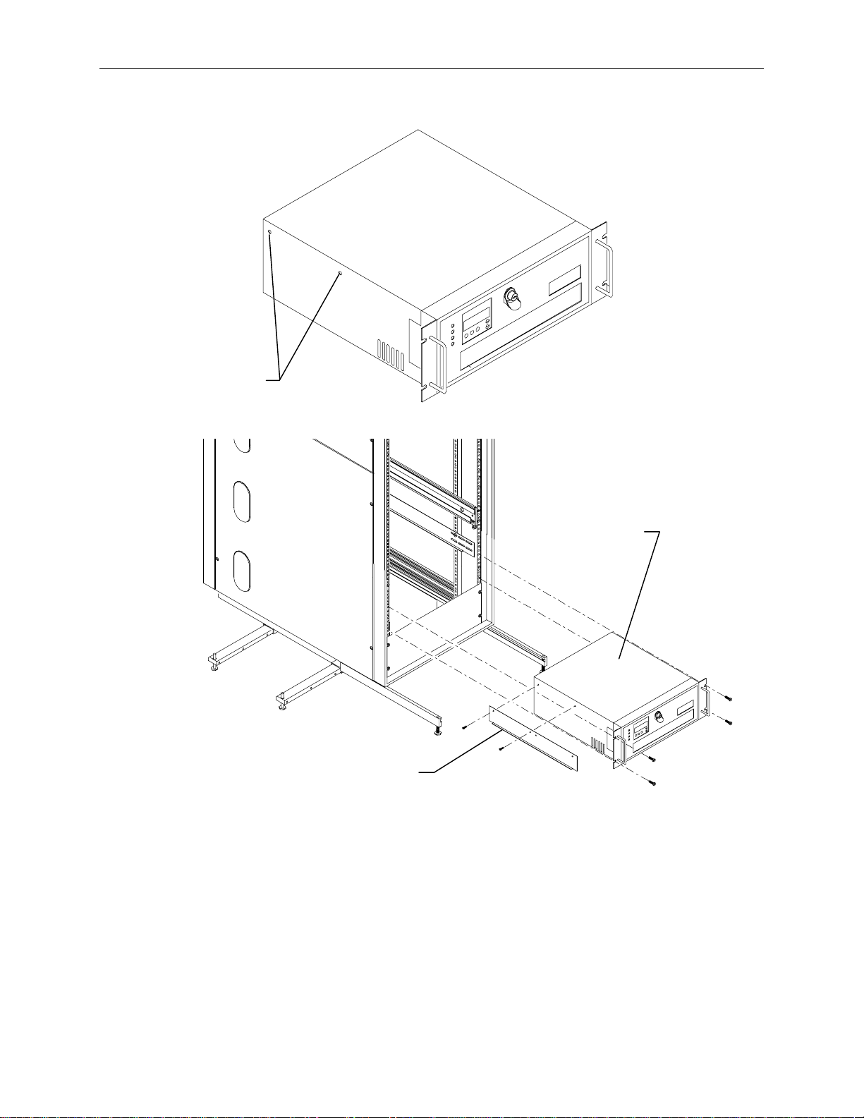
2. Four brackets secure the base unit to the pallet. Remove the two upper screws from each bracket
as shown in the following figure.
Brackets
Screws
3. Insert tinnerman nuts in holes 27 and 55 on both front mounting posts of the rack.
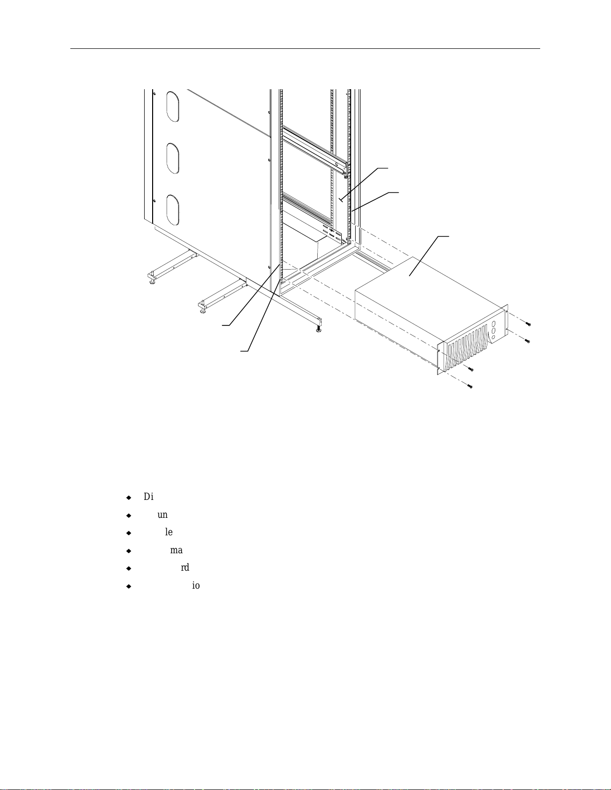
4. Extend the base unit rails from the rack until they lock. Refer to the following figure.
Page 22
12
5. With a person on either side, lift the base unit and align the base unit rails in the rack with the rail
guides mounted on the side of the base unit.
Base Unit
Rails
Rail Guide
(Each Side)
6. Slide the base unit into the rails and push the base until it stops. The metal rail button in the rail
guides hits against the base unit rail. Press the rail buttons on both sides and continue pushing the
base unit. The base unit will stop again and the metal rail button appears in the hole of the base
unit rails. Refer to the following figure.
CAUTION Ensure the board ejectors on both sides of the base unit are closed. They will interfere with the
mounting rails if not fully closed.
Base Unit
Rail
Board
Ejector
Rail
Guide
Rail
Button
7. Press the rail buttons on both sides and push the base unit into the rack.
Page 23
Rack-mount Interface Kit
This section describes installing the rack-mount keyboard, mouse and monitor into the rack. The box
for the rack-mount monitor contains the monitor, video cable, monitor AC power cord, and
documentation.
NOTE Mounting hardware (adapter bracket, bracket insert, star washers, and screws) for the monitor is
included with the rack.
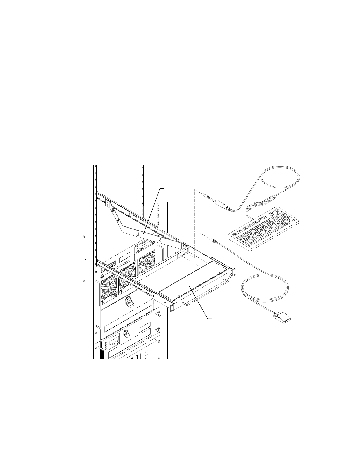
To install the keyboard and mouse into the rack:
1. Pull out the tray until it locks in the extended position.
2. Route the keyboard and mouse cables through the opening in the back of the tray and through the
four clamps in the cable guide.
3. Set the keyboard into the tray.
4. Open the hand-rest tray and set the mouse into it.
Cable
Guide
13
Hand Rest
Tray
Page 24
14
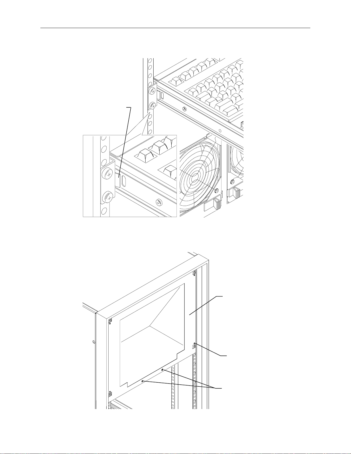
5. To retract the keyboard and mouse tray, press the rail tabs on both sides of the tray, then push the
tray into the rack.
Push in to retract
keyboard tray.
To install the monitor into the rack:
1. Remove the monitor cover plate from the rack. Screws are located at each corner and along the
bottom of the plate.
Monitor
Cover
Plate
Screw
Screws
Page 25
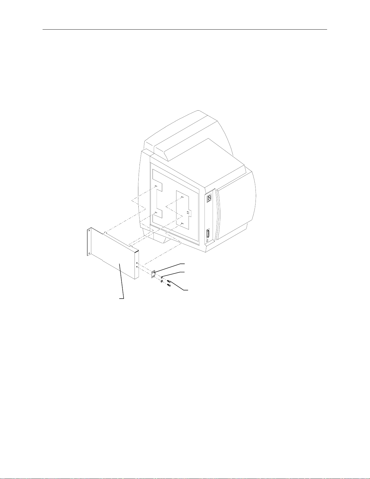
2. Turn the monitor on its side and remove the base from the monitor. Do not turn the monitor onto
its display screen.
3. Attach the screws, star washers, and bracket insert to the adapter bracket as shown in the following
figure.
NOTE There are two bracket inserts to accomodate two versions of the 15-inch monitor. CFAB546 for the
Sampo 510, and CFAB622 for the Sampo 520.
4. Attach the adapter bracket to the bottom of the monitor.
15
Adapter
Bracket
5. Set the monitor onto the shelf though the front of the rack.
6. Secure the monitor with two screws through the front of the adapter bracket.
7. Attach the monitor cover plate onto the rack.
Remote Interface Kit
A keyboard, mouse, and monitor concentrator is included with the remote interface kit. The
concentrator comes with a 25-foot-long cable set that connects between the base unit and the
concentrator.
To install the remote interface kit:
1. Place the keyboard, mouse, and monitor in the desired location, up to 25 feet away from the base
unit.
2. Connect the keyboard, mouse, and monitor cables to the concentrator.
Bracket Insert
Star Washers
Screws
Page 26
16
3. Connect the cable set to the base unit and to the concentrator. Refer to the concentrator
documentation for details.
RAID Disk Drives
The box labeled “This box contains hard disks loaded with operating system software” contains up to
six disk drives. Three of them are boot drives, each labeled with a drive ID number (0, 1, 2). The boot
drives are loaded with the operating system and must be installed into the internal RAID section of the
server base unit. If additional disk drives are included in the box, they are unformatted and not labeled.
The box also contains a drive labeling sheet to be used with the unformatted disk drives. If you
received additional disk drive boxes, the disk drives will be unformatted, and should be installed into
the rack-mount InterRAID-8 cabinets.
To install the RAID disk drives:
1. Remove the disk drives from the box.
2. Open the disk drive door to the internal RAID section.
NOTE Use the key supplied in the base unit parts box to open the disk drive door. Insert the key and turn it
clockwise to unlock, counterclockwise to lock.
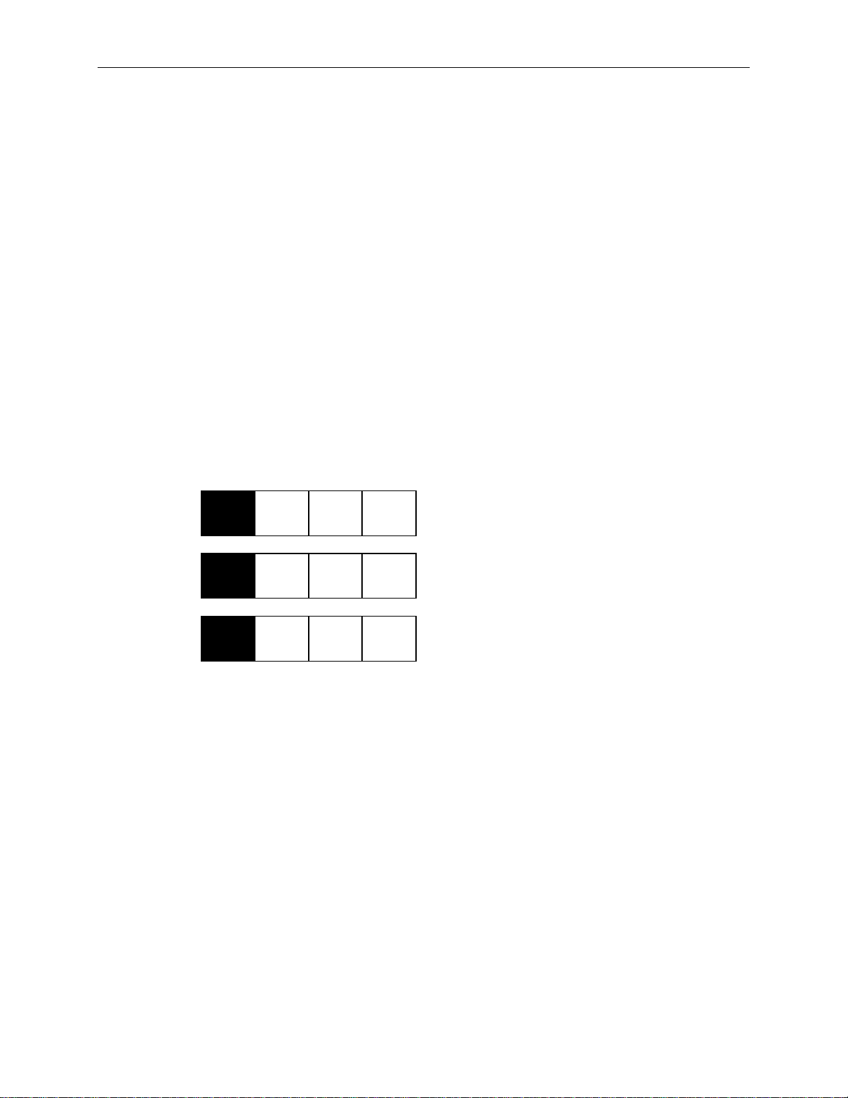
3. Remove the RAID disk drives from the drive box. Each boot drive is labeled with an adapter
number (ADP), channel number (CHN), and drive ID, as shown:
x GB
x GB
x GB
ADP
0
ADP
0
ADP
0
CHN
2
CHN
2
CHN
2
ID
0
ID
1
ID
2
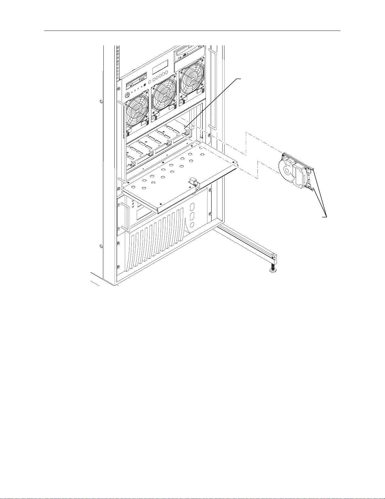
4. Install the boot drives into the system’s internal RAID slots as follows: drive ID 0 into slot 1, drive
ID 1 into slot 2, and drive ID 2 into slot 3. Slots are numbered 1 to 8 starting with the right slot.
Refer to the following figure.
−
For each RAID disk drive, extend the latching clips on the disk drive and align the rails on the
side of the drive with the slot guides. The metal casing of the drive faces left. If you install
the disk drive reversed, the drives will not connect to the system.
−
Push the drive between the latching clips until it slides all the way into the slot and firmly
engages the connector.
− Close the latching clips to lock the drive in the slot.
Page 27
Slot 1
17
Drive Latching
Clips
6. Install the remaining disk drives from right to left after the boot drives are installed. Fill each slot
sequentially. There should be no empty slots between drives.
Page 28
18
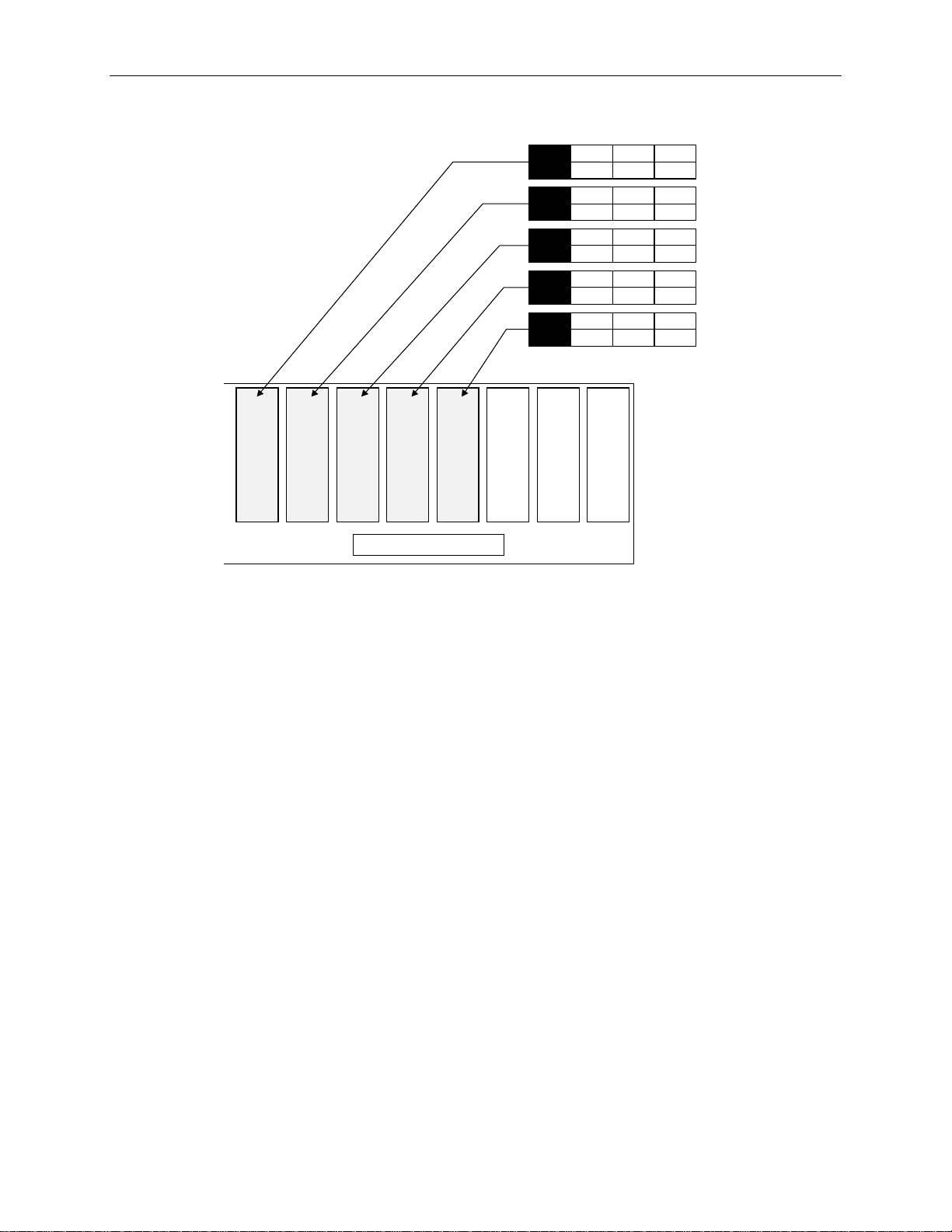
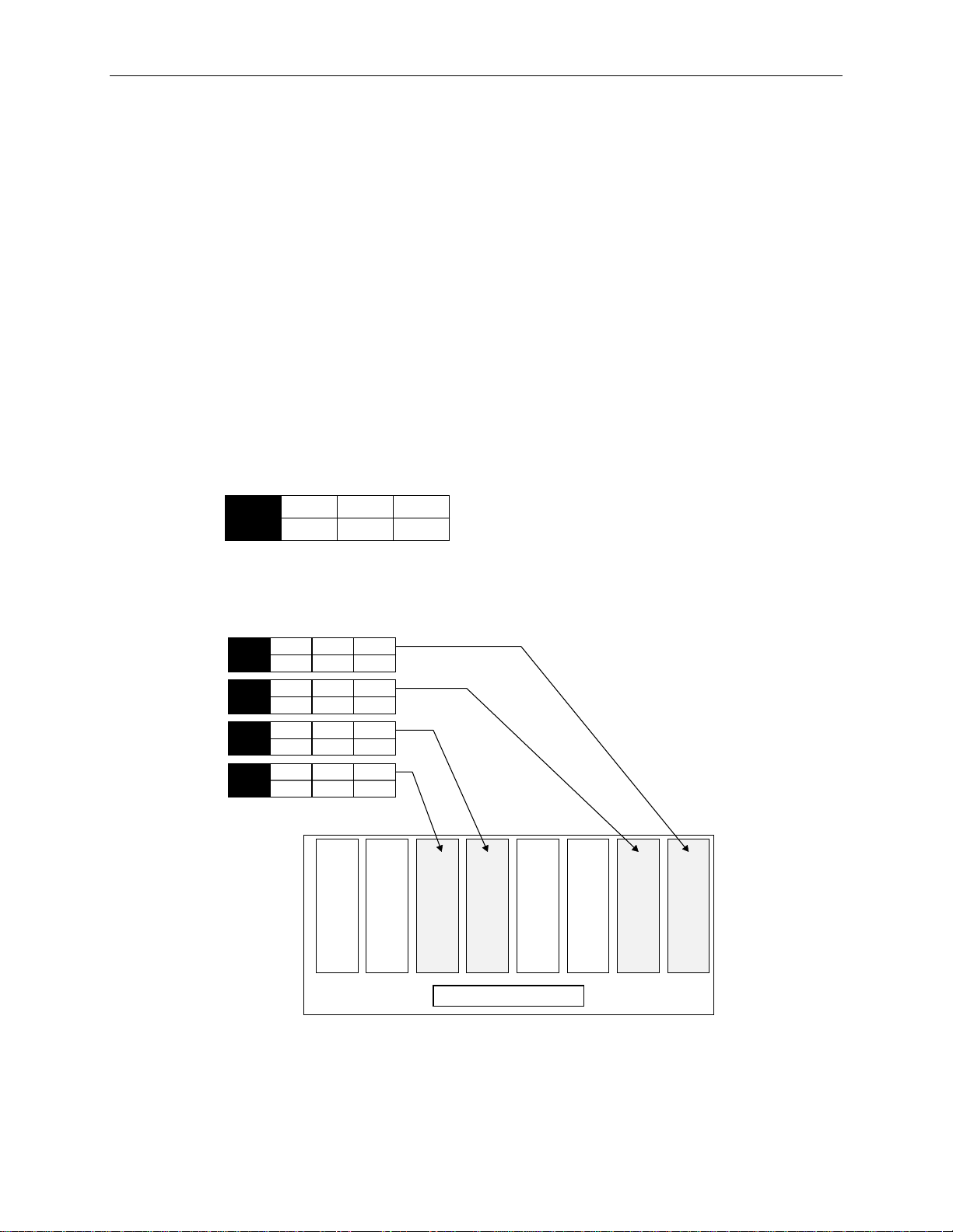
7. Label the remaining drives according to their slot, as shown in the following figure.
9
2
x GB
x GB
x GB
x GB
x GB
Slot 2 Slot 1Slot 3Slot 4Slot 5Slot 6Slot 7Slot 8
0
ADP
0
ADP
0
ADP
0
ADP
0
ADP
CHN
2
CHN
1
CHN
2
CHN
2
CHN
ID
8
ID
6
ID
5
ID
4
ID
Internal Disk Cabinet
NOTE ID 3 and ID 7 are not available on the label sheet. These IDs are reserved for the internal RAID
backplane and the RAID controller.
5. If your system includes external InterRAID disk array cabinets, refer to the InterRAID
documentation for instructions to connect them to your system.
WARNING Do not turn on system power until you are ready to configure Windows NT Server. If you start
the system, and then restart it before completely configuring the operating system, you will have
to re-install system software as described in Chapter 5, “Installing System Software.”
System Cables
All cable ports on the base unit and other Intergraph equipment are keyed or molded to ensure proper
cable attachment. If a cable is not attaching easily, ensure that you are aligning the cable connector
correctly with the port.
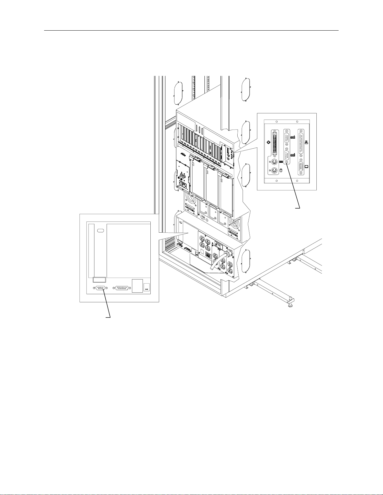
Keyboard, Mouse and Monitor
To connect keyboard, mouse and monitor cables:
1. If using the concentrator, connect the extension cables to the keyboard, mouse, and video ports.
Page 29
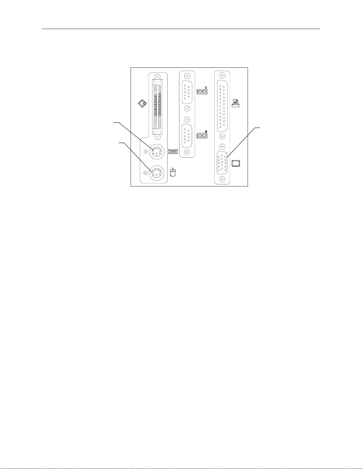
2. If using the rack-mount kit, connect the keyboard and mouse cables to the ports on the back of the
base unit. Connect the video cable to the video port and to the monitor. Refer to the following
figure.
19
Keyboard
Port
Mouse Port
Video Port
3. Connect the monitor power cord to the monitor and to the AC distribution box, UPS, or wall
outlet.
4. Connect the concentrator power cord to the AC distribution box, UPS, or wall outlet.
Page 30
20
RAID Controll
InterRAID-8
To connect InterRAID-8 cables:
1. Connect the RAID SCSI cable to the InterRAID-8 SCSI port and to a RAID controller SCSI port
in the base unit. Refer to the following figure.
NOTE On the RAID controller, the top port is channel 0, and the bottom port is channel 1. Keep track of the
InterRAID-8 attached to each channel, for drive labeling purposes.
SCSI Ports
(PCI Slot 4)
er
InterRAID-8
SCSI Port
2. Connect the power cord to the InterRAID-8 cabinet and to the AC distribution box or UPS.
Page 31

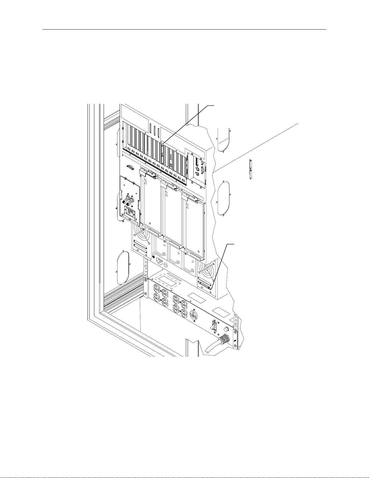
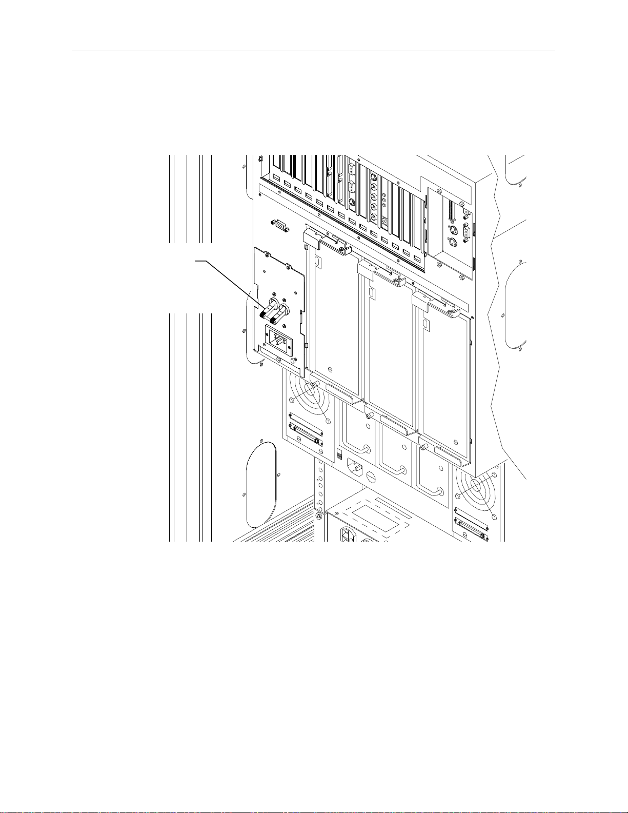
Intruder Alert
The server base unit contains the circuitry for the intruder alert, which must be connected to the alert
switches in the top of the rack. If installing two Intergraph racks, where one contains only option
equipment (disk array cabinets, networking devices, etc.) then the expansion rack can be connected to
an adjacent rack containing the base unit. When unauthorized entry is made into the expansion rack,
the intruder alert in the base unit will activate. Chapter 3, “Using the System” of the System Setup
describes how to activate and de-activate the intruder alert.
To connect the intruder alert cable for an individual rack:
1. Connect the intruder alert cable to the intruder alert port. Intergraph installs the intruder alert
21
cable into the back of the rack before shipment.
Intruder Alert Cable
2. Ensure the other end of the intruder alert cable, and the white loop-back connector are attached to
the sockets in the top corner of the rack. Refer to the following figure.
Page 32

22
Intruder Alert
Cable
Loopback
Connector
To connect the intruder alert cable for adjacent racks:
1. For the system rack containing the base unit, connect the intruder alert cable as for an individual
rack.
2. Remove the loopback connector from the system rack, as shown in the following diagrams.
3. Remove the top access panel in each rack.
4. Connect the link cable to the socket in the base unit rack and to the empty socket in the options
rack, as shown in the following diagrams. The link cable must run through the access panel
openings in each rack.
Page 33

System Rack on the Right:
Move loopback connector
23
Attach cable to
open socket
Expansion Rack
System Rack on the Left:
Remove
this jumper
Link
Cable
Front of Racks
Link
Cable
Remove
loopback
connector
Base Unit
System Rack
to open socket
Base Unit
Syst em Rack
Expansion Rack
Front of Rac ks
Page 34

24
Expansion Board Cables
The InterServe base unit includes the following expansion boards as standard equipment:
Standard Board
Slot
RAID Controller (CINF917) PCI 4
100 Base-T Fast Ethernet Network Adapter (CINF920) PCI 2
InterSite Server Monitor (FINF029) ISA 4
The following figure shows the slots on the back of the base unit. Connect the cables to the Ethernet
and InterSite Server Monitor card as described in the documentation for those cards.
RAID
Controller
12 11 10 9 8 7 6 5 4 3 2 1 1 2 3 4
Ethernet
Card
InterSite Server
Monitor Card
PCI Slot s
ISA Slots
If additional expansion boards are installed in the system, refer to the option board documentation for
cable hookup procedures.
Page 35
UPS Serial Cable
Connect the serial cable to the UPS and to the base unit as shown in the following figure.
25
Serial
Port
Serial
Ports
Page 36

26
System Power Cord
To connect the system power cord:
1. Ensure the base unit circuit breaker switch is in the Off (down) position before attaching the power
cord to the system and wall outlet.
2. Connect the system power cord to the base unit AC receptacle and to the proper receptacle of the
AC distribution box or UPS.
Circuit Breaker
Switch (Off
position)
Power
Cord
3. Connect the power cord to the AC distribution box or UPS and to the wall outlet (NEMA
L14-20R or IEC 309).
NOTE The UPS starts automatically when its power cord is connected to the wall outlet. Refer to the UPS
documentation for more details.
WARNING The wall outlet must be on a properly grounded branch circuit.
Page 37
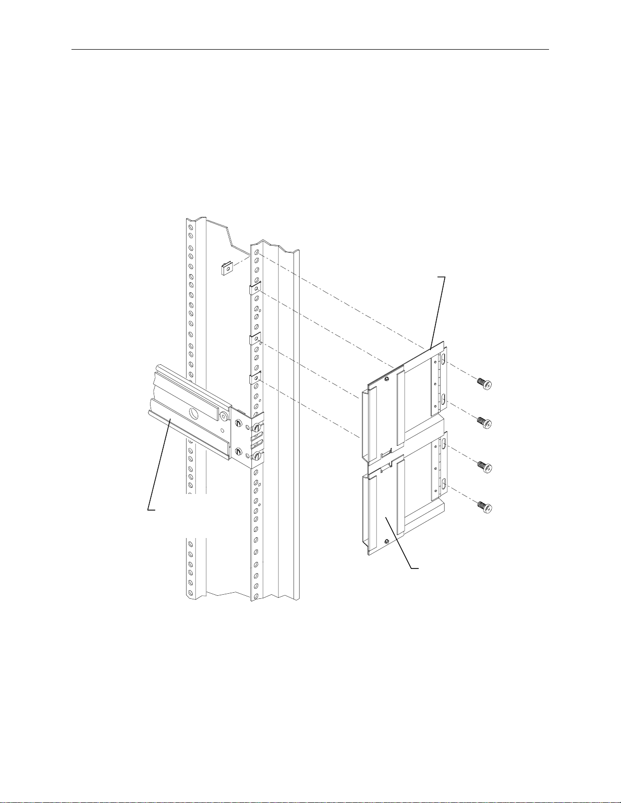
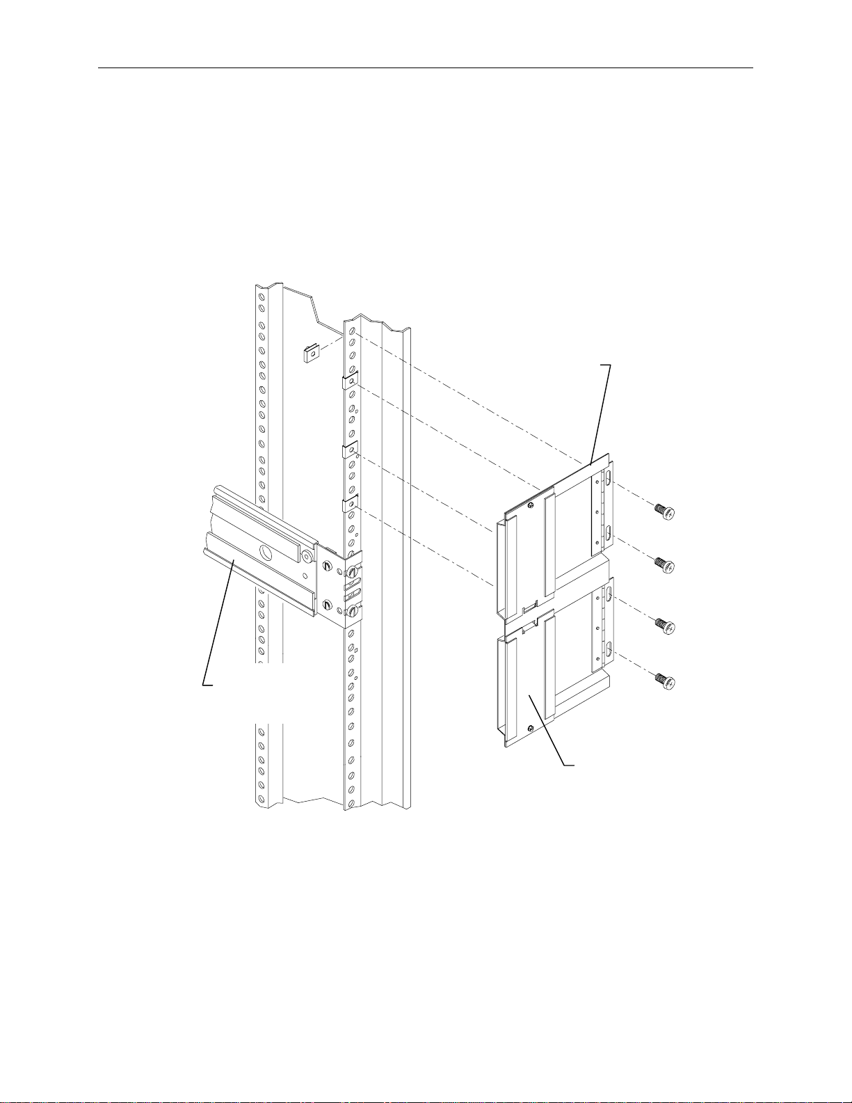
Cable Handlers
To install cable handlers:
1. Extend the base unit to provide room in the back of the rack for installing the cable handlers.
2. On a rear mounting post, count 5 holes above the top of the base unit rail and attach a tinnerman
nut. Count an additional 4, 5, and 4 holes and attach tinnerman nuts. Repeat this for the other rear
post. Refer to the following figure.
3. Attach the cable handler to the rail using four screws. The part of the cable handler that comes off
(for inserting cables) must face the rack walls. Refer to the following figure.
27
Cable
Handler
Base Unit
Rail
This side faces
rack wall
NOTE Most cables that attach to the system base unit must be inserted into one of the cable handlers. The
cable handlers allow the base unit to be extended without risk of damaging cables or pulling them out
of other devices. The following figure shows how the cables are inserted.
Page 38

28
These ends to the
devices
These ends to the
base unit
To route cables:
NOTE The base unit must be extended to insert cables into the cable handler.
1. Connect all the system power cords and data cables to the base unit and to the AC distribution box
or UPS.
2. Insert all cables that attach to the base unit (except for keyboard and mouse cables) into the cable
handler.
3. Additionally, there are cable ties and clamps along the rear mounting rails of the rack. Route
cables through these ties and clamps if necessary.
NOTE Cables that are attached to the base unit and connect to devices in another rack must also be inserted
into the cable handler.
4. After routing the cables into the cable handlers, fully extend the base unit to ensure there is enough
service loop in the cables.
Page 39

Additional Rack-mount Equipment
Network hubs, routers, serial devices and other types of equipment may be installed into the rack,
provided the power requirements are within the available limits of the installed AC distribution box or
UPS.
CAUTION Refer to “Safety Precautions” and “Power Requirements” in Chapter 1, before attempting to install
additional equipment.
WARNING If using non-Intergraph cables with the system, ensure that they are shielded and terminated on
both ends.
To install additional equipment into the rack:
1. Ensure that the installed AC distribution box or UPS can support the additional equipment.
2. Install the necessary mounting shelves or rails to support the equipment into available space. Use
tinnerman nuts for the shelves or rails.
3. Install the equipment, and place tinnerman nuts where the equipment will bolt into the rack.
Secure the equipment to the rack.
4. Connect the cables to the equipment and to the appropriate ports on the back of the base unit.
29
All cable ports on the base unit and other Intergraph equipment are keyed or molded to ensure proper
cable attachment. If a cable is not attaching easily, ensure that you are aligning the cable connector
correctly with the port.
Checking the Setup
Before starting the system, review the following items:
u
All hardware is properly and securely installed, and all RAID disk drives are installed in the
correct locations.
u
The cables are properly attached from the base unit to the various options and peripherals installed
in the rack or in remote locations.
u
The cables attached to the server base unit are routed through the cable handler. Ensure there is
enough cable service loop to allow sliding devices to extend 31 inches.
u
The cables that run along the sides or top of the rack are installed in clips or ties to secure them in
place.
u
The power cord from the AC distribution box or UPS is attached to the correct wall outlet.
u
The base unit is retracted and secured to the rack with screws at each corner.
Starting the System
Go to the System Setup, delivered with the system, to start the system for the first time and configure
the operating system and system software.
Page 40

30
Page 41

3 Installing the StudioZ RAX
This chapter provides instructions for StudioZ RAX equipment into the Intergraph rack. The
equipment is secured in the Intergraph rack along the side mounting posts, which have industry
standard 7.1 mm diameter mounting holes along the edge. The mounting posts have small round
markers to designate each vertical unit. There are three mounting holes per U, and at every 4 U there is
a small square marker. The total vertical mounting height within the rack is 40 U.
WARNING Follow the installation instructions explicitly to avoid personal injury and damage to the server
hardware.
CAUTION To keep the rack from moving, ensure the front and side stabilizers are fully engaged and the feet are
lowered to the floor before installing equipment into the rack.
31
NOTE Do not start the system until it has been completely set up. After setup is complete, refer to the
Setup
for startup and configuration instructions.
The system components should be installed in the following order:
u
InterRAID-8 disk array cabinet
u
StudioZ RAX base unit
u
RAID disk drives
u
System power and data cables
u
Rack cable handlers
u
Accessory components
Note the following points before installing equipment into the rack:
u
The rack must be properly set up before placing any equipment into the rack. If installing the
equipment into an Intergraph rack, follow the instructions in Intergraph Rack Installation and Use
(DHA0194x) supplied with the rack.
u
Do not start the system until it has been completely set up. After setup is complete, refer to the
System Setup for startup and configuration instructions.
u
As equipment is installed into the rack, some components may not align properly with the holes in
the mounting posts. If this occurs, known as tolerance buildup, you should loosen screws and
adjust support rails and shelves where necessary so the weight of the component is supported by
the mounting posts, rather than the component underneath.
System
Page 42
32
The following figure shows how the system should look fully installed. Optional InterRAID-8 cabinets
are shown by dashed lines.
InterRAID-8
InterRAID-8
StudioZ RAX
InterRAID-8
AC Dist Box
StudioZ RAX
InterRAID-8
AC Dist Box
InterRAID-8 Cabinet
Unpack the InterRAID-8 from the carton and verify you have the following items.
u
Disk array cabinet
u
Mounting hardware
u
Handle brackets and screws
u
Tinnerman nuts and screws
u
Power cord
u
Documentation
The mounting hardware includes two rails to be mounted inside the rack, and two brackets to be
attached to the InterRAID-8 cabinet.
Page 43

33
To install the InterRAID-8 disk array cabinet into the rack:
1. Attach the handle brackets to both sides of the InterRAID-8 cabinet. Use the eight panhead screws
(four for each bracket) supplied with the InterRAID-8.
Handle Bracket
NOTE The sides of the InterRAID-8 have different hole patterns to match the pattern in each handle bracket.
2. Determine the 4 U space in which to install the InterRAID-8 (normally in the lower section of the
rack as shown in the figure after step 3). The following figure shows where the mounting shelf and
tinnerman nut must be installed in a given 4 U space.
Mounting Shelf
(End View)
4 U (12 Holes)
Tinnerman
Nut
Bottom edge of
InterRAID-8 here
Page 44

34
3. Attach the mounting shelves to the rack. Place tinnerman nuts for the shelves on the interior face
of all four mounting posts. Refer to the following figure.
Interior Face of
Mounting Post
Mounting Shelves
4. Place tinnerman nuts for the InterRAID-8 faceplate on the exterior face of both front mounting
posts.
4 U (12 Holes)
Tinnerman Nuts
Page 45
5. Remove and discard the flat head screws from both sides of the InterRAID-8 cabinet as shown.
Flat Head
Screws
6. Attach the mounting brackets to the InterRAID-8 and slide it into the rack as shown.
35
InterRAID-8
Cabinet
Mounting Bracket
(Note ledge is turned away
from InterRAID-8 cabinet.)
7. Secure the disk array cabinet to the rack using the screws supplied with the InterRAID-8.
8.
Page 46

36
StudioZ RAX Base Unit
Two boxes are included with the base unit: one for the keyboard, and one for software media and
miscellaneous parts. The software media and miscellaneous parts box contains the following items:
u
Mouse
u
Two cable handlers
u
Screws and tinnerman nuts
u
Keys for internal RAID section and base unit
u
Power cord
u
Loopback VGA cable
u
Windows NT operating system kit (software and documentation)
u
Windows NT Service Pack 4 (CD-ROM)
u
Intergraph system software required to configure or re-install the operating system (diskettes)
u
Intergraph StudioZ RAX System Introduction (diskette)
NOTE The operating system is pre-installed on the fixed disk drive underneath the CD-ROM drive.
WARNING The base unit is very heavy and bulky. Two people must lift the base unit when removing it from
the pallet and installing it into the rack.
To install the base unit into the rack:
1. Place the pallet close to the rack.
Page 47
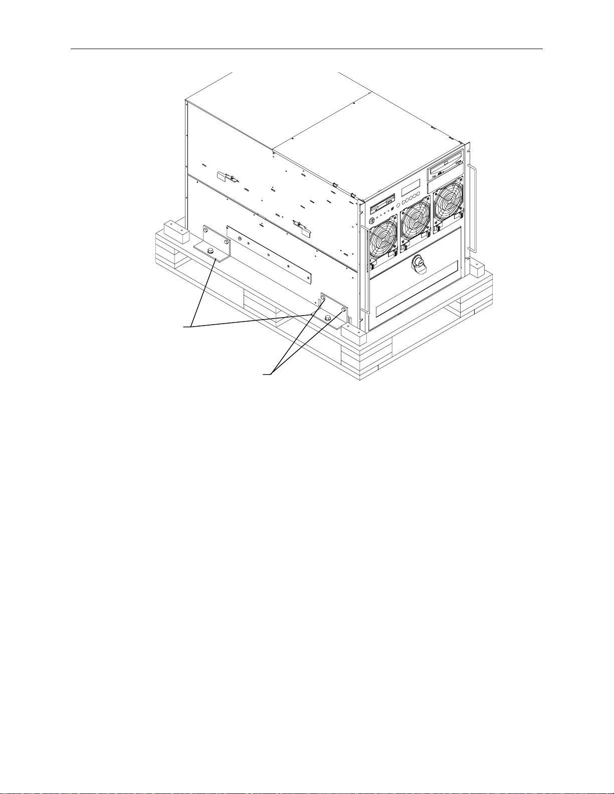
Brackets
37
Screws
2. Four brackets secure the base unit to the pallet. Remove the two upper screws from each bracket
as shown in the previous figure.
3. Insert tinnerman nuts in holes 27 and 55 on both front mounting rails.
4. Extend the base unit rails in the rack until they lock. Refer to the following figure.
Page 48

38
Base Unit
5. With a person on either side, lift the base unit and align the base unit rails in the rack with the rail
guides mounted on the side of the base unit.
Rails
Rail Guide
(Each Side)
7. Slide the base unit into the rails and push the base until it stops. The metal rail button in the rail
guides hits against the base unit rail. Press the rail buttons on both sides and continue pushing the
base unit. The base unit will stop again and the metal rail button appears in the hole of the base
unit rails. Refer to the following figure.
CAUTION Ensure the board ejectors on both sides of the base unit are closed. They will interfere with the
mounting rails if not fully closed.
Base Unit
Rail
Board
Ejector
Rail
Button
6. Press the rail buttons on both sides and push the base unit into the rack.
Page 49
RAID Disk Drives
The StudioZ RAX comes standard with eight RAID disk drives: four to be installed into the internal
disk drive section of the base unit, and four in the external InterRAID-8 cabinet. Two disk drive boxes
(one labeled “Internal” and one “External”) contain the disk drives and a drive labeling sheet. The
standard disk drives are pre-labeled with capacity (GB), adapter number (ADP), channel (CH), and slot
ID (ID).
If additional disk drives are shipped, they are included in separate boxes. These drives are unformatted
and have a blank label that must be completed after installing them. Before installing drives with a
blank label, install the drives in the “Internal” and “External” boxes first.
To install the standard RAID disk drives:
1. Open the disk drive door to the internal RAID section.
NOTE Use the key supplied in the base unit parts box to open the disk drive door. Insert the key and turn it
clockwise to unlock, counterclockwise to lock.
1. Remove the disk drives from the “Internal Drives” box. These drives contain a label similar to the
following:
39
x GB
0
ADP
1
CHN
0
ID
2. Open the access door of the internal disk drive section in the StudioZ RAX base unit. Slots are
numbered 1 to 8 from the right slot to the left.
3. Install the drives into slots 1, 2, 5, and 6, as shown in the following figure.
0
1
x GB
x GB
x GB
x GB
0
ADP
0
ADP
0
ADP
0
ADP
CHN
1
CHN
2
CHN
2
CHN
ID
1
ID
0
ID
1
ID
Slot 2 Slot 1Slot 3Slot 4Slot 5Slot 6Slot 7Slot 8
Internal Disk Cabinet
− For each RAID disk drive, extend the latching clips on the drive and align the rails on the side
of the drive with the guides inside the slot. The metal casing of the drive faces left. If you
install the disk drive reversed, the drives will not connect to the system.
Page 50

40
−
−
−
Internal
Disk Drive
Cabinet
Push the drive between the latching clips until it slides all the way into the slot until it engages
the connector. Do not use excessive force.
Close the latching clips to lock the drive in the slot.
See the following figure.
Slot 1
External
InterRAID-8
Cabinet
Metal
Casing
Drive Latching
Clips
1. Remove the disk drives from the “External Drives” box. These drives contain a label similar to the
following:
x GB
1
ADP
1
CHN
0
ID
2. Open the access door of the external INterRAID-8 cabinet. Slots are numbered 1 to 8 from the
right slot to the left.
Page 51

3. Install the drives into slots 1, 2, 5, and 6, as shown in the following figure.
4. Locate the four RAID drives with the ADP 2 labels, and install them into slots 1, 2, 5, and 6 of the
external InterRAID-8 cabinet, shown in the following figure. .
0
0
x GB
x GB
x GB
x GB
2
ADP
2
ADP
2
ADP
2
ADP
CHN
0
CHN
1
CHN
1
CHN
ID
1
ID
0
ID
1
ID
Slot 2 Slot 1Slot 3Slot 4Slot 5Slot 6Slot 7Slot 8
41
External Disk Cabinet
To install additional RAID disk drives drives:
1. If additional disk drive are shipped, fill the open slots of the internal disk section and the
InterRAID-8 cabinet.
2. Label the drives in the internal disk section as shown.
4
2
x GB
x GB
x GB
x GB
Slot 2 Slot 1Slot 3Slot 4Slot 5Slot 6Slot 7Slot 8
0
ADP
0
ADP
0
ADP
0
ADP
CHN
2
CHN
1
CHN
1
CHN
ID
2
ID
4
ID
2
ID
Internal Disk Cabinet
Page 52

42
3. Label the drives in the external InterRAID-8 cabinet as shown.
x GB
x GB
x GB
x GB
Slot 2 Slot 1Slot 3Slot 4Slot 5Slot 6Slot 7Slot 8
External Disk Cabinet
2
ADP
2
ADP
2
ADP
2
ADP
1
CHN
1
CHN
0
CHN
0
CHN
4
ID
2
ID
4
ID
2
ID
The add-on drives are not formatted or configured. After configuring system software you must format
and configure the drives to make then usable to the system. Refer to in Chapter 2 of the System Setup
to perform the configuration tasks after completing the hardware installation.
System Cables
All cable ports on the base unit and other Intergraph equipment are keyed or molded to ensure proper
cable attachment. If a cable is not attaching easily, ensure that you are aligning the cable connector
correctly with the port.
PC Extender
The PC Extender includes a transmitter box and receiver box, one 8-foot long three-part cable, and user
documentation. Intergraph also supplies two 100-foot category 5 unshielded twisted pair (UTP)
extension cables for placing the monitor, keyboard, and mouse in a remote location.
NOTE Interlaced stereo mode cannot be run if the monitor, mouse, and keyboard are connected to the PC
Extender.
To install the PC Extender:
1. Set the receiver, monitor, mouse, and keyboard in the desired location. Connect the monitor,
mouse, and keyboard cables to the receiver.
2. Set the transmitter in the rack on top of the AC box.
Page 53

3. Connect the single end of the three-part cable to the transmitter. Connect the three-part cable to
the keyboard, mouse, and video ports.
43
Keyboard
Port
Mouse Port
4. Connect the two UTP cables to the transmitter and to the receiver.
Refer to the documentation delivered with the PC Extender for additional instructions.
InterRAID-8 Cables
PCI slots on the back of the base unit are numbered from left to right, starting with 12 and counting
down.
To connect the InterRAID-8 cables:
1. Connect the RAID SCSI cables to the InterRAID-8 SCSI ports.
2. Connect the RAID SCSI cables to the RAID controller SCSI ports in slot 5 of the base unit. The
cable connecting to the top RAID controller port attaches to the left port on the InterRAID-8. The
cable connecting to the bottom RAID controller port attaches to the right port on the InterRAID-8.
Video Port
NOTE The RAID controller in slot 4 connects to the internal RAID section of the base unit. Do not connect
external cables to this controller.
Page 54
44
RAID Controller SCSI
Ports (PCI Slot 5)
12 11 10 9 8 7 6 5 4 3 2 1
PCI Slot s
RAID Controller SCSI ports for
internal RAID section (Not Used)
Cable to top RAID controller
port in PCI slot 5.
Cable to bottom RAID
controller port i n PCI sl ot 5.
3. Connect the power cord to the InterRAID-8 cabinet and to the AC distribution box.
InterRAID-8
Cabinet
AC Box
Page 55

Expansion Board Cables
The following table shows the type and location of standard expansion boards delivered in the
workstation base unit.
45
Standard Board
Slot
RAID Controller (CINF917) PCI 4
RAID Controller (CINF917) PCI 5
RealiZm Z10T (MESAM96) PCI 6 and 7
StudioZ SDI (MSMT297) PCI 3
100 base-T Fast Ethernet (CINF920) PCI 2
Professional Audio Sound Card (CINF094) PCI 1
NOTE The RAID controller in PCI slot 7 connects to the internal RAID section of the base unit. The RAID
controller in PCI slot 6 connects to the rack-mount InterRAID-8 cabinet.
NOTE If additional RAID controllers are installed, they are located in PCI slots 6 and 7. The Realizm Z10T
cards are then located in PCI slots 8 and 9.
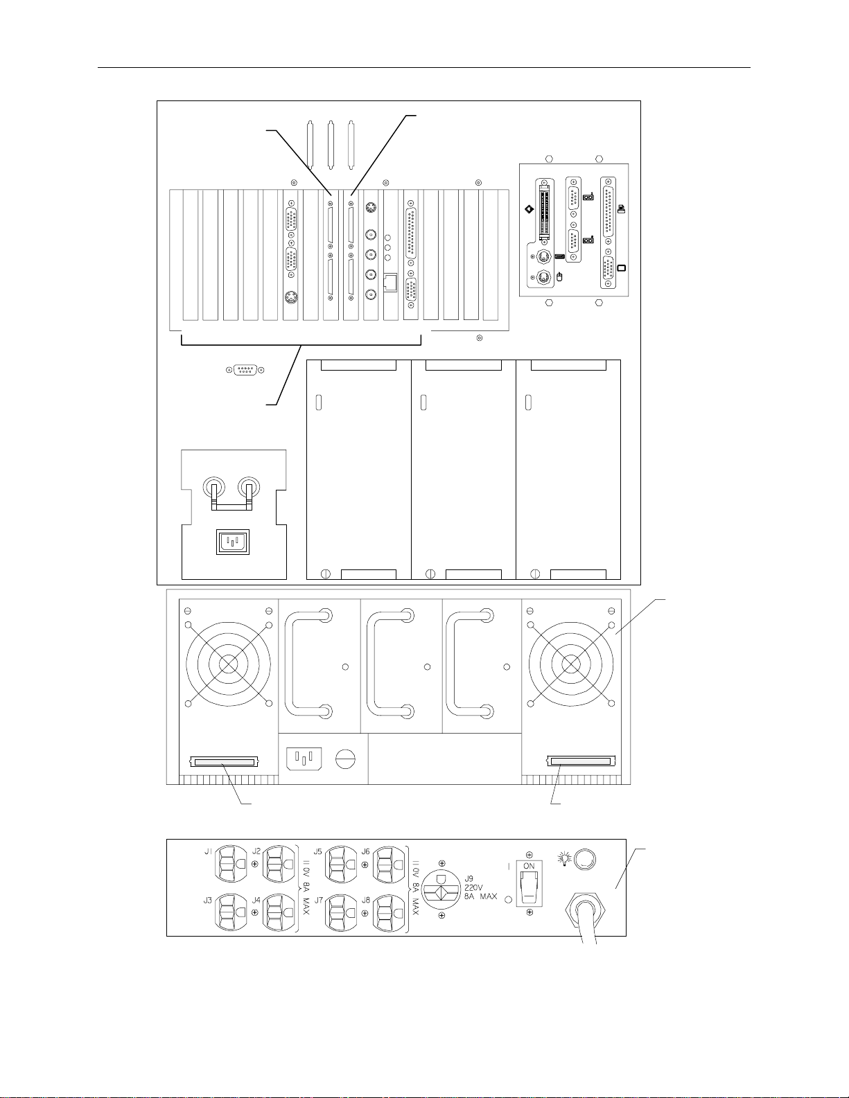
The following figure shows the slots and standard board connectors on the back of the base unit. Refer
to the documentation for each board for specific cable hookup procedures.
RAID
Controllers
RealiZm Z10T
StudioZ SDI Card
Ethernet Card
Sound Card
12 11 10 9 8 7 6 5 4 3 2 1 1234
PCI Slot s ISA Slots
Page 56
46
System Power Cord
To attach the system power cord:
1. Ensure the base unit circuit breaker switch is in the Off (down) position before attaching the power
cord to the system and wall outlet.
Circuit Breaker
Switch
(In Off Position)
2. Connect the power cord to the base unit and to the AC distribution box.
3. Connect the power cord from the AC distribution box to the wall outlet, type NEMA L14-20R or
IEC 309.
WARNING The wall outlet must be on a properly grounded branch circuit.
Page 57
Cable Handlers
To install cable handlers:
1. Extend the base unit to provide room in the back of the rack for installing the cable handlers.
2. On a rear mounting post, count 5 holes above the top of the base unit rail and attach a tinnerman
nut. Count an additional 4, 5, and 4 holes and attach tinnerman nuts. Refer to the following figure.
3. Attach the cable handler to the rail using four screws. The part of the cable handler that comes off
(for inserting cables) must face the rack walls. Refer to the following figure.
47
Cable
Handler
Base Unit
Rail
This side faces
rack wall
NOTE Most cables that attach to the system base unit must be inserted into one of the cable handlers. The
cable handlers allow the base unit to be extended without risk of damaging cables or pulling them out
of other devices. The following figure shows how the cables are inserted.
Page 58

48
These ends to the
devices
These ends to the
base unit
To route cables:
NOTE The base unit must be extended to insert cables into the cable handler.
1. Connect all the system power cords and data cables to the base unit and to the AC distribution box
or UPS.
2. Insert all cables that attach to the base unit (except for keyboard and mouse cables) into the cable
handler.
3. Additionally, there are cable ties and clamps along the rear mounting rails of the rack. Route
cables through these ties and clamps if necessary.
NOTE Cables that are attached to the base unit and connect to devices in another rack must also be inserted
into the cable handler.
4. After routing the cables into the cable handlers, fully extend the base unit to ensure there is enough
service loop in the cables.
Page 59

Additional Rack-mount Equipment
Additional equipment may be installed into the rack, provided the power requirements are within the
available limits of the installed AC distribution box.
CAUTION Refer to “Safety Precautions” and “Power Requirements” in Chapter 1 before installing additional
equipment.
WARNING If using non-Intergraph cables with the system, ensure that they are shielded and terminated on
both ends.
To install additional equipment into the rack:
1. Ensure that the installed AC distribution box can support the additional equipment.
2. Install the necessary mounting shelves or rails to support the equipment into available space. Use
tinnerman nuts for the shelves or rails.
3. Install the equipment, and place tinnerman nuts where the equipment will bolt into the rack.
Secure the equipment to the rack.
4. Connect the cables to the equipment and to the appropriate ports on the back of the base unit.
49
All cable ports on the base unit and other Intergraph equipment are keyed or molded to ensure proper
cable attachment. If a cable is not attaching easily, ensure that you are aligning the cable connector
correctly with the port.
Checking the Setup
Before starting the system, review the following items:
u
All hardware is properly and securely installed, and all RAID disk drives are installed in the
correct locations.
u
The cables are properly attached from the base unit to the InterRAID-8 cabinet, peripherals, and
extender.
u
The cables attached to the base unit are routed through the cable handler. Ensure there is enough
cable service loop to allow sliding devices to extend 31 inches.
u
The cables that run along the sides or top of the rack are installed in clips or ties to secure them in
place.
u
The power cord from the AC distribution box is attached to the correct wall outlet.
u
The base unit is retracted and secured to the rack with screws at each corner.
Starting the System
Go to the System Setup, delivered with the system, to start the system for the first time and
configure the operating system and system software.
Page 60

50
Page 61

4 Hardware Overview
This chapter shows front and rear views of the base unit, including major parts and assemblies. Under
each figure is a table that states the Intergraph part number of items called out in the figures. The
Reference Page column in the table guides you to the page in this document for specific information
about the part.
51
Page 62

52
A7
8
1
2
B
3
4
5
6
Find No.
Intergraph
Part No.
Description
Reference
Page
1 CFAB371F Front top cover n/a
2 MMSA4010 5.25-inch peripheral bracket n/a
3 CDSKxxx CD-ROM Drive 84
4 CDSK094 2 GB fixed disk drive (StudioZ RAX only) 85
4 CFAB558F Disk drive tray n/a
5 CFAB364F Airflow baffle n/a
6 MESAN160 Hot swappable system fan n/a
7 MMSA4070 3.5-inch drive bracket n/a
8 MESAM86 Combo drive 86
Page 63
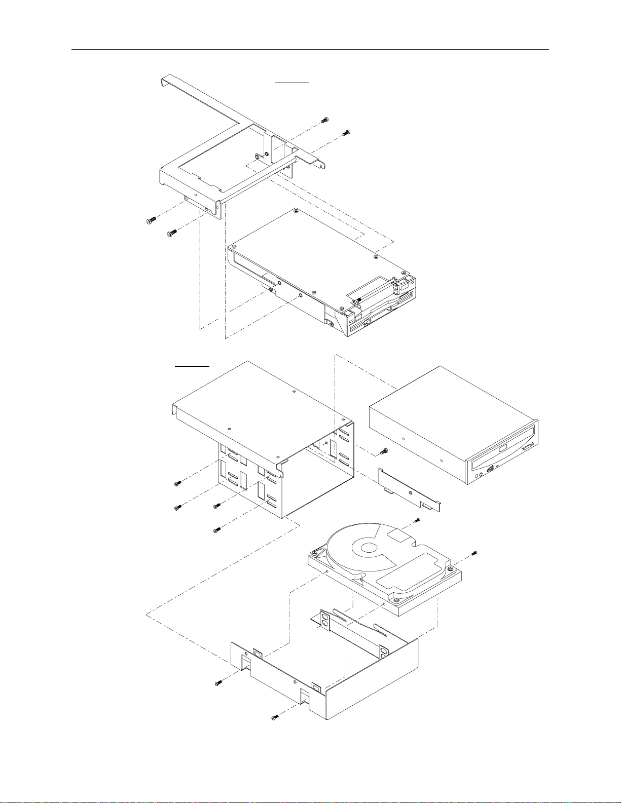
Detail A
r
MESAM86
53
MMSA4070
Detail B
MMSA401
CDSK132, o
CDSK156
CFAB253
CSK094
CFAB558
Page 64

54
2
1
3
4
A6
5
Find No.
Intergraph
Part No.
Description
Reference
Page
1 CFAB357F Cross bar support n/a
2 MSMT329 Processor board 53
3 CFAB374F LCD back plate n/a
4 MPCBD20 LCD board 71
5 CFAB370F RAID section door n/a
6 MESAN200 Internal RAID section 76
Page 65

Detail A
55
MMSA399
MSMT351
MCBL098
MSMT347
MSMT347
MSMT349
MSMT348
MSMT350
Page 66

56
3 4
1
5
6
Find No.
Intergraph
Part No.
Description
Reference
Page
1 CFAB354F Back top cover n/a
2 MSMT328 I/O connector board 68
3 MSMT330 I/O expansion board 58
4 MSMT331 or
Power distribution board 71
MSMT385
5 n/a AC receptacle, circuit breaker switch, AC filter,
enclosure
6 MPWS139 550 W power supply, hot swappable, redundant 79
7 CFAB348 I/O panel n/a
2
7
A
NOTE The power distribution board has two board stiffeners attached. The assembly number using
MSMT331 or MSMT385 is MESAN180.
Page 67

Detail A
57
CFAB348
MSMT328
Page 68

58
Page 69

5 System Hardware Information
This chapter contains technical information about the boards, and other hardware that comes standard
with the InterServe 650, 660 and StudioZ RAX systems. The following hardware items are described.
u
Processor board (MSMT329)
u
I/O expansion board (MSMT330)
u
I/O connector board (MSMT328)
u
LCD panel (MPCBD20)
u
Power Distribution board (MSMT331 or MSMT385)
u
Internal RAID Section (MESAN20)
u
Intruder Alert
u
Peripherals
u
System Fans
If your system includes any of the following hardware, refer to the documentation delivered with that
hardware for additional information:
59
u
RAID controller (CINF917)
u
InterRAID-8 cabinet (FDSK459/473/487/488)
u
100 Base-T Fast Ethernet card (CINF920)
u
InterSite Server Monitor (CINF029), InterServe only
u
Concentrator (FINF924 or FINF925), InterServe only
u
Uninterruptible Power Supply (MPWS144)
u
StudioZ card (MSMT297), StudioZ RAX only
u
RealiZm Z10T (MESAM96), StudioZ RAX only
u
Professional Audio sound card (CINF094), StudioZ RAX only
u
PC Extender (CINF033), StudioZ RAX only
Page 70

60
System Level Functional Diagram
AC In
Power
Distributi on ( AC
Box or UPS)
I/O Expansion
Board
(MSMT330)
I/O Connector
Board
(MSMT328)
Power
Supply
Keyboard
Mouse
Monitor
Serial
Ports
Parallel
Port
SCSI
Port
AC Filter
Circuit Breaker
Switch
Power
Supply
Power Distribution Board
(MSMT331 or MSMT385)
Intruder
Alert
Terminal
Block
Power
Supply
Processor
Board
(MSMT329)
System Fans
(MESAN160)
Combo Drive (MESAM86)
System Keyswitch
Internal RAID Section
(MESAN200)
LCD Board (MPCBD20)
CD-ROM Drive (CDSK132)
Fixed Disk Drive (CDSK094)
CDSK 094 for Studio Z RAX only.
Optional drive or empty in InterServe .
Part Page Part Page
Power distribution n/a Intruder Alert 90
Power distribution board (MSMT331
79 Keyboard n/a
or MSMT385)
I/O expansion board (MSMT330) 66 Monitor 89
I/O connector board (MSMT328) 76 System fans (MESAN16) n/a
Processor board (MSMT329) 61 Combo drive (MESAM86) 95
LCD Board (MPCBD20) 79 CD-ROM drive (CDSK132) 92
Internal RAID section (MESAN20) 84 Disk drive (CDSK094) 94
Page 71

Processor Board (MSMT329)
This section provides a functional diagram, memory subsystem description, address resources, and
board layout for the processor board. The MSMT329 provides the following functionality:
u
Processors - two or four Pentium Pro 200 MHz, each with 512 kB L2 cache (InterServe) or 256 kB
L2 cache (StudioZ RAX)
u
Intel Orion chipset - two PCI Bridge chips, Memory Controller, four Memory Interface chips.
u
Memory - up to 4 GB using 32Mx36 SIMMs
u
Flash EEPROM - contains Basic Input/Output System (BIOS)
Functional Diagram
61
GTL Bus
Term
PCI
VRM VRM
CPU
CPU
VRM VRM
Local Bus
OPB
82454
P6 Processor External Bus
OMC-DC
82453
Memory
PCI
Local Bus
OPB
82454
OMC-DP
82452
MIC
CPU
CPU
GTL Bus
Term
VRM (Voltage Regulator Module)
CPU (Central Processing Unit, Pentium Pro)
OPB (Or ion PCI Bridge)
OMC (Orion Memory Controller)
MIC (Memory Interface Chip)
Page 72

62
Memory Subsystem Description
The processor board uses industry-standard 60 ns, fast page mode, 72 pin (parity pinout) SIMMs. The
board has 32 SIMM sockets.
u
There are four banks in the memory subsystem system, each banks containing eight sockets. Bank
0 is half-populated (four SIMMs) for base memory configurations (128 MB or 256 MB). The first
upgrade must fill the second half of Bank 0, and subsequent upgrades must completely fill each
bank sequentially from Bank 1 to 3. All SIMMs in the memory subsystem must be the same size.
u
InterServe 650 and 660 supports three SIMM sizes: 8Mx36 (32 MB), 16Mx36 (64 MB), and
32Mx36 (128 MB). Base systems with 128 MB (four 8Mx36 SIMMs) can be expanded with
8Mx36 SIMMs, for a maximum memory support of 1 GB. Base systems with 256 MB (four
16Mx36 SIMMs) can only be expanded with 16Mx36 SIMMs, for a maximum memory support of
2 GB. Base systems with 512 MB (four 32Mx36 SIMMs) can only be expanded with 32Mx36
SIMMs, for a maximum memory support of 4 GB. Only four SIMMs in Bank 0 are installed for
base memory.
u
StudioZ RAX supports two SIMM sizes: 8Mx36 (32 MB), and 16Mx36 (64 MBBase systems
with 256 MB (eight 8Mx36 SIMMs) can be expanded with 8Mx36 SIMMs, for a maximum
memory support of 1 GB. Base systems with 512 MB (eight 16Mx36 SIMMs) can be expanded
with 16Mx36 SIMMs, for a maximum memory support of 2 GB. Eight SIMMs (in Bank 0) are
installed for base memory.
NOTE Systems with BIOS 7640A.ROM support up to 2 GB memory. Systems with BIOS 7640B.ROM or later
support up to 4 GB memory. If your system has version A of the BIOS, you can reprogram the BIOS to
version B. Refer to the
System Setup
for instructions to reprogram the BIOS.
Memory is organized into words, interleaves, and rows.
u
Each SIMM generates either the low word (bits 35 to 0) or the high word (bits 71 to 36) of a
72-bit doubleword (8 bits of which are ECC bits) depending on installed location. The low word
and high word sections are split on each side of the board as shown in the following figure. The
high word is called word 1 or W1, and the low word is called word 0 or W0. Due to the design, if
a row in W0 is populated, the same row in W1 (and vice versa) must also be populated for proper
operation. The same memory density SIMM must be used in the row.
u
Rows are numbered 0 through 7. Starting at the center of the board and moving out, the first 4
SIMMs on both sides are on row 0 (rows 0 and 1 if the SIMMs are double-sided). The next four
SIMMs are on row 2 (and 3 if double-sided), and so on, through the last (outermost) four SIMMs
on each side of the board, which are on row 6 (and 7 if double-sided).
u
Within each row there are four interleaves, designated i0 through i3. Base InterServe
configurations populate i0 and i1 of Row 0/1 for two-way interleave. Base StudioZ RAX
configurations populate i0, i1, i2, and i3 of Row 0/1 for four-way interleave. When upgrades are
installed, all four interleaves of the adjacent rows are populated, yielding four-way interleave for
all installed memory. The correlation between banks and rows is:
Bank 0 Rows 0/1 (i0, i1, i2, i3)
Bank 1 Rows 2/3 (i0, i1, i2, i3)
Bank 2 Rows 4/5 (i0, i1, i2, i3)
Bank 3 Rows 6/7 (i0, i1, i2, i3)
Page 73

63
Word 1
Rows 0/1
i0i1i2i3i0i1i2i3i0i1i2i3i0i1i2i3 i0i1i2i3 i0i1i2i3 i0i1i2i3 i0i1i2i3
Bank 0 = Rows 0/1 Bank 2 = Rows 4/5
Bank 1 = Rows 2/3 Bank 3 = Rows 6/7
Word 0
Rows 2/3Rows 6/7 Rows 0/1Rows 2/3Rows 4/5 Rows 6/7Rows 4/5
The following table shows the correlation between interleaves, words, rows and the socket J numbers. The ECC
Memory driver program, used to detect and diagnose memory problems, specifies SIMM locations by interleave and
row, but does not distinguish which word the error occurred in. Refer to the System Introduction for ECC Memory
driver information.
Row 0
Row 1
Row 2
Row 3
Row 4
Row 5
Row 6
Row 7
i0
i1 i2 i3
W1 W0 W1 W0 W1 W0 W1 W0
J36 J40 J35 J39 J34 J38 J33 J37
J36 J40 J35 J39 J34 J38 J33 J37
J32 J44 J31 J43 J30 J42 J29 J41
J32 J44 J31 J43 J30 J42 J29 J41
J28 J48 J27 J47 J26 J46 J25 J45
J28 J48 J27 J47 J26 J46 J25 J45
J24 J52 J23 J51 J22 J50 J21 J49
J24 J52 J23 J51 J22 J50 J21 J49
Page 74

64
NOTE Since ECC Memory driver does not distinguish whether an error occurred in word 0 or word 1 of a
given interleave, both words (i.e. both SIMMs) have to be changed to correct a single-bit problem.
Forexample, correcting single-bit errors that are occuring in interleave 0, row 0, requires replacing
SIMMs in J36 and J40.
An additional diagram showing socket JXX numbers is on page 65.
Address Resources
Memory Address Map
The following table lists the memory address map assignments.
Memory Address Range
Description (Size)
0_00000000 - 0_0009FFFF System Board Memory (640K)
0_000A0000 - 0_000BFFFF Video Memory (128K)
0_000C0000 - 0_000C7FFF Video ROM (32K)
0_000C8000 - 0_000CFFFF SCSI ROM (32K)
0_000D0000 - 0_000DFFFF Available I/O Adapter ROM (64K)
0_000E0000 - 0_000FFFFF System BIOS ROM (128K)
0_00100000 - 0_7FFFFFFF System Board Memory (2047M)
0_80000000 - 0_AFFFFFFF Unused
0_B0000000 - 0_DFFFFFFF Typical PCI Adapter Usage
0_E0000000 - 0_FEBFFFFF Unused
0_FEC00000 - 0_FEC003FF SIO.A APIC Registers (1K)
0_FEC00400 - 0_FEC007FF I/O APIC Registers (1K)
0_FEC00800 - 0_FEDFFFFF Unused
0_FEE00000 - 0_FEE00FFF Processor APIC Registers (4K)
0_FEE01000 - 0_FFF7FFFF Unused
0_FFF80000 - 0_FFFDFFFF Reserved
0_FFFE0000 - 0_FFFFFFFF System BIOS ROM - shadow
0_FFFE0000 - F_FFFFFFFF Unused
Page 75

Board Layout
VRM 3
65
Sideband Connector PCI Connector 1PCI Connector 0
CPU 2CPU 0CPU 1CPU 3
VRM 0
J21
VRM 1
Memory Sockets
PCI Bridge
OPB 0
(Primary
Compatibility)
82454
J36 J37 J52
PCI
Bridge
OPB 0
(Primary
Auxiliary)
82454
J19 J20J17 J18
Memory Sockets
VRM 2
Lithium Battery
Two PCI bridge chips (Intel OPB 0 82454) provide high-bandwidth PCI compatibility for the system.
One bridge chip supports PCI bus 0 (Primary Compatibility bus), and is the path by which processors
have access to all PC compatibility devices such as the ISA bus, BIOS PROM, and graphics controller.
PCI bus 0 supports slots 1 through 3. PCI bus 1 (Primary Auxiliary bus) is also bridged directly off the
P6 bus by the second 82454 and supports PCI slots 4 through 7. For best system performance, highbandwidth devices that efficiently use PCI burst protocols to transfer data as bus masters should reside
on PCI bus 1 or 2 (slots 1 though 7).
Lithium Battery
The Lithium battery on the processor board provides power to the real time clock, which the power
distribution board uses to display the current time on the LCD screen. As long as the system is running,
the batteries are not used to sustain the information. If the battery fails, the LCD screen will not display
the date and time. You can replace the failed battery following these instructions:
Page 76
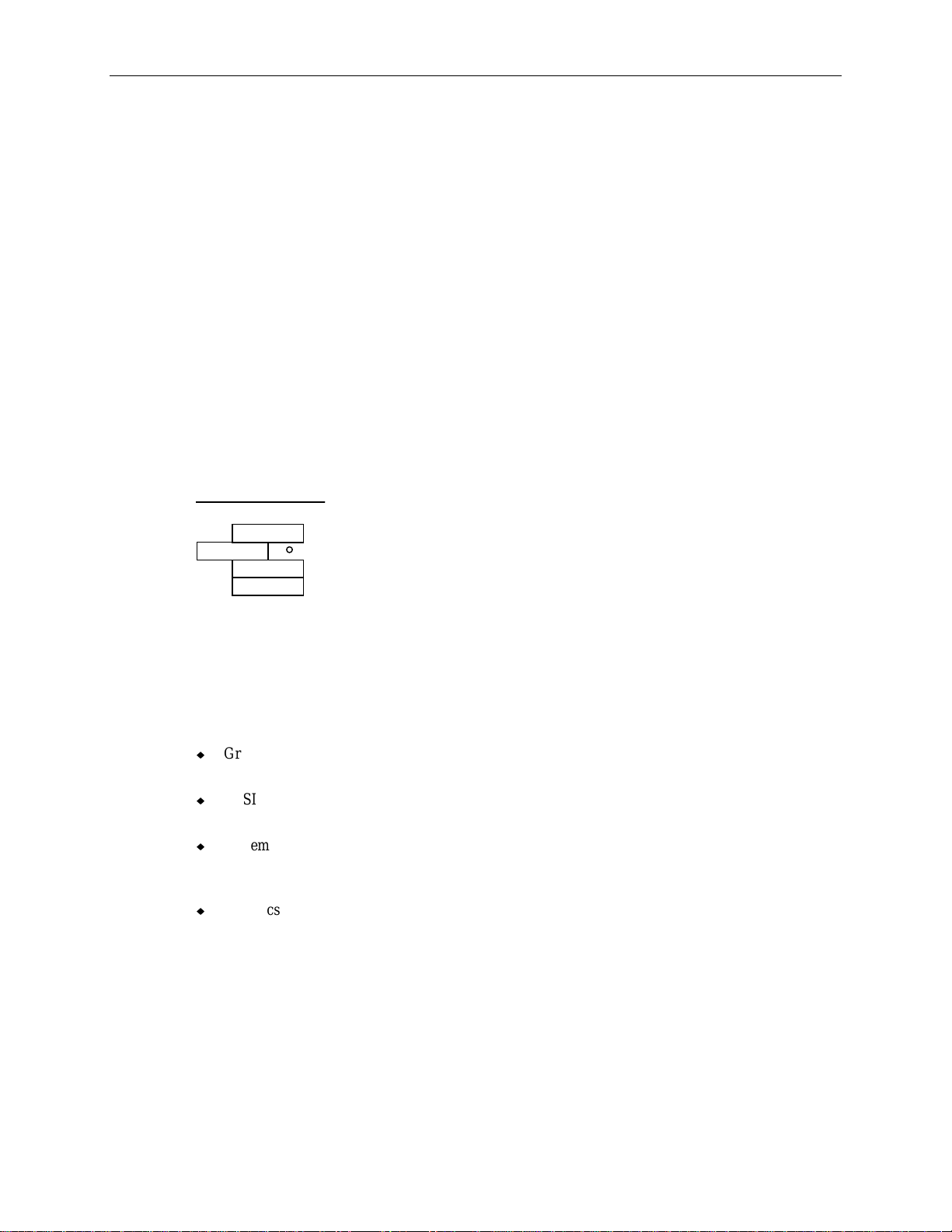
66
WARNING There is a danger of explosion if the battery is incorrectly replaced.
WARNING Replace the battery with the same or equivalent type only, as recommended by the
manufacturer. Dispose of used batteries according to the manufacturer’s instructions.
To replace the Lithium battery:
1. Remove the peripheral drives. It is not necessary to disconnect their attached cables.
2. Carefully remove the discharged battery by grasping it firmly and lifting upward.
3. Install the new battery in the same orientation as the discharged battery.
4. Replace the peripherals.
5. Dispose of the discharged battery according to the manufacturer’s instructions.
CPU Frequency Jumper Connectors
The following figure shows the detail for the default jumper settings for the 200 MHz processors. The
processors will not work properly if the jumper settings are changed. All four jumpers are set the same.
Jumper Detail
(J17 - J20)
A1 B1
J17 = CPU 3
J18 = CPU 1
J19 = CPU 0
J20 = CPU 2
I/O Expansion Board (MSMT330)
This section providesa functional diagram, the I/O address ranges, DMA channels, board layout, and
component descriptions for the I/O expansion board. The MSMT330 provides the following
functionality:
u
Graphics - integrated G95 (Matrox MGA-2064W) with 2 MB of Window RAM (frame buffer
video memory)
u
SCSI - integrated Adapted 7860 Ultra SCSI controller supports internal CD-ROM drive, disk drive
(for StudioZ RAX), and external 8-bit SCSI expansion
u
System I/O - integrated Standard Microsystems Corporation FDC37C932 Super I/O Controller
supports PS/2 mouse, keyboard and floppy disk drive peripherals, includes Real Time Clock and
Non-Volatile RAM, and provides serial and parallel port capabilities
u
Graphics - integrated Matrox MGA-2064W graphics accelerator, Texas Instruments TVP3026
palette DAC, and 2 MB of Window RAM (WRAM). The graphics subsystem provides single
screen support, several 2D resolutions, and video playback acceleration. Refer to “Monitors” on
page 89 for monitor resolution information.
Page 77
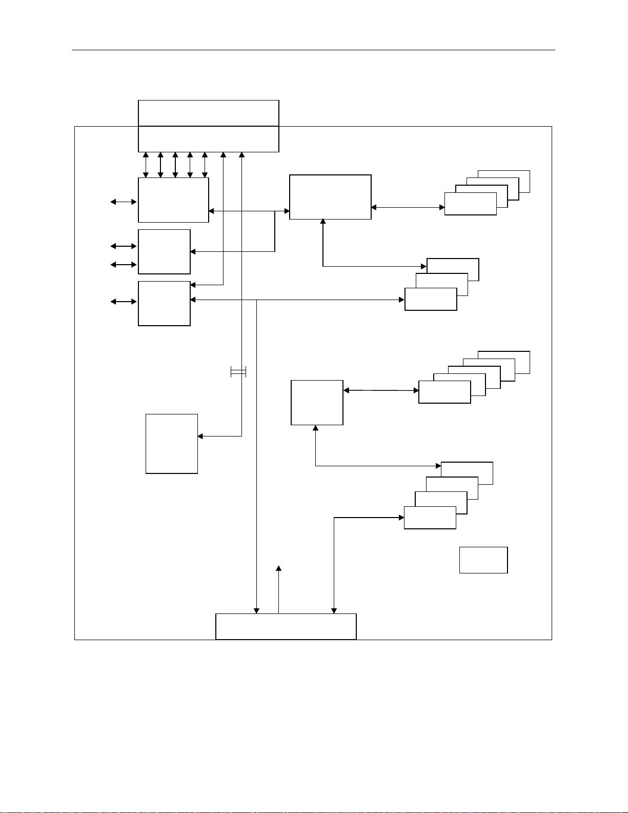
Functional Diagram
y
p
(Secondary)
I/O Connector Board
Super I/O
4
Controller
FDC37C932
MSMT328
I/O Interface
111098765
ISA Bus
82379AB
PCI - ISA Br idge
ISA Bus
ISA Slot 1
67
4
3
2
3
2
1
Cable
Buffers
Ultra SCSI
Controller
AIC-786-
VGA Video
Enable/Disable
2-
in header
PCI Local Bus
(Compatibility)
DED 21050
PCI Local Bus
(Compatibility)
PCI Bus
PCI Slot 1
PCI Slot 8
3
2
12
11
10
9
PCI - PCI
Bridge
Video
Controller
MGA-
PCMCIA
2064W
PCI Local Bus
(Auxiliary)
7
6
5
PCI Local Bus
(Compatibility)
PCI Slot 4
PCI Local
Control
Signal
Bus
Bus
(Auxiliar
System Board Interface
1 = To SCSI connector 5 = To Parallel port 9 = To Keyboard port
2 = To PCMCIA connector 6 = To Serial port 10 = To SCSI port
3 = To PCMCIA connector 7 = To Serial port 11 = To Video port
4 = To Floppy connector 8 = To Mouse port
ID
EEPROM
)
Page 78
68
I/O Addresses
The primary system I/O devices are:
u
Adaptec AIC-7860 Ultra SCSI
u
DEC 21050 PCI-to-PCI Bridge
u
Intel 82093AA I/O Advanced Programmable Interrupt Controller (I/O APIC)
u
Intel 82454 PCIset Orion PCI Bridge (OPB)
u
Intel 82452, 82453 PCIset Orion Memory Controllers (OMC)
u
Intel 82379AB System I/O-APIC PCI-to-ISA Bridge
u
Matrox MGA-2064W G95 graphics
u
Standard Microsystems FDC37C932 Super I/O Controller
The following table lists a small subset of the reserved I/O addresses used in the system.
Address Range
0000 - 000F DMA Controller 1 (DMA1)
Description Address Range Description
0278 - 027F Parallel Port LPT2
registers
0020 - 0021 Interrupt Controller 1
02E8 - 02EF Serial Port COM4
(INT1)
0022 - 0023 System Configuration 02F8 - 02FF Serial Port COM2
(FDC37C932)
0040 - 0043 Timer Counter 1 0370 - 0377 Secondary Floppy Disk
Controller
0060 - 0064 Keyboard (FDC37C932),
NMI Status
0070 - 0071 Real Time Clock
(FDC37C932)
0378 - 037F Parallel Port LPT1
(FDC37C932)
03B0 - 03BF Monochrome
Display/Printer Adapter
0078 - 007B BIOS Timer 03D0 - 03DF Color/Graphics Monitor
Adapter (CGA/MCGA)
0080 - 0091 DMA page registers 03E8 - 03EF Serial Port COM3
0092 - 0092 System Control Port 03F0 - 03F7 Floppy Controller
(FDC37C932)
0093 - 009F DMA page registers 03F8 - 03FF Serial Port COM1
(FDC37C932)
00A0 - 00A1 Interrupt Controller 2
0480 - 048F DMA high page registers
(INT2)
00B2 - 00B3 Advanced Power
Management Control/Status
04D0 - 04D1 Interrupt Controller Edge
Level Control
Ports
00C0 - 00DF DMA Controller 2 (DMA2)
registers
00F0 - 00F1 Clear/Reset Math
0CF8 - 0CFF PCI Configuration Space
Access
B000 - DFFF Typical PCI Adapter Usage
Coprocessor
01F0 - 01F8 IDE Hard Disk Controller
(FDC37C932)
Page 79
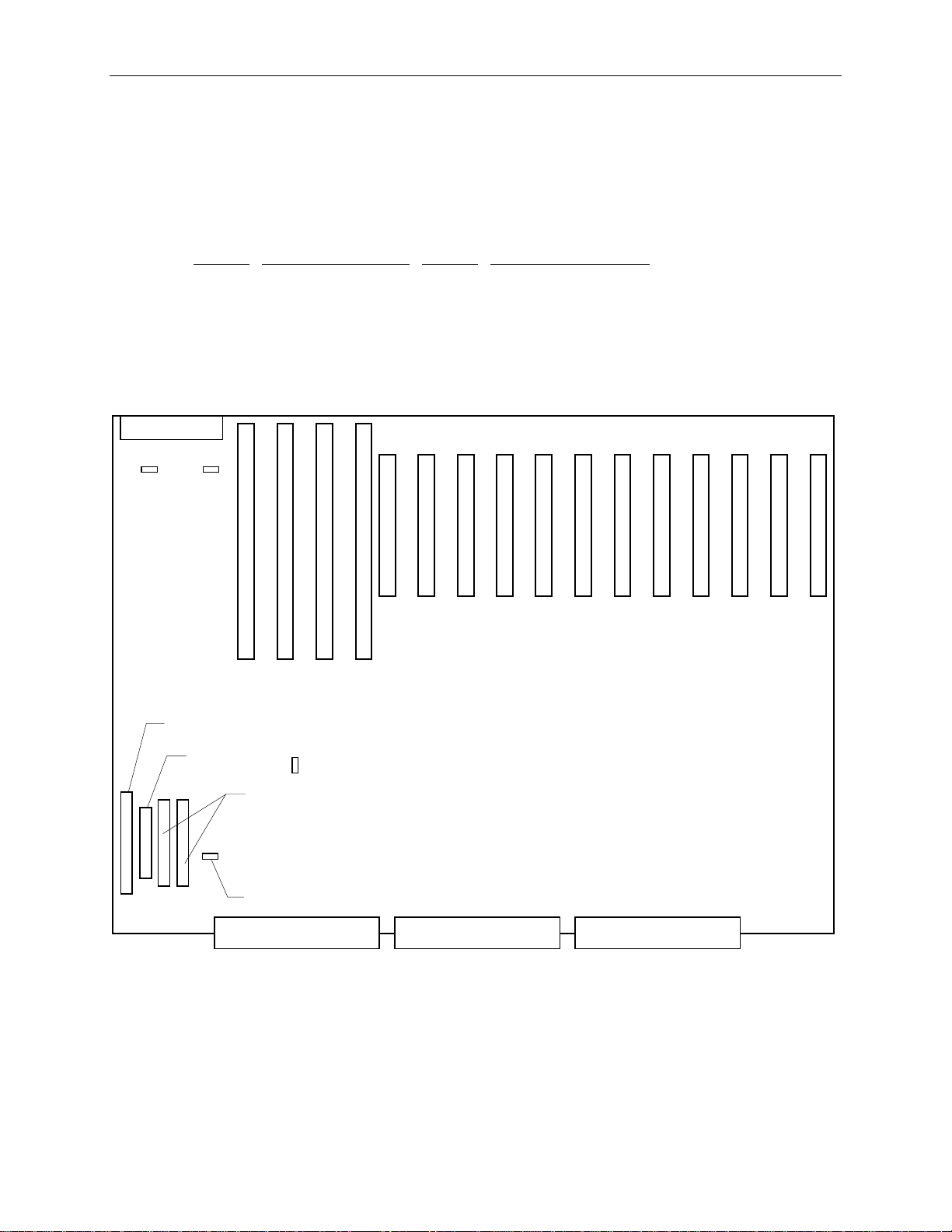
DMA Channels
The system board uses Direct Memory Address (DMA) channels to exchange data without accessing
the CPU. Some channels are assigned for specific use by the system, as defined below. Each DMA
channel appropriates full 32-bit processing. For an ISA bus, channels 0 through 3 are 8-bit and
channels 4 through 7 are 16-bit channels.
69
DMA
0 Spare 4 Cascade input for 0-3
1 Spare 5 Spare
2 Floppy I/O Controller 6 Spare
3 Parallel Port 7 Spare
Board Layout
J19 J20
ISA 4 3 2 1
SCSI J26
Assignment DMA Assignment
1 2 3 4 5 6 7 8 9 10 11 12
PCI
PCI Bus 0 = 1 - 3
PCI Bus 1 = 4 - 7
PCI Bus 2 = 8 - 12
Floppy J29
J25
PCMCIA
J27, J28
Speaker J30
Sideband Connector PCI 1 ConnectorPCI 0 Connector
Page 80

70
Standard Board Placement
InterServe 650, 660
Slot
RAID Controller (CINF917) PCI 7
100 Base-T Fast Ethernet (CINF920) PCI 2
InterSite Server Monitor (CINF029) ISA 4
StudioZ RAX
Slot
RAID Controller (CINF917) PCI 7
RAID Controller (CINF917) PCI 6
RealiZm Z10T (MESAM96) PCI 5 and 4
StudioZ (MSMT297) PCI 3
100 base-T Fast Ethernet (CINF920) PCI 2
NOTE In StudioZ RAX, the RAID controller in PCI slot 6 connects to the InterRAID-8 cabinet.
Jumper Connectors
Connector
J19 On
J20 On
Jumper Result
Clears Real Time Clock and CMOS data
Off
Default
Clears the BIOS Password
Off
Default
J25 On
Off
Disables VGA display mode
Enables VGA display mode (default)
Cable Routing and Pinouts
From
Cable To
J26, SCSI MCBL102A CDSK094 and CDSK132
J27, ISA Bus (PCMCIA) MCBL084A MESAM86, J6
J28, ISA Bus (PCMCIA) MCBL084A MESAM86, J3
J29, Floppy MCBL106A MESAM86, J2
J30, speaker MCBLW660 Speaker
NOTE CDSK094 (2 GB fixed disk drive) is used only in StudioZ RAX.
Page 81

J26, MCBL102A, SCSI
71
Pin
26 CD0 33 CD7 46 MSG
27 CD1 34 CD Parity 47 SCT
28 CD2 38 TPWR 48 CMD
29 CD3 41 ATTN 49 REQ
30 CD4 43 BSY 50 I/O
31 CD5 44 ACK Remaining Ground
32 CD6 45 RST
J27, MCBL084A, PCMCIA ISA Bus
Pin
1 IRQ15 15 SD+(0) 28 Ground
2 IRQ14 16 SD+(1) 29 RSTDRV
3 IRQ10 17 SD+(4) 30 Ground
4 IRQ3 18 SD+(5) 31 SA+(6)
5 IRQ7 19 MEMW- 32 SA+(7)
6 IRQ9 20 MEMR- 33 SA+(10)
7 IOCS16- 21 SA+(17) 34 SA+(11)
8 Ground 22 SA+(18) 35 SA+(14)
9 IOCHRDY+ 23 SA+(21) 36 SA+(15)
10 Ground 24 SA+(22) 37 BALE
11 SD+(14) 25 SA+(1) 38 IOR12 SD+(15) 26 Ground 39 D7BUFDIR
13 SD+(11) 27 SA+(3) 40 PWR_DWN
14 SD+(10)
Signal Pin Signal Pin Signal
Signal Pin Signal Pin Signal
J28, MCBL084A, PCMCIA ISA Bus
Pin
Signal Pin Signal Pin Signal
1 Spare 15 SD+(2) 28 Ground
2 IRQ11 16 SD+(3) 29 SA+(4)
3 IRQ4 17 SD+(6) 30 SA+(5)
4 IRQ5 18 SD+(7) 31 SA+(8)
5 0WS- 19 SA+(19) 32 SA+(9)
6 Ground 20 SA+(20) 33 SA+(12)
7 MEMCS16- 21 SA+(23) 34 SA+(13)
8 Ground 22 SBHE- 35 SA+(16)
9 SPKR- 23 SA+(0) 36 AEN
10 Ground 24 Ground 37 IOW11 SD+(13) 25 SA+(2) 38 Ground
Pin Signal
Pin Signal Pin Signal
Page 82

72
12 SD+(12) 26 Ground 39 LOBUFDIR
13 SD+(9) 27 ISA BCLK 40 HIBUFDIR
14 SD+(8)
J29, MCBL106A, Floppy
Pin
Signal Pin Signal Pin Signal
2 RPM 14 DRV0- 26 TRK04 No connect 16 MTR1- 28 WRPRT6 DRATE0 18 DIR 30 RDATA8 INDEX- 20 STEP- 32 HDSEL
10 MTR0- 22 WDATA- 34 DSKCHG
12 DRV1- 24 WGATE-
NOTE All odd-numbered pins of J29 are connected to ground, except pin 29 (MID1) and pin 33 (MID0).
J30, MCBLW660, Speaker
Signal Color
Pin
1 + 5.1 V Red
2 Ground White
Page 83

Component Descriptions
The IO Expansion Board provides PCI and ISA expansion slots. It also has the graphics, non-RAID
SCSI, mouse, keyboard, serial port, parallel port, and floppy controllers, as well as the PC
compatibility hardware (BIOS PROM, NVRAM, RTC) and interrupt logic.
Expansion Connector
Super I/O
Controller
Lithium Battery
Palette
DAC
73
PCI-to-ISA
Bridge
WRAM
Graphics Accelerator
SCSI Contr oller
PCI-to-PCI
Bridge
Graphics Accelerator
The graphics accelerator (Matrox MGA-2064W) interfaces to the system board through the PCI bus.
This accelerator supports all of the standard VGA graphics modes in addition to native modes capable
of resolutions up to 1600 x 1200. The frame buffer interface is 64 bits wide and is clocked at 100
MHz. Color depths of 4, 8, 16, 24, and 32 bits are supported, allowing a resolution of 1280 x 1024 (24
bit color depth) in only 4 MB of frame buffer memory. Features such as bit block transfer (BitBlt),
Line Draws, and Fills provide hardware acceleration for Windows. Video playback is accelerated
through scaling and YUV to RGB color space conversion.
StudioZ RAX uses the MGA 2064W only as a video boot device. Graphics capabilities for StudioZ
RAX are handled by the Z10T card (MESAM96) and the StudioZ SDI card (MSMT297). Refer to the
appropriate documentation for descriptions of those graphics cards.
Page 84

74
Palette DAC
The palette DAC operates up to 175 MHz and converts the digital RGB data in the frame buffer to
analog signals for the monitor. The device includes two fully programmable phase-locked loop clock
sources for both the memory clock and the pixel clock.
Window RAM
Window RAM (WRAM) is the video memory used by the MGA-2064W. The graphics frame buffer
consists of two 256K x 32 WRAM components for 2 MB of video memory. WRAM is a dual-ported
video memory specially designed to accommodate common drawing functions, offering higher graphics
performance at a lower cost than standard Video RAM.
Starting with 2 MB WRAM, a 2 MB or 6 MB WRAM mezzanine module can be added for improved
video performance. 8 MB of WRAM is the maximum amount configurable. Memory above 2 MB
increases the number of colors available at each resolution, enabling you to work in true color mode at
higher resolutions. Increased WRAM also improves color acceleration by providing extra caching
memory for storing off-screen fonts and images.
SCSI Controller
The SCSI controller is the Adaptec Ultra SCSI Adapter (AIC-7860), which provides a single-ended bus
for SCSI-1, Fast SCSI-2, and Ultra SCSI devices. The SCSI bus is dedicated to the hard disk drives
and CD-ROM drive. The SCSI bus actively terminates on the system board and at the end of the
internal SCSI cable. The AIC-7860 supports low-speed devices to allow legacy SCSI devices to be
used with the system. By default, the controller functions in Fast SCSI-2 mode rather than Ultra mode.
Super I/O Controller
The I/O Expansion Board utilizes a Standard Microsystems Corporation (SMC) Super I/O Controller
(FDC37C932) to integrate mouse, keyboard, serial, parallel (multi-mode), floppy (2.88 MB), and RealTime Clock (RTC) functions into one chip.
The FDC37C932 supports four serial ports via two external port connectors (COM 1 and COM 2).
COM1 can be configured as COM1 or COM3; COM2 can be configured as COM2 or COM4. The
serial ports use the system I/O addresses shown below.
Port
COM1 3F8-3FF IRQ4
COM2 2F8-2FF IRQ3
COM3 3E8-3EF IRQ4
COM4 2E8-2EF IRQ3
The addresses for each serial port can be configured in AMIBIOS Setup, as described in the System
Setup. Do not assign more than one device to the same COM port number. Serial port problems occur
because a serial port and another device are assigned to the same COM number. The system and the
connected serial device must be set to the same communications parameters (baud rate, parity, number
of data bits, and number of stop bits). Refer to the serial device documentation for information about
setting these parameters.
Addresses Interrupts
Page 85

The parallel port functionality of the FDC37C932 include the following modes:
u
Normal mode (or Compatibility mode) - an industry-standard parallel interface mode. Normal
mode provides an asynchronous, byte-wide forward channel (host to peripheral), and is the base
mode common to all compliant interfaces.
u
SPP mode (or Byte or Bi-Dir mode) - compatible with IBM PS/2 hosts. SPP is an asynchronous,
byte-wide reverse channel (peripheral to host) mode using the eight data lines of the interface for
data, and the control/status lines for handshaking. Transfer direction is controlled by the host
when the peripheral and the host both support bi-directional use of data lines.
u
EPP mode - provides an asynchronous, byte-wide, bi-directional channel controlled by the host
device. This mode also provides separate address and data cycles over the eight data lines of the
interface. EPP increases the data transfer performance to 2 MB per second while retaining
backward compatibility with existing AT and PS/2 compatible interfaces.
u
ECP mode - similar to EPP, providing an asynchronous, byte-wide, bi-directional channel
controlled by the host device. Additionally, ECP implements a control line to distinguish between
command and data transfers. A command may optionally be used to indicate single byte data
compression or channel address. Other ECP mode features include:
−
Supports 2 MB per second data transfer rate
−
High performance, half duplex, forward and reverse channel
75
−
Interlocked handshake for fast, reliable data transfer
−
Channel addressing for low-cost peripherals
−
Link and data layer separation
−
Active output drivers and adaptive signal timing
−
Peer-to-peer capability
The addresses and interrupts used by the external parallel port can be assigned in AMIBIOS Setup.
Refer to the System Setup for information to configure the ports. The parallel port addresses and
interrupts are shown in the following table.
Port
Address Interrupt
LPT1 378-37A IRQ7 or IRQ5
LPT2 278-27A IRQ7 or IRQ5
LPT3 3BC-3BE IRQ7 or IRQ5
Expansion Connector
The expansion connector carries signals from SCSI, Super I/O, and graphics controllers to the I/O
connector board (MSMT328) for external devices.
PCI-to-ISA Bridge
The Intel 82379AB System I/O-APIC (Advanced Programmable Interrupt Controller) bridges the ISA
bus off the Primary Compatibility PCI bus (PCI bus 0). The 82379AB supports all four ISA expansion
slots.
Page 86
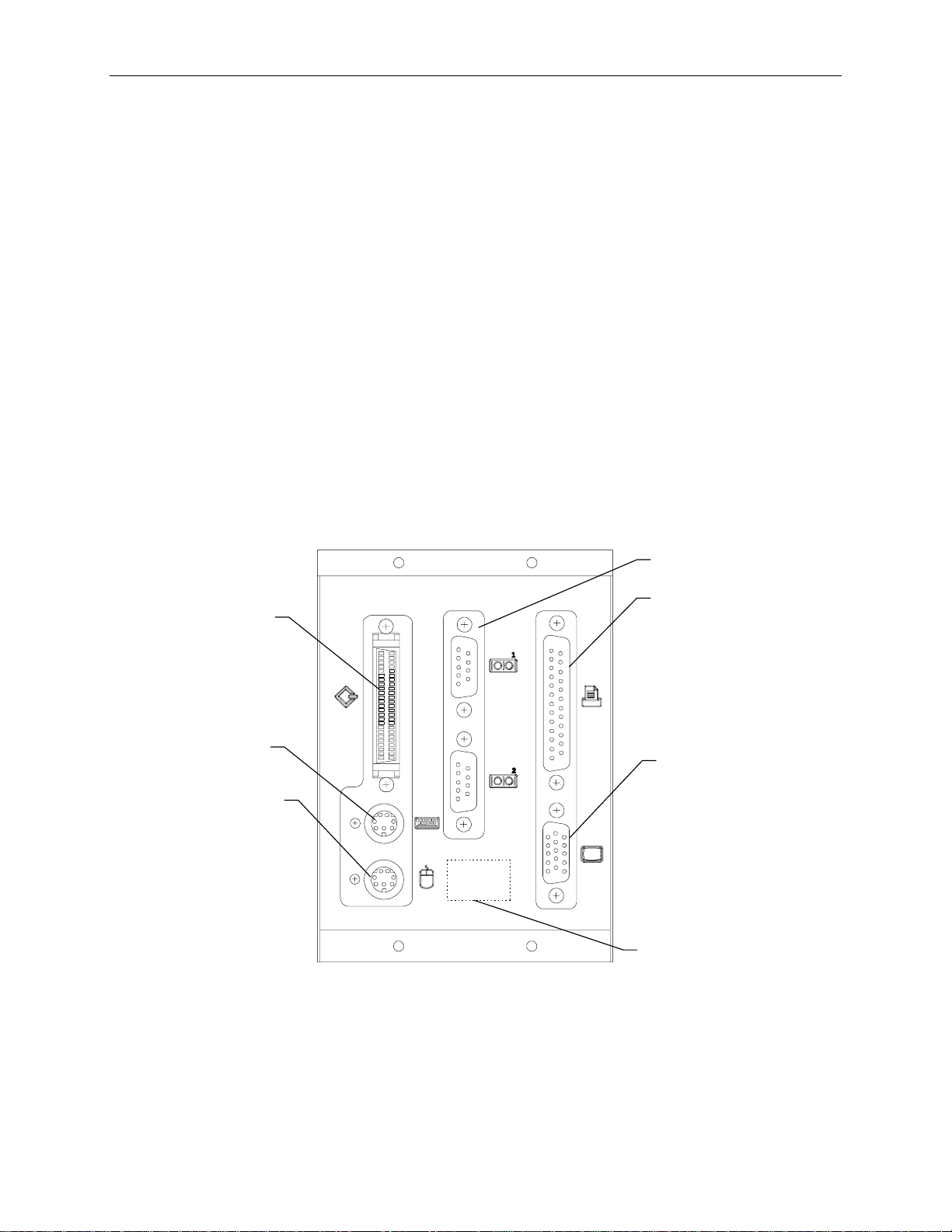
76
PCI-to-PCI Bridge
The DEC 21050 PCI-to-PCI bridge supports the PCI bus 2 (also known as Secondary Auxiliary),
which is bridged off PCI bus 1. PCI bus 2 includes the expansion slot 8 through 12. Refer to “PCI
Bridge” on page 65 for a description of PCI bus 0 and PCI bus 1.
Lithium Battery
The Lithium battery on the I/O expansion board provides power to the CMOS chip (which stores the
BIOS and the AMIBIOS Setup program) and real time clock. If the battery fails or if the voltage is
low, the message “Battery voltage low” displays during system startup, or the system date and time
information will not display. The battery on the MSMT330 board is not replaceable. If the battery
fails, the board must be replaced.
I/O Connector Board (MSMT328)
The I/O Connector Board plugs into the I/O Connector provided by the I/O Expansion Board. This
panel provides all the external connections required by the various components integrated into the I/O
Expansion board.
Board Layout
Keyboard
Port
Mouse Port
SCSI
Port
Serial Por t s
Parallel
Port
Video Port
Flas h EEPROM
(Side 2)
Page 87

SCSI Port
The SCSI port is used for data storage devices such as optical jukeboxes. The AIC-7860 is the
system’s SCSI controller. All SCSI devices connected to the SCSI port interface to the controller.
Refer to “SCSI Controller” on page 74 for more information.
Certain restrictions are applied for the number and type of SCSI devices, and cables lengths used for
the devices. Refer to the section “Adding External Peripherals” in Chapter 7 for more information.
Refer to page 71 for the SCSI pinout. See table “J26, MCBL102A, SCSI.”
Keyboard port, mouse port
The keyboard and mouse ports are PS/2 style, 6-pin ports. They are not interchangeable.
Refer to page 74 for information about the mouse and keyboard functions of the FDC37C932
controller.
77
J5 Keyboard
Pin Signal Pin Signal
1 KDATA 1 MDATA
2 Spare 2 Spare
3 Ground 3 Ground
4 VCC 4 VCC
5 KCLK 5 MCLK
6 Spare 6 Spare
Serial Ports
The serial ports (also referred to as RS-232 asynchronous communications ports, or COM
ports) can connect modems, printers, peripherals and other computers to the system. The serial ports
(labeled 1 and 2) are 9-pin, male DB9 connectors. If connecting a serial device with a 25-pin DB25
connector, use a 25-pin to 9-pin adapter cable to mate with the serial port on the system. Only shielded
cables should be used with the serial ports.
Refer to page 74 for information about the serial port functionality of the FDC37C932.
COM1/COM3
J6 Mouse
COM2/COM4
Pin Signal Pin Signal
1 COM1 DCD 1 COM2 DCD
2 COM1 RD 2 COM2 RD
3 COM1 TD 3 COM2 TD
4 COM1 DTR 4 COM2 DTR
5 Ground 5 Ground
6 COM1 DSR 6 COM2 DSR
7 COM1 RTS 7 COM2 RTS
Pin
Signal Pin Signal
Page 88

78
8 COM1 CTS 8 COM2 CTS
9 COM1 RI 9 COM2 RI
Parallel Port
The parallel port is used almost exclusively for printers, but is compatible with any peripheral
device designed to interface with a standard Centronics-type parallel port. The FDC37C932 is the
system’s parallel controller, among other things. The FDC37C932 supports a multi-mode bidirectional parallel port. Only shielded cables should be used with the parallel port (DB-25).
Refer to page 74 for information about the parallel port functionality of the FDC37C932.
Pin
1 STB 10 ACK
2 Data 0 11 Busy
3 Data 1 12 Paper Empty
4 Data 2 13 Select
5 Data 3 14 ATF
6 Data 4 15 Error
7 Data 5 16 Init
8 Data 6 17 SLCTIN
9 Data 7 18 - 25 Ground
Video Port
the Matrox MGA-2064W on the I/O expansion board. StudioZ RAX uses the video port for VGA
loopback processing. Refer to page 73 for information about the video controller.
Pin
1 Video 1A 9 Video 9A
2 Video 2A 10 Ground
3 Video 3A 11 Monitor ID0
4 Monitor ID2 12 Monitor ID1
5 Ground 13 Video 13A
6 Ground 14 Video 14A
7 Ground 15 Monitor ID3
8 Ground
Signal Pin Signal
The video port is a standard 15-pin port. For InterServe systems, graphics display is provided by
Signal Pin Signal
Flash EPROM
The MSMT329 uses a flash EPROM chip (MYPG764) for the system’s Basic/Input Output System
(BIOS). The System Setup Guide contains information about reprogramming the flash EPROM with a
new BIOS when necessary. It also defines the features of the AMIBIOS Setup program, used to
modify the BIOS parameters.
Page 89

LCD Board (MPCBD20)
The LCD board consists of a four-line display screen, soft-touch buttons and status LEDs that allow
users to monitor system and internal RAID status. The display screen reports various system status and
events in a software-independent manner. A +5V (always on) output powers the textual display of the
panel. System and RAID status information is available even if the system is powered off, as long as
the system is plugged in and the circuit breaker switch is in the On position.
The cable MCBL097A connects from MPCBD20 J1 to MSMT331 (or MSMT385) connector J1.
Refer to page 81 for the pinout. See table “J1, MCBL097A, LCD panel and controls.”
Power Distribution Board (MSMT331 or MSMT385)
The power distribution board is used as an interconnect between the processor board, the I/O
Expansion Board, the power supplies, the internal RAID section, and the LCD display subsystem. It
functions as a central resource through which system power and status signals are routed. The system
monitor PAL (programmable array logic) accepts status inputs from the power supply and generates the
appropriate alarms and alerts.
79
The board contains firmware on a PROM for the LCD menus. MSMT385 uses firmware version later
than 2.0, while MSMT331 uses version 2.0 or earlier. The two boards have the same fit and form, so
the MSMT331 can be replaced by the newer MSMT385 if necessary. The firmware contains password
code for intruder alert (InterServe 650 and 660 only). There is a fail-safe password 44234423 that can
be used in case the user-password is forgotten. The PROM can be replaced in the field without
removing the board. By default, the password is null, i.e, it has not been set. In StudioZ RAX, which
does not implement the intruder alert, the password should be left a null value at all times.
The LCD menus and intruder alert password information is provided in Chapter 3 of the System Setup.
NOTE The power distribution board has two attached stiffeners: CFAB584F on the I/O expansion board side,
and CFAB351F on the processor board side. This assembly is MESAN180.
Side 1
Board Layout
J18
J4
J5
J6
NOTE See page 88 for pinout of the power supply connectors (J4, J5, J6).
Page 90

80
Cable Routing and Pinout
If an InterSite Server Monitor (ISM) card is installed, MCBL094A connects to J18 on side one of the
power distribution board. This cable connects to the feature connector of the ISM card. The following
table shows the pinout.
Side 2
Pin Signal
Pin Signal Pin Signal
1 No connect 8 No connect 15 No connect
2 No connect 9 No connect 16 Ground
3 Ground 10 + 3.3V 17 Intruder Alert
4 Key 11 SYS RESET 18 No connect
5 PWROFF# 12 Ground 19 Key
6 No connect 13 Ground 20 Ground
7 LPOK 14 Key
Board Layout
J1
J2
J3
J10
J11
J12
J13/14/15
J17 J16
J9
J8
Cable Routing and Pinouts
From MSMT331
or MSMT385
Cable To
J1 MCBL097A MPCBD20, J1
J2 MCBL086A MESAM86
J3 MCBL099A System keyswitch
J8 MCBL085A CDSK094 and CDSK132
J9 MCBL101A Intruder Alert Port
J10 MCBL095A MESAN20, J4
J11 MCBL096A MESAN20, J1
J13, 14, 15 MCBL093A Fans (Left, Center, Right)
J16 MCBL087A MESAN20, JP5
J17 MCBL087A MESAN20, JP5
NOTE CDSK094 (2 GB fixed disk drive) is used only in StudioZ RAX.
Page 91

For the pinout of MCBL087A connected to J16 and J17, refer to “Internal RAID Section
(MESAN20)”. See table “JP5, MCBL087A, Internal RAID Section Drives Power” on page 85. For
the pinout of MCBL095A connected to J10, see table “J4, MCBL095A, Internal RAID LCD” omn
page X.
J1, MCBL097A, LCD screen and controls
Pin
Signal Pin Signal Pin Signal
1 Ground 13 Data 6 24 VCC Fuse
2 +5V Fuse 14 Data 7 25 CHBAD
3 Ground 15 VCC Fuse 26 CHGOOD
4 DISPRS 16 Menu 27 PSBAD
5 DISPRW 17 Escape 28 PSGREEN
6 DISPENB 18 Down 29 FANBAD
7 Data 0 19 Enter 30 FANGREEN
8 Data 1 20 Up 31 Ground
9 Data 2 21 System/RAID 32 Bell
10 Data 3 22 No Connect 33 No Connect
11 Data 4 23 Ground 34 No Connect
12 Data 5
81
J2, MCBL086A, Combo Drive Power
Pin
Signal Wire Color
1 +12V Yellow
2 Ground Black
3 Ground Black
4 VCC Red
J3, MCBL099A, System Keyswitch
Pin
Signal Wire Color
1 System Reset Yellow
2 No Connect Black
3 Ground Black
4 System On Red
J8, MCBL085A, SCSI Drive Power
Pin
Signal Wire Color
1 +12V Yellow
2 Ground Black
3 Ground Black
4 VCC Red
Page 92

82
J9, MCBL101A, Intruder alert
Signal
Pin
1 Intruder Alert (chassis open)
2 Ground
J13/14/15, MCBL093A, Fan power
Pin
1 +12V
2 Fan Tach
3 Ground
Service Notice
Early releases of the system included a cable (MCBL107A) that connected J12 on the power
distribution board to J3 on the RAID sensor board of the internal RAID section. If the power
distribution board in the system has J12 populated, then incorrectly attaching the cable could cause
damage to the power distribution board or the RAID sensor card. When replacing the internal RAID
section assembly or power distribution board, remove the cable MCBL107A from the system. This
cable is not required for proper system operation.
Signal
Page 93
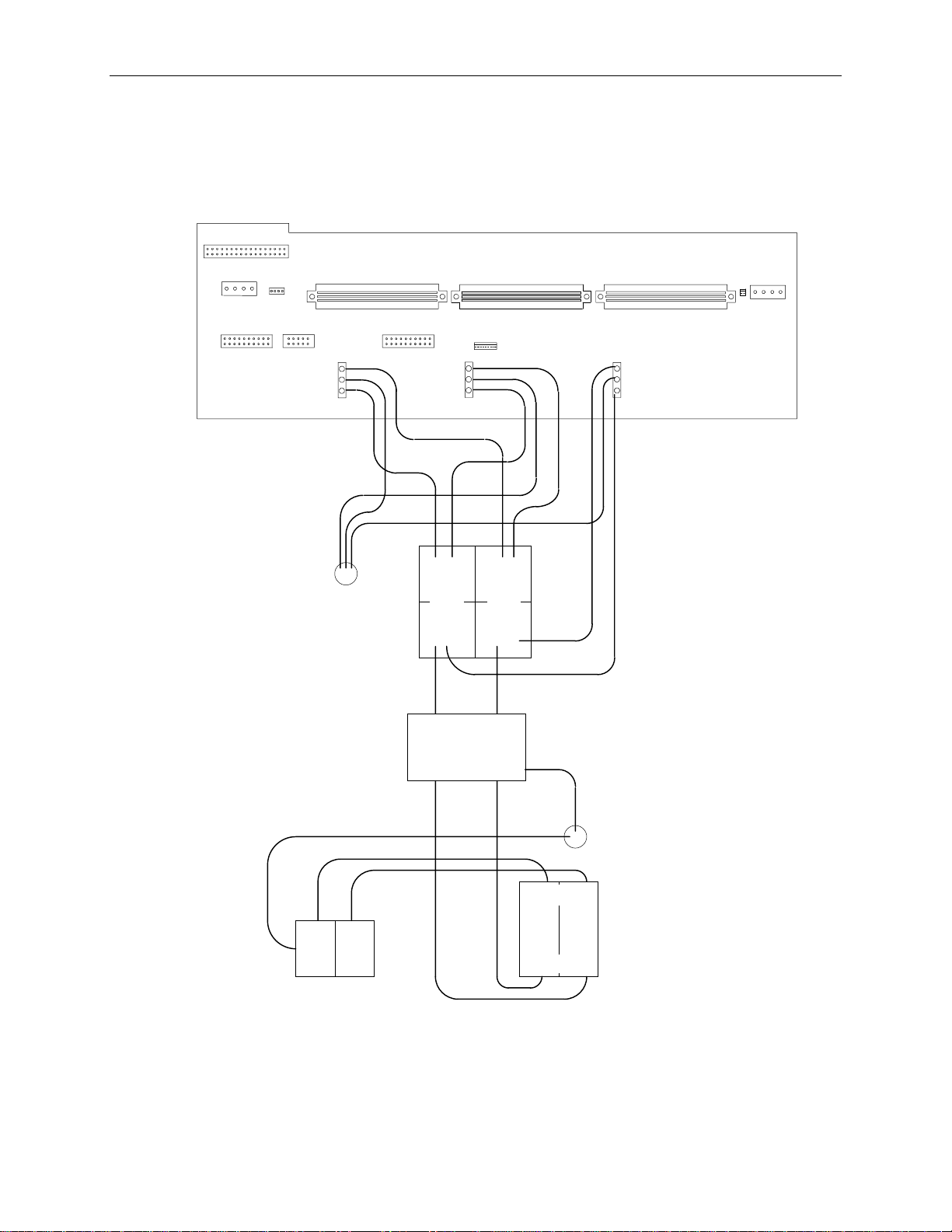
AC Input Wiring
The following diagram shows the AC input wiring, from AC receptacle (MCBL088) to the power
distribution board board.
83
Blue
Grn/Yell
Brown
Ground Lug
Terminal Block
CCON360 (Gray)
CCON362 (Blue)
Blue
Grn/Yell
Brown
BLUEGRAY
Brown Blue
CFIL070
AC LINE
FILTER
Brown Blue
Blue
Grn/Yell
Brown
MCBL133A Ground Wir e
Blue Brown
MCBL088
AC Receptacle
Ground Lug
TOP
CCRB060 Switch
BOTTOM
Page 94

84
Internal RAID Section (MESAN20)
Assembly Layout
Right/Top
Backplane
JP5
Bus Display
Jumper
J1
JP5
J3
J3
J8
JP2
J8
JP6
JP6
J4
Sensor
Board
Left/Bottom
Backplane
JP2
Page 95

Cable Routing and Pinouts
From MESAN20 Cable To
J1, Sensor Board MCBL096A Power distribution board, J11
J4, Sensor Board MCBL095A Power distribution board, J10
JP5, Back Plane (left) MCBL087A Power distribution board, J17
JP5, Back Plane (right) MCBL087A Power distribution board, J16
(InterServe)
J3, Back Plane (right)
(StudioZ RAX)
J3, Back Plane (right)
(StudioZ RAX)
J3, Back Plane (left)
J3 and J8, MCBL083A or MCBL108A, Internal RAID section SCSI
85
MCBL083A RAID Controller (CINF917) CH 2
(J8 right back plane, J3 left back plane,
J8 left back plane, CCON397B)
MCBL108A RAID Controller (CINF917) CH 0
(J8 right back plane, CCON397B)
MCBL108A RAID Controller (CINF917) CH 1
(J8 right back plane, CCON397B)
Signal
Ground 1-16 Shell OK (Ground) 50
Term Power 17 Term Power 51
Term Power 18 Term Power 52
No Connect 19 No Connect 53
Ground 20-34 Fault Clock (Ground) 54
SCSI Data Bit 12 35 Attention 55
SCSI Data Bit 13 36 Fault Data 56
SCSI Data Bit 14 37 Busy 57
SCSI Data Bit 15 38 Acknowledge 58
SCSI Data Parity 1 39 Reset 59
SCSI Data Bit 0 40 Message 60
SCSI Data Bit 1 41 Select 61
SCSI Data Bit 2 42 Carrier Detect 62
SCSI Data Bit 3 43 Request 63
SCSI Data Bit 4 44 I/O 64
SCSI Data Bit 5 45 SCSI Data Bit 8 65
SCSI Data Bit 6 46 SCSI Data Bit 9 66
SCSI Data Bit 7 47 SCSI Data Bit 10 67
SCSI Data Parity 0 48 SCSI Data Bit 11 68
SWAP (Ground) 49
Pin Signal Pin
Page 96

86
J4, MCBL095A, Internal RAID LCD
Signal Pin Signal Pin Signal
Pin
1 Ground 8 Data 1 15 No Connect
2 No Connect 9 Data 2 16 Menu
3 Ground 10 Data 3 17 Escape
4 DISPRS 11 Data 4 18 Down
5 DISPRW 12 Data 5 19 Enter
6 DISPENB 13 Data 6 20 Up
7 Data 0 14 Data 7
JP5, MCBL087A, Internal RAID section drives power
Pin
Signal Wire Color
1 +12V Yellow
2 Ground Black
3 Ground Black
4 VCC Red
Bus Display Jumper
The two backplane boards of MESAN20 contain a jumper header JP2. Note the difference between
InterServe 650, 660 and StudioZ RAX: For StudioZ RAX, the JP2 header on the top/left backplane
contains a jumper on pins 3 and 4. This ensures the system displays the appropriate dual-bus
information when the system boots. The InterServe systems do not contain a jumper on pins 3 and 4.
Service Notice
Early releases of the system included a cable (MCBL107A) that connected J12 on the power
distribution board to J3 on the RAID sensor board. If the power distribution board in the system has
J12 populated, then incorrectly attaching the cable could cause damage to the power distribution board
or the RAID sensor card. When replacing the internal RAID section assembly or power distribution
board, remove the cable MCBL107A from the system. This cable is not required for proper system
operation.
Page 97

Power Supplies (MPWS139)
The InterServe 650 and 660 servers and StudioZ RAX workstations use redundant 550 watt currentsharing power supplies. Each power supply has six outputs, is hot swappable, and is auto-ranging
between 90 - 132 VAC and 180 - 264 VAC. The input frequency range for each power supply is
47 - 63 Hz, single phase. The power supply has the following DC output specifications:
87
Nominal Output
Voltages
Continuous Load
(Maximum.)
Continuous Load
(Minimum.)
1, 3
1
1
Noise and Ripple
(PARD) (DC to
30 MHz)
Initial Setting
Tolerance
Regulation
Line/Load
3
2, 3
Overshoot
(Turn on/off)
DC Output Specification Notes:
1. The power supply meets or exceeds these specifications.
2. These outputs are measured differentially at the Elcon connector terminated with 0.1 µf ceramic
Output 1
4, 5
Output 2
4, 5
Output 3 6Output 4 5Output 5 Output 6 Unit
+3.3 +5.1 +5.0 +12.0 -12.0 -5.0 VDC
45 85 1 12 1 1 ADC
0.0 3.5 0.0 1.0 0.0 0.0 ADC
50 50 50 100 250 100 mVp-p
3% 3% 3% 5% 10% 10% Max
3% 3% 3% 5% 10% 10% Max
5% 5% 5% 10% 10% 10& Max
capacitor.
Max
3. The sum of the Initial Setting Tolerance and Line/Load Regulation does not exceed 3% for the
+3.3 V, +5.1 V, and +5.0 V (always on) outputs, 5% for the +12.0 V output, and 10% for the
negative output voltages.
4. Any combination of +3.3 V or +5.1 V do not exceed their maximum power or 450 watts of total
power.
5. Any combination of +3.3 V, +5.1 V, or +12 V do not exceed their maximum power or 550 watts of
total power.
6. This output is always on.
Operating characteristics of the power supplies include the following:
u
Over-Current Protection is provided on +3.3 VDC and +5.1 VDC outputs. The Over-Current
Protection disables the DC outputs (except the +5.0 V) and keeps them disabled until AC is
cycled.
u
Over-Voltage Protection is provided on +3.3 VDC and +5.1 VDC. The Over-Voltage Protection
disables the DC outputs (except the +5.0 V) when the output reaches 5.5 - 6.8 VDC for +5.1 V DC
or 3.7 - 4.4 VDC for +3.3 VDC. The DC outputs remain disabled until AC is cycled.
u
Once the +5.1 V output is turned on by the power supply, it reaches its nominal output (see the
table above) within 750 ms at all line and load conditions.
Page 98

88
u
The current is equally shared (within +10%) by the two power supplies at maximum load. If one
power supply fails, the remaining power supply takes over. +3.3 V, +5.1 V, +12 V, -5 V, and 12V power outputs have series-connected blocking diodes to prevent an output fault in one power
supply from pulling down the outputs of the other power supply.
u
If one of the power supplies fails, an LED in that power supply either goes out or changes from
green to amber, and the power on LED on the front of the base unit changes from green to amber.
Look at the back of the base unit to see which power supply failed.
u
If a power supply is not supplying all of its DC voltage output levels correctly, an audible alarm
sounds.
The pinout for the power supply connectors (which plug into J4, J5, J6 on the power distribution board)
is as follows.
Pin
Name Pin Name Pin Signal
1 AC Line 14 Ground 26 Ground
2 AC Ground 15 +3.3 V 27 Remote ON/OFF
3 AC Neutral 16 Current share +3.3 V 28 Ground
4 No connect 17 Current share +5.1 V 29 +12 V
5 No connect 18 Current share +12 V 30 +12 V
6 No connect 19 Current share return 31 +12 V
7 +3.3 V 20 AC OK
8 Ground 21 DC OK
1
2
32 +12 V
33 -12 V
9 +3.3 V 22 Ground 34 Ground
10 +3.3 V 23 -5 V 35 Ground
11 Ground 24 Ground 36 +5.1 V
12 Fan 1 Tach 25 +5.0 V - always on 37 +5.1 V
13 Fan 2 Tach
Pinout Notes:
1. The AC OK signal is a TTL-compatible signal. It monotonically (without wavering) transitions to
a high level to indicate that the AC input power is within 90 - 132 VAC or 180 - 264 VAC. The
signal provides the 3 mA sink/source current as well as any current required for the LEDs.
Provided that there is an AC input, this signal must be available to report whether or not the
outputs are functional. Overshoot should be kept to less than 1 V above a maximum steady-state
high-level output of 5 V. Undershoot should be kept to less than -1 V below a minimum steadystate low-level output of 0 V.
2. The DC OK signal is a TTL-compatible signal, and its purpose is to initiate an orderly start-up
procedure under normal operating conditions. During power up, this signal should remain low
(less than 0.8 V) for at least 100 ms after all of the +5.1 V, +3.3 V, and +12 V outputs have
reached their minimum sense levels of 4.75 V, 3.14 V and 11.4 V, respectively. The signal then
monotonically (without wavering) transitions to a high level (greater than 2.4 V) to indicate that
the power source is stable. The signal provides the 3 mA sink/source current as well as any current
required for the LEDs. Overshoot should be kept to less than 1 V above a maximum steady-state
high-level output of 5 V. Undershoot should be kept to less than -1 V below a minimum steadystate low-level output of 0 V.
Page 99

Monitors
15-inch, 17-inch, and 21-inch multiple sync monitors are supported. Refer to monitor documentation
for technical information about monitor hardware. Resolutions and refresh rates for Intergraph
monitors are:
u
Intergraph 15-inch (MDSP140) - up to 1024x768 and refresh rates up to 75 MHz.
u
Intergraph 17SD86 (MDSP141) - up to 1600x1200 and refresh rates up to 65 Hz. The maximum
supported horizontal refresh rate is 86 KHz.
u
Intergraph 21SD82 (MDSP131) - up to 1600x1200 and refresh rates up to 65 Hz. The maximum
supported horizontal refresh rate is 82 KHz.
u
Intergraph 21SD95 220 MHz (MDSP142) - up to 1600x1200 and refresh rates up to 75 Hz. The
maximum supported horizontal refresh rate is 95 KHz.
u
Intergraph 21SD107 220 MHz (MDSP139) - up to 1600x1200 and refresh rate of 80 Hz. The
maximum supported horizontal refresh rate is 107 KHz.
InterServe 650, 660 systems support remote monitors using the concentrator (FINF924 or FINF925).
The concentrator allows 7 feet, 25 feet, or 50 feet cable lengths. One 25-foot cable set is standard for
each concentrator.
89
StudioZ RAX supports remote monitors via the PC Extender (CINF033). The PC extender allows the
monitor (and mouse and keyboard) to be used over 100 feet from the system. One 100-foot UTP
category five cable set is standard for each workstation. The cables can be extended to 300 feet using
standard UTP category five cables.
NOTE The stereo mode of the RealiZm video display driver cannot be used when the monitor is connected to
the PC Extender. The monitor display appears pink and distorted.
Page 100

90
Intruder Alert
The 19-inch rack is wired to report intruder alerts to InterServe 650 and 660 systems in the rack or in
adjacent racks. The following diagram illustrates the wiring scheme:
1
5
Front of Sys tem Rack
3
1. Front Door Switch - This switch is closed
when the door is closed. When opened,
the intruder alert activtes, if configured to
do so in the LCD menu. Refer to Chapter
3 of the
2. Expansion Plugs - These plugs are loop
access points, which provide connection to
expansion racks. Terminators (3) are
installed to close the circuit if expansion
racks are not connected.
3. Terminators - These items close the
circuit loop, and are removed to
accomodate intruder alert cabling for
expansion racks.
4. Rear Door Switch- This switch is closed
when the door is closed. When opened,
the intruder alert activtes, if configured to
do so in the LCD menu. Refer to Chapter
3 of the
5. Connector - The connector at the end of
the intruder alert cable attaches to the
base unit, and detects an open circuit.
System Setup
System Setup
.
.
2
4
 Loading...