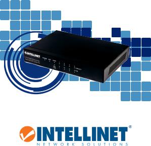
Intellinet 561174 Manual

5-Port Gigabit Ethernet PoE+ Switch with SFP Combo Port
Quick Instruction Guide
Models 561174
intellinetnetwork.com
Important: Read before use.• Importante: Leer antes de usar.
INT-561174_QiG-0317_REV-5.02

5-Port Gigabit PoE+ Switch with SFP Combo Port |
English |
|
|
This guide presents the basic steps to set up and operate this device. For detailed instructions and specifications, refer to the user manual enclosed with this product or at intellinetnetwork.com.
 Placement
Prior to use, place/position the switch:
•On a level surface that can support the weight of the switch (and any other items that need to be considered);
•With a minimum of 25 mm (approx. 1”) of clearance on the top and sides for adequate ventilation;
•Away from sources of electrical noise: radios, transmitters, broadband amplifiers, etc.;
•Where it cannot be affected by excessive moisture.
 Connections
All ports on the switch support Auto-MDI/MDI-X functionality, so you can use straight or crossover UTP/STP cables to connect the RJ45 ports to PCs, routers, hubs, other switches, etc.
LED |
Status |
Operation |
PWR |
On |
PowerOn |
|
Off |
Check connection; turn power on |
1 - 5 |
On |
Valid port connection |
|
Blinking |
Datatransmitted/received |
|
Off |
No link established |
PoE |
On |
Port is linked to PSE/PoE device |
|
Off |
No PSE/PoE device is linked |
PoE Limit |
On |
PowerdrawofconnectedPoEdevicesexceedsavailablePoEbudget |
Uplink |
On |
Valid port connection on port 5 |
|
Blinking |
Valid port connection; data transmitted/received |
|
Off |
No link established |
SFP |
On |
SFP module inserted, link established |
•The LED indicators make monitoring and troubleshooting easier. If a status LED doesn’t indicate a link or activity, check the corresponding device for proper setup and operation.
•Use the included power adapter (54VDC) to connect the receptacle on the back of the switch to a power outlet, and confirm that the Power LED lights.
2 English

Deutsch |
5-Port Gigabit Ethernet PoE+ Switch mit |
|
SFP Combo-Port |
||
|
Diese Kurzanleitung zeigt die grundlegenden Schritte zur Einrichtung und Inbetriebnahme dieses Geräts. Für genauere Anweisungen nutzen Sie bitte das beiliegende Handbuch oder auf intellinetnetwork.com.
 Nutzungsumgebung
Er wird empfohlen, den Switch vor der Nutzung folgendermaßen aufzustellen:
•Auf ebenem Untergrund, der das Gewicht des Switches (undevtl.andererGegenstände)trägt;
•Mit mindestens 25 mm Abstand zu allen Seiten für angemessenen Luftdurchsatz;
•Fern von anderen Übertragungsgeräten wie Radios, Breitbandverstärker, etc.;
•Nicht in feuchten Umgebungen.
 Anschlüsse
Alle Ports unterstützen Auto-MDIX Funktionalität, daher können Sie ein Crossoveroder Nicht-Crossover UTP-/STP-Kabel verwenden, um die RJ45-Ports mit PCs, Routern, Hubs, anderen Switchen etc. zu verbinden.
LED |
Status |
Bedeutung |
|
PWR |
An |
Gerät wird mit Strom versorgt |
|
|
Aus |
Stromanschluss prüfen/Gerät einschalten |
|
1 - 5 |
An |
Verbindung ist hergestellt |
|
|
Blinkend |
Datenübertragung |
|
|
Aus |
Verbindung ist nicht hergestellt |
|
PoE |
An |
Port ist mit einem PSE-/PoE-Gerät verbunden |
|
|
Aus |
Es ist kein PSE-/PoE-Gerät verbunden |
|
PoE Limit |
An |
Stromaufnahme der verbundenen PoE-Geräte übersteigt verfügbares |
|
PoE-Budget |
|||
|
|
||
Uplink |
An |
Gültige Portverbindung an Port 5 |
|
|
Blinkend |
GültigePortverbindung;Datengesendet/empfangen |
|
|
Aus |
KeineVerbindunghergestellt |
|
SFP |
On |
SFP-Moduleingesteckt,Verbindunghergestellt |
•Die LEDs zeigen Funktionen an und helfen bei Problemdiagnosen. Wenn eine LED keineVerbindung/Aktivitätanzeigt,überprüfenSiedasverbundeneGerät.
•Verwenden Sie das beiliegende Netzteil (54VDC), um die Strombuchse auf der Rückseite des Switches mit einer Steckdose zu verbinden und prüfen Sie, dass die Power-LED leuchtet.
Deutsch 3

Switch de 5 puertos Gigabit Ethernet PoE+ con |
Español |
|
puerto combo SFP |
||
|
Esta guía presenta los pasos básicos para instalar y operar este dispositivo. Para obtener instrucciones detalladas y más especificaciones, consulte el manual de usuario incluido o en intellinetnetwork.com.
Colocación
Antes de utilizarlo, se recomienda que el switch sea colocado/fijado:
•Sobre una superficie plana que pueda soportar el peso del switch (y cualquier otro artículo que deba ser considerado);
•Con un mínimo de 25 mm (1” aprox.) de espacio libre en la parte superior y en los lados para una ventilación adecuada;
•Apartado de fuentes de ruido eléctrico: radios, transmisores, amplificadores, etc.;
•Donde no sea afectado por la humedad excesiva.
Conexiónes
Todos los puertos del switch soportan Auto-MDI/MDI-X, puede utilizarse cable directo o cruzado UTP/STP para conectar los puertos RJ45 a la PC, router, hub, otros switches, etc.
LED |
Estado |
Operación |
PWR |
Encendido |
Encendido |
|
Apagado |
Compruebe la conexión, p/encender |
1 - 5 |
Encendido |
Válida el puerto de conexión |
|
Parpadeo |
Datos enviados/recibidos |
|
Apagado |
No hay conexión |
PoE |
Encendido |
El puerto está conectado al dispositivo PSE/PoE |
|
Apagado |
No conecta ningún dispositivo PSE/PoE |
Limite PoE |
Encendido |
ElconsumodeenergíadelosdispositivosPoEconectadosexcedeel |
|
|
presupuesto de PoE disponible |
Enlace |
Encendido |
Conexiónválidapuerto5 |
ascendente |
||
|
Linkeando |
Conexióndepuertoválida;Datostransmitidos/recibidos |
|
Apagado |
Enlace no establecido |
SFP |
Encendido |
MóduloSFPinsertado,enlaceestablecido |
•Los LED indicadores permiten el monitoreo y detección de problemáticas de manera sencilla. Si un LED no indica conectividad o actividad, verifique que la configuración y la operación del equipo sean adecuadas.
•Utilice el adaptador de corriente externo incluido (54 VDC) para conectar el receptáculo en la parte trasera del switch con una toma de corriente, y confirme que el LED de encendido se ilumina.
4 Español
 Loading...