

Page 1
Quadrax 1.1 Manual
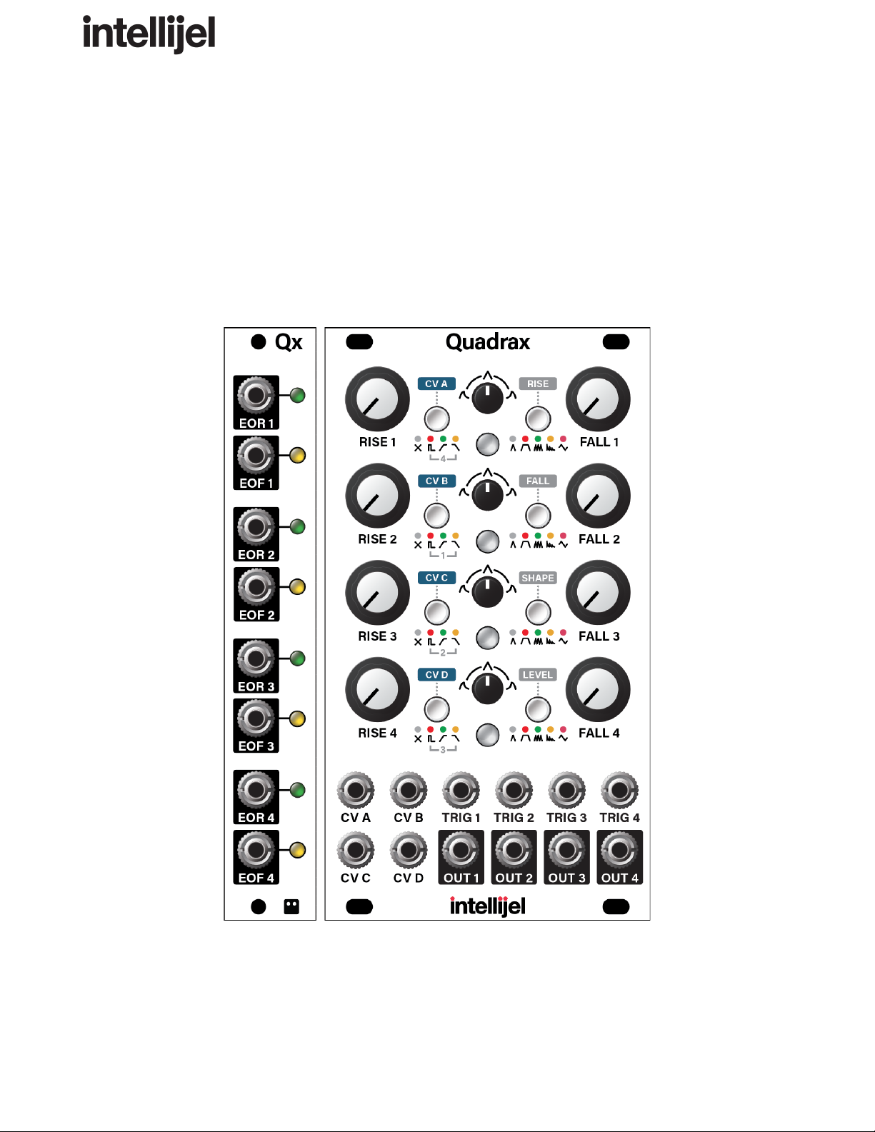
Quadrax
(Including Optional Qx Expander)
4-Channel CV-Controllable Function Generator
With Cycling, Pulse Burst Generation and Morphing LFO
Firmware Version: 1.1.3
Manual Revision: 2020.04.02
Page 2

Quadrax 1.1 Manual
Table of Contents
Compliance 3
Installation 4
Installing Your Module 5
Connecting the Optional Qx Expander Module 6
Overview 7
Quadrax Front Panel 9
Controls 9
Inputs and Outputs 14
Channel Mode Options 16
AD Mode 16
AHR Mode 17
CYCLE Mode 18
BURST Mode 18
LFO Mode 19
Channel Link Options 20
No Link 20
Trigger Link 21
End Of Rise Link 21
End of Fall Link 22
Multiple Triggers 22
Burst Mode - In Detail 23
LFO Mode - In Detail 26
LFO Mode (STANDARD) 26
Multiple Beat Synchronized LFOs 28
STANDARD LFO Waveshapes and Morphing 29
LFO Mode (ALTERNATE) 30
Page 1
Page 3

Quadrax 1.1 Manual
Making CV Assignments 32
Enter/Exit CV Assignment Mode 32
Programming the CV Matrix 33
Clearing CV Assignments 36
Using the Optional Qx Module 37
EOR/EOF for AD Mode 37
EOR/EOF for AHR Mode 38
EOR/EOF for CYCLE Mode 38
EOR/EOF for BURST Mode 39
EOR/EOF for LFO Mode 40
System Mode 41
System Mode Options 41
10V/5V Option 41
Burst Retriggering Option 41
Dithering Option 42
Reset to Default 42
Firmware Version Display 43
Firmware Change Log 44
Technical Specifications 47
Page 2
Page 4
Quadrax 1.1 Manual
Compliance
This device complies with Part 15 of the FCC Rules. Operation is subject to the
following two conditions: (1) this device may not cause harmful interference, and
(2) this device must accept any interference received, including interference that
may cause undesired operation.
Changes or modifications not expressly approved by Intellijel Designs, Inc. could
void the user’s authority to operate the equipment.
Any digital equipment has been tested and found to comply with the limits for a
Class A digital device, pursuant to part 15 of the FCC Rules. These limits are
designed to provide reasonable protection against harmful interference when the
equipment is operated in a commercial environment. This equipment generates,
uses, and can radiate radio frequency energy and, if not installed and used in
accordance with the instruction manual, may cause harmful interference to radio
communications.
This device meets the requirements of the following standards and directives:
EMC: 2014/30/EU
EN55032:2015 ; EN55103-2:2009 (EN55024) ; EN61000-3-2 ; EN61000-3-3
Low Voltage: 2014/35/EU
EN 60065:2002+A1:2006+A11:2008+A2:2010+A12:2011
RoHS2: 2011/65/EU
WEEE: 2012/19/EU
Page 3
Page 5

Quadrax 1.1 Manual
Installation
Intellijel Eurorack modules are designed to be used with a Eurorack-compatible case and power
supply. We recommend you use Intellijel cases and power supplies.
Before installing a new module in your case, you must ensure your power supply has a free power
header and sufficient available capacity to power the module:
● Sum up the specified +12V current draw for all modules, including the new one. Do the same for
the -12 V and +5V current draw. The current draw will be specified in the manufacturer's technical
specifications for each module.
● Compare each of the sums to specifications for your case’s power supply.
● Only proceed with installation if none of the values exceeds the power supply’s specifications.
Otherwise you must remove modules to free up capacity or upgrade your power supply.
You will also need to ensure your case has enough free space (hp) to fit the new module. To prevent
screws or other debris from falling into the case and shorting any electrical contacts, not leave gaps
between adjacent modules, and cover all unused areas with blank panels. Similarly, do not use open
frames or any other enclosure that exposes the backside of any module or the power distribution
board.
You can use a tool like ModularGrid to assist in your planning. Failure to adequately power your
modules may result in damage to your modules or power supply. If you are unsure, please contact us
before proceeding.
Page 4
Page 6

Quadrax 1.1 Manual
Installing Your Module
When installing or removing a module from your
case always turn off the power to the case and
disconnect the power cable. Failure to do so may
result in serious injury or equipment damage.
Ensure the 10-pin connector on the power cable is
connected correctly to the module before
proceeding. The red stripe on the cable must line
up with the -12V pins on the module’s power
connector. Different modules use different ways to
indicate the -12V pins. Some may be labelled with
“-12V;” a white stripe next to the -12V pins; the
words “red stripe;” or some combination of these.
Additionally, some modules may have shrouded
headers, thus preventing backward connections.
Most modules will come with the cable already connected but it is good to double check the
orientation. Be aware that some modules may have headers that serve other purposes so ensure the
power cable is connected to the right one.
The other end of the cable, with a 16-pin connector,
connects to the power bus board of your Eurorack
case. Ensure the red stripe on the cable lines up
with the -12V pins on the bus board. On Intellijel
power supplies the pins are labelled with the label
“-12V” and a thick white stripe:
If you are using another manufacturer’s power
supply, check their documentation for instructions.
Page 5
Page 7
Quadrax 1.1 Manual
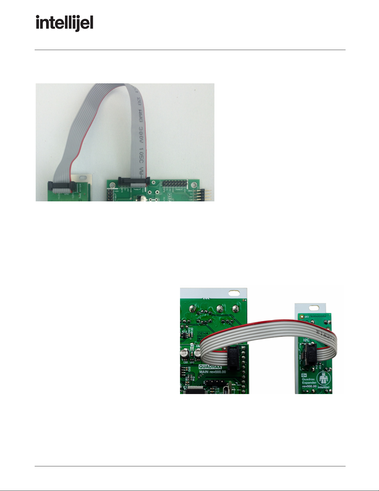
Once connected, the cabling between the module and power supply should resemble the picture
below:
Before reconnecting power and turning
on your modular system, double check
that the ribbon cable is fully seated on
both ends and that all the pins are
correctly aligned. If the pins are
misaligned in any direction or the ribbon
is backwards you can cause damage to
your module, power supply, or other
modules.
After you have confirmed all the
connections, you can reconnect the
power cable and turn on your modular
system. You should immediately check
that all your modules have powered on and are functioning correctly. If you notice any anomalies, turn
your system off right away and check your cabling again for mistakes.
Connecting the Optional Qx Expander Module
Connect the power cable between the 10-pin Qx power connector and one 16-pin power socket on
your eurorack system’s powered bus board as described above.
Using the I2C cable supplied with your Qx
module, connect one end to the 6-pin I2C
connector on the Qx and the other end to
either of the two I2C ports on your Quadrax
module (it doesn’t matter which of Quadrax’s
two I2C ports you use). Be sure to align the
red stripe with the white line on the Qx circuit
board.
IMPORTANT! : Always power down the
modules before connecting or disconnecting
an I2C cable.
Page 6
Page 8

Quadrax 1.1 Manual
Overview
The Intellijel Quadrax consists of four independent, CV-controllable channels, each of which can be
configured to perform any one of the following functions:
● an AD (Attack, Decay) envelope
● an AHR (Attack, Hold, Release) envelope
● a cycling envelope (resulting in a unipolar LFO)
● a pulse burst generator
● a morphing, bipolar LFO (plus a chaotic Low Frequency Vacillator)
The envelopes all feature a continuously variable response curve, ranging from logarithmic through
linear to exponential, and each stage can be as snappy as 0.3 ms to as lengthy as 20 seconds.
When set to Burst mode, the channel generates a rising or falling burst of pulses, with full control over
the length of the pulse burst, and the rate and shape of the bursts within it, along with whether the
bursts increase or decrease in amplitude over the burst length.
AD, AHR, Cycling and Burst modes have a user-selectable maximum output level of either 5V or 10V.
LFO mode offers control over the frequency and waveshape, while providing a unique morphing
feature that creates numerous variations of the selected waveshape. LFOs can be either free-running
or beat-synchronized using the channel’s TRIG input.
Each of the five modes (AD, AHR, Cycling, Burst and LFO) provide both standard and alternate
modes of operation, giving you even more nuanced control. Specifically, the alternate functionality for
AD, AHR and CYCLE modes changes the response curves of the envelope — enabling RISE to have
a logarithmic shape while FALL’s shape is exponential, and vice-versa. BURST Mode’s alternate
function replaces the Square/Sine morphing pulse shape with a Tilting Sawtooth shape. The alternate
LFO operation enables a chaotic voltage source (which we call a “Low Frequency Vacillator (LFV)”,
and the knobs control the rate of vacillations, along with the per-cycle variance and the amount it’s
slewed.
Channels can be chained together to create complex multi-stage envelopes, with each channel
triggered by the previous channel’s trigger input, end-of-rise, or end-of-fall. This enables multiple
function generators to fire simultaneously, or it enables the creation of complex multi-stage envelopes
by allowing the linked function to fire either at the end of the previous function’s rise time, or at the end
of its fall time.
Page 7
Page 9

Quadrax 1.1 Manual
Four freely-assignable, step-attenuverted CV inputs are capable of modulating any or all of the
various parameters across all four channels using the built-in CV matrix, with built-in attenuversion for
each assignment.
1 v/oct CV inputs enable you to use LFO and Burst modes as oscillators.
Quadrax remembers its current state (Mode and CV assignments, channel links, etc) and retains that
state even if power is removed, meaning Quadrax will always turn on in exactly the same state as you
last left it.
Use the optional Qx module to add individual outputs for each channel’s End-of-Rise and End-of-Fall
triggers.
Page 8
Page 10
Quadrax 1.1 Manual
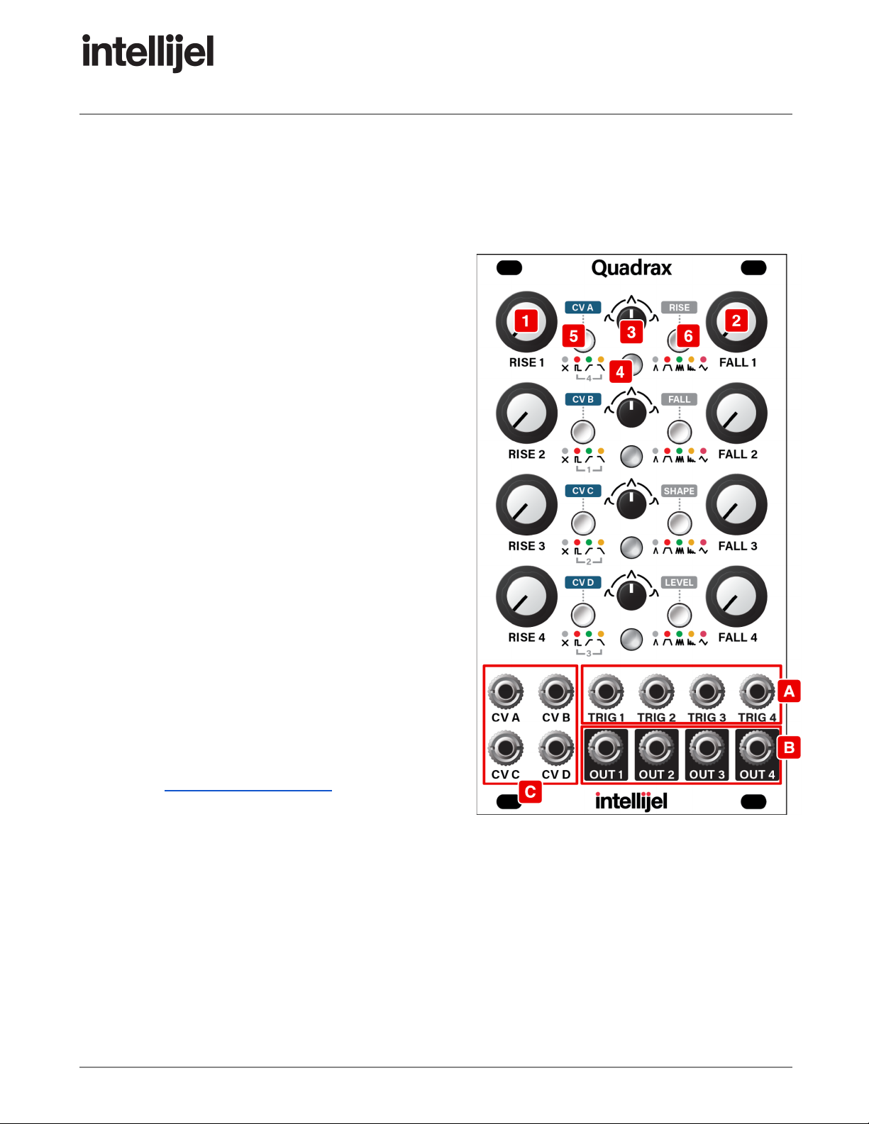
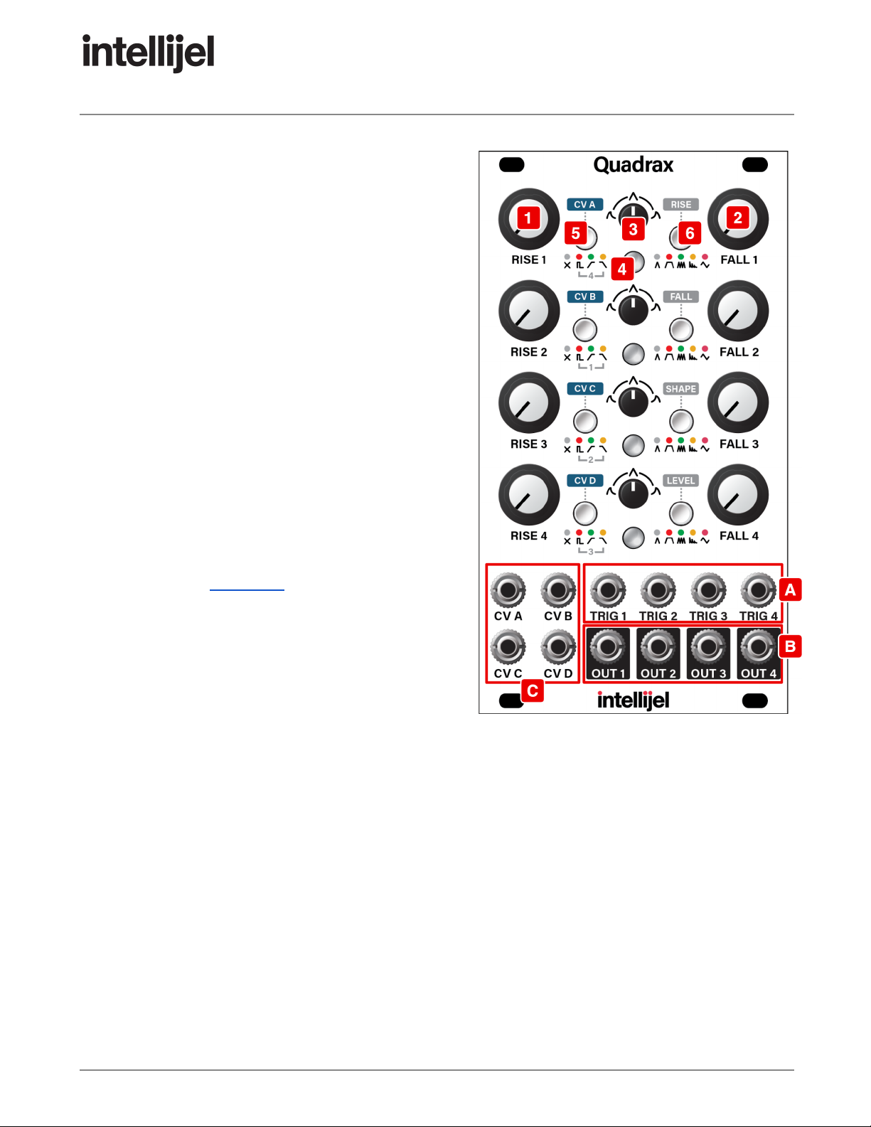
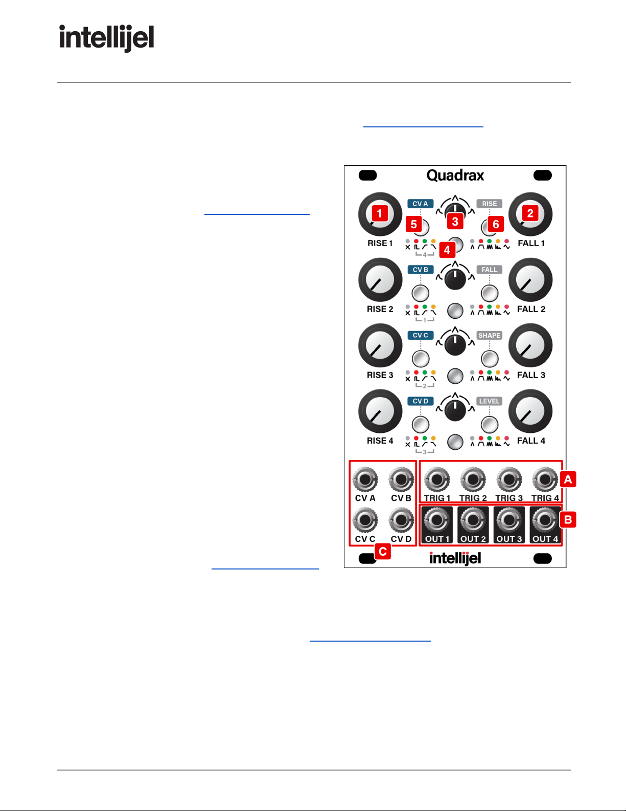
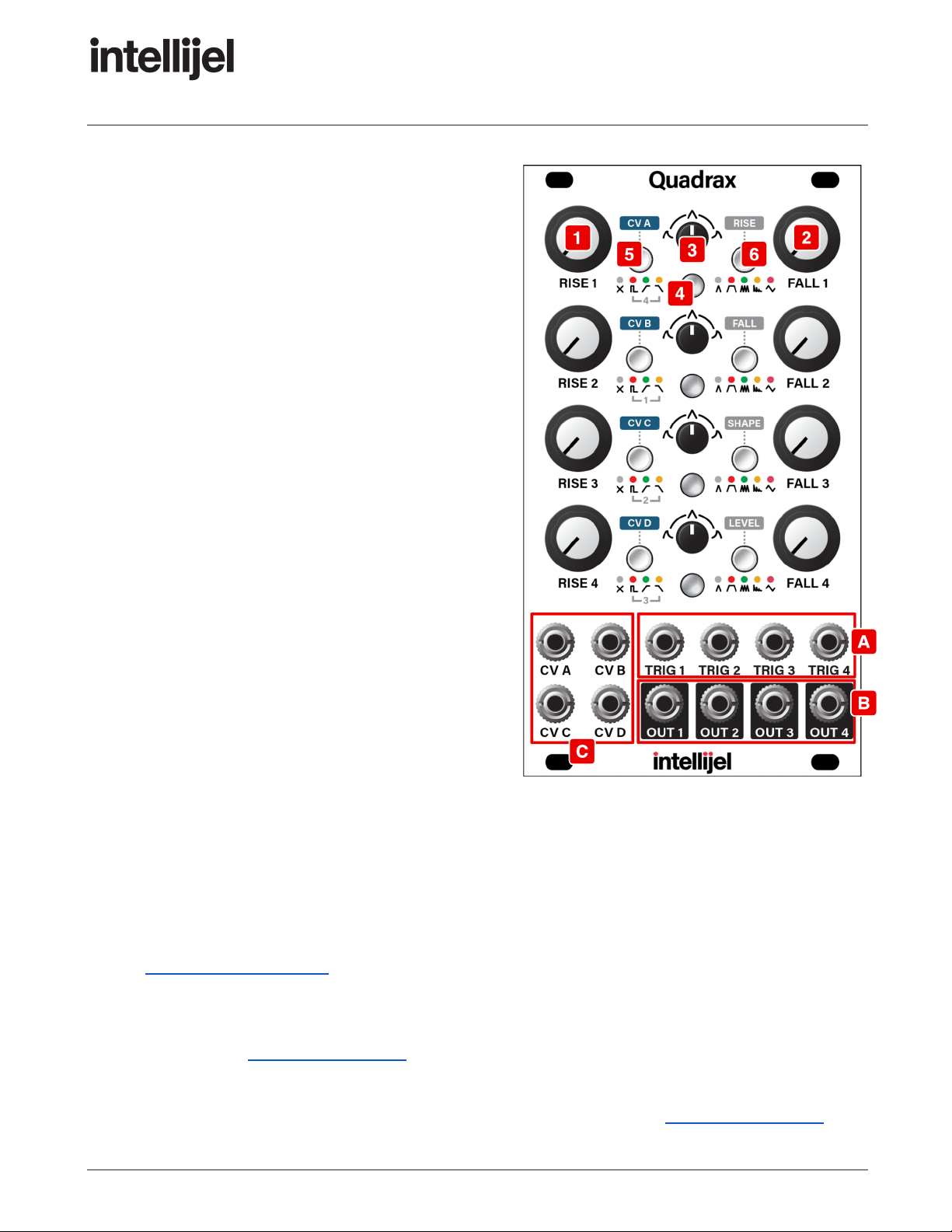
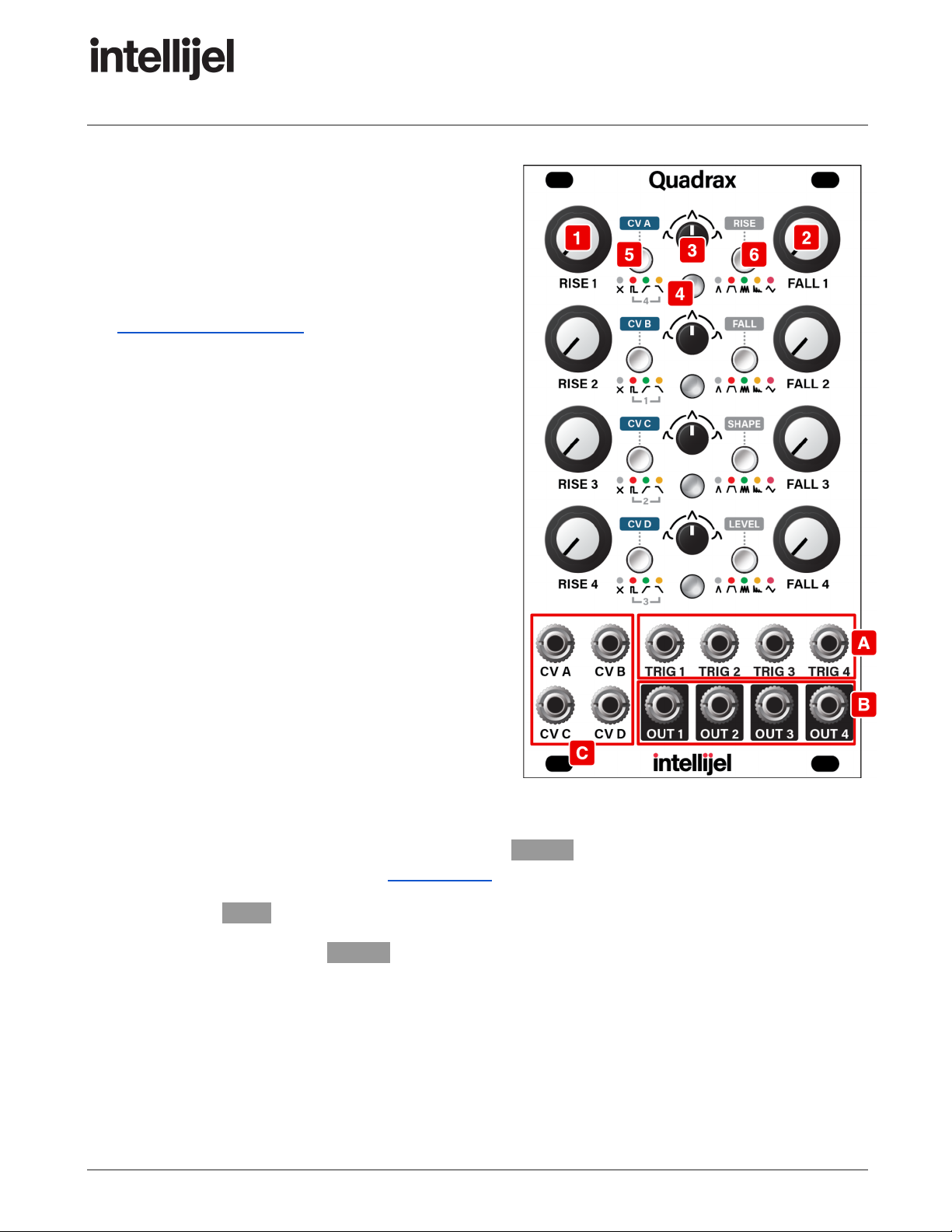
Quadrax Front Panel
Controls
1. RISE (x4) - Each channel has its own RISE knob,
whose function depends on the channel’s mode
assignment, as selected by the
MODE/DESTINATION button [6] .
● AD , AHR and CYCLE modes: This knob
controls the rise time (attack) of the function
(rising from zero to the maximum level). Slower
times will create a fade-in effect while faster
times are used for snappy percussive sounds.
When fully counterclockwise, rise time is about
0.3 ms, slowing to about 50 ms at the ‘noon’
position. Rotating past noon results in
increasingly lethargic rise times, up to about
20 seconds when fully clockwise.
● BURST Mode : The RISE knobs sets the rate at
which pulses are generated within the burst
envelope.
When the RISE knob is fully counter-clockwise,
Quadrax generates pulses at a rate of 0.05 Hz,
and when fully counterclockwise at about
3.33 kHz.
See BURST Mode - In Detail later in this
manual for more information.
Page 9
Page 11
Quadrax 1.1 Manual
● LFO Mode : The RISE knob functions as a
RATE knob for the LFO.
With nothing patched into the TRIG input, the
LFO is free-running and the knob sets the LFO
rate from 0.05 Hz (20 sec) when fully
counterclockwise to around 3.33 kHz (0.3 ms)
when fully clockwise. Using CV extends the
range even further.
If you patch a clock into the TRIG input, the
LFO will synchronize to the clock, and the RISE
knob changes the multiplication/division of the
incoming clock. At the ‘noon’ position, the rate
equals the incoming clock. Rotating the knob
counterclockwise divides the clock, achieving a
rate 1/64 of the clock rate when fully
counterclockwise. Rotating the knob clockwise
multiplies the clock rate, achieving a rate 64
times faster than the incoming clock when fully
clockwise. For more information about LFO
Mode, see LFO Mode , later.
2. FALL (x4) - Each channel has its own FALL knob,
whose function depends on the channel’s mode
assignment, as selected by the
MODE/DESTINATION [6] button.
● AD , AHR and CYCLE modes: Sets the amount
of time it takes for the function to fall from its maximum value back to zero. In AHR mode this
will act as the release time. In Cycle mode the total time of RISE plus FALL sets the frequency
of the cycle.
When fully counterclockwise, fall time is about 0.3 ms, slowing to about 50 ms at the ‘noon’
position. Rotating past noon results in increasingly lethargic fall times, up to about 20 sec
when fully clockwise.
● BURST Mode: The FALL knobs sets the overall length of the pulse burst envelope.
Rotating the knob increases the length of the pulse burst from about 0.3 ms when fully
counterclockwise to around 20 seconds when fully clockwise. Using CV extends the range
even further.
● LFO Mode: The FALL knob becomes a MORPH knob (for a STANDARD LFO), and is used to
create numerous interesting and morphable variations on the basic waveform set by the
Page 10
Page 12
Quadrax 1.1 Manual
SHAPE [3] knob. For the ALTERNATE LFO (a Low Frequency Vacillator), the FALL knob
becomes a VARIANCE knob, setting the maximum amount of variance for each vacillation.
These are detailed in the LFO Waveshapes and Morphing section, later in this manual).
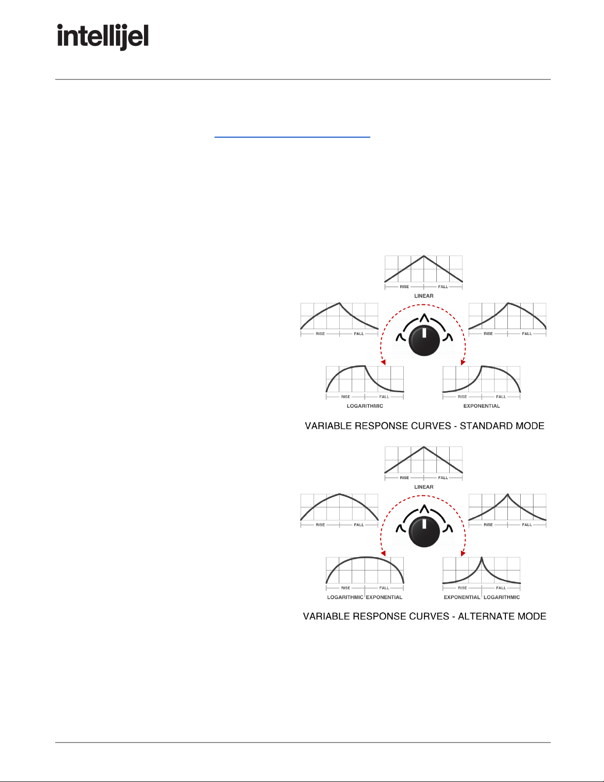
3. SHAPE (x4) - Each channel has its own SHAPE knob, whose function depends on the channel’s
mode assignment, as selected by the MODE/DESTINATION button [6] .
● In AD , AHR and CYCLE modes: This knob changes the shape of the RISE and FALL curves.
At the ‘noon’ position, the curves are linear, which is traditionally the shape used to control
exponential VCAs.
Other shapes depend on whether the
AD, AHR and CYCLE modes are set to
STANDARD or ALTERNATE operation
(toggled by long-pressing (>1 sec) the
MODE/DESTINATION [6] button).
In STANDARD operation : Rotating the
knob clockwise from center results in
an increasingly exponential shape. This
is the curve found on many classic
envelope generators, and is
traditionally used to control linear
VCAs. Exponential shapes tend to
have more of a plucked character.
Rotating the knob counterclockwise
from center results in an increasingly
logarithmic shape.
IN ALTERNATE operation: Rotating
the knob clockwise from center results
in an increasingly spikey shape, since
an exponential curve is applied to the
attack stage, and a logarithmic curve is
applied to the decay/release stage.
Rotating the knob counterclockwise
from center results in an gradual, bell-like shape, since a logarithmic curve is applied to the
attack stage, and an exponential curve is applied to the decay/release stage.
Page 11
Page 13
Quadrax 1.1 Manual
● In BURST Mode : The knob shapes the overall burst envelope plus the waveform of each
pulse within that envelope. For more information, see BURST Mode - In Detail , later in this
manual.
● In LFO Mode : The knob controls the LFO
shape, which is further defined by the FALL [2]
knob. LFO Mode’s interaction of these two
knobs is discussed in LFO Mode - In Detail ,
later in this manual.
4. LED - The brighter this LED (x4), the higher the
corresponding function generator’s amplitude. If the
LED is green , then the function is generating a
positive voltage. A red LED indicates a negative
voltage.
5. LINK/CV button - This button (x4) has two
functions, LINK and CV ASSIGN.
● LINK : The button’s primary function (as
indicated by the graphics beneath) is to
determine whether or not the prior channel
triggers this channel and, if so, how.
Specifically, the LINK button on Channel 2
determines if/how it’s triggered by Channel 1;
Channel 3’s button determines if/how it's
triggered by Channel 2; and Channel 4’s button
determines if/how it’s triggered by Channel 3.
Channel 1’s button determines if/how it’s
triggered by Channel 4. Push a channel’s LINK
button repeatedly to cycle through the various
triggering options. See Channel Link Options
for more information.
● CV ASSIGN : The button’s secondary function (as indicated by the label above it) is to assign
the four CV inputs to one or more destinations for each channel. Long-press the LINK/CV
button to enter CV Assignment mode. See Making CV Assignments for more information.
Page 12
Page 14
Quadrax 1.1 Manual
6. MODE/DESTINATION button - This button (x4) has
several functions: In normal operation, it selects the
channel’s MODE, while in CV Assignment mode, it
sets the DESTINATION (and attenuversion) of the
CV input. Additionally, long-pressing the button
toggles the current mode between its STANDARD
functionality and its ALTERNATE functionality.
When used as a MODE button, it sets each
channel to one of five modes. Push it repeatedly to
cycle through the various mode options, which are:
● AD : Attack/Decay envelope, where RISE
controls the envelope’s attack time and FALL
controls the decay time. AD envelopes
complete their entire cycle upon receiving a
trigger at the corresponding TRIG input. AD
envelopes ignore the gate time of the incoming
signal.
● AHR : Attack/Hold/Release envelope, where
RISE controls the envelope’s attack time and
FALL controls its release time. The attack
portion of the envelope is triggered by the rising
edge of a gate signal sent to the corresponding
TRIG input. The envelope holds (sustains) its
maximum value for as long as the gate signal is
high, then triggers the release stage when the
gate signal goes low.
● CYCLE : Cycle mode behaves like a unipolar LFO, with the RISE and FALL times determining
the rate and shape of the LFO.
● Burst : Burst mode generates a series of pulses that repeat at a variable rate (set the the RISE
knob) within a length of time (set by the FALL knob), whose pulse shapes and overall
amplitude curve are defined with the SHAPE knob. This mode is discussed thoroughly in
BURST Mode - In Detail , later in this manual.
● LFO : LFO mode turns a channel into a bipolar, beat-syncable LFO with multiple basic
waveshapes and some advanced waveshape morphing capabilities. This mode is discussed
thoroughly in LFO Mode - In Detail , later in this manual.
Once in a MODE, long-press (>1 sec) the MODE/DESTINATION button to toggle between
STANDARD operation and ALTERNATE operation, as described later in LFO Mode - In Detail .
Page 13
Page 15
Quadrax 1.1 Manual
In CV Assignment mode, this button assigns
destinations to CV inputs, and controls the amount
of attenuversion applied. The brighter the button,
the more a CV input affects a destination, with
green indicating positive modulation and red
indicating negative modulation. The operation of
the DESTINATION button is described fully in
Making CV Assignments .
Inputs and Outputs
A. TRIG Inputs (x4) - Patch a trigger or gate signal
here to launch the function generator. There are
four TRIG inputs — one for each of the four
function generators.
In LFO mode, the TRIG input functions as a clock
input, and the RISE (RATE) knob functions as a
clock divider/multiplier, allowing beat-synchronized
LFOs. Because the TRIG inputs have jack
detection, you can have free-running LFOs by
simply leaving the TRIG input disconnected.
B. OUTS (x4) - Outputs for each of the four channel
function generators.
Channels assigned to AD , AHR , CYCLE or BURST
modes generate a unipolar voltage, which you can
set to either 5V or 10V (with 10V being the factory default). To change this setting:
1. Hold down Channel 4’s MODE/DESTINATION ( LEVEL ) button while you power on the
module. This puts Quadrax into System Mode .
2. Press the CV A button to toggle max voltage level between 10V ( blue ) and 5V ( green ).
3. Press the flashing red ( LEVEL ) button to save your selection and exit System Mode.
Channels assigned to LFO mode generate a bipolar signal (-5V to +5V).
C. CV Inputs (x4) - Patch control voltages into each jack to modulate one or more user-definable
parameters for any or all of the four channels. Each CV input can control multiple destinations,
and with varying amounts of attenuversion for each.
Page 14
Page 16

Quadrax 1.1 Manual
CV inputs track 1 v/oct, so (for STANDARD LFO
and BURST modes), it’s possible to use Quadrax
as an oscillator by sending pitch CV to a CV input,
and using it to control the RISE function).
For more information about CV inputs and how to
make assignments, see Making CV Assignments ,
later in this manual.
NOTE: Although the range of CV modulation is
±5V, the CV inputs accept voltages up to ±10V. Any
voltages above or below 5V are simply clipped at
±5V. Use Quadrax’s internal attenuverters (as
described in Programming the CV Matrix ) to dial
down the input voltages.
Page 15
Page 17

Quadrax 1.1 Manual
Channel Mode Options
Each of Quadrax’s four channels can be assigned to operate in one of five modes:
Pushing the MODE button repeatedly cycles through the various mode options.
AD Mode
When the MODE [6] button is unlit, the channel is
a classic, 2-stage Attack/Decay envelope, where
RISE controls the envelope’s attack time and
FALL controls the decay time. AD envelopes
complete their entire cycle upon receiving a
trigger at the corresponding TRIG input. AD
envelopes ignore the gate time of the incoming
signal.
In STANDARD operation, the RISE and FALL
curves are logarithmic when the SHAPE [3] knob
is counter-clockwise from center, and exponential
when it’s clockwise from center.
In ALTERNATE operation, the RISE curve is logarithmic and the FALL curve is exponential whenever
the SHAPE [3] knob is counter-clockwise from center. When it’s clockwise from center, the curves are
reversed, such that RISE is exponential and FALL is logarithmic.
To toggle between STANDARD and ALTERNATE operation, long-press (>1 sec) the channel’s
MODE/DESTINATION [2] button. The button will pulse when the ALTERNATE operation is enabled.
Page 16
Page 18

Quadrax 1.1 Manual
AHR Mode
When the MODE button is red , the channel acts
as an Attack/Hold/Release envelope, where RISE
controls the envelope’s attack time and FALL
controls its release time. The attack portion of the
envelope is triggered by the rising edge of a gate
signal sent to the corresponding TRIG input. The
envelope holds (sustains) its maximum value for
as long as the gate signal is high, then triggers
the release stage when the gate signal goes low.
If the gate length is shorter than the rise time, the
envelope will begin to fall before reaching its
maximum value.
ALTERNATE operation: As with AD Mode (discussed above), AHR Mode also supports both
STANDARD and ALTERNATE operation. With AHR Mode active, toggle ALTERNATE on/off by
long-pressing the MODE/DESTINATION [2] button. The button will pulse when the ALTERNATE
operation is enabled, which alters the SHAPE [3] knob’s choice of response curves exactly as
described above. Specifically:
Page 17
Page 19

Quadrax 1.1 Manual
CYCLE Mode
When the MODE button is green , the channel
produces a cycling AD envelope, which behaves
like a unipolar LFO. The frequency of the cycle is
determined by the overall sum of the RISE and
FALL times. The skewing of the cycle is
determined by the relative amounts of RISE and
FALL, while the curvature is selected by the
SHAPE knob.
The Cycle is free running, and does not require a
TRIG input. However, if a TRIG input is detected,
then the Cycle resets, as shown in the graphic to
the right. GATE times are ignored.
ALTERNATE operation: As with AD Mode and AHR Modes (both discussed previously), CYCLE Mode
also supports both STANDARD and ALTERNATE operations. Toggle ALTERNATE on/off by
long-pressing the MODE/DESTINATION [2] button. The button will pulse when the ALTERNATE
operation is enabled, which alters the SHAPE [3] knob’s choice of response curves exactly as
described in those two modes.
BURST Mode
When the MODE button is yellow , the channel
operates in BURST mode. Burst mode generates
pulses at a programmable rate (using the RISE
[1] knob) within a programmable length of time
(using the FALL [2] knob), whose shape and
amplitude curve are defined with the SHAPE [3]
knob.
For more information, see Burst Mode - In Detail ,
later in this manual.
Page 18
Page 20

Quadrax 1.1 Manual
LFO Mode
When the MODE button is magenta , the channel operates in LFO mode. In this mode, the channel
becomes a bipolar LFO, with the RISE knob controlling LFO RATE , the SHAPE knob selecting
WAVESHAPE , and the FALL knob controlling a MORPH function that varies the waveshape. For
more information, see LFO Mode - In Detail later in this manual.
LFOs can be beat-synchronized using the channel’s TRIG input, or they can be free-running if the
TRIG input is left unpatched.
Clocked LFO: Send a clock to the channel’s
TRIG input and use the RATE (RISE) knob to
multiply or divide that rate by as much as 64x in
either direction. With the RATE knob straight up
(‘noon’ position), the LFO rate equals the clock
rate.
Unclocked LFO: Leave the channel’s TRIG
input unpatched and use the RATE (RISE) knob
to dial in the desired free-running rate. LFO
frequency can be set from 0.05 Hz (20 sec)
when fully counterclockwise to around 3.33 kHz
(0.30 ms) when fully clockwise. Using CV
extends the range even further.
Page 19
Page 21

Quadrax 1.1 Manual
Channel Link Options
Though it’s perfectly acceptable to think of Quadrax as four completely independent
function generators, the module features several ways to link these channels
together. Use the LINK button (together with the TRIG inputs) to fire off multiple
functions with a single trigger, or to create complex envelope shapes and rhythms using multiple
triggers. Pushing the LINK button repeatedly cycles through the various channel link options.
No Link
When the LINK button is unlit, channel triggering is completely independent of the channel that
precedes it, and is controlled entirely by its own TRIG input.
Page 20
Page 22

Quadrax 1.1 Manual
Trigger Link
When the LINK button is red , channel triggering is normalled to the previous envelope’s TRIG input.
This lets you trigger two entirely different functions with a single trigger, which is useful (for example)
when you want a keyboard or sequencer to trigger multiple envelopes with a single note event (such
as one envelope for your VCA and a second envelope for your filter).
End Of Rise Link
When the LINK button is green , the channel is triggered when the previous channel’s function
completes its RISE time.
While the meaning of “End of Rise” (EOR) is obvious for envelope-based functions (such as AD, AHR
and CYCLE), it may be less obvious how a channel is triggered by the EOR of a BURST or LFO
channel. BURST mode triggers an EOR at the beginning of every pulse within the burst. STANDARD
LFO mode triggers an EOR every time the LFO completes half its cycle, while in ALTERNATE LFO
mode, the EOR is high whenever the LFO voltage is moving in a negative direction. For a complete
description of exactly when EOR and EOF are triggered for each of Quadrax’s five modes, see Using
the Optional Qx Module , later in this chapter.
Page 21
Page 23

Quadrax 1.1 Manual
End of Fall Link
When the LINK button is yellow , the channel is triggered when the previous channel’s function
completes its FALL time.
While the meaning of “End of Fall” (EOF) is obvious for envelope-based functions (such as AD, AHR
and CYCLE), it may be less obvious how a channel is triggered by the EOF of a BURST or LFO
channel. BURST mode triggers an EOF at the end of every burst length. STANDARD LFO mode
triggers an EOF every time the LFO completes a full cycle, while in ALTERNATE LFO mode, the EOF
is high whenever the LFO voltage is moving in a positive direction. For a complete description of
exactly when EOR and EOF are triggered for each of Quadrax’s five modes, see Using the Optional
Qx Module , later in this chapter.
Multiple Triggers
If you use one of the linked triggering options combined with the channel’s own TRIG input, then the
two trigger sources are OR’d together — meaning the function will fire whenever it gets a trigger
signal from its own TRIG input as well as from the previous channel.
Page 22
Page 24

Quadrax 1.1 Manual
Burst Mode - In Detail
Repeatedly press the MODE button [6] to cycle through
the various channel modes, stopping when the button
turns yellow (indicating Burst Mode).When set to Burst
Mode, the channel generates a rising and/or falling burst
of pulses, which appears at the channel’s corresponding
OUT [B] jack.
The channel’s TRIG input [A] triggers the pulse burst.
In Burst Mode, Quadrax’s controls take on the following functions:
[1] RISE (PULSES) knob: In Burst Mode, the RISE knob functions as RATE knob. It sets the rate at
which the pulses repeat during the length of the pulse burst. When the RISE knob is fully
counter-clockwise, Quadrax generates pulses at a rate of 0.05 Hz, and when fully counterclockwise at
about 3.33 kHz.
[2] FALL (LENGTH) knob: In Burst Mode, the FALL knob functions as the LENGTH knob. It sets the
length of the pulse burst envelope. Rotating the knob clockwise increases the length of the pulse burst
from about 0.3 ms when fully counterclockwise to around 20 seconds when fully clockwise. Using CV
extends the range even further.
Page 23
Page 25

Quadrax 1.1 Manual
[3] SHAPE knob: In Burst Mode, the SHAPE knob adjusts the attack and decay of the overall burst
envelope, plus it alters the waveform of each pulse within that envelope.
With the knob in the counterclockwise position, individual pulse amplitudes decrease over the burst
length. With the knob in the clockwise position, individual pulse amplitudes rise over the burst length.
At the noon position, maximum pulse amplitude occurs at the midpoint of the burst envelope. The
amplitude of the highest pulse is equal to Quadrax’s maximum voltage (as set in System Mode ).
The SHAPE knob also morphs the pulse shape between square and sine (in STANDARD
functionality), and between sawtooth, triangle and ramp (in ALTERNATE operation). Specifically:
● STANDARD operation:
generates square waves at
either extreme that morph into
sine waves at the noon position.
Notice that the overall envelope
shape also morphs as you rotate
the knob, with instantaneous
attack occurring with the knob
fully counterclockwise;
instantaneous decay when fully
clockwise; and equal attack and
decay at noon.
● ALTERNATE operation:
operation is similar to
STANDARD function, except the
pulse waveform is a sawtooth
wave when fully
counterclockwise; tilting into a
triangle at the noon position;
then tilting further into a ramp
when fully clockwise.
NOTE: To toggle between STANDARD and ALTERNATE operation, long-press (>1 sec) the channel’s
MODE/DESTINATION [2] button when in BURST Mode. The button will pulse when the ALTERNATE
operation is enabled.
Page 24
Page 26

Quadrax 1.1 Manual
[4] LED : Each pulse’s intensity and the rate at which
they fire can be monitored using this LED. The LED is
green , indicating that the pulses are positive voltage,
and the intensity of the LED indicates the absolute
voltage of each pulse (higher voltage = brighter LED).
[5] LINK button: A burst can be retriggered in various
ways using the LINK button [5] to connect it to the
previous channel’s EOR or EOF trigger.
[A] TRIG input: You can configure Burst mode to behave
one of two ways when it receives a signal on the
channel’s TRIG input jack. Either it can reset the phase
of the pulses (without retriggering the Burst envelope), or
it can reset the burst envelope itself.
You can make this selection globally, as described in
System Mode . Specifically:
● Burst Retrigger = OFF
When Burst Retrigger is off (factory default), then
a high voltage at a Burst channel’s TRIG in jack
resets the phase of the burst, but does not
retrigger the Burst envelope. The entire Burst
envelope must complete before it can be
retriggered. This option creates the cleanest
pulses, and is often the best mode for using Burst
Mode as a CV source.
When Burst Retrigger is OFF, the RISE button is blue in the System Mode menu.
● Burst Retrigger = ON
When Burst Retrigger is ON, then a high voltage received at a Burst channel’s TRIG jack
re-triggers the burst envelope, regardless of whether it has completed a previously triggered
burst. This setting is particularly useful if you want to use BURST mode as an oscillator and
envelope (sending pitch to a CV input that’s assigned to RISE, and a gate/trigger to the TRIG
input). The relative attack/decay times are controlled by the SHAPE knob (along with the
oscillator’s waveshape — which morphs from Square-to-Sine-to-Square in STANDARD Burst
Mode, or Saw-to-Tri-to-Ramp in ALTERNATE Burst Mode.
When Burst Retrigger is ON, the RISE button is green in the System Mode menu.
Page 25
Page 27

Quadrax 1.1 Manual
LFO Mode - In Detail
Repeatedly press the MODE button [6] to cycle through
the various channel modes, stopping when the button
turns magenta (indicating LFO mode). When set to LFO
mode, a channel becomes a bipolar LFO, which appears
at the channel’s corresponding OUT [B] jack.
The channel’s TRIG input [A] can be used as a clock input
for beat-synchronized LFOs, or it can be left unpatched for
free-running LFOs.
In LFO mode, Quadrax’s controls take on different
functions depending on whether you’re using the
STANDARD or ALTERNATE LFO. To toggle between
STANDARD and ALTERNATE operation, long-press
(>1 sec) the channel’s MODE/DESTINATION [2] button
when in LFO Mode. The button will pulse when the
ALTERNATE operation is enabled.
LFO Mode (STANDARD)
In STANDARD operation, Quadrax’s panel works as
follows:
[1] RISE (RATE) knob: In STANDARD LFO mode, the
RISE knob functions as a RATE knob. It’s used to set
the LFO rate (or a division/multiplication of any clock
present at the channel’s TRIG input).
If the LFO is free-running (TRIG input unpatched), then rotating the RATE/RISE knob clockwise
increases the LFO rate from 0.05 Hz (20 s) when fully counterclockwise to around 3.3 kHz
(0.30 ms) when fully clockwise. Using CV extends the range even further.
If the LFO is beat-synchronized (clock sent to TRIG input), then rotating the RATE/RISE knob
changes the multiplication/division of the incoming clock. At the noon position (straight up), the
knob sets the LFO rate equal to the incoming clock rate. Rotating the knob counterclockwise
divides the clock, achieving a rate 1/64 of the clock rate when fully counterclockwise. Rotating the
knob clockwise multiplies the clock rate, achieving a rate 64 times faster than the incoming clock
when fully clockwise.
Page 26
Page 28

Quadrax 1.1 Manual
[2] FALL (MORPH) knob: In STANDARD LFO mode,
the FALL knob becomes the MORPH knob. It’s used to
create numerous interesting and morphable variations
on the basic waveform set by the central SHAPE knob.
These variations are detailed in the LFO Waveshapes
and Morphing section, later in this manual).
[3] SHAPE knob: In STANDARD LFO mode, this knob
sweeps through variants of five basic LFO waveshapes
(detailed in the LFO Waveshapes and Morphing
section, later in this manual).
[4] LED : The LFO’s intensity, polarity and rate can be
monitored using the this LED. A green LED indicates
the LFO is outputting a positive voltage and a red LED
indicates a negative voltage.
[5] LINK button: An LFO can be retriggered in various
ways using this button to connect it to the previous
channel’s EOR or EOF trigger.
If you set a channel to LFO mode, and link it to the
previous channel, then the LFO is reset by the
previous channel’s TRIG input, EOR or EOF.
For example, assume Channel 1 is set to AD mode,
and Channel 2 is set to LFO Mode and is linked to
Channel 1’s EOR (End of Rise). In this scenario, Channel 2’s LFO will reset every time it gets an
EOR from Channel 1’s envelope.
For more on the various link options, see Channel Link Options , earlier in this manual.
Additionally, if you assign multiple channels to LFO Mode and link them, you can trigger multiple
beat-synchronized LFOs with a single clock input, as shown in Multiple Beat Synchronized LFOs ,
below.
Page 27
Page 29

Quadrax 1.1 Manual
Multiple Beat Synchronized LFOs
Here’s an example of how you can beat-synchronize multiple LFOs using a single TRIG input:
1. Set Channels 1 and 2 to LFO mode
by pressing each channel’s MODE
button [6] until it’s magenta .
2. Link Channel 2’s Trigger to
Channel 1’s by pressing
Channel 2’s LINK button [5] until it
turns red .
3. Patch a clock into TRIG 1 .
4. Use Channel 1’s RISE(RATE)
knob [1] to set the LFO 1 rate to
some multiplication or division of the
incoming TRIG 1 clock.
5. Use Channel 2’s RISE(RATE)
knob [1] to set the LFO 2 rate to
some other multiplication or division
of the same incoming clock.
6. For each channel, use the
SHAPE knob [3] and FALL (MORPH) knob [2] to set its LFO waveshape (as discussed further
in the next section).
Page 28
Page 30

Quadrax 1.1 Manual
STANDARD LFO Waveshapes and Morphing
The following chart shows how the FALL (MORPH) knob [2] and the SHAPE knob [3] work together to
create numerous LFO wave shapes. All shapes are continuously variable, and the examples shown
here are merely snapshots.
Page 29
Page 31

Quadrax 1.1 Manual
LFO Mode (ALTERNATE)
In ALTERNATE operation (accessed by long-pressing (>1 sec) the channel’s
MODE/DESTINATION [6] button when in LFO Mode), Quadrax’s LFO becomes a Low Frequency
Vacillator (LFV).
In this mode, the
oscillations are not
repeatable, but chaotic —
where each cycle targets a
different voltage level
(positive or negative),
resulting in a staggering,
“vacillating” modulation
source.
The rate of change is set
by the RISE knob. The
amount of allowable
random variance is set by
the FALL knob, and the
SHAPE knob slews the
changes for a smoother
modulation.
When functioning as a Low
Frequency Vacillator,
Quadrax’s controls work as
follows:
[1] RISE (RATE) knob:
In ALTERNATE LFO mode, the RISE knob functions as a RATE knob. It’s used to set the
vacillation rate (or a division/multiplication of any clock present at the channel’s TRIG input).
If the LFV is free-running (TRIG input unpatched), then rotating the RISE (RATE) knob clockwise
increases the vacillation rate from 0.05 Hz (20 s) when fully counterclockwise to around 3.3 kHz
(0.30 ms) when fully clockwise. Using CV extends the range even further.
If the LFV is beat-synchronized (clock sent to TRIG input), then rotating the RISE (RATE) knob
changes the multiplication/division of the incoming clock. At the noon position (straight up), the
knob sets the vacillation rate equal to the incoming clock rate. Rotating the knob counterclockwise
divides the clock, achieving a rate 1/64 of the clock rate when fully counterclockwise. Rotating the
Page 30
Page 32

Quadrax 1.1 Manual
knob clockwise multiplies the clock rate, achieving a
rate 64 times faster than the incoming clock when fully
clockwise.
[2] FALL (VARIANCE) knob: In ALTERNATE LFO
mode, the FALL knob becomes the VARIANCE knob.
It’s used to set the extent to which the voltage target
for each cycle changes from the previous cycle. High
variance (clockwise rotation) creates a fairly random
vacillation centered around 0V. Low variance
(counterclockwise rotation) creates a more meandering
‘drunken walk’ through the voltage range.
[3] SHAPE (SLEW) knob: In ALTERNATE LFO mode,
this knob slews the directional changes, enabling you
to create smoother modulations. When fully
counterclockwise, the sharp peaks of each directional
change are unaffected. The more clockwise you rotate
the SHAPE (SLEW) knob, the more you’ll round off
these peaks (reducing both their amplitude and
sharpness), which is ideal for creating slowly changing
or evolving modulations.
[4] LED : The LFV’s intensity, polarity and rate can be
monitored using the this LED. A green LED indicates
the LFO is outputting a positive voltage and a red LED
indicates a negative voltage.
[5] LINK button: An LFV can be retriggered in various ways using this button to connect it to the
previous channel’s EOR or EOF trigger.
If you set a channel to ALTERNATE LFO (LFV) mode and link it to the previous channel, then the
LFV is reset by the previous channel’s TRIG input, EOR or EOF.
For example, assume Channel 1 is set to AD mode, and Channel 2 is set to LFV Mode and is
linked to Channel 1’s EOR (End of Rise). In this scenario, Channel 2’s LFV will reset every time it
gets an EOR from Channel 1’s envelope.
Page 31
Page 33

Quadrax 1.1 Manual
Making CV Assignments
Quadrax’s LINK and MODE buttons have a dual purpose, which is to assign each of the module’s four
CV inputs to one or more destinations, and to attenuvert them as needed. CV assignment functions
are written above the buttons.
CV assignments are made in Quadrax’s CV Assignment mode, which enables access to a fully
programmable CV matrix, with which you can freely assign any or all of the four CV inputs to control
any or all of four possible destinations for any or all channels.
NOTE: Quadrax’s CV inputs track 1 v/oct, so (for STANDARD LFO and BURST modes), it’s possible
to use Quadrax as an oscillator by sending pitch CV to a CV input, and assigning it to control the
RISE function).
Enter/Exit CV Assignment Mode
Each of Quadrax’s four channels has its own CV assignment mode. To enter it:
1. Long-press (>1 sec) the LINK/CV button for the channel to which you want to assign CV
control.
For example, to assign CV inputs to Channel 1, long-press the top LINK/CV button. To assign
CV inputs to Channel 2, long-press the LINK/CV button in the second row, etc.
The active channel’s CV button flashes magenta to indicate Quadrax is in CV assignment
mode, and that all CV input/output assignments will be made on that channel.
2. To make CV assignments on a different channel, long-press the LINK/CV button
corresponding to another desired channel.
That button flashes magenta to indicate you are now assigning CVs to the channel on this
row.
3. To exit CV assignment mode, long-press (>1 sec) whichever LINK/CV button is currently
flashing magenta .
When in CV Assignment mode, you can freely assign any of the four available CV inputs to control
any or all of four destination parameters on each of the four channels using Quadrax’s CV Matrix,
described below.
Page 32
Page 34

Quadrax 1.1 Manual
Programming the CV Matrix
For each channel, you can assign any or all of the
CV inputs to any or all modulation destinations.
Furthermore, you can attenuvert the amount of
CV used to modulate each destination. In theory,
you could route each of the four CV inputs to 16
destinations simultaneously (4 destinations per
channel) — each attenuverted as needed.
The possible destinations (per channel) are (from
top button to bottom):
● Rise time
● Fall time
● Shape
● Level (envelope/LFO amplitude)
To program the CV Matrix:
1. Enter CV assignment mode by
long-pressing the LINK/CV button next to
the channel to which you’d like to apply
CV control.
For example, if you want to assign CV
control to Channel 1, long-press
Channel 1’s LINK/CV button.
The active channel (to which you will
make CV assignments) is indicated by a
flashing magenta CV button.
2. Press the CV button corresponding to the
CV input you wish to assign (as indicated
by the text above the button).
For example, if you want CV B to modulate some parameter, press the CV B button. It will
glow blue to indicate that it’s active.
3. Press the MODE/DESTINATION button corresponding to the parameter you wish to modulate:
RISE, FALL, SHAPE, or LEVEL.
Page 33
Page 35

Quadrax 1.1 Manual
4. Repeatedly press the MODE/DESTINATION button to change the amount by which the input
CV affects the parameter.
There are four levels of attenuation, indicated by the brightness of the button. A fully lit button
indicates 100% of the CV input value is used to modulate the parameter. The button grows
progressively dimmer as more attenuation is applied (meaning CV has less effect on the
destination). To disable CV control of a destination, repeatedly press the destination button
until the button light extinguishes.
5. To invert the effect of the CV input, long-press (>1 sec) the MODE/DESTINATION button.
The destination button glows red when the CV input is inverted, and green when it is not. The
same four levels of attenuation are available for inverted CV, giving you 8 possible
attenuverted levels, plus “off” (no CV control over the parameter).
6. Repeat steps 3-5 to assign the CV input to more destinations (if you wish) and to attenuvert
them accordingly.
7. If you wish to assign another CV input, press the CV button corresponding to the CV input you
next wish to configure, and follow steps 3-5 to assign its modulation destination(s).
8. If you wish to make CV assignments on a different channel, long-press the LINK/CV button
corresponding to the channel you next wish to configure (the active channel will flash
magenta ), and follow steps 2-7 to configure its CV inputs.
Page 34
Page 36

Quadrax 1.1 Manual
Here is a recap of what the various button colors indicate in CV Assignment mode:
9. When you’re done making CV assignments for all channels, long-press the LINK/CV button
that’s currently flashing magenta .
Quadrax returns to standard operating mode.
Page 35
Page 37

Quadrax 1.1 Manual
Clearing CV Assignments
You can clear individual CV assignments (as discussed, above, in Programming the CV Matrix ); all
CV assignments for a single channel; or all CV assignments for all channels. Specifically:
To clear all CV assignments on a single channel:
1. Make sure Quadrax is in CV Assignment
mode (as discussed in Enter/Exit CV
Assignment Mode , earlier in this manual).
2. For the channel whose CV assignments
you wish to clear, long-press (>1 second)
the channel’s LINK/CV and
MODE/DESTINATION buttons
simultaneously.
The channel’s LINK/CV button will flash
blue along with all four DESTINATION
buttons, and all CV assignments will be
cleared on that channel.
To clear all CV assignments on all channels:
1. Make sure Quadrax is in CV Assignment
mode (as discussed in Enter/Exit CV
Assignment Mode , earlier in this
manual).
2. Long-press (>1 second) the CV A (top
left) and the LEVEL (bottom-right)
buttons simultaneously.
All eight buttons will flash blue, indicating
that all CV assignments have been
cleared on all four channels.
Page 36
Page 38

Quadrax 1.1 Manual
Using the Optional Qx Module
The Qx expander adds an EOR ( E nd O f R ise) and an EOF ( E nd O f F all) output to each of
Quadrax’s four channels, enabling Quadrax’s envelopes, cycles, bursts and LFOs to
trigger external modules.
The definition of EOR and EOF varies depending on which mode is assigned to the
corresponding Quadrax channel.
The following sections discuss exactly what triggers the Qx module’s EOR and EOF
outputs for each of Quadrax’s five modes.
EOR/EOF for AD Mode
If a channel is set to AD mode, then the EOR and
EOF outputs perform as follows:
● EOR : End of Rise: Goes high (+5V) when the
Attack portion of the envelope reaches its
maximum value, and stays high until the
envelope completes its decay phase.
● EOF : End of Fall: Goes low (0V) when the
Attack portion of the envelope reaches its
maximum value, and stays low until the
envelope completes its decay cycle, at which
point the EOF goes high (+5V).
Page 37
Page 39

Quadrax 1.1 Manual
EOR/EOF for AHR Mode
If a channel is set to AHR mode, then the EOR
and EOF outputs perform as follows:
● EOR : End of Rise: Goes high (+5V) when
the Attack portion of the envelope reaches
its maximum value, and stays high until the
end of the release phase.
● EOF : End of Fall: Goes low (0V) at the start
of the Release phase of the envelope
(immediately after completing the Hold
phase), and stays low until the envelope
completes its release cycle, at which point
the EOF goes high (+5V).
EOR/EOF for CYCLE Mode
If a channel is set to CYCLE mode, then the
EOR and EOF outputs perform as follows:
● EOR : End of Rise: Goes high (+5V) when
the Attack half of the cycle reaches its
maximum value, and stays high until the
cycle completes its decay phase, at which
point the EOR goes low (0V).
● EOF : End of Fall: Goes low (0V) when the
Attack half of the cycle reaches its
maximum value, and stays low until the
cycle completes its decay phase, at which
point the EOF goes high (+5V).
Page 38
Page 40

Quadrax 1.1 Manual
EOR/EOF for BURST Mode
If a channel is set to BURST mode, then the
EOR and EOF outputs perform as follows:
● EOR : Goes high (+5V) at the beginning of
each individual pulse within a burst, and
stays high for as long as the pulse remains
above 0V. This lets you trigger events in
time with each individual pulse.
● EOF : Stays at 0V for the entire length of the
pulse burst (set with the FALL knob on
Quadrax), then goes high (+5V) at the end
of the overall burst, where it stays until the
next burst is triggered. This lets you trigger
events in time with the start and/or stop of
the burst length.
Page 39
Page 41

Quadrax 1.1 Manual
EOR/EOF for LFO Mode
If a channel is set to LFO mode, then the EOR and EOF outputs perform differently depending on
whether you’re using the STANDARD LFO or the ALTERNATE LFO:
For the STANDARD LFO:
● EOR : The EOR output goes high (+5V)
half-way through the cycle, and remains
high until dropping to 0V when the cycle
resets.
● EOF : The EOF output is high (+5V) for the
first half of an LFO cycle, and low (0V) for
the second half.
For the ALTERNATE LFO:
● EOR : The EOR output is high (+5V)
whenever the voltage moves in a negative
direction.
● EOF : The EOF output is high (+5V)
whenever the voltage moves in a positive
direction.
Page 40
Page 42

Quadrax 1.1 Manual
System Mode
System Mode is a special boot mode for toggling global module settings on and off.
To enter System Mode:
1. To put Quadrax into System Mode, hold down the LEVEL button (Channel 4’s
MODE/DESTINATION ) button while you power on the module.
Once in System Mode, you can perform a number of global functions, as discussed in
System Mode Options , below.
To exit System Mode:
1. To exit System Mode and save your settings, press the flashing red LEVEL button.
System Mode Options
Several global options are available in System Mode, as outlined below.
10V/5V Option
1. In System Mode, press the CV A button to toggle the maximum output voltage level between
10V and 5V. This sets the maximum voltage output of AD , AHR , CYCLE and BURST modes.
10V: The CV A button is blue (factory default)
5V: The CV A button is green
Burst Retriggering Option
1. In System Mode, press the RISE button to toggle re-triggering of the BURST envelope on/off.
See Burst Mode - In Detail for a detailed description of what this means.
Burst Retrigger OFF: The RISE button is blue (factory default)
Burst Retrigger ON: The RISE button is green
Page 41
Page 43

Quadrax 1.1 Manual
Dithering Option
1. In System Mode, long-press the CV D button to toggle dithering on and off. Dithering should
be turned ON only for the handful of first-run modules that use 12-bit DACs. Dithering should
be turned OFF for all the modules that use 16-bit DACs.
DITHER ON: The CV D button is pink .
DITHER OFF: The CV D button is unlit .
NOTE : There are no sonic differences between a 12-bit module with dithering enabled, and a
16-bit module with dithering disabled. To see which version you own, look for the DAC on the
back of the Quadrax module. Those labelled 2624 are 12-bit (and require dithering be turned
ON). Those labelled 2604 are 16-bit (and require dithering be turned OFF) .
Reset to Default
1. In System Mode, long-press the LEVEL button to reset the module to its default settings.
NOTE : If you have a 12-bit DAC (as described above), be certain to turn dithering back ON,
after resetting your module.
Page 42
Page 44

Quadrax 1.1 Manual
Firmware Version Display
Firmware updates, if available, are contained within the latest Intellijel Firmware Updater
application, which you can download from the product’s page on the Intellijel.com website. The
application is available in both Macintosh and Windows formats,
and will install firmware into your module over USB. Use the
drop-down lists at the top of the application to select the product
you wish to update, and the firmware version you want to install.
Click the Instructions button to read specific instructions for
updating your module.
Quadrax’s current firmware version is displayed for
approximately 2 seconds when you power on the module. It
displays the firmware version in binary format using the 1.x.y
format, with the left column displaying the x value and the right
column displaying the y value.
In each column, the top LED is bit 0 and the bottom LED is bit 3.
For example, the illustration on the right indicates firmware
version 1.5.2. The Major version (1.x.x) is implied, while the left
column (0101) is a “5” and the right column (0010) is a “2”:
v1. 5. 2
1 0 (bit 0)
0 1 (bit 1)
1 0 (bit 2)
0 0 (bit 3)
(NOTE: The color of the Firmware Version Display LEDs
indicate whether Quadrax’s AD, AHR, CYCLE and BURST
functions output 10V ( blue ) or 5V ( green ) signals, as discussed in System Mode .)
Page 43
Page 45

Quadrax 1.1 Manual
Firmware Change Log
1.1.3 (3 Mar, 2020)
● FIXED : Some settings may not have carried over correctly when the firmware
was upgraded from 1.0.2 or earlier.
1.1.2 (25 Feb, 2020)
● NEW : Long-press the LEVEL button when in System Mode to reset the
module to its default settings.
● FIXED : Edge case where CV assignments were not being applied.
1.1 (6 Feb, 2020)
● NEW : Expanded and redesigned Burst Mode replaces previous version entirely.
Specifically:
The RISE knob now sets the rate of pulse repetition, while the FALL knob sets
the overall length of the pulse burst envelope. With the SHAPE knob in the
counterclockwise position, individual pulse amplitudes decrease over the entire
burst length. With the SHAPE knob in the clockwise position, individual pulse
amplitudes rise over the entire burst length. At the noon position, maximum
pulse amplitude occurs at the midpoint of the burst envelope. In-between
positions skew the envelope (and, thus, the attack and decay times of the burst)
accordingly.
In addition, rotating the SHAPE knob morphs the pulse shape from square to sine and back to
square as you sweep its arc. Using the new Alternate Mode (discussed below), you can
change the pulse shape to a tilting saw shape, that begins as a saw (when the SHAPE knob is
Page 44
Page 46

Quadrax 1.1 Manual
fully counterclockwise; tilts into a triangle at the noon position, then further tilts into a ramp
wave when fully clockwise.
See Burst Mode - In Detail , earlier in the manual for a complete description of the new
Burst Mode.
● NEW : Alternate modes
Each Mode now features both STANDARD and ALTERNATE functionality. Specifically:
○ AD , AHR , CYCLE modes: ALTERNATE version features mirrored attack and
decay(release) curves. That is, a logarithmic RISE is paired with an exponential FALL
(creating a gradual, bell-like curve), while an exponential RISE is paired with a logarithmic
fall (creating a sharp, needle-like curve).
○ BURST : Instead of using a square/sine pulse shape, the ALTERNATE version uses a tilting
Saw shape (that morphs into a triangle at noon, and a ramp when fully clockwise).
○ LFO : The ALTERNATE LFO outputs a non-repetitive, vacillating voltage source with control
over the cycle-to-cycle variance and the amount it’s slewed.
Toggle each Mode’s ALTERNATE operation on/off by first selecting the mode you wish to use,
then long-pressing (>1 sec) the MODE/DESTINATION [6] button. When the ALTERNATE
mode is enabled, the button will pulse slightly.
● NEW : System Mode for toggling global module settings (such as 10V/5V operation, or
enabling/disabling dithering). See System Mode to learn how it works.
● MODIFIED : More extreme log/expo curves
● MODIFIED : 10V is the new default
● FIXED: Distorted expo/log curves fixed.
Page 45
Page 47

Quadrax 1.1 Manual
1.0.2 (19 Dec, 2019)
● FIXED : Modified dithering algorithm to remove "quantize error noise"
discovered when processing certain low frequency signals. Hold SHAPE on
boot to toggle dithering. LEDs will all blink Magenta after displaying the version
number on boot when dithering enabled.
1.0.1 (Nov, 2019)
● Initial Release
Page 46
Page 48

Quadrax 1.1 Manual
Technical Specifications
QUADRAX
Width
14 hp
Maximum Depth
38 mm
Current Draw
106 mA @ +12V
9 mA @ -12V
Qx EXPANDER
Width
4 hp
Maximum Depth
22 mm
Current Draw
8 mA @ +12V
0 mA @ -12V
Page 47
 Loading...