


Rainmaker
16-tap stereo spectral rhythm delay and comb resonator Eurorack module
User Manual

 OVERVIEW
The intellijel/Cylonix RAINMAKER eurorack-format module provides a high-quality (96KHz sampling rate with 32bit internal processing) stereo rhythmic delay and stereo comb resonator effect.
A delay line in its most basic form takes in an audio signal and then sends it out again, but delayed in time, much like your voice echoes in a large empty hall. The Rainmaker module expands on this basic idea, allowing multiple (up to 16!) echoes to be generated, with various effects applied to the echoes, such as pitch shifting and resonant filtering. The stereo rhythm delay has 16 taps, each with its own resonant 2nd-order filter and granular pitch shifter. The filters have independently adjustable resonance and cutoff frequency, and can be set to either lowpass, bandpass, highpass or bypass operation. The filters are also capable of self-oscillation, enabling modal synthesis techniques. The granular pitch shifters have a range of 15 semitones up or 16 semitones down. One of the taps outputs can be sent back to be mixed with the input in order to create regenerating echo effects. The feedback signal has a lowpass/highpass tone control and its own pitch shifter. The tap delay times can range from 0.1 millisecond up to a maximum of 20 seconds. The overall delay times can be set with the rotary encoder, the tap tempo button, or synced to an external clock.
A comb resonator is a special version of a simple delay line, where the delayed output is mixed with the input. When the input sound has a repetitive (harmonic) character, such as a sustained note from a violin, then the delayed signal will sometimes reinforce the input signal and at other times cancel out the input signal. This leads to peaks and valleys in the frequency response of the resonator, hence the name “comb filter”. The stereo comb resonator section expands upon this simple idea in having many (up to 64) time-delayed taps which are summed together. This produces a deep comb filter or resonating effect. At large comb sizes (long time delays) a multiple echo effect is produced. The density of the resonator can be varied from 2 to 64 taps. The tap with the longest delay time is fed back to the input. High feedback levels, with short comb sizes, produce “Karplus-Strong” types of plucked string sounds. The relative timing of the 64 taps are set according to one of 16 different preset patterns, which provide different resonator timbres or echo rhythms. The comb size can be set either with the rotary encoder, an external clock or through a transposable 1v/oct input voltage.
The Rainmaker module has extensive voltage control capabilities. Direct voltage control is available for the delay feedback level and tone, the global pitch shift for all delay taps, the comb resonator size, and comb feedback level. There are two assignable modulation inputs, which can be assigned to different parameters in each preset. A trigger input with assignable functionality can trigger built-in types of noise bursts, freeze the delay buffer, reverse the delay, randomize parameters, mute taps, and much more.
2

|
TABLE OF CONTENTS |
|
|
|
|
|
OVERVIEW |
2 |
|
CONTENTS |
3 |
|
STEREO RHYTHM DELAY SECTION |
4 |
|
STEREO RESONANT COMB FILTER SECTION |
5 |
|
FRONT PANEL ELEMENTS |
6 |
|
GLOBAL RHYTHM DELAY PARAMETER EDITING |
7 |
|
PER-TAP RHYTHM DELAY PARAMETER EDITING |
13 |
|
RHYTHM DELAY CONTROLS |
16 |
|
INPUT/CV/OUTPUT JACKS AND ATTENUATORS |
17 |
|
COMB PARAMETER EDITING |
18 |
|
MOD/MIX/TEMPO |
22 |
|
UTILITY OPERATIONS |
24 |
|
INSTALLATION |
29 |
|
FACTORY PRESETS |
30 |
|
SPECIFICATIONS |
33 |
3
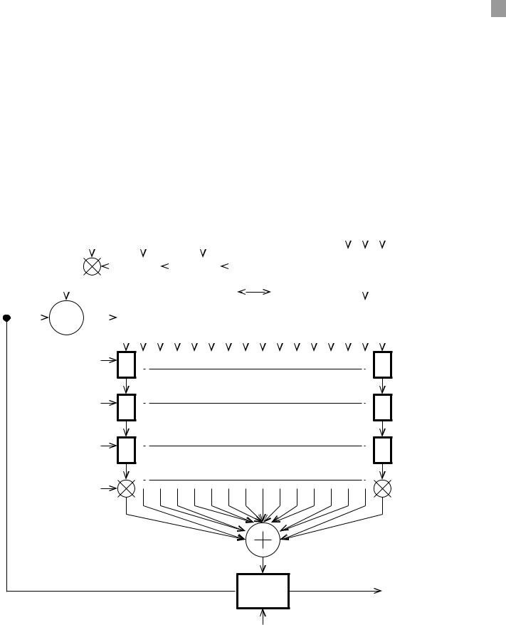
 STEREO RHYTHM DELAY SECTION
The stereo rhythm delay line has 16 time-delayed taps, each with its own resonant 2nd-order multi-mode state-variable filter and granular pitch shifter. The filters have independently adjustable resonance and cutoff frequency, and can be set to either lowpass, bandpass, highpass or bypass operation. The granular pitch shifters have a range of 15 semitones up to 16 semitones down.
Any one of the 16 taps can be selected to be fed back to the input for echo or regeneration effects. The feedback signal has a first order lowpass/highpass tone control filter and its own granular pitch shifter.
The tap delay times can range from 0.1 millisecond up to a maximum of 20 seconds. The overall delay times can be set either by manual entry with the rotary encoder, with a tap tempo entry, or through an external clock. The relative timings of the individual taps are set to one of 16 different preset “grooves”, or rhythms. The overall delay time can be modulated with an internal low frequency oscillator (LFO) with adjustable wave shape.
|
|
|
|
|
|
DELAY |
|
FEEDBACK |
|
FEEDBACK PITCH |
|
|
|
|
|
|
|
|
|
|
|
Level |
Rate Shape |
||||||||||||||||||||
|
|
|
|
|
|
FEEDBACK |
|
|
|
|
|
|
|
|
|
|
|
|
|
||||||||||||||||||||||||
|
|
|
|
|
|
LEVEL |
|
TONE |
|
|
|
|
SHIFT + DETUNE |
|
|
|
|
|
|
|
|
|
|
|
|
|
|
|
|
|
|
||||||||||||
|
|
|
|
|
|
|
|
|
|
|
|
|
|
|
|
|
|
|
|
|
|
|
|
|
|
|
|
|
|
|
|
|
|
|
|
|
|
|
|
|
|
|
|
|
|
|
|
|
|
|
|
|
|
|
|
|
|
|
|
|
|
|
|
|
|
|
|
|
|
|
|
|
|
|
|
|
|
|
|
|
|
|
|
|
|
|
|
|
|
|
|
|
|
|
|
|
|
|
|
|
|
|
|
|
|
|
|
|
|
|
|
|
|
|
|
|
|
|
|
|
|
|
|
|
|
Quadrature |
|
||||
|
|
|
|
|
|
|
|
|
|
|
|
|
|
|
|
|
|
|
|
|
|
|
|
|
|
|
|
|
|
|
|
|
|
|
|
|
|
|
|||||
|
|
|
|
|
|
|
|
|
|
|
|
|
|
|
|
|
|
|
|
|
|
|
|
|
|
|
|
|
|
|
|
|
|
|
|
|
|
Mod. LFO |
|
|
|
||
|
|
|
|
|
|
|
|
|
|
|
|
|
|
|
|
|
|
|
|
|
|
|
|
|
|
|
|
|
|
|
|
|
|
|
|
|
|
|
|
||||
|
|
|
|
|
|
|
|
|
|
|
|
|
|
|
|
|
|
|
|
|
|
|
|
|
|
|
|
|
|
|
|
|
|
|
|
|
|
|
|
|
|||
|
|
|
|
|
|
|
|
|
|
|
|
Tone Filter |
|
Pitch Shifter |
|
|
|
Feedback Tap |
|
|
|
|
|
|
|
|
|
|
|
||||||||||||||
RHYTHM DELAY INPUT |
|
|
|
|
|
|
|
|
|
|
|
|
|
|
|
|
|
|
|
|
|
|
|
|
|
|
|
|
|
|
|
|
|
|
|
|
|
|
|
|
|||
|
|
|
|
|
|
|
|
|
|
|
|
|
|
|
|
|
|
|
|
|
|
|
|
|
|
|
|
|
|
|
|
|
|
|
|
|
|
|
|
|
|||
|
|
|
|
|
|
|
|
|
|
|
|
|
|
|
|
Rhythm Delay Line |
|
|
|
|
|
|
|
|
|
|
|
||||||||||||||||
|
|
|
|
|
|
|
|
|
|
|
|
|
|
|
|
|
|
|
|
|
|
|
|
||||||||||||||||||||
|
|
|
|
|
|
|
|
|
|
|
|
|
|
|
|
|
|
|
|
|
|
|
|
|
|
|
|
|
|
|
|
|
|||||||||||
|
|
|
|
|
|
|
|
|
|
1 |
2 |
3 |
|
4 |
5 |
6 |
|
7 |
8 |
9 |
10 |
11 |
12 |
13 |
14 |
15 |
16 |
|
|||||||||||||||
|
|
|
|
|
|
|
|
|
|
|
|
|
|||||||||||||||||||||||||||||||
|
|
|
|
|
|
|
|
|
|
|
|
|
|
|
|
|
|
|
|
|
|
|
|
|
|
|
|
|
|
|
|
|
|
|
|
|
|
|
|
|
|
|
|
Pitch Shift, Detune |
PS1 |
|
|
Pan/Balance |
PB1 |
|
Cuto Frequency
Resonance (Q) F1
Type
Level
Mute
|
PS16 |
PITCH SHIFTERS |
|
STEREO PAN/BALANCE CONTROLS |
PB16 |
|
|
MULTI-MODE (LP, BP, HP) 2nd ORDER FILTERS |
F16 |
|
RHYTHM DELAY OUTPUT
 CROSSFADER
WET/DRY
Figure 1. Rhythm delay section block diagram.
4
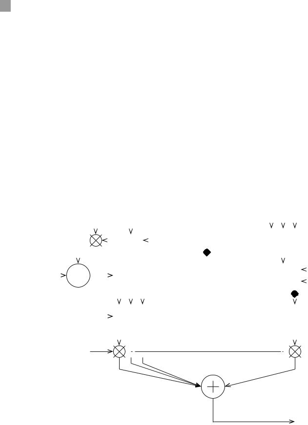
STEREO RESONANT COMB FILTER SECTION
The stereo comb resonator section has 64 time-delayed taps which are summed together. This produces a deep comb filter or resonating effect. At large comb sizes (long time delays) a multiple echo effect is produced. The density of the resonator can be varied from 1 tap all the way up to 64 taps.
The relative timing of the 64 taps are set according to one of 16 different preset patterns, which provide different resonator timbres or echo rhythms. The comb size can be set either with the rotary encoder, an external clock or through a transposable 1v/oct input voltage. The comb size can be modulated with an internal low frequency oscillator (LFO) with adjustable wave shape.
The tap with the longest delay time (tap 64) is fed back to the input. The amount of signal being fed back is adjustable. High feedback levels, with short comb sizes, can produce “Karplus-Strong” types of plucked string sounds. The feedback signal passes through a simple fixed low pass filter and a selectable nonlinearity. The nonlinearity can provide a different quality to the resonant sound when the feedback level is high.
|
|
|
|
COMB |
COMB |
|
|
|
|
|
Level Rate Shape |
||||||||||||||
|
|
|
|
FEEDBACK |
FEEDBACK |
||||||||||||||||||||
|
|
|
|
LEVEL |
NONLINEARITY & FILTER |
|
|
|
|
|
|
|
|
||||||||||||
|
|
|
|
|
|
|
|
|
|
|
|
|
|
|
|
|
|
|
|
|
|
|
|
|
|
|
|
|
|
|
|
|
|
|
|
|
|
|
|
|
|
|
|
|
|
|
|
|
|
|
|
|
|
|
|
|
|
|
|
|
|
|
|
|
|
|
|
|
|
|
Quadrature |
|
|
|
|
||
|
|
|
|
|
|
|
|
|
|
|
|
|
|
|
|
|
|
|
|
|
|
||||
|
|
|
|
|
|
|
|
|
|
|
|
|
|
|
|
|
|
|
Mod. LFO |
|
|
|
|
||
|
|
|
|
|
|
|
|
|
|
|
|
|
|
|
|
|
|
|
|
|
|
||||
|
|
|
|
|
|
|
|
|
|
|
|
|
|
|
|
|
|
|
|
|
|
|
|
||
COMB INPUT |
|
|
|
|
|
|
|
Feedback Filter |
|
|
|
|
|
|
|
|
|
COMB SIZE |
|||||||
|
|
|
|
|
|
|
|
|
|
|
|
|
|
|
|
|
|
|
|
|
|
||||
|
|
|
|
|
|
|
|
|
|
|
|
|
|
|
|
|
|
|
|
|
|
||||
|
|
|
|
|
|
|
|
|
Comb Delay Line |
|
|
|
|
|
|
|
|||||||||
|
|
|
|
|
|
|
|
|
|
|
|
|
|
|
|
|
|
|
|||||||
|
|
|
|
|
|
|
|
|
1 |
2 |
3 |
64 |
|
|
|
TAP PATTERN |
|||||||||
|
|
|
|
|
|
|
|
|
|
|
|
|
|
|
|||||||||||
|
|
|
|
|
|
|
|
|
|
|
|
|
|
|
|||||||||||
|
|
|
|
|
|
|
|
|
- - - - - - - - - - - - - - - - - - - - - - - - - - - |
- |
- - - - - - - - - - - - - - - - - - - - - - - - - - - - |
|
|
|
|
||||||||||
|
|
|
|
|
|
|
|
|
|
|
|
|
|
|
|
|
|
|
|
|
|
|
|
|
|
|
|
|
|
|
|
|
|
|
|
|
|
|
|
|
|
|
|
|
|
|
|
|
Feedback is taken |
||
|
|
|
|
|
|
|
|
|
|
|
|
|
|
|
|
|
|
|
|
|
|
|
from Tap 64 |
||
|
|
|
|
|
|
|
|
|
|
|
|
|
|
|
|
|
|
|
|
|
|
||||
|
|
#TAPS |
|
|
|
|
|
|
|
|
Tap Selection Switches |
|
|
|
|
|
|
|
|
||||||
|
|
|
|
|
|
|
|
|
|
|
|
|
|
|
|
|
|||||||||
|
|
|
|
|
|
|
|
|
|
|
|
|
|
|
|
|
|
|
|
|
|
|
|
|
|
|
|
|
|
|
|
|
|
|
|
|
|
|
|
|
|
|
|
|
|
|
|
|
|
|
|
|
|
|
|
|
|
|
|
|
|
|
|
|
|
|
|
|
|
|
|
|
|
|
|
|
|
SLOPE
COMB OUTPUT
Figure 2. Comb resonator section block diagram.
5
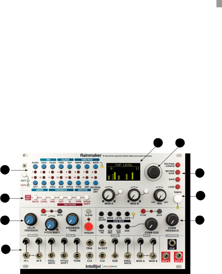
 FRONT PANEL ELEMENTS
A user of the Rainmaker module interacts with it through the module’s front panel. The elements comprising the user interface are one of six types: BUTTONS, OLED DISPLAY, LEDs, POTENTIOMETERS, ROTARY ENCODER, JACKS.
Information about the various parameter values and module configuration is provided by the LEDs (light emitting diodes) and by the OLED (organic light emitting diode) display (item 1 in the figure below).
Most of the buttons on the Rainmaker front panel select various parameters to be displayed and/or edited. Some buttons change the operational mode of the module, such as the FX ON, MUTE, and EDIT/TAP# buttons. The other buttons execute various functions, such as the TEMPO, CLEAR and TRIGGER buttons.
The module contains eight large rotary potentiometers. These are the blue, white, and black knobs with a small indicator mark on top. They allow the user to quickly change important parameters of the module, such as feedback settings. There are also nine small rotary potentiometers (the thin black shafts will small white indicator marks on top) which are used to attenuate the external input signals. The potentiometers will typically be used during performances to dynamically change the behaviour of the module’s effects.
The primary means for user setting of the module parameters is via the digital rotary encoder (item 2 in the figure below). Unlike the potentiometers, the rotary encoder can be turned indefinitely. Turning the encoder is typically used to change parameters as indicated in various displays. The rotary encoder can also be pushed, which engages a switch. This is used to initiate various actions, such as saving or loading of a preset.
1 2
3 |
9 |
|
4 |
8 |
|
5 |
7 |
6
Figure 3. Rainmaker module front panel.
6

 The functions of the various front panel elements are described in the following sections.
Global Rhythm Delay Parameter Editing
w
●● EDIT/TAP# Pressing the EDIT/TAP# button alternates between EDIT mode and TAP# mode. In TAP# mode, the numbered blue buttons in the upper left of the module select which tap is being edited, while when in EDIT mode the buttons select various rhythm delay parameters to be edited. The associated parameters are described in the following sections.
●● 1 - RAND Displays the current destination of the randomization action (i.e. which parameters of the module will be randomized). The currently active destination is selected from the list of possible choices by turning the rotary encoder. The available destinations are listed in the table below. When in this display mode, pressing the rotary encoder switch (by pushing on the rotary encoder) will execute a single randomization action on the currently selected destination. Also, if the TRIGGER MODE (see later in the manual) is set to Randomize, then pressing the big red TRIGGER button or receipt of a positive pulse in the external TRIG input will cause the execution of a single randomization action.
Rand. Destination |
Description |
|
|
|
|
|
The relative timings of the 16 rhythm delay taps will be perturbed from |
|
Groove times |
their current values. The altered groove times are not saved in presets, |
|
|
however. |
|
Tap mutes |
The per-tap mutes are randomly turned on or off. This is useful for ran- |
|
domly selecting taps without affecting their levels. |
||
|
||
|
|
|
Tap levels |
The per-tap levels are randomized. |
|
|
|
|
Tap pans |
The left-right pans/balances of the taps are randomized. |
|
|
|
|
Tap filter cuts |
The cutoff frequency of each tap’s filter is randomized. This has no effect |
|
on the sound if the filter type is set to NONE. |
||
|
||
|
|
|
Tap filter Qs |
The resonance (Q) of each tap’s filter is randomized. This has no effect on |
|
the sound if the filter type is set to NONE. |
||
|
||
|
|
|
Tap filter types |
The type of the multi-mode filter for each tap is randomly set to one of |
|
NONE, LP (lowpass), BP (bandpass), or HP (highpass). |
||
|
||
|
|
|
Tap pitch shifts |
The pitch shift applied to each tap output is randomly set to an integer |
|
value between -16 and +15 semitones. |
||
|
||
|
|
|
Tap detunes |
The detuning (slight pitch shift amount) applied to each tap is randomly |
|
set to a value from -32 to +31 (a value of 32 corresponds to one semitone) |
||
|
||
|
|
7

|
|
Rand. Destination |
Description |
|
|
|
|
||||
|
|
|
|
|
|
All taps |
The per-tap parameters (MUTE,LEVEL,PAN,CUT,Q,TYPE,PITCH SHIFT, |
|
DETUNE) are all randomized. |
||
|
||
|
|
|
All delay |
All fo the rhythm delay global parameters are randomized, except for |
|
RAND. DESTINATION, TIME, and WET/DRY amount. |
||
|
||
|
|
|
All taps & delay |
All the per-tap and global rhythm delay parameters are randomized (i.e. |
|
the combination of the two previous settings - All taps and All delay). |
||
|
||
|
|
|
All comb |
All of the comb resonator section parameters are randomized, except for |
|
COMB SIZE and CLK SRC. |
||
|
||
|
|
|
All delay & comb |
All the global rhythm delay parameters and all the comb parameters are |
|
randomized. |
||
|
||
|
|
|
All |
All the per-tap and global rhythm delay parameters and all the comb pa- |
|
rameters are randomized. |
||
|
||
|
|
●● 2 - TAP : GRID Displays the current GRID and PILES settings. Turning the rotary encoder will change the GRID value. The GRID value defines the relation between the BEAT TIME and the nominal tap delay times according to the formula : (tap delay time = BEAT TIME * tap number/ GRID). GRID values are expressed in multiples of Taps/Beat. As an example, if the GRID value is 4 / beat, this means that the nominal delay time for tap #4 will be equal to the BEAT time, the nominal delay time for tap #8 will be equal to twice the BEAT time, and so on. The BEAT TIME is the time value shown in the CLOCK : TIME display screen. The actual delay time for a tap will deviate from its nominal value depending on the selected GROOVE TYPE and GROOVE amount. Possible GRID values are 1, 2, 3, 4, 6, 8, 12 and 16.
●● 3 - TAP : PILES Displays the current GRID and PILES settings. Turning the rotary encoder will change the number and size of the tap piles. A tap “pile” is a collection of taps that are all given the same delay time, which will be the delay time of the last tap in the pile. Making piles of taps is useful when you want to apply multiple effects at a given time. For example, you can make a four-note Major 7th chord by selecting 4 piles of 4 taps, setting the levels of taps #1, 2, 3 and 4 to maximum with all other taps muted or set to zero level, and setting tap #1 to have a pitch shift of 0, tap #2 to have a pitch shift of +4, tap #3 to have a pitch shift of +7, and tap #4 to have a pitch shift of +11. Then an input sound will be echoed with a delay time equal to the tap delay time for tap #4, but will be harmonized as a Maj7 chord.
●● 4 - CLOCK : TIME Displays the current beat time in milliseconds and in beats per minute (BPM), as well as the clock division factor. Turning the rotary encoder will change the beat time. If there is a clock signal connected to the (left-hand) CLK input, the beat time will follow the clock period, multiplied by the clock division factor, and the rotary encoder will have no effect. The beat time can also be changed by pushing the large white TEMPO button repeatedly. Pushing on the encoder while rotating it will change the Time value in larger increments, to speed up going from one time setting to another.
8
 ●● 5 - CLOCK : DIV Displays the current beat time in milliseconds and in beats per minute (BPM), as well as the clock division factor. Turning the rotary encoder will change the DIV (clock division factor) value. When a clock signal is connected to the (left-hand) CLK input jack the beat time will follow the period of the clock signal, multiplied by the DIV value. Possible DIV settings are /1, /2, /3, /4, /6, /8, /12, /16, /24, /32, /48, /64, /96, /128, /192, /256.
●● 6 - TIME MOD : WAVE Displays the waveshape, level, and rate of the rhythm delay time modulation LFO (low-frequency oscillator). Turning the rotary encoder will change the shape of the modulating waveform. Possible settings are : OFF (no modulation), Sinusoid, Triangle, Vibrato 1, Vibrato 2 (a faster vibrato), Down Chirp (a sinewave with decaying frequency), Up Chirp (a sinewave with increasing frequency), Random.
●● 7 - TIME MOD : LEVEL Displays the waveshape, level, and rate of the rhythm delay time modulation LFO. Turning the rotary encoder will change the amount of modulation applied to the tap delay times. The Level setting ranges from 0 (no modulation) to 15 (time modulation of 10 msec in amplitude).
●● 8 - TIME MOD : RATE Displays the waveshape, level, and rate of the rhythm delay time modulation LFO. Turning the rotary encoder varies the period or rate of the modulation LFO. Rate values are displayed in Hertz (Hz). Pushing on the encoder while rotating it will change the Rate value in larger increments, to speed up going from one rate setting to another.
●● 9 - GRAIN : QTY Displays the number and size of grains used by the granular pitch shifters. Turning the rotary encoder changes the number of grains (Quantity). Possible choices are 1, 2, 4, and 1, no envelope. The grain shape is triangular for the first 3 settings, but is rectangular for the final setting (1, no envelope). If more than 1 grain is used, the grains will overlap in time. For Quantity = 2 the overlap is fixed at 50%. In the case of Quantity = 4 the overlap is nominally 25%, but there is a small random shift in time for each grain. This is added to prevent excessive comb filtering that would otherwise result.
●● 10 - GRAIN : SIZE Displays the number and size of grains used by the pitch shifters. Turning the rotary encoder changes the size (time interval) of each grain. Possible choices are 5 msec, 10 msec, 21 msec, 42 msec, 84 msec, 168 msec, and 336 msec.
●● 11 - FEEDBACK : TAP# Displays the left and right channel feedback tap numbers, and the feedback time slip amount. When first entering this display page, the left channel’s feedback tap# is highlighted. Pressing the button again will highlight the right channel feedback tap#. When Tap# L is highlighted, turning the rotary encoder will change both the L and R feedback tap#s. When Tap# R is highlighted then only the Tap# R value will change. Possible values range from 1 to 16, indicating that feedback is taken from the associated delay line tap. There are two additional settings available, however. When set to “ALL”, the feedback is taken from the post-filter, post-tap-mix output. In this case there is no pitch shifting applied. When set to “COMB SIZE” the feedback is taken from a variable position tap whose delay time is set to be equal to the COMB SIZE parameter. This allows the COMB SIZE controls (e.g. the 1V/oct input) to adjust the feedback time. This can be used to provide short, tuned, feedback effects without altering the rhythm of the 16 rhythm delay line taps.
●● 12 - FEEDBACK : SLIP Displays the left and right channel feedback tap numbers, and the feedback time slip amount. Turning the rotary encoder will fine tune the feedback delay time either ahead or behind the selected tap’s delay time. This can be used to provide “rushing/dragging” echo effects. Possible values range from -16 to 0 (no offset) to +15. The extreme settings (-16 and +15) provide an offset of 1/2 the nominal delay interval (the interval with the groove amount set to 0) between taps.
9
 ●● 13 - FEEDBACK : PITCH Displays the pitch shift and detune amounts for the left and right feedback channels. When this display page is first entered, the Pitch L parameter is highlighted, and turning the rotary encoder will change both the Pitch L and Pitch R values. Pressing the button again will highlight the Pitch R parameter. Turning the rotary encoder will then change only the Pitch R value. Pressing the button again will highlight the Detune L parameter, and turning the rotary encoder will change both the Detune L and Detune R parameters. Pressing the button again will highlight the Detune R parameter, and turning the rotary encoder will change only the Detune R parameter. Pressing the button once more will bring the display back to the initial case, where the Pitch L parameter is highlighted.
●● 14 - GROOVE : TYPE Displays the GROOVE type and the GROOVE amount. Turning the rotary encoder changes the groove type. A groove is a set of relative timings for the 16 rhythm delay taps. The simplest groove is the “Straight” groove, in which the taps are evenly spaced in time. In the “Swing” groove the time interval between taps alternate between one-third of a beat and two-thirds of a beat. There are 16 different groove types available, as listed in the following table. The timings shown in the table are approximate - the actual timings have a higher resolution.
Groove Type |
Groove Timing Pattern |
|
|
Straight
Swing
Hard Swing
Reverse Swing
Alternate Swing
Accelerando
Ritardando
Waltz Time
Half Swing
Roller Coaster
10
|
|
Groove Type |
Groove Timing Pattern |
|
|||
|
|
|
|
Quintuple Time
Uniform Random1
Uniform Random2
Uniform Random3
Early Reflection
Late Reflection
●● 15 - GROOVE : AMT Displays the groove amount. A groove amount of 0 gives the default “Straight” groove pattern, where the tap delay times are equally spaced. A groove amount of 100 gives the selected Groove type pattern. Groove amounts between 0 and 100 provide a blending of the Straight and selected Groove type patterns. This is useful, for example, when adjusting the amount of “Swing”, when the Groove type is set to “Swing”. Turning the rotary encoder changes the groove amount. Pressing down on the rotary encoder while turning it increases the encoder step size to speed up the entry.
●● 16 - REVERSE+WET/DRY Displays whether the Reverse effect is on or off, and the internal rhythm delay wet/dry mix. When this display page is first entered, the Reverse mode is highlighted and turning the rotary encoder clockwise turns the Reverse effect ON, while turning it counter-clockwise turns the effect OFF. When Reverse is turned ON, the input buffer is played back in reverse through the rhythm delay line for a time equal to the feedback tap time. At the end of this time the playback jumps to the current time and starts playing backwards again. See the diagram on the next page for a depiction of the reverse mode’s opreation. The reverse mode can also be turned on or off with the TRIGGER button or TRIG signal (see the description of the TRIGGER action later in the manual).
When the REVERSE-WET/DRY button is pressed again, the Wet/Dry mix will be highlighted. Turning the rotary encoder will change the Wet/Dry value. The Wet/Dry mix adjusts the mixing of the input and the output of the rhythm delay line. This is useful, for example, when the module is configured to have the rhythm delay follow the comb resonator. The effect of the internal rhythm delay wet/dry mixer is distinct from that of the global Wet/Dry mix control located on the module’s front panel. That control adjusts the mixing of the module’s overall input (from the two jacks INL and INR located on the lower left had part of the panel) and the module’s overall output.
11
 Loading...