

Page 1

µMOD II Manual
µMOD II
Ring Modulator / Analog Logic
Manual Revision: 1.0
Page 2

µMOD II Manual
Table of Contents
Table of Contents
Overview
Installation
Before Your Start
Installing Your Module
Front Panel
Controls
Inputs & Outputs
Analog Logic
Technical Specifications
Page 1
Page 3

µMOD II Manual
Overview
The µMod II is a multi-function module designed for combining audio or CV signals in a variety
of ways. Apart from a versatile ring modulator / four quadrant multiplier it also performs analog
logic functions useful for generating new combinations of waveforms.
The principle of operation is to take two signals, called X and Y, and produce a series of output
signals that are derived from the sources using a variety of analog methods.
Page 2
Page 4

µMOD II Manual
Installation
Intellijel Eurorack modules are designed to be used with a Eurorack-compatible case and power
supply.
Before Your Start
Before installing a new module in your case you must ensure your case’s power supply has
sufficient available capacity to power the module:
● Sum up the specified +12V current draw for all modules, including the new one. Do the
same for the -12 V and +5V current draw. The current draw will be specified in the
manufacturer's technical specifications for each module.
● Compare each of the sums to specifications for your case’s power supply.
● Only proceed with installation if none of the values exceeds the power supply’s
specifications. Otherwise you must remove modules to free up capacity or upgrade your
power supply.
You will also need to ensure you have enough free space (hp) as well as free power headers in
your case to fit the new module.
You can use a tool like ModularGrid to assist in your planning. Failure to adequately power your
modules may result in damage to your modules or power supply. If you are unsure, please
contact us before proceeding.
Installing Your Module
When installing or removing a module from your case always turn off the power to the case and
disconnect the power cable. Failure to do so may result in serious injury or equipment damage.
Ensure the 10-pin connector on the power cable is connected correctly to the module before
proceeding. The red stripe on the cable must line up with the -12V pins on the module’s power
connector. The pins are indicated with the label -12V, a white stripe next to the connector, the
words “red stripe”, or some combination of those indicators.
Page 3
Page 5

µMOD II Manual
Most modules will come with the cable already connected but it is good to double check the
orientation. Be aware that some modules may have headers that serve other purposes so
ensure the cable is connected to the right one.
The other end of the cable, with a 16-pin connector, connects to the power bus board of your
Eurorack case. Ensure the red stripe on the cable lines up with the -12V pins on the bus board.
On Intellijel power supplies the pins are labelled with the label “-12V” and a thick white stripe:
Page 4
Page 6
µMOD II Manual
If you are using another manufacturer’s power supply, check their documentation for
instructions.
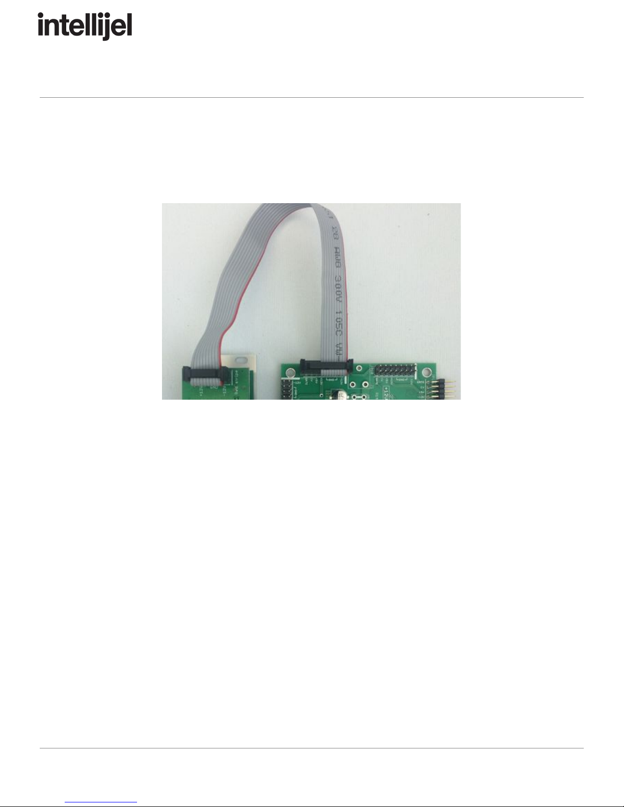
Once connected, the cabling between the module and power supply should resemble the
picture below:
Before reconnecting power and turning on your modular system, double check that the ribbon
cable is fully seated on both ends and that all the pins are correctly aligned. If the pins are
misaligned in any direction or the ribbon is backwards you can cause damage to your module,
power supply, or other modules.
After you have confirmed all the connections, you can reconnect the power cable and turn on
your modular system. You should immediately check that all your modules have powered on
and are functioning correctly. If you notice any anomalies, turn your system off right away and
check your cabling again for mistakes.
Page 5
Page 7

µMOD II Manual
Front Panel
Controls
1. QUADRANT - The quadrant knob controls shifts the multiplication in to the positive or
negative quadrants. For standard ring modulation, set the knob at the 12 o’clock
position.
Page 6
Page 8

µMOD II Manual
2. X +/- - This three position switch controls the rectification of the X input. When in the
middle position the input waveform is unaltered. When at + only the positive half of the
waveform is passed through. When at – only the negative half is passed through.
3. Y +/- - This switch functions the same as the X +/- but for the Y channel.
4. X Attenuator - This knob controls the attenuation of the X signal. It is unaltered when
the knob is fully clockwise.
5. Y Attenuator - This knob functions the same as the X attenuator but for the Y channel.
Inputs & Outputs
A. X - X signal input.
B. Y - Y signal input.
C. RING - Ring modulator output.
D. SUM - This output is the result of adding the X and Y inputs, X + Y.
E. DIFF - This output is the result of subtracting the X input from the Y input, Y – X.
F. MAX - This output is the maximum of the X and Y signals at any given point in time. It’s
the analog equivalent of the digital OR operation.
G. MIN - This output is the minimum of the X and Y signals at any given point in time. It’s
the analog equivalent of the digital AND operation.
Page 7
Page 9
µMOD II Manual
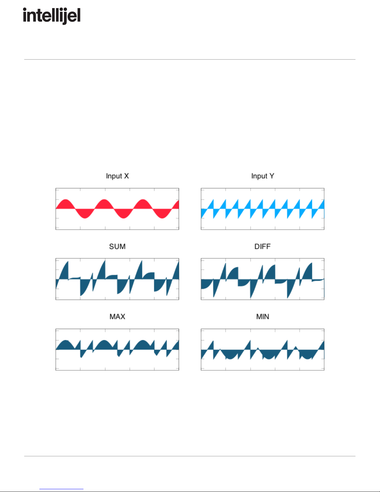
Analog Logic
The analog logic section of the module produces waveforms that are a combination of the X and
Y inputs. This is well suited to creating complex CV from basic waveforms, or creating new
interesting forms of audio.
The diagram below illustrates what’s possible by combining sine and saw waveforms of two
different frequencies via the various logic outputs:
Page 8
Page 10

µMOD II Manual
Technical Specifications
Width
6 hp
Maximum Depth
35 mm
Current Draw
41 mA @ +12V
41 mA @ -12V
Page 9
 Loading...