

Page 1
Intellijel KORGASMATRON II
Illustrated supplement
by Demonam
Page 2

Index
01... LP2 / 2-pole low-pass filter
02... LP1 / 1-pole low-pass filter
03... BP1 / 1-pole band-pass filter
04... HP1 / 1-pole high-pass filter
05... HP2 / 2-pole high-pass filter
06... BR1 / 1-pole band-reject filter
07... Dual 1V/Oct sine oscillator
08... Normalled inputs
09... SERIAL configuration
10... PARALLEL configuration
11... XFADE response - 01
12... XFADE response - 02
13... State-variable stereo filter
14... State-variable stereo filter - VC pan patch
15... 1-pole BAND-PASS filter patch
16... 1-pole BAND-PASS filter curves
17... 2-pole BAND-PASS filter patch
18... 2-pole BAND-PASS filter curves
19... 1-pole BAND-REJECT filter patch
20... 1-pole BAND-REJECT filter curves
21... 2-pole BAND-REJECT filter patch
22... 2-pole BAND-REJECT filter curves
23... Asymmetrical BAND-PASS filter patch
24... Asymmetrical BAND-PASS filter curves
25... Asymmetrical BAND-REJECT filter patch
26... Asymmetrical BAND-REJECT filter curves
27... Dual BAND-PASS filter patch
28... Dual BAND-PASS filter curves
29... Dual BAND-REJECT filter patch
30... Dual BAND-REJECT filter curves
31... (BP1 + LP1) filter patch
32... (BP1 + LP1) filter curves
33... (BP1 + LP2) filter patch
34... (BP1 + LP2) filter curves
35... (BP1 + HP1) filter patch
36... (BP1 + HP1) filter curves
37... (BP1 + HP2) filter patch
38... (BP1 + HP2) filter curves
39... (BR1 + LP1) filter patch
40... (BR1 + LP1) filter curves
41... (BR1 + LP2) filter patch
42... (BR1 + LP2) filter curves
43... (BR1 + HP1) filter patch
44... (BR1 + HP1) filter curves
45... (BR1 + HP2) filter patch
46... (BR1 + HP2) filter curves
47... Heavy dub bass
48... Ping !
49... Weird filter
50... Spacewave sound
51... Feedback loop
52... Cross-FM
53... Feedback FM loop
54... Drone zone 1
55... Expander - Overview
56... Expander - VC Q filtering
57... Expander - Quad filter
58... Expander - Quad filter feedback loop
59... Expander - Cross-Q modulation
60... Expander - Feedback cross-Q modulation
61... Expander - Drone zone 2
Page 3
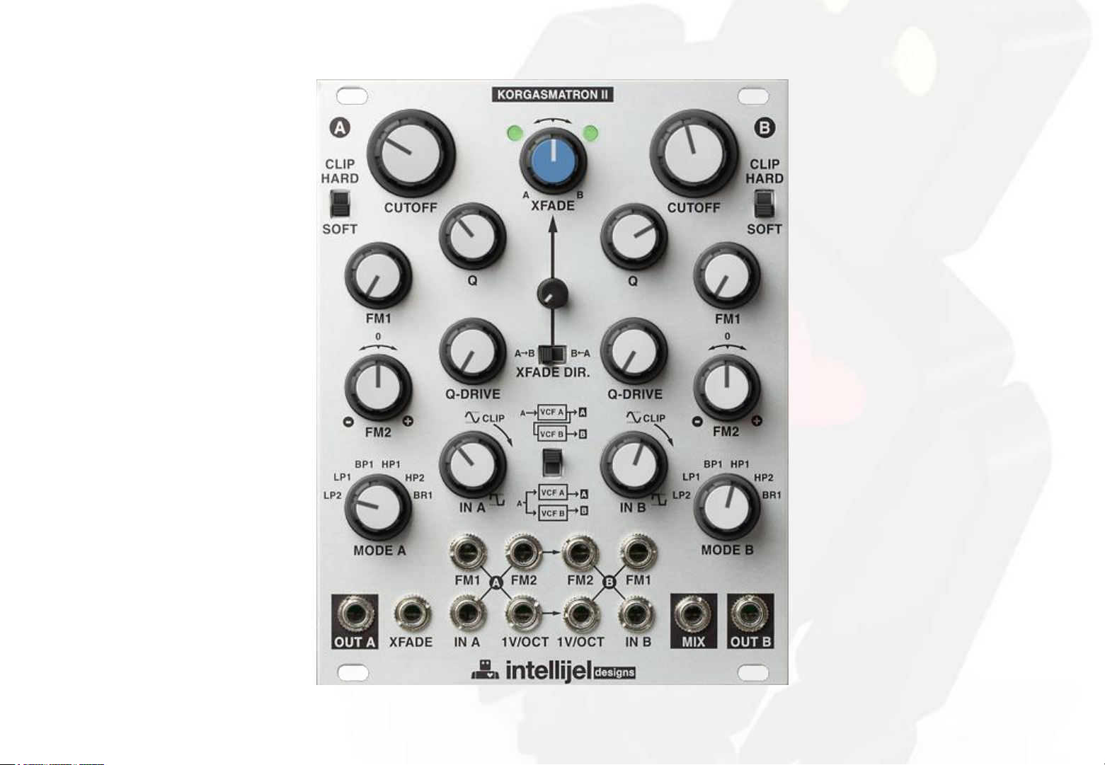
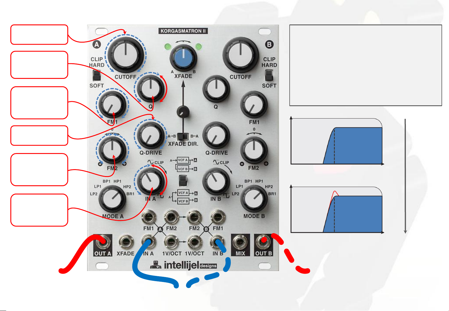
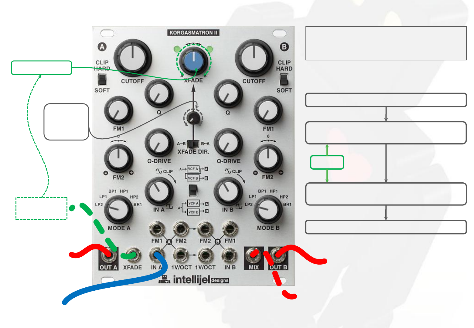
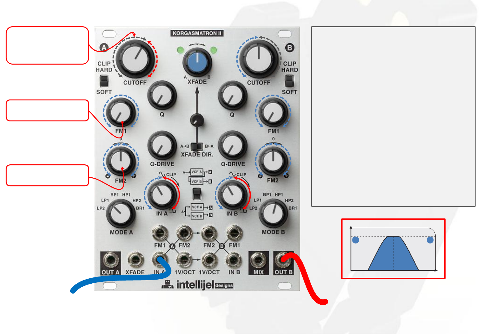
LP2 / 2-pole low-pass filter
set filter cutoff
frequency
set resonance
self-oscillate
past 1 o'clock
unipolar
attenuator
for
FM1 input
set level of
resonance
bipolar
attenuator
for
FM2 input
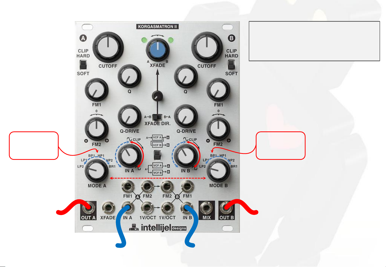
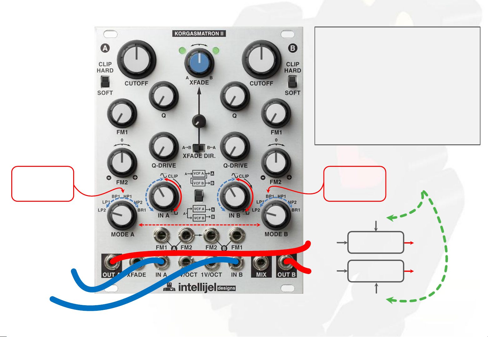
Input attenuator IN A (and/or B) controls the level
into the filter A (and/or B).
For classic tone keep this below 12 oʼclock.
Higher gain will suppress the resonance of the
filter and change its tone.
The combination of IN A level, Q and Q Drive knobs
can alter the tone of the filter dramatically from
sweet to scathing - experiment!
out
freq.
cutoff
increase
out
Q
gain unipolar
attenuator
for
signal A input
filter A out
freq.
cutoff
filter B out
signal(s) to be filtered
01
Page 4
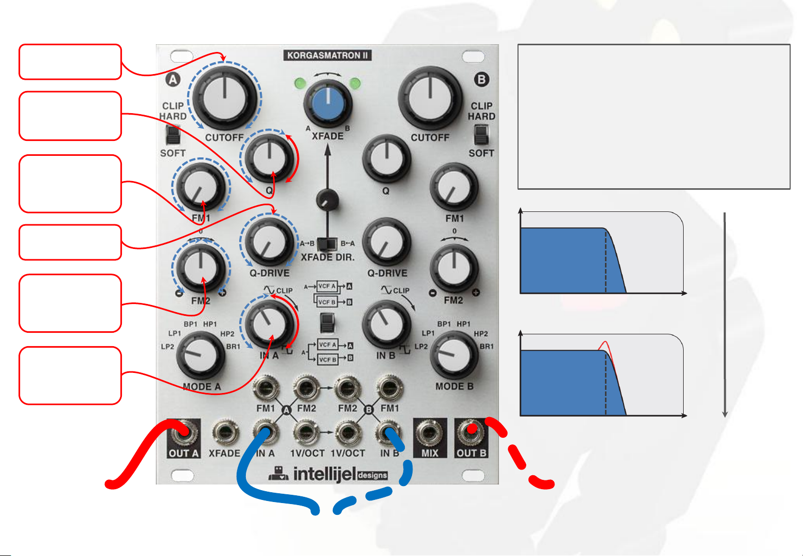
LP1 / 1-pole low-pass filter
set filter cutoff
frequency
set resonance
self-oscillate
past 1 o'clock
unipolar
attenuator
for
FM1 input
set level of
resonance
bipolar
attenuator
for
FM2 input
Input attenuator IN A (and/or B) controls the level
into the filter A (and/or B).
For classic tone keep this below 12 oʼclock.
Higher gain will suppress the resonance of the
filter and change its tone.
The combination of IN A level, Q and Q Drive knobs
can alter the tone of the filter dramatically from
sweet to scathing - experiment!
out
freq.
cutoff
increase
out
Q
gain unipolar
attenuator
for
signal A input
filter A out
freq.
cutoff
filter B out
signal(s) to be filtered
02
Page 5
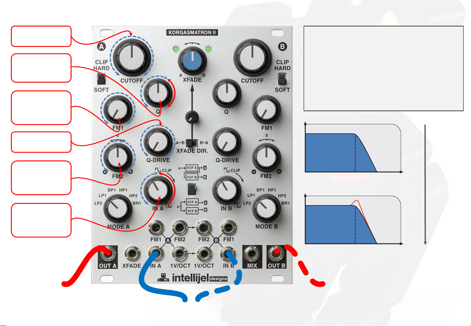
BP1 / 1-pole band-pass filter
set filter cutoff
frequency
set resonance
self-oscillate
past 1 o'clock
unipolar
attenuator
for
FM1 input
set level of
resonance
bipolar
attenuator
for
FM2 input
Input attenuator IN A (and/or B) controls the level
into the filter A (and/or B).
For classic tone keep this below 12 oʼclock.
Higher gain will suppress the resonance of the
filter and change its tone.
The combination of IN A level, Q and Q Drive knobs
can alter the tone of the filter dramatically from
sweet to scathing - experiment!
out
freq.
cutoff
increase
out
Q
gain unipolar
attenuator
for
signal A input
filter A out
freq.
cutoff
filter B out
signal(s) to be filtered
03
Page 6

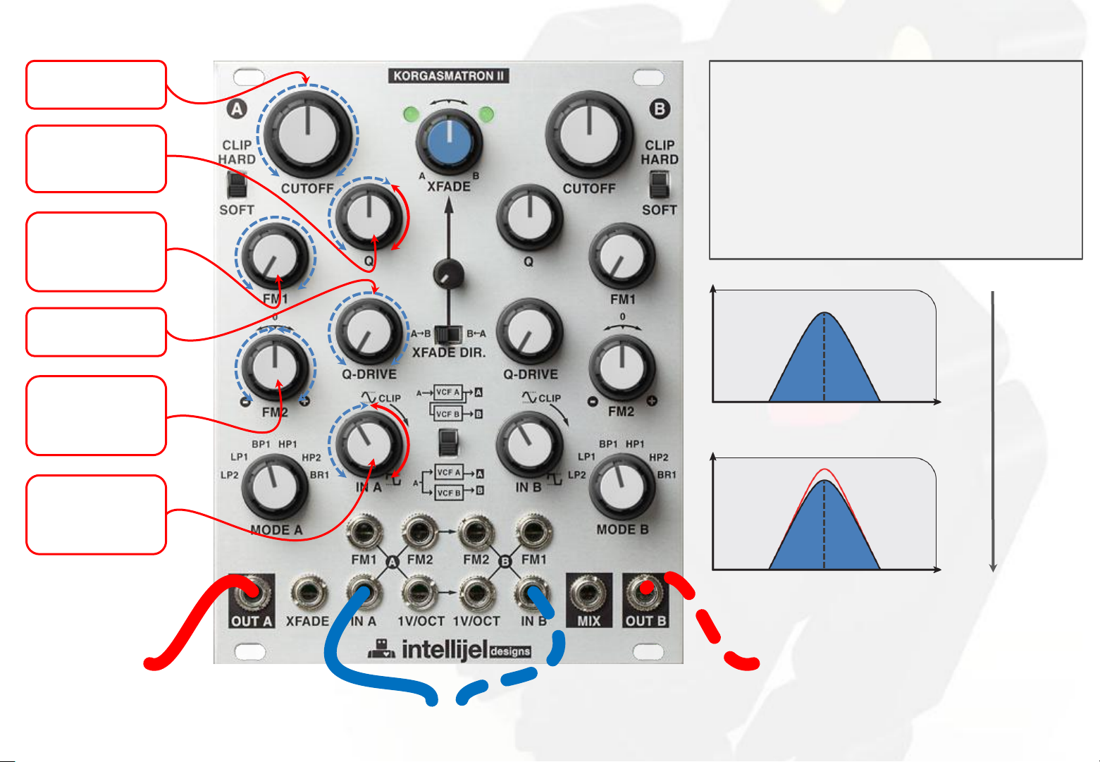
HP1 / 1-pole high-pass filter
set filter cutoff
frequency
set resonance
self-oscillate
past 1 o'clock
unipolar
attenuator
for
FM1 input
set level of
resonance
bipolar
attenuator
for
FM2 input
Input attenuator IN A (and/or B) controls the level
into the filter A (and/or B).
For classic tone keep this below 12 oʼclock.
Higher gain will suppress the resonance of the
filter and change its tone.
The combination of IN A level, Q and Q Drive knobs
can alter the tone of the filter dramatically from
sweet to scathing - experiment!
out
freq.
cutoff
increase
out
Q
gain unipolar
attenuator
for
signal A input
filter A out
freq.
cutoff
filter B out
signal(s) to be filtered
04
Page 7
HP2 / 2-pole high-pass filter
set filter cutoff
frequency
set resonance
self-oscillate
past 1 o'clock
unipolar
attenuator
for
FM1 input
set level of
resonance
bipolar
attenuator
for
FM2 input
Input attenuator IN A (and/or B) controls the level
into the filter A (and/or B).
For classic tone keep this below 12 oʼclock.
Higher gain will suppress the resonance of the
filter and change its tone.
The combination of IN A level, Q and Q Drive knobs
can alter the tone of the filter dramatically from
sweet to scathing - experiment!
out
freq.
cutoff
increase
out
Q
gain unipolar
attenuator
for
signal A input
filter A out
freq.
cutoff
filter B out
signal(s) to be filtered
05
Page 8
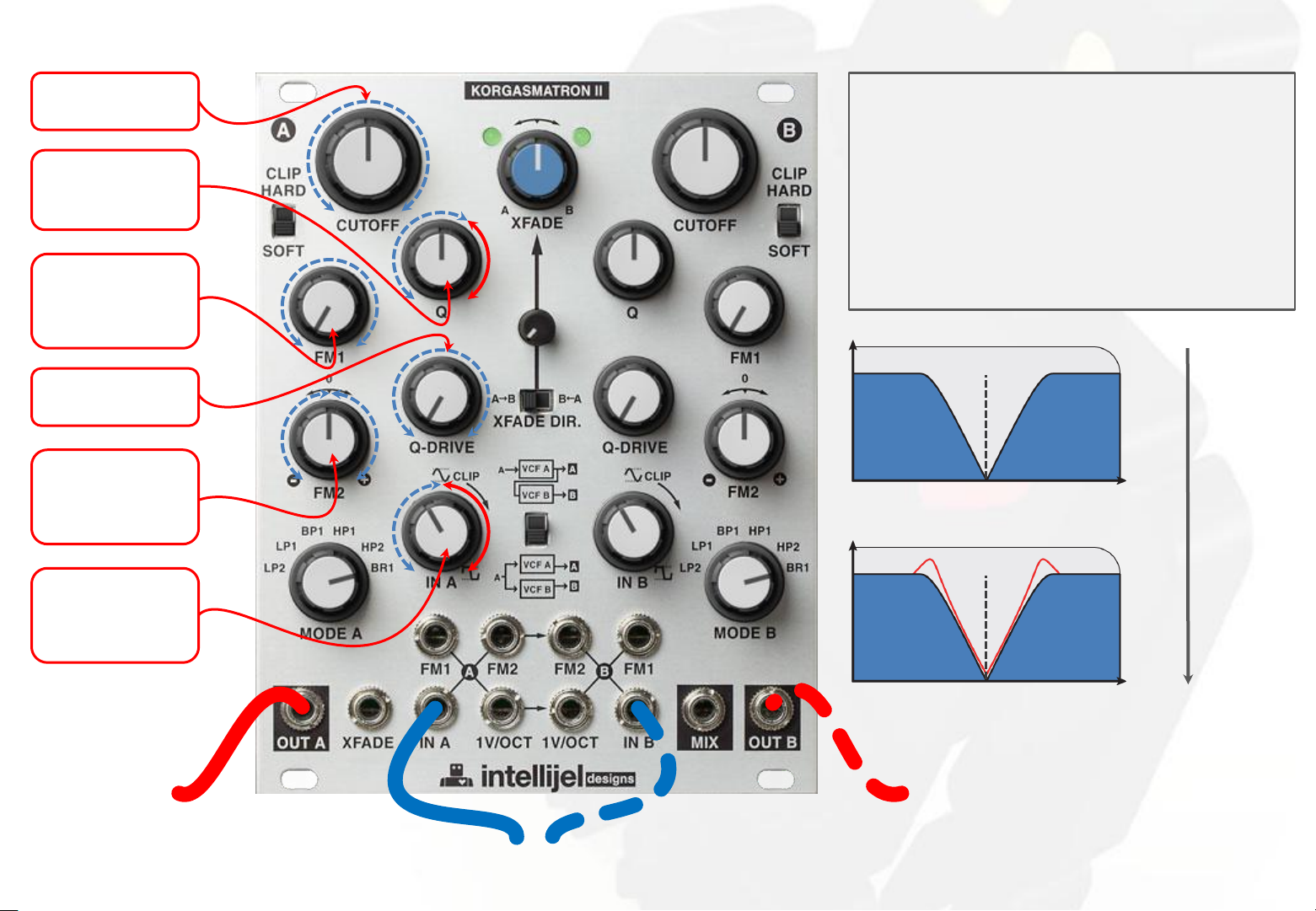
BR1 / 1-pole band-reject filter
set filter cutoff
frequency
set resonance
self-oscillate
past 1 o'clock
unipolar
attenuator
for
FM1 input
set level of
resonance
bipolar
attenuator
for
FM2 input
Input attenuator IN A (and/or B) controls the level
into the filter A (and/or B).
For classic tone keep this below 12 oʼclock.
Higher gain will suppress the resonance of the
filter and change its tone.
The combination of IN A level, Q and Q Drive knobs
can alter the tone of the filter dramatically from
sweet to scathing - experiment!
out
freq.
cutoff
increase
out
Q
gain unipolar
attenuator
for
signal A input
filter A out
freq.
cutoff
filter B out
signal(s) to be filtered
06
Page 9
Dual 1V/Oct sine oscillator
filter A coarse
frequency set
make filter A
self-oscillate
filter A kind of
fine frequency
set
filter B coarse
frequency set
make filter B
self-oscillate
filter B kind of
fine frequency
set
filter A sine
out
1V/Oct
quantized CV
filter B sine
out
sine A and B mix out in
PARALLEL configuration
07
Page 10
FM 2 CV
Normalled inputs
FILTER A :
IN A : Signal input to filter A. Patch a audio signal here to
be filtered. The knob IN A attenuates this signal. This is
normalled to the IN B input of filter B.
FM2 A : CV input to VCF A filter cutoff, attenuated with
inversion by FM2 A knob. Normalled to VCF B FM2.
1V/Oct A : CV input for filter frequency calibrated for
1V/oct standard. This is normalled to the 1V/Oct CV input
of filter B.
FILTER B :
IN B : Signal input to filter B. Patch a audio signal here to
be filtered. The knob IN B attenuates this signal. This is
switching jack, inserting a plug here will break the
normal from IN A.
FM2 B : CV input to VCF B filter cutoff, attenuated with
inversion by FM2 B knob. This is a switching jack,
inserting a plug here will break the normal from FM2 A.
1V/Oct B : CV input for filter frequency calibrated for
1V/oct standard. This is switching jack, inserting a plug
here will break the normal from 1V/Oct A.
Advice : If you are using the Korgasmatron II in SERIAL
configuration inserting a plug into IN B jack will break the
internal routing from filter A which may cause confusion.
1V/Oct
quantized CV
signal to be
filtered
08
Page 11
XFADE position
attenuator
for
XFADE
input
SERIAL configuration
Advice : If you are using the Korgasmatron II in
SERIAL configuration inserting a plug into IN B jack
will break the internal routing from filter A which
may cause confusion.
signal to be filtered
filter A
OUT
XFADE
XFADE
signal input
filter A
out
signal to be
filtered
!
IN
filter B
OUT B
SERIAL A>B out
XFADE SERIAL A>B
MIX out
09
Page 12

XFADE position
attenuator
for
XFADE
input
PARALLEL configuration
Use MIX output if the Korgasmatron II is in
PARALLEL configuration and you want to mix the
filters together to one output.
signal(s) to be filtered
XFADE
signal input
filter A
out
signal(s) to be
filtered
filter A
OUT
XFADE
MIX out
filter B
out
XFADE PARALLEL A/B
MIX out
filter B
OUT
10
Page 13
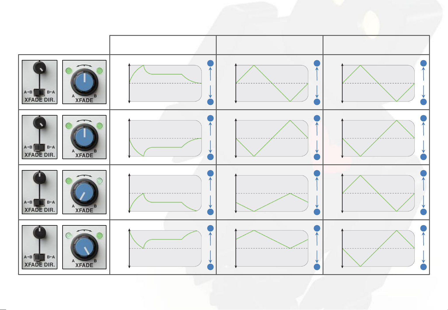
XFADE response - 01
UNIPOLAR signal input
[0V/+...V] ADSR illustration
+...V
0V
-...V
+...V
0V
-...V
+...V
0V
BIPOLAR signal input
[-...V/+...V ] triangle LFO illustration
+...V
B
1:1
A
B
1:1
A
B
1:1
0V
-...V
+...V
0V
-...V
+...V
0V
B
1:1
A
B
1:1
A
B
1:1
MANUAL set (no input)
[CCW/CW] knob illustration
CW
noon
CCW
CW
noon
CCW
CW
noon
B
1:1
A
A
1:1
B
B
1:1
-...V
+...V
0V
-...V
A
B
1:1
A
-...V
+...V
0V
-...V
A
B
1:1
A
CCW
CW
noon
CCW
A
A
1:1
B
11
Page 14
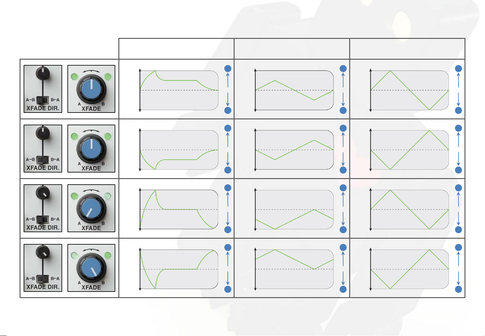
XFADE response - 02
UNIPOLAR signal input
[0V/+...V] ADSR illustration
+...V
0V
-...V
+...V
0V
-...V
+...V
0V
BIPOLAR signal input
[-...V/+...V ] triangle LFO illustration
+...V
B
1:1
A
B
1:1
A
B
1:1
0V
-...V
+...V
0V
-...V
+...V
0V
B
1:1
A
B
1:1
A
B
1:1
MANUAL set (no input)
[CCW/CW] knob illustration
CW
noon
CCW
CW
noon
CCW
CW
noon
B
1:1
A
A
1:1
B
B
1:1
-...V
+...V
0V
-...V
A
B
1:1
A
-...V
+...V
0V
-...V
A
B
1:1
A
CCW
CW
noon
CCW
A
A
1:1
B
12
Page 15
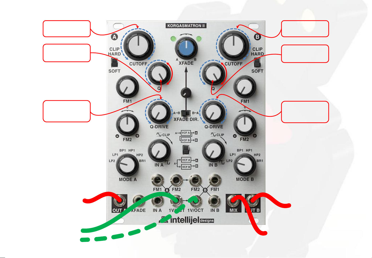
State-variable stereo filter
Set the Korgasmatron in PARALLEL configuration.
Use same LP-BP-HP-BR's switch position for A & B
filters to set type of stereo filter.
2-pole low-pass stereo filter for this illustration.
set stereo filter
type
same position
as filter B
filter A
LEFT out
LEFT signal
IN
set stereo filter
type
same position
as filter B
filter B
RIGHT out
RIGHT signal
IN
13
Page 16
State-variable stereo filter - VC pan patch
Requires 2 bipolar VCAs.
Set gain of VCA to +1 and VCA 2 to -1.
In this patch, a positive offset patched at VCA 1 CV
in & VCA 2 CV in down the amplitude of RIGHT out,
while up amplitude of LEFT out.
A negative offset patched at VCA 1 CV in & VCA 2
CV in up the amplitude of RIGHT out, while down
amplitude of LEFT out.
Use same LP-BP-HP-BR's switch position for A & B
filters to set type of stereo filter.
Low-pass stereo filter for this illustration.
set stereo filter
type
same position
as filter B
LEFT signal
RIGHT signal
IN
IN
set stereo filter
same position
as filter B
filter A
out
filter B
out
type
CV in
bipolar VCA 1
in / gain +1
bipolar VCA 2
in / gain -1
CV in
same CV
signal
LEFT
out
RIGHT
out
14
Page 17
1-pole BAND-PASS filter patch
CUTOFF/BANDWIDTH
set with
A low-pass
always > B high-pass
CV
CUTOFF/BANDWIDTH
CV
CUTOFF/BANDWIDTH
Monitoring band-pass filter at OUT B in SERIAL
configuration.
band-pass CUTOFF shift :
Manually set A & B cutoff, with A low-pass cutoff always
> B high-pass cutoff. Keep same relative knobs position
for cutoff shift.
OR/AND
Input same CV signal in A & B FM 1 with same attenuation
levels.
OR/AND
Use FM 2 normalled input and set FM 2 B as FM 2 A.
band-pass BANDWIDTH set :
Manually set A & B cutoff, with A low-pass cutoff always
> B high-pass cutoff. Keep different relative knobs
positions for bandwidth set.
OR/AND
Input different CV signals in A & B FM 1 with different
attenuation level.
OR/AND
Use FM 2 normalled input and set FM 2 B as inverted of
FM 2 A.
See band-pass filter chart for details on OUT B filter
curves.
signal to be
filtered
out
A B
freq.
band-pass filter out
15
Page 18
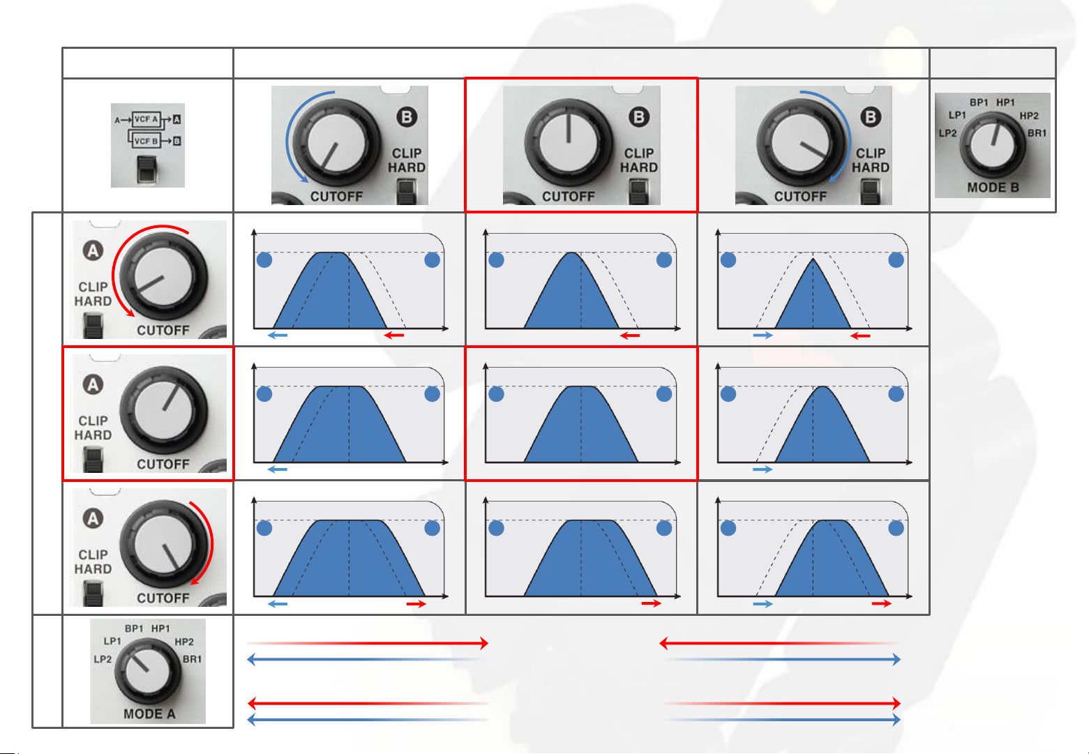
1-pole BAND-PASS filter curves
MIX
SERIAL - B OUT
B - HIGH-PASS 1-pole FILTER cutoff
out
A B A B
freq.
out
A B
out
out
A B
freq.
HP1 MODE
out
A B
freq.
out
A B
freq.
freq.
out
A B A B
out
freq.
out
A B
A -LOW-PASS 1-pole FILTER cutoff
freq.
filter BANDWIDTH
LP1 MODE
filter CUTOFF SHIFT
freq.
freq.
16
Page 19
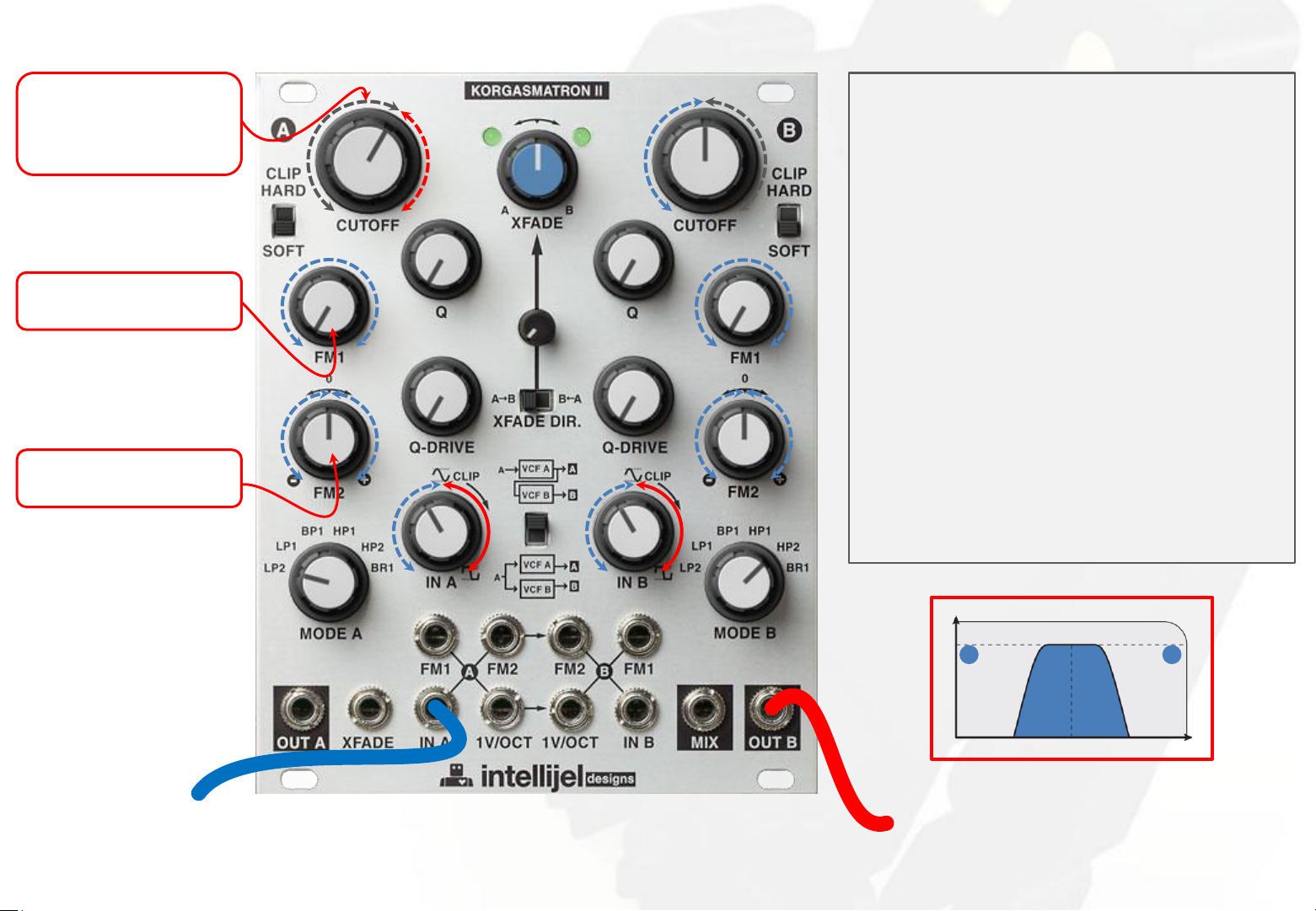
2-pole BAND-PASS filter patch
CUTOFF/BANDWIDTH
set with
A low-pass
always > B high-pass
CV
CUTOFF/BANDWIDTH
CV
CUTOFF/BANDWIDTH
Monitoring band-pass filter at OUT B in SERIAL
configuration.
band-pass CUTOFF shift :
Manually set A & B cutoff, with A low-pass cutoff always
> B high-pass cutoff. Keep same relative knobs position
for cutoff shift.
OR/AND
Input same CV signal in A & B FM 1 with same attenuation
levels.
OR/AND
Use FM 2 normalled input and set FM 2 B as FM 2 A.
band-pass BANDWIDTH set :
Manually set A & B cutoff, with A low-pass cutoff always
> B high-pass cutoff. Keep different relative knobs
positions for bandwidth set.
OR/AND
Input different CV signals in A & B FM 1 with different
attenuation level.
OR/AND
Use FM 2 normalled input and set FM 2 B as inverted of
FM 2 A.
See band-pass filter chart for details on OUT B filter
curves.
signal to be
filtered
out
A B
freq.
band-pass filter out
17
Page 20

2-pole BAND-PASS filter curves
MIX
SERIAL - B OUT
B - HIGH-PASS 2-pole FILTER cutoff
out
A B A B
freq.
out
A B
out
out
A B
freq.
HP2 MODE
out
A B
freq.
out
A B
freq.
freq.
out
A B A B
out
freq.
out
A B
A -LOW-PASS 2-pole FILTER cutoff
freq.
filter BANDWIDTH
LP2 MODE
filter CUTOFF SHIFT
freq.
freq.
18
Page 21

1-pole BAND-REJECT filter patch
CUTOFF/BANDWIDTH
set with
A low-pass
always < B high-pass
CV
CUTOFF/BANDWIDTH
CV
CUTOFF/BANDWIDTH
Monitoring band-reject filter at MIX in PARALLEL
configuration with 1:1 XFADE.
band-reject CUTOFF shift :
Manually set A & B cutoff, with A low-pass cutoff always
< B high-pass cutoff. Keep same relative knobs position
for cutoff shift.
OR/AND
Input same CV signal in A & B FM 1 with same attenuation
levels.
OR/AND
Use FM 2 normalled input and set FM 2 B as FM 2 A.
band-reject BANDWIDTH set :
Manually set A & B cutoff, with A low-pass cutoff always
< B high-pass cutoff. Keep different relative knobs
positions for bandwidth set.
OR/AND
Input different CV signals in A & B FM 1 with different
attenuation level.
OR/AND
Use FM 2 normalled input and set FM 2 B as inverted of
FM 2 A.
See band-reject filter chart for details on MIX out filter
curves.
signal to be
filtered
out
A B
freq.
band-reject filter out
19
Page 22

1-pole BAND-REJECT filter curves
MIX
PARALLEL - 1:1 MIX OUT
B - HIGH-PASS 1-pole FILTER cutoff
out
A B A B
freq.
out
A B
out
out
A B
freq.
HP1 MODE
out
A B
freq.
out
A B
freq.
freq.
out
A B A B
out
freq.
out
A B
A - LOW-PASS 1-pole FILTER cutoff
freq.
filter BANDWIDTH
LP1 MODE
filter CUTOFF SHIFT
freq.
freq.
20
Page 23

2-POLE band-reject filter patch
CUTOFF/BANDWIDTH
set with
A low-pass
always < B high-pass
CV
CUTOFF/BANDWIDTH
CV
CUTOFF/BANDWIDTH
Monitoring band-reject filter at MIX in PARALLEL
configuration with 1:1 XFADE.
band-reject CUTOFF shift :
Manually set A & B cutoff, with A low-pass cutoff always
< B high-pass cutoff. Keep same relative knobs position
for cutoff shift.
OR/AND
Input same CV signal in A & B FM 1 with same attenuation
levels.
OR/AND
Use FM 2 normalled input and set FM 2 B as FM 2 A.
band-reject BANDWIDTH set :
Manually set A & B cutoff, with A low-pass cutoff always
< B high-pass cutoff. Keep different relative knobs
positions for bandwidth set.
OR/AND
Input different CV signals in A & B FM 1 with different
attenuation level.
OR/AND
Use FM 2 normalled input and set FM 2 B as inverted of
FM 2 A.
See band-reject filter chart for details on MIX out filter
curves.
signal to be
filtered
out
A B
freq.
band-reject filter out
21
Page 24

2-pole BAND-REJECT filter curves
MIX
PARALLEL - 1:1 MIX OUT
B - HIGH-PASS 2-pole FILTER cutoff
out
A B A B
freq.
out
A B
out
out
A B
freq.
HP2 MODE
out
A B
freq.
out
A B
freq.
freq.
out
A B A B
out
freq.
out
A B
A - LOW-PASS 2-pole FILTER cutoff
freq.
filter BANDWIDTH
LP2 MODE
filter CUTOFF SHIFT
freq.
freq.
22
Page 25

Asymmetrical BAND-PASS filter patch
CUTOFF/BANDWIDTH
set with
A low-pass
always > B high-pass
CV
CUTOFF/BANDWIDTH
CV
CUTOFF/BANDWIDTH
Monitoring band-pass filter at OUT B in SERIAL
configuration.
band-pass CUTOFF shift :
Manually set A & B cutoff, with A low-pass cutoff always
> B high-pass cutoff. Keep same relative knobs position
for cutoff shift.
OR/AND
Input same CV signal in A & B FM 1 with same attenuation
levels.
OR/AND
Use FM 2 normalled input and set FM 2 B as FM 2 A.
band-pass BANDWIDTH set :
Manually set A & B cutoff, with A low-pass cutoff always
> B high-pass cutoff. Keep different relative knobs
positions for bandwidth set.
OR/AND
Input different CV signals in A & B FM 1 with different
attenuation level.
OR/AND
Use FM 2 normalled input and set FM 2 B as inverted of
FM 2 A.
See asymmetrical band-pass filter chart for details on
OUT B filter curves.
signal to be
filtered
out
A B
freq.
asymmetrical
band-pass filter
out
23
Page 26

Asymmetrical BAND-PASS filter curves
MIX
SERIAL - B OUT
B - HIGH-PASS 2-pole FILTER cutoff
out
A B A B
freq.
out
A B
out
out
A B
freq.
HP2 MODE
out
A B
freq.
out
A B
freq.
freq.
out
A B A B
out
freq.
out
A B
A -LOW-PASS 1-pole FILTER cutoff
freq.
filter BANDWIDTH
LP1 MODE
filter CUTOFF SHIFT
freq.
freq.
24
Page 27

Asymmetrical BAND-REJECT filter patch
CUTOFF/BANDWIDTH
set with
A low-pass
always < B high-pass
CV
CUTOFF/BANDWIDTH
CV
CUTOFF/BANDWIDTH
Monitoring band-reject filter at MIX in PARALLEL
configuration with 1:1 XFADE.
band-reject CUTOFF shift :
Manually set A & B cutoff, with A low-pass cutoff always
< B high-pass cutoff. Keep same relative knobs position
for cutoff shift.
OR/AND
Input same CV signal in A & B FM 1 with same attenuation
levels.
OR/AND
Use FM 2 normalled input and set FM 2 B as FM 2 A.
band-reject BANDWIDTH set :
Manually set A & B cutoff, with A low-pass cutoff always
< B high-pass cutoff. Keep different relative knobs
positions for bandwidth set.
OR/AND
Input different CV signals in A & B FM 1 with different
attenuation level.
OR/AND
Use FM 2 normalled input and set FM 2 B as inverted of
FM 2 A.
See asymmetrical band-reject filter chart for details on
MIX out filter curves.
signal to be
filtered
out
A B
freq.
asymmetrical
band-reject filter
out
25
Page 28

Asymmetrical BAND-REJECT filter curves
MIX
PARALLEL - 1:1 MIX OUT
B - HIGH-PASS 1-pole FILTER cutoff
out
A B A B
freq.
out
A B
out
out
A B
freq.
HP1 MODE
out
A B
freq.
out
A B
freq.
freq.
out
A B A B
out
freq.
out
A B
A - LOW-PASS 2-pole FILTER cutoff
freq.
filter BANDWIDTH
LP2 MODE
filter CUTOFF SHIFT
freq.
freq.
26
Page 29

Dual BAND-PASS filter patch
CUTOFF/BANDWIDTH
set with
A band-pass
always ≠ B band-pass
CV
CUTOFF/BANDWIDTH
CV
CUTOFF/BANDWIDTH
Monitoring dual band-pass filter at MIX in PARALLEL
configuration with 1:1 XFADE.
dual band-pass CUTOFF shift :
Manually set A & B cutoff, with A band-pass cutoff always
≠ B band-pass cutoff. Keep same relative knobs position
for cutoff shift.
OR/AND
Input same CV signal in A & B FM 1 with same attenuation
levels.
OR/AND
Use FM 2 normalled input and set FM 2 B as FM 2 A.
dual band-pass BANDWIDTH set :
Manually set A & B cutoff, with A band-pass cutoff always
≠ B band-pass cutoff. Keep different relative knobs
positions for banwidth set.
OR/AND
Input different CV signals in A & B FM 1 with different
attenuation level.
OR/AND
Use FM 2 normalled input and set FM 2 B as inverted of
FM 2 A.
See dual band-pass filter chart for details on MIX out
filter curves.
signal to be
filtered
out
A B
freq.
dual band-pass out
27
Page 30

Dual BAND-PASS filter curves
MIX
PARALLEL - 1:1 MIX OUT
B - BAND-PASS 1-pole FILTER cutoff
out
A B A B
freq.
out
A B
out
out
A B
freq.
BP1 MODE
out
A B
freq.
out
A B
freq.
freq.
out
A B A B
out
freq.
out
A B
A - BAND-PASS 1-pole FILTER cutoff
freq.
filter BANDWIDTH
BP1 MODE
filter CUTOFF SHIFT
freq.
freq.
28
Page 31

Dual BAND-REJECT filter patch
CUTOFF/BANDWIDTH
set with
A band-reject always
≠ B band-reject
CV
CUTOFF/BANDWIDTH
CV
CUTOFF/BANDWIDTH
Monitoring band-pass filter at OUT B in SERIAL
configuration.
dual band-reject CUTOFF shift :
Manually set A & B cutoff, with A band-reject cutoff
always ≠ B band-reject cutoff. Keep same relative knobs
position for cutoff shift.
OR/AND
Input same CV signal in A & B FM 1 with same attenuation
levels.
OR/AND
Use FM 2 normalled input and set FM 2 B as FM 2 A.
dual band-reject BANDWIDTH set :
Manually set A & B cutoff, with A band-reject cutoff
always ≠ B band-reject cutoff. Keep different relative
knobs positions for banwidth set.
OR/AND
Input different CV signals in A & B FM 1 with different
attenuation level.
OR/AND
Use FM 2 normalled input and set FM 2 B as inverted of
FM 2 A.
See dual band-reject filter chart for details on OUT B
filter curves.
signal to be
filtered
out
A B
freq.
dual band-reject out
29
Page 32

Dual BAND-REJECT filter curves
MIX
SERIAL - B OUT
B - BAND-REJECT 1-pole FILTER cutoff
out
A B A B
freq.
out
A B
out
out
A B
freq.
BR1 MODE
out
A B
freq.
out
A B
freq.
freq.
out
A B A B
out
freq.
out
A B
A - BAND-REJECT 1-pole FILTER cutoff
freq.
filter BANDWIDTH
BR1 MODE
filter CUTOFF SHIFT
freq.
freq.
30
Page 33

(BP1 + LP1) filter patch
CUTOFF/BANDWIDTH
set with
A low-pass
always < B band-pass
CV
CUTOFF/BANDWIDTH
CV
CUTOFF/BANDWIDTH
Monitoring (BP1 + LP1) filter at MIX in PARALLEL
configuration with 1:1 XFADE.
(BP1 + LP1) CUTOFF shift :
Manually set A & B cutoff, with A low-pass cutoff always
< B band-pass cutoff. Keep same relative knobs position
for cutoff shift.
OR/AND
Input same CV signal in A & B FM 1 with same attenuation
levels.
OR/AND
Use FM 2 normalled input and set FM 2 B as FM 2 A.
(BP1 + LP1) BANDWIDTH set :
Manually set A & B cutoff, with A low-pass cutoff always
< B band-pass cutoff. Keep different relative knobs
positions for bandwidth set.
OR/AND
Input different CV signals in A & B FM 1 with different
attenuation level.
OR/AND
Use FM 2 normalled input and set FM 2 B as inverted of
FM 2 A.
See (BP1 + LP1) filter chart for details on MIX out filter
curves.
signal to be
filtered
out
A B
freq.
(BP1 + LP1) out
31
Page 34

(BP1 + LP1) filter curves
MIX
PARALLEL - 1:1 MIX OUT
B - BAND-PASS 1-pole FILTER cutoff
out
A B A B
freq.
out
A B
out
out
A B
freq.
BP1 MODE
out
A B
freq.
out
A B
freq.
freq.
out
A B A B
out
freq.
out
A B
A - LOW-PASS 1-pole FILTER cutoff
freq.
filter BANDWIDTH
LP1 MODE
filter CUTOFF SHIFT
freq.
freq.
32
Page 35

(BP1 + LP2) filter patch
CUTOFF/BANDWIDTH
set with
A low-pass
always < B band-pass
CV
CUTOFF/BANDWIDTH
CV
CUTOFF/BANDWIDTH
Monitoring (BP1 + LP2) filter at MIX in PARALLEL
configuration with 1:1 XFADE.
(BP1 + LP2) CUTOFF shift :
Manually set A & B cutoff, with A low-pass cutoff always
< B band-pass cutoff. Keep same relative knobs position
for cutoff shift.
OR/AND
Input same CV signal in A & B FM 1 with same attenuation
levels.
OR/AND
Use FM 2 normalled input and set FM 2 B as FM 2 A.
(BP1 + LP2) BANDWIDTH set :
Manually set A & B cutoff, with A low-pass cutoff always
< B band-pass cutoff. Keep different relative knobs
positions for bandwidth set.
OR/AND
Input different CV signals in A & B FM 1 with different
attenuation level.
OR/AND
Use FM 2 normalled input and set FM 2 B as inverted of
FM 2 A.
See (BP1 + LP2) filter chart for details on MIX out filter
curves.
signal to be
filtered
out
A B
freq.
(BP1 + LP2) out
33
Page 36

(BP1 + LP2) filter curves
MIX
PARALLEL - 1:1 MIX OUT
B - BAND-PASS 1-pole FILTER cutoff
out
A B A B
freq.
out
A B
out
out
A B
freq.
BP1 MODE
out
A B
freq.
out
A B
freq.
freq.
out
A B A B
out
freq.
out
A B
A - LOW-PASS 2-pole FILTER cutoff
freq.
filter BANDWIDTH
LP2 MODE
filter CUTOFF SHIFT
freq.
freq.
34
Page 37

(BP1 + HP1) filter patch
CUTOFF/BANDWIDTH
set with
A band-pass
always < B high-pass
CV
CUTOFF/BANDWIDTH
CV
CUTOFF/BANDWIDTH
Monitoring (BP1 + HP1) filter at MIX in PARALLEL
configuration with 1:1 XFADE.
(BP1 + HP1) CUTOFF shift :
Manually set A & B cutoff, with A band-pass cutoff always
< B high-pass cutoff. Keep same relative knobs position
for cutoff shift.
OR/AND
Input same CV signal in A & B FM 1 with same attenuation
levels.
OR/AND
Use FM 2 normalled input and set FM 2 B as FM 2 A.
(BP1 + HP1) BANDWIDTH set :
Manually set A & B cutoff, with A band-pass cutoff always
< B high-pass cutoff. Keep different relative knobs
positions for bandwidth set.
OR/AND
Input different CV signals in A & B FM 1 with different
attenuation level.
OR/AND
Use FM 2 normalled input and set FM 2 B as inverted of
FM 2 A.
See (BP1 + HP1) filter chart for details on MIX out filter
curves.
signal to be
filtered
out
A B
freq.
(BP1 + HP1) out
35
Page 38

(BP1 + HP1) filter curves
MIX
PARALLEL - 1:1 MIX OUT
B - HIGH-PASS 1-pole FILTER cutoff
out
A B A B
freq.
out
A B
out
out
A B
freq.
HP1 MODE
out
A B
freq.
out
A B
freq.
freq.
out
A B A B
out
freq.
out
A B
A - BAND-PASS 1-pole FILTER cutoff
freq.
filter BANDWIDTH
BP1 MODE
filter CUTOFF SHIFT
freq.
freq.
36
Page 39

(BP1 + HP2) filter patch
CUTOFF/BANDWIDTH
set with
A band-pass
always < B high-pass
CV
CUTOFF/BANDWIDTH
CV
CUTOFF/BANDWIDTH
Monitoring (BP1 + HP2) filter at MIX in PARALLEL
configuration with 1:1 XFADE.
(BP1 + HP2) CUTOFF shift :
Manually set A & B cutoff, with A band-pass cutoff always
< B high-pass cutoff. Keep same relative knobs position
for cutoff shift.
OR/AND
Input same CV signal in A & B FM 1 with same attenuation
levels.
OR/AND
Use FM 2 normalled input and set FM 2 B as FM 2 A.
(BP1 + HP2) BANDWIDTH set :
Manually set A & B cutoff, with A band-pass cutoff always
< B high-pass cutoff. Keep different relative knobs
positions for bandwidth set.
OR/AND
Input different CV signals in A & B FM 1 with different
attenuation level.
OR/AND
Use FM 2 normalled input and set FM 2 B as inverted of
FM 2 A.
See (BP1 + HP2) filter chart for details on MIX out filter
curves.
signal to be
filtered
out
A B
freq.
(BP1 + HP1) out
37
Page 40

(BP1 + HP2) filter curves
MIX
PARALLEL - 1:1 MIX OUT
B - HIGH-PASS 1-pole FILTER cutoff
out
A B A B
freq.
out
A B
out
out
A B
freq.
HP2 MODE
out
A B
freq.
out
A B
freq.
freq.
out
A B A B
out
freq.
out
A B
A - BAND-PASS 1-pole FILTER cutoff
freq.
filter BANDWIDTH
BP1 MODE
filter CUTOFF SHIFT
freq.
freq.
38
Page 41

(BR1 + LP1) filter patch
CUTOFF/BANDWIDTH
set with
A band-reject
always < B low-pass
CV
CUTOFF/BANDWIDTH
CV
CUTOFF/BANDWIDTH
Monitoring (BR1 + LP1) filter at OUT B in SERIAL
configuration.
(BR1 + LP1) CUTOFF shift :
Manually set A & B cutoff, with A band-reject cutoff
always < B low-pass cutoff. Keep same relative knobs
position for cutoff shift.
OR/AND
Input same CV signal in A & B FM 1 with same attenuation
levels.
OR/AND
Use FM 2 normalled input and set FM 2 B as FM 2 A.
(BR1 + LP1) BANDWIDTH set :
Manually set A & B cutoff, with A band-reject cutoff
always < B low-pass cutoff. Keep different relative knobs
positions for bandwidth set.
OR/AND
Input different CV signals in A & B FM 1 with different
attenuation level.
OR/AND
Use FM 2 normalled input and set FM 2 B as inverted of
FM 2 A.
See (BR1 + LP1) filter chart for details on OUT B filter
curves.
signal to be
filtered
out
A B
freq.
(BR1 + LP1) out
39
Page 42

(BR1 + LP1) filter curves
MIX
SERIAL - B OUT
B - LOW-PASS 1-pole FILTER cutoff
out
A B A B
freq.
out
A B
out
out
A B
freq.
LP1 MODE
out
A B
freq.
out
A B
freq.
freq.
out
A B A B
out
freq.
out
A B
A -BAND-REJECT 1-pole FILTER cutoff
freq.
filter BANDWIDTH
BR1 MODE
filter CUTOFF SHIFT
freq.
freq.
40
Page 43

(BR1 + LP2) filter patch
CUTOFF/BANDWIDTH
set with
A band-reject
always < B low-pass
CV
CUTOFF/BANDWIDTH
CV
CUTOFF/BANDWIDTH
Monitoring (BR1 + LP2) filter at OUT B in SERIAL
configuration.
(BR1 + LP2) CUTOFF shift :
Manually set A & B cutoff, with A band-reject cutoff
always < B low-pass cutoff. Keep same relative knobs
position for cutoff shift.
OR/AND
Input same CV signal in A & B FM 1 with same attenuation
levels.
OR/AND
Use FM 2 normalled input and set FM 2 B as FM 2 A.
(BR1 + LP2) BANDWIDTH set :
Manually set A & B cutoff, with A band-reject cutoff
always < B low-pass cutoff. Keep different relative knobs
positions for bandwidth set.
OR/AND
Input different CV signals in A & B FM 1 with different
attenuation level.
OR/AND
Use FM 2 normalled input and set FM 2 B as inverted of
FM 2 A.
See (BR1 + LP2) filter chart for details on OUT B filter
curves.
signal to be
filtered
out
A B
freq.
(BR1 + LP2) out
41
Page 44

(BR1 + LP2) filter curves
MIX
SERIAL - B OUT
B - LOW-PASS 2-pole FILTER cutoff
out
A B A B
freq.
out
A B
out
out
A B
freq.
LP2 MODE
out
A B
freq.
out
A B
freq.
freq.
out
A B A B
out
freq.
out
A B
A -BAND-REJECT 1-pole FILTER cutoff
freq.
filter BANDWIDTH
BR1 MODE
filter CUTOFF SHIFT
freq.
freq.
42
Page 45

(BR1 + HP1) filter patch
CUTOFF/BANDWIDTH
set with
A high-pass always
< B band-reject
CV
CUTOFF/BANDWIDTH
CV
CUTOFF/BANDWIDTH
Monitoring (BR1 + HP1) filter at OUT B in SERIAL
configuration.
(BR1 + HP1) CUTOFF shift :
Manually set A & B cutoff, with A high-pass cutoff always
< B band-reject cutoff. Keep same relative knobs position
for cutoff shift.
OR/AND
Input same CV signal in A & B FM 1 with same attenuation
levels.
OR/AND
Use FM 2 normalled input and set FM 2 B as FM 2 A.
(BR1 + HP1) BANDWIDTH set :
Manually set A & B cutoff, with A high-pass cutoff always
< B band-reject cutoff. Keep different relative knobs
positions for bandwidth set.
OR/AND
Input different CV signals in A & B FM 1 with different
attenuation level.
OR/AND
Use FM 2 normalled input and set FM 2 B as inverted of
FM 2 A.
See (BR1 + HP1) filter chart for details on OUT B filter
curves.
signal to be
filtered
out
A B
freq.
(BR1 + HP1) out
43
Page 46

(BR1 + HP1) filter curves
MIX
SERIAL - B OUT
B - BAND-REJECT 1-pole FILTER cutoff
out
A B A B
freq.
out
A B
out
out
A B
freq.
BR1 MODE
out
A B
freq.
out
A B
freq.
freq.
out
A B A B
out
freq.
out
A B
A - HIGH-PASS 1-pole FILTER cutoff
freq.
filter BANDWIDTH
HP1 MODE
filter CUTOFF SHIFT
freq.
freq.
44
Page 47

(BR1 + HP2) filter patch
CUTOFF/BANDWIDTH
set with
A high-pass always
< B band-reject
CV
CUTOFF/BANDWIDTH
CV
CUTOFF/BANDWIDTH
Monitoring (BR1 + HP2) filter at OUT B in SERIAL
configuration.
(BR1 + HP2) CUTOFF shift :
Manually set A & B cutoff, with A high-pass cutoff always
< B band-reject cutoff. Keep same relative knobs position
for cutoff shift.
OR/AND
Input same CV signal in A & B FM 1 with same attenuation
levels.
OR/AND
Use FM 2 normalled input and set FM 2 B as FM 2 A.
(BR1 + HP2) BANDWIDTH set :
Manually set A & B cutoff, with A high-pass cutoff always
< B band-reject cutoff. Keep different relative knobs
positions for bandwidth set.
OR/AND
Input different CV signals in A & B FM 1 with different
attenuation level.
OR/AND
Use FM 2 normalled input and set FM 2 B as inverted of
FM 2 A.
See (BR1 + HP2) filter chart for details on OUT B filter
curves.
signal to be
filtered
out
A B
freq.
(BR1 + HP1) out
45
Page 48

(BR1 + HP2) filter curves
MIX
SERIAL - B OUT
B - BAND-REJECT 1-pole FILTER cutoff
out
A B A B
freq.
out
A B
out
out
A B
freq.
BR1 MODE
out
A B
freq.
out
A B
freq.
freq.
out
A B A B
out
freq.
out
A B
A - HIGH-PASS 2-pole FILTER cutoff
freq.
filter BANDWIDTH
HP2 MODE
filter CUTOFF SHIFT
freq.
freq.
46
Page 49

set bass
frequency
make filter A
self-oscillate
set past 12
o'clock for
heavy bass
Heavy dub bass
filter A bass
out
bassline CV
47
Page 50

set ping
frequency
set just under
filter A self-
oscillation
Ping !
out
filter A ping
out
time
short A/D or trigger
in A
48
Page 51

Weird filter
XFADE position
attenuator
for
XFADE
input
XFADE
signal input
Advice : If you are using the
Korgasmatron II in SERIAL
configuration inserting a plug into IN
B jack will break the internal routing
from filter A which may cause
confusion.
signal to be
filtered
!
weird filter out
49
Page 52

Spacewave sound
+...V
0V
-...V
set filter A coarse
frequency
make filter A
self-oscillate
XFADE input
attenuator
set filter B coarse
frequency
slightly detuned with
filter A
make filter B
self-oscillate
B
1:1
A
sub-audio
bipolar
XFADE signal
input
1V/Oct
quantized CV
spacewave sound out
50
Page 53

make filter A
self-oscillate
Feedback loop
Monitoring MIX output in SERIAL
configuration.
feedback loop out
51
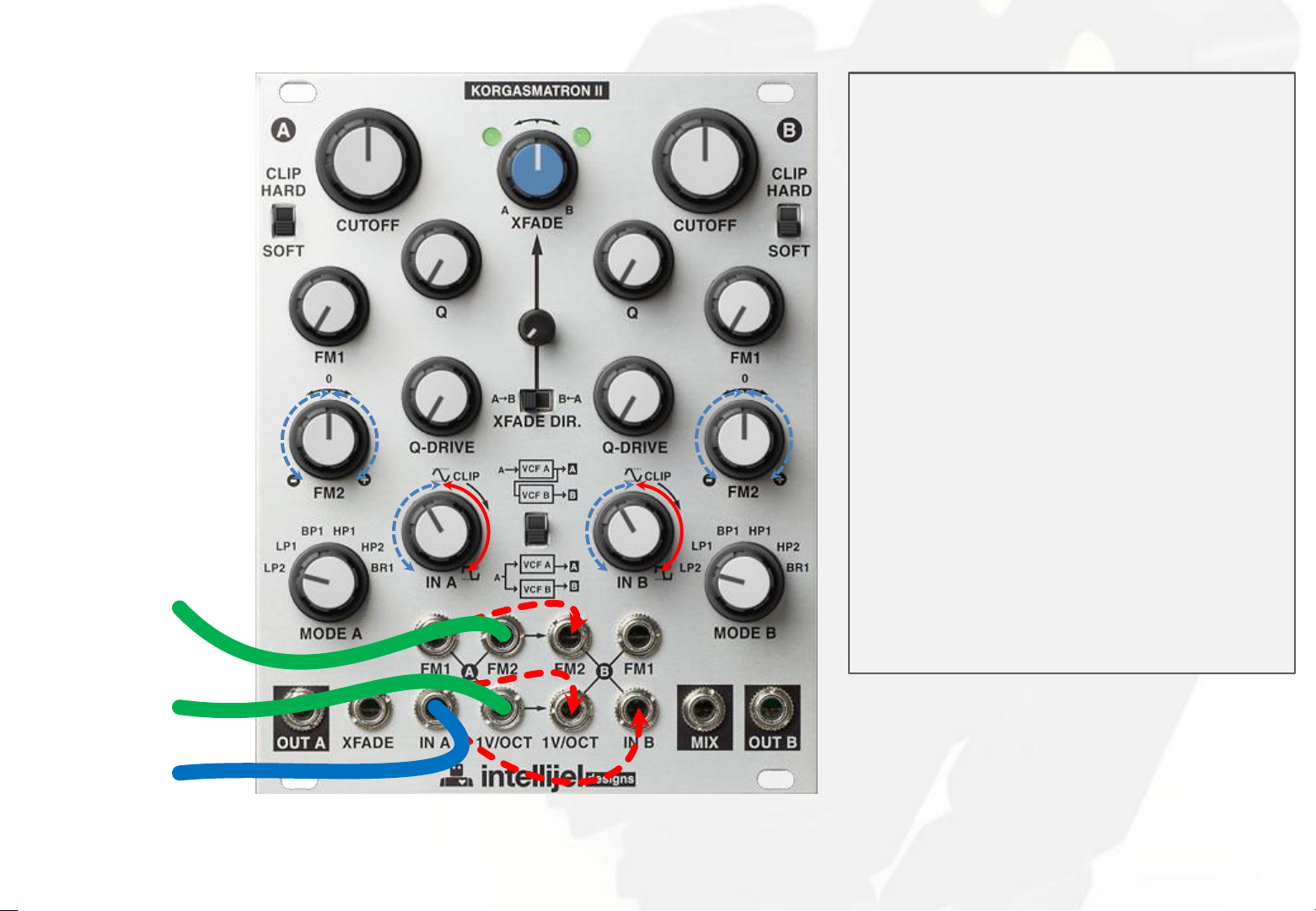
Page 54

Cross-FM
Monitoring MIX output in PARALLEL
configuration.
make filter A
self-oscillate
make filter B
self-oscillate
cross-FM out
52
Page 55

Feedback cross-FM
Monitoring MIX output in SERIAL
configuration.
make filter A
self-oscillate
make filter B
self-oscillate
feedback cross-FM out
53
Page 56

Drone zone 1
Monitoring OUT B or MIX output in SERIAL
configuration.
Set filter B FM2 opposite to filter A
FM2.
Experiment with different cutoff, Q and Q-DRIVE
values for both filters.
OUT B for +V FM2 input CV :
out
+...V
0V
-...V
slow bipolar
FM2 signal
input
A B
freq.
OUT B for -V FM2 input CV :
out
A B
freq.
drone zone out
serial MIX out triangle in
54
Page 57

set AUX MOD A
AUX IN A level
Q CV A level
set AUX MOD B
AUX IN B level
Expander - Overview
Q CV B level
55
Page 58

Q CV A level
Expander - VC Q filtering
Q CV B level
Q CV signal
filter A out
filter B out
signal in
MIX out
56
Page 59

AUX IN A level
AUX IN B level
Expander - Quad filter
AUX A signal
in
AUX B signal
in
(AUX A + A)
out
A signal
in
B signal
in
(AUX B + B)
out
(AUX A + A) : (AUX B + B)
out
57
Page 60

AUX IN A level
AUX IN B level
Expander - Quad filter feedback loop
Monitoring MIX output in
SERIAL configuration.
make filter A
self-oscillate
feedback loop
out
58
Page 61

Q CV A level
Expander - Cross-Q modulation
Monitoring MIX output in
PARALLEL configuration.
make filters A &
B self-oscillate
Q CV B level
cross-Q out
59
Page 62

Q CV A level
Expander - Feedback cross-Q modulation
Monitoring MIX output in
SERIAL configuration.
make filters A &
B self-oscillate
Q CV B level
feedback
cross-Q out
60
Page 63

AUX IN A level
Expander - Drone zone 2
Monitoring OUT B or MIX output in
SERIAL configuration.
Set filter B FM2 opposite to filter A
FM2.
Experiment with different cutoff, Q and
Q-DRIVE values for both filters.
B OUT :
out
A B
freq.
B OUT for +V FM2 input CV :
out
AUX IN B level
triangle in
slow bipolar
FM2 signal
input
serial
MIX out
A B
freq.
B OUT for -V FM2 input CV :
out
A B
freq.
drone zone
out
61
 Loading...