

Page 1
HexVCA Manual v1.0
The HexVCA contains six separate DC coupled logarithmic VCAs that have their outputs
normalled to two outputs. The front panel outputs of each VCA is a switching jack which
breaks the normal to the mix out when it is patched. This design allows the HexVCA to be used
as 6 individual VCAs, a 6 input voltage controlled mixer or any combination e.g. 2 patched
VCAs and a four input VC mixer.
At the rear of the HexVCA You will find a six pin header that carries the outputs of the six
VCAs. This can be used to normal the outputs of the HexVCA to the Intellijel Mutagen mixer.
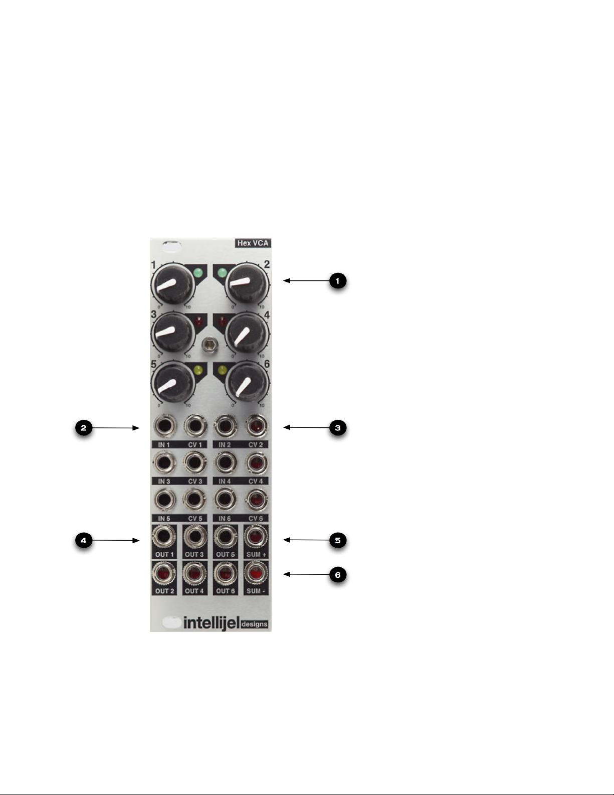
Front Panel
1 - VCA Offset
CV offset, also referred to as bias
knob. CV indicator LED.
2 - IN 1-6
The signal input of the VCAs.
3 - CV 1-6
The control inputs of the VCAs.
4 - Out 1-6
The output of the individual VCAs.
5 - SUM+
The output of the VCAs mixed
together.
6 - SUMThis is the same as SUM+ except it
has inverted phase.
Page 1 of 9
Page 2
HexVCA Manual v1.0
Front Panel Controls in Depth
1 - VCA offset/bias knob and CV indicator LED.
The knob offsets the level of the VCA by injecting 0-5v in to the CV input. This opens the VCA
and acts as an initial level control. For traditional VCA operation this knob should be left at 0
(fully counter clock wise).
2 - IN 1-6
The signal input of the VCAs. Patch audio or CV signals here to be controlled by the VCAs. In
a traditional VCA patch you would patch the output of your filter here.
3 - CV 1-6
The control inputs of the VCAs. Control voltage or audio rate signals patched here will control
the level of the VCA. In traditional VCA use you would patch the output of a envelope
generator here.
4 - Out 1-6
The output of the individual VCAs. Patching into these outputs will remove its VCA from the
SUM out.
5 - SUM+
The output of the VCAs mixed together. All of the VCAs are mixed together and output here. If
using the HexVCA as a mixer this is your output. Patching into the VCA individual outputs will
remove VCAs from this mix.
6 - SUMThis is the same as SUM+ except it has inverted phase. This is useful when constructing feed
back patches. Since the signal is inverted from SUM+ mixing it with SUM- will result in no
signal as the two waves will cancel each other out.
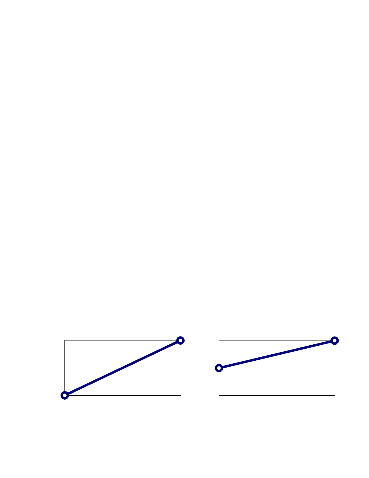
VCA Offset Explained
Offset at 0%
0
0
Offset at 50%
-80
0V 5V
-80
0V 5V
The above charts illustrates the effect the Offset knobs have on incoming CV. As offset is
increased the point at which 0 CV = -XdB is shifted upwards.
Page 2 of 9
Page 3
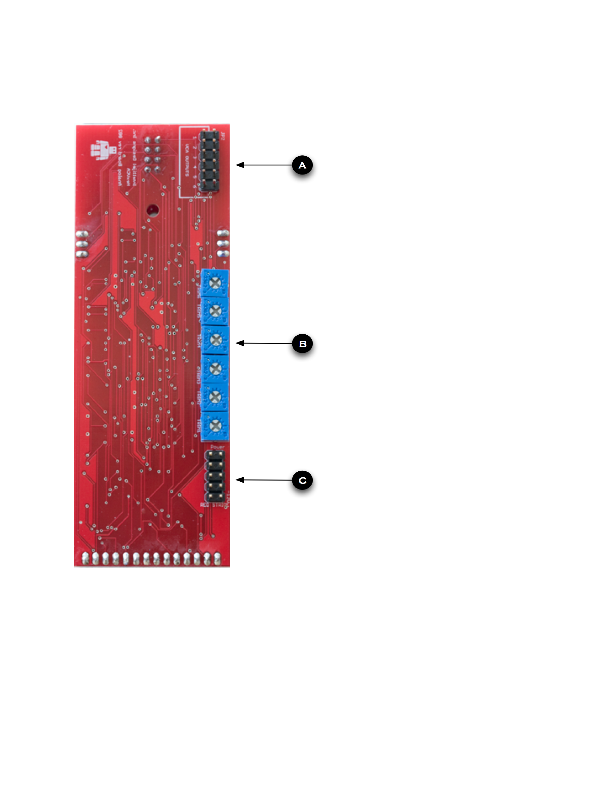
Rear Panel
HexVCA Manual v1.0
A - VCA output expander
This is a twelve pin header for connecting
to the Mutagen. This is the output of the six
individual VCAs
B - CV input trims.
These trimmers are attenuators for the CV
inputs. The reduce the CV level before it
reaches the VCA. Because CV levels vary
widely in modular synthesizers these may
need to be adjusted to get optimum
performance from your HexVCA.
Turning the trimmer counter clock wise will
reduce the CV level.
The HexVCA is designed to give 80db of
dynamic range for a 0-5v control signal.
Before leaving Intellijel these trims are
adjusted so that 5v in equals unity gain on
the VCA. If your CV input exceeds 5v there
is a small amount of gain. Depending on
the signal coming into the HexVCA IN this
may distort the VCA.
C - Power connector.
Ten pin power connector which conforms to
the Eurorack standard.
The lowest pin is -12V and should line up
with the red pin on your power ribbon.
It is very important that the power
connector is not connected in reverse!
Although no damage will be done to the
! ! ! ! ! ! ! HexVCA other modules may be damaged
! ! ! ! ! ! ! by reversing this connector.
Page 3 of 9
Page 4

HexVCA Manual v1.0
Block diagram 1 - VCA Detail
In the below diagram the internal signal flow of the HexVCA is shown. This diagram is
simplified to save space. Only one of the 6 VCAs is detailed.
Block diagram 2 - Overview
The diagram to the right
shows the signal flow of
the entire module.
Keep in mind all of the
Out jacks (shown as a
hexagon) are switching
jacks that break the
connection to the mixer
when a 3.5mm plug is
inserted.
Page 4 of 9
Page 5

HexVCA Manual v1.0
Patch Examples
Example 1 - Traditional synthesizer voice
In this example VCA 1 in the HexVCA is used to control the final level of a traditional
synthesizer voice. The output of the VCO goes into the VCF, the out put of the VCF goes into
the IN 1 of the HexVCA. Knob 1 of the HexVCA should be fully counter clock wise. The gate
out of the keyboard goes into the gate in of a ADSR. The output of the ADSR goes to the CV
1 input of the HexVCA. Out 1 of the HexVCA goes to your mixer, audio interface or
monitoring system.
If the keyboard is not played no sound will pass and the patch will be silent. If a key is played
on the keyboard the ADSR will rise in voltage causing a corresponding rise in volume from
the HexVCA. Once the key is released on the keyboard the ADSR voltage will fall to zero
and the HexVCA will fade to silence.
Page 5 of 9
Page 6

Patch Examples
Example 2 - Tremolo effect
HexVCA Manual v1.0
This patch demonstrates the common effect known as tremolo. A slow LFO modulates a VCA
creating a steady pulsing volume. This effect is sometimes found in old guitar amps and combo
organs.
In the Voice section on the left we have the traditional voice patch as seen in example 1.
In the Effect section on the right of the diagram is the Tremolo effect patch.
NOTE: Make sure you turn the Offset knob of HexVCA ch2 to 12 o clock. This opens the VCA
half way which is necessary when using bipolar modulation.
Use a sine wave for the LFO shape and a slow speed to for the traditional Tremolo sound.
Using higher speeds for the LFO and different waves will create harsher and more modern
sounds. You can substitute the LFO with a Envelope triggered in time to the music to create
rhythmic gating. In this case the Offset knob will control how much the VCA stays open, adjust
to taste.
Page 6 of 9
Page 7

HexVCA Manual v1.0
Patch Examples
Example 3 - Audio rate modulation / AM synthesis
This patch can produce a wide variety of metallic, sharp and pitched noise sounds.
NOTE: Make sure you turn the Offset knob of HexVCA ch1 to 12 o clock. This opens the VCA
half way which is necessary when using bipolar modulation such as a VCO or LFO.
The HexVCA creates sidebands by modulating the volume of a VCO 1 with VCO 2. These
sidebands can be harmonically related to VCO 1 if VCO 2 also tracks the keyboard and is set
to a even frequency ratio such as 4:1. If the frequency between the VCOs is not even
enharmonic sidebands are created. This is similar to ring modulation except that the original
signal (VCO 1) is still present. By modulating the frequency of VCO 2 with a LFO we get
moving sidebands that alters the timbre.
Experiment with different waves for the two VCOs and various frequencies between VCO 1
and 2. By altering the tracking of VCO 2 with an attenuator enharmonic and noise like sounds
are possible.
Try replacing VCO 1 with external audio such as drum patterns or polyphonic melodies.
Page 7 of 9
Page 8

HexVCA Manual v1.0
Patch Examples
Example 4 - Voltage Controlled Mixer
In this patch the HexVCA is used as a voltage controlled Mixer. Use the VCA Offset knobs on
the HexVCA to set the initial level of the various inputs. The CV inputs will be added to the
initial level set by the offset knobs. Positive CV will make the signal louder while negative CV
will make the signal quieter. Try tuning the VCOs to different octaves and using clock dividers
to trigger the ADs.
Page 8 of 9
Page 9

HexVCA Manual v1.0
Video Manual
http://vimeo.com/20822864
Follow the above link for a walk through of the HexVCA functions.
Support
Web:! http://intellijel.com/
email:!danjel@intellijel.com
Technical Specifications
Width:!! ! 8 HP
Depth:!! ! 35mm
Current Draw:! 80ma
Dynamic Range:! -80dB to 0dB! with 0-5v control signal
Expected input:! 5v peak to peak
VCA component: ! THATcorp 2162
Credits
HexVCA design: Danjel van Tjin
Manual written by: Haven Siguenza, Danjel van Tjin
Copyright 2011 Intellijel Designs Inc.
Made in Canada
Page 9 of 9
 Loading...