

Page 1
Corgasmatron Manual v1.0
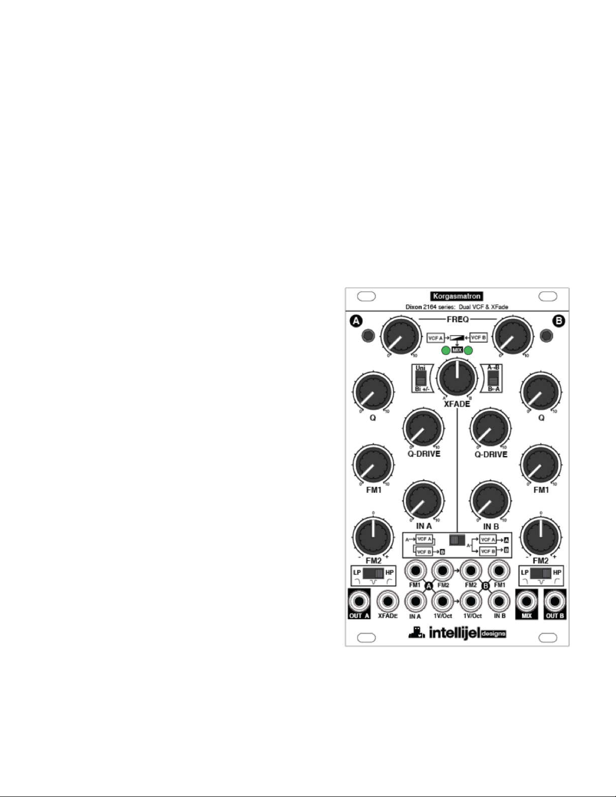
The Corgasmatron is a two independent multi mode filters and a cross fader mounted behind a
16HP Eurorack panel. The Corgasmatron's sound can range from ultra clean and precise, to
extremely ballsy and dirty.The resonance is incredibly musical and interesting and is prime for
all sorts of experimenting and sound design. The normalling, routing and cv options have been
carefully selected to allow for a lot of control over the modules functionality and capabilities.
The original circuit was designed by analog guru david g. dixon after carefully studying and
analyzing the classic korg ms-20 filter. His work resulted in a completely original circuit based
around ssm2164 vca chips. This design is capable of almost identical results but is far more
versatile. This is not a clone, it is an entirely new and modern circuit with many enhancements.
Key features:
16HP and shallow (two pcbs in parallel so it is
•
skiff friendly)
two independent filters, each with LP, HP and
•
Notch modes.
Unique resonant (Q) drive control
•
A Switch links the two filters allowing both
•
parallel and serial routing via normals to input B
(which can be broken by inserting a cable at
input B).
Oscillates very easily and can be used as a
•
dual sine VCO. Using the resonance controls
this Sine shape can be colored.
1V/Oct inputs for each filter
•
Built in full featured cross fader allows voltage
•
controlled xfading between the two filters. The
Xfade has a switch to select either unipolar
(e.g. envelopes) or bipolar (e.g. lfo) control of
the xfade position. There is also a switch to
select direction. With nothing plugged into the
Xfade jack the xfade knob controls the fade
position. When an external CV is patched in the
same knob acts as an attenuator for the control
signal.
Jumpers on the back to select "modern" or
•
"vintage" resonant modes (two different
feedback paths for the resonance that use
different diodes)
Expansion jacks for adding additional filter
•
inputs and VC control of resonance
Page 1 of 10
Page 2
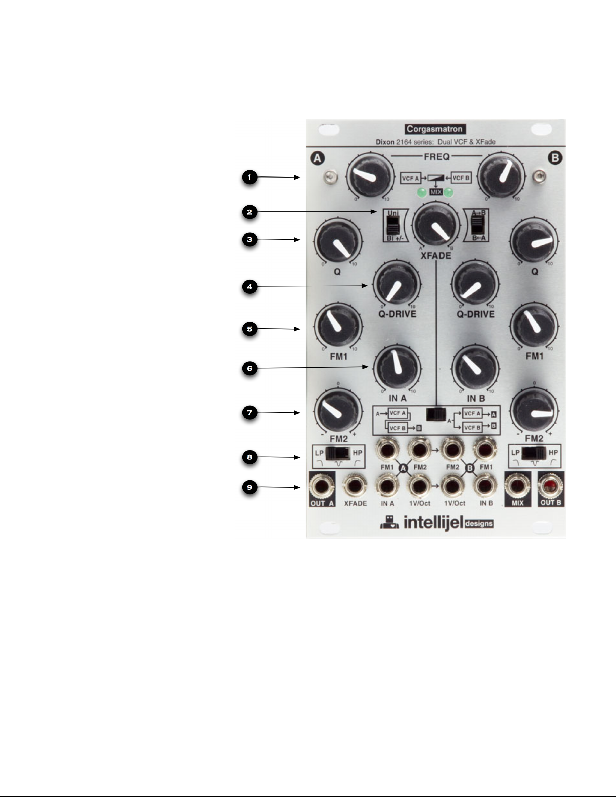
Front Panel
1- FREQ - Cutoff frequency of
the filter. This sets the center
frequency of the filter.
2- Xfader section. XFADE
position knob, CV polarity
switch and Xfade direction
switch. The Xfade knob acts
as cross fader in Parallel
configuration and using MIX
out if nothing is plugged into
the Xfade jack. Once patched
the Xfade knob becomes a
CV attenuator.
3- Q is also referred to as
resonance. Depending on
input gain moving this knob
past 1 oʼclock will cause the
filter to start oscillating.
Corgasmatron Manual v1.0
4- Q-DRIVE - is the level of
the resonance. This control is
also used to alter the timbre
of the resonant sound if the
filter is self oscillating.
5- FM1 - Unipolar attenuator
for FM1 input.
6- IN A - Input attenuator controls the level into the filter. For classic tone keep this below 12
oʼclock. Higher gain will suppress the resonance of the filter and change its tone. The
combination of IN A level, Q and Q Drive knobs can alter the tone of the filter dramatically
from sweet to scathing - experiment!
7- FM2 - Bi-polar attenuator for FM2 input. This is a center detent knob. Turning the knob
CCW will apply inverted CV, turning the knob CW will apply positive CV.
8- Filter mode switch. The three modes are 1 pole High Pass, 1 pole Notch, 2 pole Low Pass
9- Input and output jacks. Outputs are surrounded by a black outline.
Page 2 of 10
Page 3

FM1 A
CV input to VCF A filter cutoff, attenuated by FM1 A knob
FM2 A
CV input to VCF A filter cutoff, attenuated with inversion by FM2 A knob.
Normalled to VCF B FM2.
FM2 B
CV input to VCF B filter cutoff, attenuated with inversion by FM2 B knob. This
is a switching jack, inserting a plug here will break the normal from FM2 A.
Using this normal allows the same CV source patched into FM2 A to control
both filters. The bi polar attenuators can set opposite so as to lower the
frequency of one filter while raising the frequency of the other.
FM1 B
CV input to VCF B filter cutoff, attenuated by FM1 B knob
OUT A
Output of filter A
XFADE
CV input to Xfade section. This is a switching jack, when a plug is inserted
the XFADE knob becomes a CV attenuator. The Uni/Bi switch to the left of
the XFADE knob determines if this input is Unipolar or Bipolar. If using a
Envelope as a modulation source use Uni, If using. a LFO as a modulation
source use Bi.
IN A
Signal input to filter A. Patch a audio signal here to be filtered. The knob IN A
attenuates this signal. The input signal level alters the tone of the filter circuit
and the resonance behavior. For classic filter tone set the IN A knob to 11
oʼclock when using standard level modular VCOs.
1V/Oct A
CV input for filter frequency calibrated for 1V/oct standard. By patching the
1V/Oct output of your keyboard or MIDI to CV converter here the filter will
track the keyboard. This is normalled to the 1V/Oct CV input of filter B.
1V/Oct B
CV input for filter frequency calibrated for 1V/oct standard. This is switching
jack, inserting a plug here will break the normal from 1V/Oct A.
IN B
Signal input to filter B. Patch a audio signal here to be filtered. The knob IN B
attenuates this signal. See IN A for more detail. If you are using the
Corgasmatron in Serial configuration inserting a plug into this jack will break
the internal routing from filter A which may cause confusion.
MIX
Output of filter A and B mixed together. Use this output if the Corgasmatron is
in Parallel configuration and you want to mix the filters together to one
output.
OUT B
Output of filter B. In Series configuration use this output.
Corgasmatron Manual v1.0
Input and Output jacks (left to right top to bottom)
Page 3 of 10
Page 4

Rear Panel
Corgasmatron Manual v1.0
1 - XFade Adj. This trimmer adjusts the blend between channel A and channel B of the xfader.
To adjust make filter A resonate at 1 Khz, set routing configuration to parallel and monitor out
the MIX out. Turn the Xfade front panel knob fully CW so as to only pass filter B. Now adjust
the trimmer slowly until the filter A is no longer heard. This is calibrated at the factory.
2 - jumper, Q behavior selection filter B. This jumper selects different diodes for the Q circuit.
1-2 is Modern mode, 2-3 is Vintage mode.
Page 4 of 10
Page 5

Corgasmatron Manual v1.0
3 - Power connector. Ten pin power connector which conforms to the Eurorack standard. -12V
on the board must be connected to -12V on your bus board. -12V is commonly referred to as
the red stripe.
It is very important that the power connector is not connected in reverse! Although no
damage will be done to the Corgasmatron other modules may be damaged by reversing this
connector.
4 - Expansion header for filter B. A VCA inserted between the pins labeled Q will enable VC
control over Q.
5 - 1V/oct Adjustment of filter A and B. Although these are calibrated at the factory vibrations
during shipping, variance between power supply voltages and component tolerances changing
over time can cause the filter to move out of tune. Use this trimmers to calibrate the 1V/oct
response of the filter if you need to. See page 6 for the tuning procedure.
6 - 2 - jumper, Q behavior selection filter B. See 2 on the previous page for more information.
7 - Expansion header for filter B. See 4 for more information.
Page 5 of 10
Page 6

Corgasmatron Manual v1.0
1V/Oct calibration procedure:
The Corgasmatron is capable of being tuned to track 1V/Oct over a range of about
three to four octaves. You can tune the tracking using the dedicated 1V/Oct trimmers on
the back of the pcb. The calibration can be done by ear or using a frequency meter.
All you need is a voltage source capable of playing octave intervals (e.g. midi keyboard
+ cv converter).
Filter A:
1. Turn Q to max, Q Drive to zero and then adjust Freq to the base note you would like
to use (i.e the lowest note you plan to play).
2. Plug your CV source capable of playing 1 Octave intervals (i.e. 1V increments) into
the left "1V/Oct" jack.
3. Plug your frequency meter into Out A or use headphones/speakers to listen to the
output if tuning by ear.
4. Make note of your base frequency and then using your CV source increase it by one
octave. If the new octave is sharp relative to the base note then adjust the trim pot to
make the note sharper (note this may be counterintuitive). If the new octave is flat
relative to the base note then adjust the trim pot to make the new note flatter.
5. Repeat step 4, alternating between two intervals until it sounds in tune (or the
frequency meter is showing a close to perfect doubling of the frequency between the
base note and the first interval).
Filter B:
Follow the same procedure but monitor Out B instead.
NOTE: make sure the SERIES/PARALLEL switch is set to "PARALLEL" so that none of
Filter A is influencing the tuning.
Page 6 of 10
Page 7
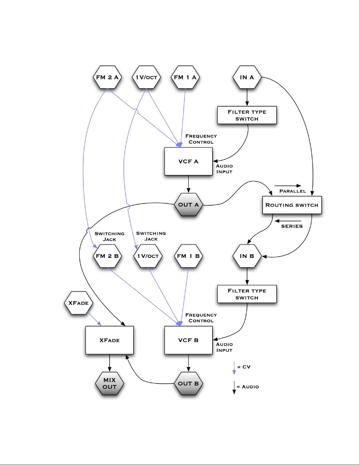
Corgasmatron block diagram
Corgasmatron Manual v1.0
Page 7 of 10
Page 8

Corgasmatron Manual v1.0
Patch Examples
Example 1 - Classic Style Variable Band Pass Filter
This patch shows the most common dual filter mono synthesizer patch. High pass VCF
goes into low pass VCF providing a variable width band pass filter. Use normals on the
1v/oct A and FM2 A CV inputs to control both filters at once,
Instructions
Set the Corgasmatron to Serial mode. Audio input goes into IN A. Audio output comes
from MIX. Patch according to the chart above to create the classic VCO-VCF-VCA voice.
Tips
-Patching a CV controller such as a joystick into FM2 A and setting both FM2 knobs to the
same setting will enable you to control both filter cutoffs simultaneously.
-Use FM1 inputs for both filters for different modulation, such as velocity to VCF B.
-Use the Q on VCF A to give a bass boost. Adjust the FREQ knob while playing you
keyboard until the filter begins to boost desired frequencies. The filter will track the notes
on your keyboard if the 1v/oct input is patched to your keyboard 1v/oct CV out.
Page 8 of 10
Page 9

Corgasmatron Manual v1.0
Video Manual
http://vimeo.com/26173568
Follow the above link for a walk through of the Corgasmatron functions.
Support
Web:" http://intellijel.com/
email:"support@intellijel.com
Technical Specifications
Width:"" " 16 HP
Depth:"" " 35mm
Current Draw:" +12v@ 70ma, -12v@ 67ma
Expected input:" 5v peak to peak
OTA component: " Cool Audio SSM2164
Credits
Original Corgasmatron design: David Dixon
Eurorack conversion, PCB design and realization: Danjel van Tjin
Manual written by: Haven Siguenza, Danjel van Tjin, David Dixon
Copyright 2011 Intellijel Designs Inc.
Page 9 of 10
Page 10

Made in Canada
Corgasmatron Manual v1.0
Page 10 of 10
 Loading...