

Page 1

Intel® Integrated RAID Controller
SRCS14L
Four-port Low Profile Serial ATA RAID Controller
Technical Product Specification, Version 1.0
November 2002
Order Number: 251526-001
Page 2

Technical Product Specification
Information in this document is provided in connection with Intel® products. No license, express or implied, by estoppel or otherwise, to any intellectual
property rights is granted by this document. Except as provided in Intel's Terms and Conditions of Sale for such products, Intel assumes no liability
whatsoever, and Intel disclaims any express or implied warranty, relating to sale and/or use of Intel products including liability or warranties relating to
fitness for a particular purpose, merchantability, or infringement of any patent, copyright or other intellectual property right. Intel products are not
intended for use in medical, life saving, or life sustaining applications.
Intel may make changes to specifications and product descriptions at any time, without notice.
The Intel SRCS14L RAID controller may contain design defects or errors known as errata which may cause the product to deviate from published
specifications. Current characterized errata are available on request.
Contact your local Intel sales office or your distributor to obtain the latest specifications and before placing your product order.
Copies of documents which have an ordering number and are referenced in this document, or other Intel literature may be obtained by calling
1-800-548-4725 or by visiting Intel's website at http://www.intel.com.
Copyright © Intel Corporation, 2002
i960, FlashFile, and Intel are trademarks or registered trademarks of Intel Corporation or its subsidiaries in the United States and other countries.
*Other names and brands may be claimed as the property of others.
Page 3

Technical Product Specification
3
Intel® Integrated RAID Controller SRCS14L
Contents
1 Introduction ......................................................................................................................5
1.1 Acronyms .............................................................................................................. 5
1.2 Documentation Conventions ................................................................................. 6
1.3 Product Overview ..................................................................................................6
1.4 Operating System Support ....................................................................................6
1.5 List of Features...................................................................................................... 6
2Hardware...........................................................................................................................8
2.1 Physical Layout .....................................................................................................8
2.2 Major Components ................................................................................................ 8
2.2.1 Intel® 80303® Intelligent I/O Processor ................................................... 8
2.2.2 Intel® Smart 3 FlashFile™ Flash Memory ...............................................9
2.2.3 SDRAM (Cache)....................................................................................... 9
2.2.4 SATA Controllers...................................................................................... 9
2.2.5 Audible Alarm ...........................................................................................9
2.2.6 SATA Connectors...................................................................................10
2.2.7 PCI Interface .......................................................................................... 10
2.2.8 SRCS14L Jumpers.................................................................................10
2.2.9 Diagnostic Features ............................................................................... 11
2.3 Architecture Features (HW)................................................................................. 13
2.4 Electrical Characteristics .....................................................................................13
2.5 Environmental Specifications ..............................................................................13
2.6 Supported Hard Drive Technology ...................................................................... 13
3Software.......................................................................................................................... 14
3.1 Software Architecture Overview ..........................................................................14
3.1.1 User Interface .........................................................................................15
3.1.2 System Management ............................................................................. 15
3.1.3 Common Layers ..................................................................................... 16
3.1.4 RAID Firmware ....................................................................................... 16
4 RAID Functionality and Features..................................................................................17
4.1 Hierarchy .............................................................................................................17
4.1.1 Level 1: Physical Drives ......................................................................... 17
4.1.2 Level 2: Logical Drives ........................................................................... 17
4.1.3 Level 3: Array Drives .............................................................................. 17
4.1.4 Level 4: Host Drives ............................................................................... 18
4.1.5 RAID Host/Array Drive Statuses ............................................................ 19
4.1.6 Logical Drive Statuses............................................................................20
4.1.7 RAID Controller Drive Limitations (Host, Array, Logical, and Physical) .20
4.2 Utilities and Tools ................................................................................................21
4.3 RAID Features..................................................................................................... 22
4.3.1 RAID Level Support................................................................................ 22
4.3.2 Caching .................................................................................................. 22
4.3.3 Hot Fix (Spare) Disks ............................................................................. 24
4.3.4 Auto-detection of Hot-Plug Disk Drives in a Non-Intelligent Drive Enclosure25
Page 4

4
Technical Product Specification
Intel® Integrated RAID Controller SRCS14L
4.3.5 Auto-declare Hot Fix (Spare) Drive ........................................................ 25
4.3.6 RAID Array Drive Roaming .................................................................... 25
4.3.7 On-line RAID Array Configurations ........................................................ 25
4.3.8 Background Initialization and Instant Availability.................................... 27
4.3.9 PCI Hot Plug .......................................................................................... 27
5 Certifications and Supported Technologies................................................................ 28
5.1 OS Certifications ................................................................................................. 28
5.2 Electronic Regulatory Agencies Certifications (Hardware) ................................. 29
5.3 Supported Specifications and Standards ............................................................ 31
6 Technical Drawings and Diagrams............................................................................... 32
7 Appendices..................................................................................................................... 33
7.1 Referenced Documentation ................................................................................ 33
7.2 BIOS Boot Messages .......................................................................................... 33
Figures
1 SRCS14L RAID Controller Physical Layout .......................................................... 8
2 Jumper Settings and Pin Numbers ..................................................................... 10
3 LED Labels and Colors ....................................................................................... 11
4 RAID Software Stack Architecture Block Diagram.............................................. 14
5 Controller PBA Drawing, Front View ................................................................... 32
6 Controller PBA Drawing, Back View ................................................................... 32
Tables
1 Common Acronyms............................................................................................... 5
2 Controller Jumper Settings.................................................................................. 11
3 LED Descriptions ................................................................................................ 11
4 Beep Sequences ................................................................................................. 12
5 Hardware Architecture ........................................................................................ 13
6 Electrical Specifications ...................................................................................... 13
7 Environmental Test Results ................................................................................ 13
8 Host Array Drive Statuses................................................................................... 19
9 Logical Drive Statuses ........................................................................................ 20
10 RAID Controller Drive Maximum Limitations (SRCS14L) ................................... 20
11 Utilities And Tools ............................................................................................... 21
12 Supported RAID Levels....................................................................................... 22
13 Supported Cache Settings .................................................................................. 23
14 Example of a 9GB Pooled Hot Fix Drive
Selected to Protect Four Raid Array Drives ........................................................ 24
15 OS Certification Requirements............................................................................ 28
16 Electronic Equipment Regulatory Certifications .................................................. 29
17 Supported Standards and Specifications ............................................................ 31
18 Referenced Documentation ................................................................................ 33
Page 5
Technical Product Specification
5
Intel® Integrated RAID Controller SRCS14L
Introduction
1
1.1 Acronyms
The following acronyms may be used throughout this document.
Table 1. Common Acronyms (Sheet 1 of 2)
Acronym Description
API Application Programmer Interface
DLL Dynamic Linked Library
DOS Generic term to reference either MS-DOS* or ROM-DOS
DMI Desktop Management Interface – a system management specification
ECC Error Correction Code (also
error correcting code and error correcting circuits)
FRU Flash Recovery Utility
FUU Flash Update Utility
FW Firmware
Gb Gigabit
GB Gigabyte
HBA Host Bus Adapter
IIR Intel Integrated RAID
Kb Kilobit
KB Kilobyte
LVD Low Voltage Differential SCSI
Mb Megabit
MB Megabyte
PCB Printed Circuit Board
PCI Peripheral Component Interconnect
RAID Redundant Array of Independent Disks
SAF-TE SCSI Accessed Fault Tolerant Enclosure
SATA Serial AT Attachment
SE Single Ended SCSI device. SCSI device type.
SCA
Single Connector Attachment - 80-pin SCSI connector on hot-swappable SE and LVD hard
disks.
SCSI Small Computer Systems Interface
SNMP Simple Network Management Protocol
Page 6
6
Technical Product Specification
Intel® Integrated RAID Controller SRCS14L
1.2 Documentation Conventions
The terms “RAID controller” and “the controller” are used interchangeably throughout this
document. Each term represents the physical PCB that integrates all the components of the RAID
PCI add-in card.
1.3 Product Overview
The SRCS14L is a PCI-based, low-profile, four-port SATA RAID controller. It utilizes the Intel®
80303 Intelligent I/O processor, two Silicon Image* Sil3112A SATA controllers, and Intel
Integrated RAID software.
1.4 Operating System Support
The following operating systems are fully validated and supported:
• Microsoft* Windows* XP Professional
• Microsoft Windows 2000 Advanced Server
• Red Hat* Linux* 7.3 (2.4 kernel)
• SuSe* Linux 8.0 Professional
The following operating systems are supported with limited compatibility validation:
• Windows 2000 Server
• Red Hat Linux 7.2
• TurboLinux* 7.0 Server
1.5 List of Features
• Supports RAID levels 0, 1, 4, 5 and 10
• Supports up to four hard drives connected to the four SATA ports on the controller
• Online RAID level migration and capacity expansion without reboot
• RAID array roaming
StorCon
Storage Console: A character-based, menu-driven tool used for setting up, monitoring and
maintaining mass storage device subsystems based on IIR Controllers.
StorCon+
Storage Console Plus: A GUI-based, menu-driven tool used for setting up, monitoring and
maintaining mass storage device subsystems based on IIR Controllers. Runs only on
Microsoft* Windows*-based systems.
XROM PCI Expansion ROM - BIOS utility accessed at system POST.
Table 1. Common Acronyms (Sheet 2 of 2)
Acronym Description
Page 7

Technical Product Specification
7
Intel® Integrated RAID Controller SRCS14L
• Instant availability and background initialization
• Automatic rebuild with private (dedicated) or pooled (global) hot fix (spare) drives
• Variable data strip size configurable per array
• 64MB of ECC SDRAM support
• Read/write controller caching
• Hot plug disk drive auto detection configurable for non-intelligent enclosures
• PCI Hot plug support
Page 8
8
Technical Product Specification
Intel® Integrated RAID Controller SRCS14L
Hardware
2
2.1 Physical Layout
2.2 Major Components
2.2.1 Intel® 80303® Intelligent I/O Processor
The SRCS14L features the Intel® 80303® I/O processor. The core processor, PCI-to-PCI bridge,
and Memory Controller are particularly useful in RAID applications. For more information on the
Intel 80303 memory controller unit, visit http://developer.intel.com/design/iio/docs/iop303.htm
.
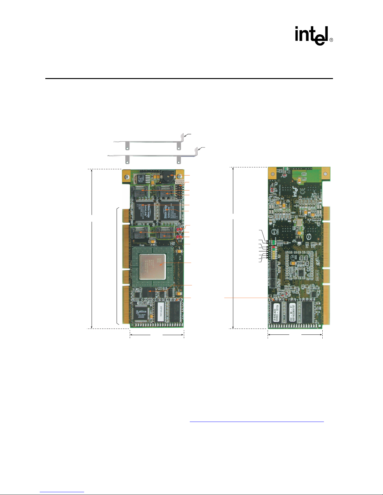
Figure 1. SRCS14L RAID Controller Physical Layout
167 mm
56 mm
Power
PCI bus speed
66MHz = on
33MHz =off
Status
DMA mode
Port-B:0 activity
Port-B:1 activity
Back View
Port-A:1 activity
Port-A:0 activity
167 mm
56 mm
Alarm
64MB ECC SDRAM
data cache
IOP mode select
jumper
(J1 )
Channel B
64-bit /
66MHz,
universally
keyed, 3.3
and 5 volt,
PCI interface
Intel
®
80303®
I/O processor
Front View
SATA connector B:0
SATA connector B:1
SATA Connector A:0
SATA connector A:1
SATA processor B
SATA processor A
4
MB Intel® Smart 3
FlashFile™ flash memory
Activity indicator header
PCI bus speed jumper
(J4 )
Standard bracket
Low-profile bracket
Page 9

Technical Product Specification
9
Intel® Integrated RAID Controller SRCS14L
2.2.1.1 Processor Core
The 80303 uses the 80960JT-100 core. The core processor runs at 100 MHz with an internal 64-bit
100 MHz PCI bus. Among other features, it contains a 128-bit register bus, 16Kbyte two-way
instruction cache, 4Kbyte direct-mapped data cache, 1Kbyte zero wait state data RAM, and single
clock execution of most instructions.
2.2.1.2 PCI-to-PCI Bridge
The PCI-to-PCI bridge features fully independent PCI bus operation with independent clocks,
dedicated data queues, 32-bit/33Mhz and 64-bit/66Mhz PCI bus support, and 64-bit Dual Address
Cycle addressing.
2.2.1.3 Memory Controller Unit
The Memory Controller provides direct control of memory systems external to the 80960 core
processor, including SDRAM and Flash. It features programmable chip selects, a wait state
generator, ECC single-bit correction and double-bit error detection. The bus interface to the
memory controller operates at 100 MHz. The SRCS14L uses 64MB of embedded memory.
2.2.2 Intel® Smart 3 FlashFile™ Flash Memory
This 3.3v, 32Mb (4MB) flash memory chip is used to store the RAID firmware. This non-volatile
storage can be accessed for firmware updates and recovery. For firmware recovery, set the IOP
mode select jumper J1 to reset; place jumper on pins 1 and 2. For normal firmware updates, place
the jumper on pins 2 and 3 (or remove totally). See Figure 2: Jumper Settings and Pin Numbers for
more information.
2.2.3 SDRAM (Cache)
The SRCS14L provides 64MB of 3.3v PC-100 ECC unbuffered CAS 2 latency SDRAM. The
memory is embedded in the RAID controller and is not upgradeable. It is connected directly to the
memory controller interface bus of the IOP, and serves as storage for the executable code
transferred from the flash. It also serves as cache during RAID transactions. Cache mode selection
takes immediate effect while the server is online. The IOP memory controller provides single-bit
ECC error correction.
2.2.4 SATA Controllers
The SRCS14L has two Silicon Image Sil3112A SATA controllers, which each control two serial
ports (four ports total). The Sil3112A can support data transfer rates up to 1.5 Gbps. See http://
www.siliconimage.com/products/sii3112.asp for more information.
2.2.5 Audible Alarm
An 80db audible alarm is mounted on the RAID controller to alert the user to a number of software
and/or hardware events experienced by the controller.
Page 10
10
Technical Product Specification
Intel® Integrated RAID Controller SRCS14L
2.2.6 SATA Connectors
The SRCS14L provides four SATA signal connectors.
2.2.7 PCI Interface
The SRCS14L has a 64-bit/66MHz PCI interface. The PCI connector is universally keyed for 3.3v
or 5v signaling and is PCI 2.2 compliant. The controller is designed for optimal performance when
inserted in a 64-bit/66MHz PCI expansion slot; however, it is backwards compatible with all
33MHz PCI expansion slots.
2.2.8 SRCS14L Jumpers
The IIR controller normally comes ready to be installed into the computer motherboard
immediately. However, jumper settings are available to:
• Reprogram the RAID firmware that is located in the flash memory of the IIR controller.
• Set the PCI bus speed (force 33 MHz or auto-negotiate 33/66 MHz).
For jumper locations and settings, see Table 2: Controller Jumper Settings and Figure 2: Jumper
Settings and Pin Numbers.
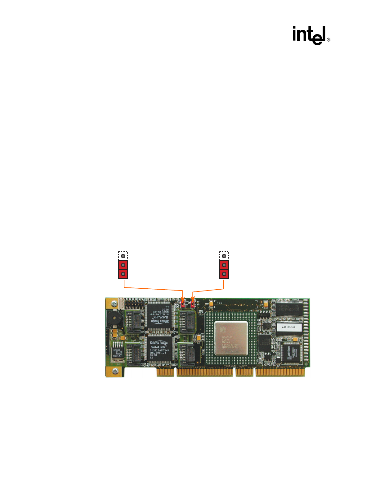
Figure 2. Jumper Settings and Pin Numbers
2
3
1
PCI Bus Speed (J4)
Auto-negotiate 33 or 66 MHz (pins 2-3)
Force 33 MHz (pins 1-2)
2
3
1
IOP Mode Select (J1)
Normal Mode (pins 2-3)
Recovery Mode (pins 1-2)
Page 11

Technical Product Specification
11
Intel® Integrated RAID Controller SRCS14L
J1 - IOP mode select jumper block: This jumper is used to place the IOP in reset, which enables the
flash chip to be programmed to recover resident firmware (FW). This is only necessary if the
content of the flash part is corrupted and needs to be erased and reprogrammed. The jumper is
installed on pins 1-2 to enable this function. During normal operation and during normal firmware
updates, the jumper is installed on pins 2-3 (or removed totally).
J4 - PCI bus speed: Leave this jumper in the default position (pins 2-3 to auto-negotiate 33/66
Mhz) unless instructed to do otherwise by customer support or a specification update.
2.2.9 Diagnostic Features
The SRCS14L has LED indicators and audible beep sequences at startup to help you understand
the status of the controller.
Table 2. Controller Jumper Settings
Jumper Block Jumper Position Definition
J1
Jumper on pins [1-2]
IOP is in reset mode with firmware recovery
enabled.
Jumper on pins [2-3] IOP is in normal run mode.
No jumpers IOP is in normal run mode.
J4
Jumper on pins [1-2] PCI bus is forced to 33 MHz.
Jumper on pins [2-3] PCI bus auto-negotiates 33 MHz or 66 MHz.
No jumpers PCI bus auto-negotiates 33 MHz or 66 MHz.
Figure 3. LED Labels and Colors
Table 3. LED Descriptions
LED Description
A:0 Indicates activity on SATA port A:0.
A:1 Indicates activity on SATA port A:1.
B:0 Indicates activity on SATA port B:0.
B:1 Indicates activity on SATA port B:1.
T Indicates data transfer to the controller’s cache memory.
S When illuminated, the controller's IOP is in reset mode.
P When illuminated, the controller card is powered on.
P66
When illuminated, PCI bus frequency is 66Mhz. When not illuminated, PCI bus frequency is
33Mhz.
A:0
A:1
T S P66P
green
yellow
yellow
green
red
green
yellow
yellow
yellow
B:0
B:1
Page 12

12
Technical Product Specification
Intel® Integrated RAID Controller SRCS14L
Table 4. Beep Sequences
Beep Sequence Meaning
beep - pause - beep, beep,
beep
Controller startup was successful.
beep, beep, beep, beep, ....
RAID controller has a problem. A possible cause is disk failure. To diagnose the
problem, run the Storage Console to check the status of the RAID controller
and array.
beep, beep - pause - beep,
beep - pause - ....
Memory or firmware may have a problem. More details may be available from
the boot message. If necessary, use the FRU utility to recover the firmware as
described in
Appendix A
of the SRCS14L hardware guide.
Page 13

Technical Product Specification
13
Intel® Integrated RAID Controller SRCS14L
2.3 Architecture Features (HW)
2.4 Electrical Characteristics
2.5 Environmental Specifications
2.6 Supported Hard Drive Technology
The RAID controller supports up to 4 hard disk drives connected to the 4 SATA ports. These hard
drives must be compliant with the SATA specification 1.0.
Table 5. Hardware Architecture
Component Features
I/O Microprocessor The 80303 processor: 100MHz, RISC 64-bit core
Cache Memory 3.3V unbuffered, PC100, ECC SDRAM. 64MB embedded not upgradeable
Flash Memory 3.3v, 32Mb (4MB) flash memory chip is used to store the RAID firmware
I/O interface (PCI) PCI 2.2 compliant, universally keyed for 3.3 and 5 volt PCI slots
PCI Transfer Rate 528 MB/sec (Burst) DMA to PCI and local buses
PCI Signaling +5 or +3.3 volt
SATA controllers
Two Silicon Image Sil3112A SATA controllers, which each control two serial
ports (four ports total) with speeds up to 1.5 Gbps
Table 6. Electrical Specifications
Attribute Measurements
Voltage Requirements +3.3 or +5 Volts (all +/– 5% tolerance)
Power Consumption
+5 Volts @ 0.25 Amps = 1.25W
+3.3 Volts @ 2.5 Amps = 8.25W
Table 7. Environmental Test Results
Environmental Stress Test Meets Required Conditions
Operating Temperature 0° C to +55° C
Storage Temperature -40° C to +70° C
Form Factor (physical dimensions)
Height: 56mm
Length: 167mm
Page 14

14
Technical Product Specification
Intel® Integrated RAID Controller SRCS14L
Software
3
3.1 Software Architecture Overview
The RAID software stack is composed of two major component groupings: the RAID firmware
embedded in the Flash memory and a set of host resident drivers and utilities installed on the host
system. All host-based software contains an OS dependent portion and an OS independent portion.
This allows for a consistent ‘look and feel’ across operating system platforms. A simple, custom
messaging protocol is used to communicate between the host driver or utility and the embedded
RAID firmware. The firmware is independent of the OS, I/O processor, and I/O bus through the
use of abstraction layers. This layered RAID software executes on a custom, multi-tasking, realtime software executive and relies on the reuse of internal software communication ‘building
blocks’ to incorporate new technology and provide for new products.
Figure 4. RAID Software Stack Architecture Block Diagram
PCI Bus
Operating System DriverPCI BIOS
API API API API
API (ROM)
Storage
Console
Storage
Console
(StorCon)
StorCon+
Windows
(GUI)
SNMP
Extension
Agent
IIR Service
/ IIRD
To Remote
StorCons
To Operating
System
Install
Programs
PCI Host Interface
Common
Firmware
I/O Processor
I/O Device
Page 15

Technical Product Specification
15
Intel® Integrated RAID Controller SRCS14L
Note: The architecture block diagram in Figure 4: RAID Software Stack Architecture Block Diagram is a
generalization. Its goal is to cover all OS implementations. Certain blocks may or may not be
relevant to each specific OS.
3.1.1 User Interface
3.1.1.1 Storage Console
The Storage Console is a text-based user interface. It is a full-featured monitoring and
configuration utility for managing all aspects of the RAID subsystem as well as many features of
the RAID controller. It can be accessed via two methods. The first is during system boot time when
entering the controller’s BIOS by depressing the <Ctrl>+<G> keys when prompted. The utility
accesses the RAID subsystem via the PCI BIOS.
The other method of accessing the Storage Console is via launching the application from within the
host operating system.
Storage Console communicates with the firmware via a common API both during system POST
and from within the host OS. This unique feature allows for a common user interface (UI) between
both OS and pre-OS environments.
3.1.1.2 Storage Console+
Storage Console+ provides a graphical user interface (GUI) for the Storage Console. However, it
runs only on Microsoft Windows-based systems and has the same features and functionality with
only a few exceptions.
3.1.2 System Management
3.1.2.1 RAID Mail Utility
The RAID Mail utility provides the RAID subsystem the ability to send notifications of specific
IIR events to remote computer stations. This utility takes certain messages generated by the RAID
Configuration Service and converts them into standard mail messages (for Windows NT/9x/200/
XP, in MAPI format). It relies on the IIR API for communication to the IIR specific information. It
can send messages locally (pop-up messages on local monitor) or to specific remote workstations.
It also can interface with standard email applications (like Microsoft Outlook or Exchange)
installed on the local system.
3.1.2.2 SNMP Extension Agent
The SNMP Extension Agent is the interface between SNMP and the IIR Management Information
Base (MIB). It interacts with the host resident MIB as well as the IIR HBA (via the IIR API) to
respond to SNMP requests.
Page 16

16
Technical Product Specification
Intel® Integrated RAID Controller SRCS14L
3.1.3 Common Layers
3.1.3.1 PCI BIOS
The PCI BIOS is the Expansion ROM software as defined in the PCI specification. It performs
IIR initialization from host system memory during POST.
3.1.3.2 IIR API
The IIR API is a C++ class library consisting of OS-independent classes and methods. This layer
encapsulates sequences of lower level C library API functions and builds OS independent data
structures used for communicating with the HBA. This API relies on an OS dependent layer that
communicates with the local driver (if one is present) or a remote driver via the TCP/IP or IPX/
SPX network protocol.
3.1.3.3 Operating System Driver
The IIR device driver is the OS specific driver that communicates between the host resident
application and the IIR HBA using the IIR communications protocol.
3.1.3.4 RAID Configuration Service
The IIR Service / IIRD allows remote access to the IIR HBA. It runs as a service on Windowsbased systems and as a daemon on Unix-based systems. In order to use the remote access
capability, an administrator has to create user accounts. The passwords for these accounts are
encrypted for security.
3.1.4 RAID Firmware
The IIR firmware is composed of multiple software layers allowing for maximum flexibility, reuse and maintainability. At the highest level is a host interface abstraction layer in the common
firmware that is also composed of multiple internal layers of service and library modules.
The I/O Device pictured next to the firmware (Figure 4: RAID Software Stack Architecture Block
Diagram) also communicates over an abstraction layer allowing for elegant integration of multiple
I/O device types from different vendors.
Page 17

Technical Product Specification
17
Intel® Integrated RAID Controller SRCS14L
RAID Functionality and Features
4
4.1 Hierarchy
A fundamental purpose of a RAID system is to present a usable (with some level of redundancy)
data storage medium (or drive) to a host operating system. In accomplishing this, the Intel RAID
firmware is based on a four level hierarchal model. Each level has its own drives associated with it.
The basic rule is to build drives on a given level in the hierarchy; the drives of the next lower level
are used as components. So, in order to create a data drive (host drive/RAID volume) and present it
to the host operating system, the RAID firmware typically follows these steps:
1. One or more physical drives are selected and initialized
2. A logical drive is created for each physical device
3. The logical drives are grouped and an array drive is created
4. The RAID firmware designates the array drive as a host drive and presents it to the host OS
4.1.1 Level 1: Physical Drives
Physical drives are located on the lowest level of the hierarchy. This includes hard disk drives,
removable hard disks, and some Magneto Optical drives. They are the basic components of all
drive constructions. However, before they can be used by the firmware, these hard drives must be
prepared by a process called initialization. During initialization each hard disk has configuration
information written to its physical medium in non-user accessible redundant areas. This
information allows a univocal identification even if the disk-ID or the controller is changed. For
reasons of data coherency, this information is extremely important for any drive construction
consisting of two or more physical drives.
4.1.2 Level 2: Logical Drives
Logical drives are constructed to obtain full independence of the physical coordinates of a
physical device. This is important because it allows one to rearrange the disk-IDs and channel
location of the physical drives of a disk array without compromising the integrity of the RAID
array disk. It also is what allows you to interchange disk arrays between compatible controllers.
You can create a logical drive manually by using one or more available physical drives. A logical
drive created manually in this way is presented directly to the host OS as a Host drive (see host
drives in Level 4). However, it is not associated with any array drive (see array drives in Level 3).
4.1.3 Level 3: Array Drives
Array drives are located at this level in the hierarchy. Array drives always consist of logical drives
and consist of the following drive types:
• RAID 0 drives
• RAID 1 drives
Page 18

18
Technical Product Specification
Intel® Integrated RAID Controller SRCS14L
• RAID 4 drives
• RAID 5 drives
• RAID 10 drives
You can manually create an array drive by using two or more logical drives that were manually
created at level 2. This action combines the original host drives associated with each of the logical
drives into a single host drive at a chosen RAID level.
4.1.4 Level 4: Host Drives
Host drives (RAID volumes) are created at the highest level of the hierarchy by the RAID
firmware. This is done automatically upon the creation of an array drive. It is also done
automatically upon the manual creation of a logical drive. Each host drive is assigned a drive
number that matches the drive number of its array drive or logical drive. Host drives are the only
hierarchal level drives that are detectable by the host operating system. The three lowest level
hierarchal drives are transparent to the host operating system.
After a capacity expansion of a given array drive, the added capacity appears to the host OS as a
new host drive on this level. It can then be configured as a separate host drive or, using the ‘Merge’
feature in the Host Drive menu, be combined with the initial host drive of the array drive into one
single host drive.
War ning: Any data located on the new host drive (created from the capacity expansion) will be lost using the
Merge feature. Do not use this feature if the new host drive already contains data that you do not
wish to destroy.
Within the Storage Console utility, each level of hierarchy has its own special menu:
Level 1 Menu: Configure Physical Devices
Level 2 Menu: Configure Logical Drives
Level 3 Menu: Configure Array Drives
Level 4 Menu: Configure Host Drives
Page 19

Technical Product Specification
19
Intel® Integrated RAID Controller SRCS14L
4.1.5 RAID Host/Array Drive Statuses
Table 8 lists the available states of RAID Host and Array Drives.
Table 8. Host Array Drive Statuses
Drive Status Attribute Drive Type Redundant Description
Idle RW RAID 4 / 5 / 10 No
Newly defined array prior to build
process starting.
Build RW RAID 1 / 4 / 5 / 10 No
The initial process of configuring
redundancy information upon creation
of drive.
Ready RW RAID 1 / 4 / 5 / 10 Yes
The array drive is fully operational, its
normal state.
Rebuild RW RAID 1 / 4 / 5 / 10 No
Array drive assumes this status after
the automatic activation of a Hot Fix or
after manual replacement (hot plug).
Expand RW RAID 4 / 5
Yes when
adding new
drives.
No when
using free
space.
This status indicates that the RAID
level and or capacity are (is) being
migrated.
The Expand status combines with the
Ready and Fail statuses as shown
below:
• Ready/Expand
• Fail/Expand
Fail RW RAID 1 / 4 / 5 / 10 No
This status indicates that a
logical
drive
has failed.
Error RO RAID 4 / 5 / 10 No
This status indicates that more that
one logical drive has failed. In this
event, the array is set to read only.
Patch RW RAID 4 / 5 Yes
This status indicates that the array
drive has gone through a significant
procedure or has been patched from
the error status to fail status.
The Patch status combines with other
statuses as shown below:
• Ready/Patch
• Fail/Patch
• Error/Patch
• Idle/Patch
• Rebuild/Patch
RW = Read Write
RO = Read Only
The drive
attribute
indicates the level of host OS
access to the drive
Page 20

20
Technical Product Specification
Intel® Integrated RAID Controller SRCS14L
4.1.6 Logical Drive Statuses
4.1.7 RAID Controller Drive Limitations (Host, Array, Logical, and
Physical)
The following are limitations assuming the following:
• Four SATA ports
• Cabling that meets SATA specifications 1.0
Physical drives are limited by the number of ports (four) on the RAID controller. Each physical
drive must be connected to one of the SATA ports. The maximum number of array drives is two. A
RAID array drive requires a minimum of two hard disk drives (or logical drives). Therefore the
maximum RAID array drive limitation for the SRCS14L controller is the physical drive limit
divided by two.
Each RAID array drive (up to two) can contain up to a maximum of two host drives. This means
that the SRCS14L controller has a maximum limitation of four host drives. Also, each array drive
must have at least one host drive. A host drive can only be associated with (or reside on) a single
array drive.
Table 9. Logical Drive Statuses
Drive Status Attribute Description
Ready RW The drive is operational and functioning normal.
Missing - The drive is missing or no longer detected by the RAID controller.
Fault RW The drive is no longer operating within expected parameters.
RW = Read Write
RO = Read Only
The drive
attribute
indicates the level of host OS access to the drive.
Table 10. RAID Controller Drive Maximum Limitations (SRCS14L)
Drive Type
Per RAID
Controller
Per Array Drive Per Host Drive
Physical Disk Drives 4 4 4
RAID Array Drives 2
N/A 1
RAID Host Drives 4 2
N/A
Page 21

Technical Product Specification
21
Intel® Integrated RAID Controller SRCS14L
4.2 Utilities and Tools
Table 11. Utilities And Tools
Management/Monitoring Description Actions
Storage Console (StorCon)
This is a text-based UI that allows full
management and monitoring of the RAID
controller and its subsystem. Consistent
look and feel across all supported operating
systems.
• Can be launched during
Boot up, <Ctrl>+<G>, or
within host OS
• Can be run locally or
remotely using TCP/IP or
SPX/IPX network protocols.
Storage Console+
(StorCon+)
GUI based version of the Storage Console
with exception to a few functions. It only runs
locally on Windows servers and clients.
• Can be run locally or
remotely using TCP/IP or
SPX/IPX network protocols.
Monitoring/Reporting Description
Actions
(using StorCon text-based)
View Statistics
Allows the viewing of I/O activity of host,
logical, and physical drives and cache
activity
From the menu, choose Express
or Advanced Setup -> View
Statistics. User can adjust synch
rate and enable and disable
logging.
View Events
Allows the viewing and saving of all events
regarding the controller since it’s last boot
up.
From the menu, choose Express
or Advanced Setup -> View
Events.
View Hard Disk Information
Lists all hard drives connected to the RAID
controller with information about each hard
drive
You can select each drive
individually to bring up a detailed
list of information that includes
detected defects since the drive
was first detected by the RAID
controller.
Diagnostics Description
Actions
(using StorCon text-based)
Save Information
Gives administrator the ability to save the
configuration information of the RAID
controller in ASCII file for viewing.
User can save file to be used for
troubleshooting or
documentation.
Memory Test
Non-destructive tests are written to ECC
memory and verified. The different modes
determine type of pattern and quantity.
Tests are not non-destructive for non-ECC
memory.
From the menu, choose
Advanced Setup -> Configure
Controller -> Controller Settings.
User selected options are: No
test, Standard, Double scan,
and Intensive.
Parity Verify
Selecting this feature causes the controller
to verify the parity on RAID level 4 and 5
arrays.
From the menu, choose
Advanced Setup -> Configure
Array Drives -> Select an array.
Check Surface: Physical
Disks
A destructive surface-check of the selected
hard disk drive. The controller writes and
reads certain data patterns and checks them
for correctness.
From the menu, choose
Advanced Setup -> Configure
Physical Devices ->Select
Physical Drive -> Check
Surface.
Warning! This action destroys
all data on the selected drive.
Page 22

22
Technical Product Specification
Intel® Integrated RAID Controller SRCS14L
4.3 RAID Features
4.3.1 RAID Level Support
4.3.2 Caching
There are two levels or modes of caching related to the controller - each independent of the other:
• Controller caching
• Disk drive caching
Firmware Description Actions
Firmware Update
Utility that allows the updating of the
controller’s firmware using:
• DOS utility for major updates (e.g.
major, 2.32.xx to 2.33.xx) or
• StorCon for minor updates (e.g. minor,
2.32.xx to 2.32.yz).
• Is accessed via DOS utility
• Is accessed via the Storage
Console during boot up
(<Ctrl>+<G>) or from within
the host OS menu
Advanced Setup ->
Configure Controller ->
Firmware Update
Firmware Recovery Utility to recover from corrupted firmware.
Requires that the controller’s J4
jumper be placed in the
Reset/
Firmware Recovery
mode and
the use of the DOS-based
firmware recovery utility.
Table 12. Supported RAID Levels
RAID Level Description
Drives
Requirements
0
Data striping. The SRCS14L can support only one
RAID O component.
2 min, 4 max
1 Drive mirroring. 2 min, 4 max
4 Data striping with dedicated parity drive. 3 min, 4 max
5 Data striping with distributed parity. 3 min, 4 max
10
Combination RAID 0 and 1, striped mirrors. The
SRCS14L does not support the addition of a hot
fix disk under RAID 10.
4 min, 4 max; drives must be added in
pairs
Disk Pass-Through to Host
Single Disk Presented to host OS as a host drive. 1
Chaining Presented to host OS as a host drive. 2 min, 4 max
Table 11. Utilities And Tools
Page 23

Technical Product Specification
23
Intel® Integrated RAID Controller SRCS14L
Caching can be enabled on the controller, which sets caching on all the RAID array/host drives
configured on the controller. This mode of caching utilizes the memory that is located on the
controller (SDRAM that is either embedded or an inserted DIMM module). The other caching
mode is enabling the caching feature of the hard disk drives. In this method, the cache memory
that is utilized is located on the disk drive and does not use the controller’s memory.
Warning: In the event of power loss to the computer system, data located in disk cache is not protected
by the battery backup unit of those controllers that support optional battery backup. The
battery backup only protects data that is located in the controller cache.
4.3.2.1 Controller Cache Selections
• Caching on/off selectable (sets all controller caching algorithms including Read Ahead to all
on or all off)
• Delayed Write on/off selectable (Write Back)
4.3.2.2 Physical Disk Cache Selections
• Read cache on/off selectable
• Write cache on/off selectable
Table 13. Supported Cache Settings
Cache Setting
Cache Configuration
Description
Disk Cache Controller Cache
1 Write _ Read _ Cache _
Delayed
Write
•_ No cache
2 Write _ Read • Cache _
Delayed
Write
•_ Disk Read
3Write• Read _ Cache _
Delayed
Write
•_ Disk Write
4Write• Read • Cache _
Delayed
Write
•_ Disk Read Write
5 Write _ Read _ Cache •
Delayed
Write
_ Controller Read
6 Write _ Read • Cache •
Delayed
Write
_ Disk Read, Controller Read
7Write• Read _ Cache •
Delayed
Write
_ Disk Write, Controller Read
8Write• Read • Cache •
Delayed
Write
_ Disk Read Write, Controller Read
9 Write _ Read _ Cache •
Delayed
Write
• Controller Read Write
10 Write _ Read • Cache •
Delayed
Write
• Disk Read, Controller Read Write
11 Wr ite • Read _ Cache •
Delayed
Write
• Disk Write, Controller Read Write
Page 24

24
Technical Product Specification
Intel® Integrated RAID Controller SRCS14L
4.3.3 Hot Fix (Spare) Disks
There are two types of hot fix drives:
• Private (dedicated): This type of hot fix drive is assigned to a specific RAID 4, 5, or 10 array
drive. It cannot be used by any other RAID array drive configured on the controller.
• Pooled (global): This type of hot fix drive is available for any RAID 1, 4, 5, or 10 array drive
that has been configured with Pooled Hot Fix Access enabled.
When adding a Pool Hot Fix to a specific array, the access for this array will be automatically
enabled, for other arrays this feature has to be manually activated with the Pool Hot Fix
Access switch.
The capacities of Hot fix drives are required to be the same size or larger than the capacity of the
smallest physical disk drive in the RAID array drives that they are protecting. Therefore, if you
have two RAID arrays where Array_1 has all 9 GB drives and Array_2 has all 18 GB drives then
Array_1 would require, at a minimum, a 9 GB hot fix drive and Array_2 would require, at a
minimum, an 18 GB hot fix drive.
Also, when using a single pooled hot fix drive to protect several RAID array drives, the pooled hot
fix drive must meet the proper capacity requirement to protect all of the arrays. To select the proper
sized pooled hot fix drive, first determine the capacity of the smallest physical disk drive in each
RAID array to be protected. Next, select a pooled hot fix drive that is equal to or larger than the
capacity of the largest of these disk drives. For example, in Table 14, if the pooled hot fix drive
for the four RAID arrays is 9GB, then it would only protect arrays 1 and 2. Therefore, the proper
hot fix drive selection to protect all four of the array drives would have to be of a minimum
capacity of 36GB (see note below).
12 Write • Read • Cache •
Delayed
Write
• Disk Read Write, Controller Read Write
Legend
_ diabled/off
• enabled/on
•_ either
Table 13. Supported Cache Settings
Cache Setting
Cache Configuration
Description
Disk Cache Controller Cache
Table 14. Example of a 9GB Pooled Hot Fix Drive
Selected to Protect Four Raid Array Drives
Array (smallest disk) Array_1 (4GB) Array_2 (9GB) Array_3 (18GB) Array_4 (36GB)
Protected by Pooled Hot Fix? Yes Yes No No
Note: This is only an example of how the pooled hot fix drive feature works. Obviously it would not
be practical to use only one pooled hot fix drive to protect all four of the arrays in this example unless hardware configuration limitation only allowed for one extra drive as a pooled hot fix (i.e. adding the pooled hot fix drive brings the total number of hard disk drives to the maximum supported
by the controller).
Page 25

Technical Product Specification
25
Intel® Integrated RAID Controller SRCS14L
4.3.4 Auto-detection of Hot-Plug Disk Drives in a Non-Intelligent
Drive Enclosure
This is a special feature that allows the use of non-intelligent disk enclosures (requires truly hotpluggable disk drives and backplane connectors) as though they were intelligent enclosures. This
feature is configurable and allows the user to set up non-intelligent enclosures to detect the
insertion or removal of hot plug disk drives and report the event to the RAID firmware. The RAID
configuration is automatically updated to the new configuration. Access this feature through the
Advanced Setup menu of Storage Console.
4.3.5 Auto-declare Hot Fix (Spare) Drive
If the RAID controller has a RAID array drive that is in failed (degraded) state, and you connect to
the controller a new hard disk drive that is the same size or larger than the smallest disk drive in
that failed (degraded) RAID array then the RAID firmware will automatically mark this new disk
drive as a hot fix (spare) drive for the failed (degraded) RAID array drive. Rebuild will then
automatically commence. If the new hard disk is smaller than the smallest hard disk drive in the
failed (degraded) RAID array drive, the new disk drive will not be marked as a spare and the failed
(degraded) RAID array drive will remain failed (degraded). When a non-intelligent enclosure that
has not been configured for auto-detection of hot plug disk drives is used, a bus scan or reboot is
required for the Auto Declare Hot Fix feature to commence.
4.3.6 RAID Array Drive Roaming
Array Roaming allows the user the ability to move a complete RAID array from one computer
system (for example, computer #1) to another computer system (computer #2) and preserve the
RAID configuration information and user data on that RAID array. Computer #2 must also have an
SRCS14L controller installed. RAID arrays set up with an SRCS14L controller cannot roam to
computers that use other controllers.
Note: For a migrated RAID array to be recognized by the new host operating system, the host system
may need to be rebooted.
Warning: RAID arrays set up with an SRCS14L controller cannot roam to computers that use other
controllers (anything other than the SRCS14L). Unpredictable behavior may include, but is not
limited to, data loss or corruption.
4.3.7 On-line RAID Array Configurations
4.3.7.1 Capacity Expansion Without Reboot
On-line capacity expansion refers to the ability of the RAID controller to present new storage space
to the host OS without requiring that the computer system must be taken off-line and rebooted (for
those Operating systems that support this feature). The host OS is able to detect the new capacity
and format and partition it for immediate use. The RAID controller offers several ways of creating
additional capacity while on-line.
Creating new RAID array drives from available physical hard disk drive:
Page 26

26
Technical Product Specification
Intel® Integrated RAID Controller SRCS14L
This is the simplest method. The user just creates a new host drive from available physical disk
drives that are connected to the RAID controller (the assumption here is that there were disk drives
that were already connected but unused or there were new disk drives inserted into open slots in a
hot plug drive enclosure already connected to the RAID controller)
Creating new capacity to existing RAID array components (Expand Array Drive):
Using this method you are allowed to do one of the following:
• Convert unused free space on the existing logical drives of the RAID array drive into a
separate host drive, or
• Add additional physical disk drives to the existing RAID array drive
4.3.7.2 RAID Level Migration
RAID level migration is accomplished using the Expand Array Drive feature. To expand a RAID 0
drive to a RAID 4 or 5, requires that you add at least one additional drive to the array. Migrating
from RAID 4 or 5 to RAID 0 frees one disk. The RAID controller allows the following RAID level
migrations of a given array drive:
RAID 0 RAID 4: add new disk, parity is calculated and written to new disk
RAID 0 RAID 5: add new disk, parity calculated and written to new disk, then parity is
distributed over all disk
RAID 5 RAID 0: parity written to one disk, parity disk freed and removed
RAID 4 RAID 0: parity disk freed and removed
RAID 4 RAID 5: parity distributed over all disk
RAID 5 RAID 4: parity written to one disk
Basic migration process: RAID 0 < --> RAID 4 < -- > RAID 5
To initiate a migration the RAID array must be have a status of ready.
4.3.7.3 Data Strip Size Configurable per RAID Array
The strip size for each RAID array can be configured at the time of creation of the RAID array.
This is a one-time configuration and cannot be changed or migrated once the array has been
created. For RAID 0, 4, 5, and 10 arrays the following Strip Sizes are possible:
• 16KB
• 32KB
• 64KB
• 128KB
Page 27

Technical Product Specification
27
Intel® Integrated RAID Controller SRCS14L
4.3.8 Background Initialization and Instant Availability
The initialization of RAID array drives is done in the background. Array drives have a status of
build during this process and are immediately accessible to the host OS if the host OS supports
online capacity expansion.
There are two build modes available when creating RAID arrays, Non-destructive and Destructive.
Destructive is much faster than the standard build mode. When in destructive build mode, the
firmware writes a pattern of zeros across all disks. If this build process is interrupted by rebooting
the computer, the build process will continue in the much slower non-destructive build mode.
4.3.9 PCI Hot Plug
The controller supports the PCI hot plug specification for Windows. It supports the hot replace
function only.
Page 28

28
Technical Product Specification
Intel® Integrated RAID Controller SRCS14L
Certifications and Supported
Technologies
5
5.1 OS Certifications
The product will be validated with the latest vendor OS certification test suites. Pre-submission
tests will be passed and the certifications listed in Table 1 5 will be submitted to the proper
submission process as required per OS. The pre-submission test will be run on the final gold
production release candidate of the RAID software suite OS drivers and RAID firmware. The
product will not be held up from shipping while awaiting final passing notification from the OS
vendors (and in the case of Windows 2000, the digitally signed versions of the OS driver).
Table 15. OS Certification Requirements
OS Vendor Details Test Suite Version
Red Hat Linux
The product shall be certified to receive “Red Hat
Ready” certification for the following:
• Red Hat Linux 7.3 (the 2.4 kernel)
Test suite ver. 1.6.9 or latest
Page 29

Technical Product Specification
29
Intel® Integrated RAID Controller SRCS14L
5.2 Electronic Regulatory Agencies Certifications
(Hardware)
Table 16. Electronic Equipment Regulatory Certifications
Country/
Region
Applicable Speci-
fication
Agency Certifica-
tions
Product Labeling Manual Statements
U.S.A.
(EMC)
FCC part 2; FCC
part 15, subpart B,
Class A
Class A
verification testing
only. No
laboratory
accreditation
required.
FCC Class A statement on
product, product packaging,
or prominently located in the
users manual, as follows:
This device complies with
part 15 of the FCC Rules.
Operation is subject to the
following two conditions: (1)
This device may not cause
harmful interference, and
(2) this device must accept
any interference received,
including interference that
may cause undesired
operation.
FCC Class A statements prominently
located in users manual, as follows:
Note: This equipment has been
tested and found to comply with the
limits for a Class A digital device,
pursuant to part 15 of the FCC
Rules. These limits are designed to
provide reasonable protection
against harmful interference when
the equipment is operated in a
commercial environment. This
equipment generates, uses, and can
radiate
radio frequency energy and, if not
installed and used in accordance
with the instruction manual, may
cause harmful interference to
radio communications. Operation
of this equipment in a residential
area is likely to cause harmful
interference in which case the
user will be required to correct the
interference at his own expense.
Plus, the users manual shall caution
the user that changes or
modifications not expressly
approved by Intel Corp. could void
the user's authority to operate the
equipment.
U.S.A.
and
Canada
(safety)
UL Accessory
Listing to
UL60950, 3
rd
ed.
and CAN/CSA
C22.2 No 6095000
UL and ULCanada safety
certification
UL/UL-Canada Accessory
Listing mark, includes Intel
file no. E139761, and I.T.E.
product category; UL pwb
fabricator mark; and V-0 or
V-1 flame rating mark.
No known UL required safety
statements.
Canada
(EMC)
ICES-003 Digital
Apparatus, Class
A. Note, FCC or
CISPR 22:1993
limits accepted in
lieu of ICES-003
Class A
verification testing
only. No
laboratory
accreditation
required.
Industry Canada Class A
statement on product,
product packaging, or
prominently located in the
user’s manual, as follows:
This Class A digital
apparatus complies with
Canadian ICES-003.
French version is optional,
as follows: Cet appereil
numÈrique de la classe (*)
est conforme ‡ la norme
NMB-003 du Canada.
No additional statements.
Page 30

30
Technical Product Specification
Intel® Integrated RAID Controller SRCS14L
European
Union
(EMC)
EN55022:1998
Class A
(emissions)
Manufacturer’s
Declaration of
Conformity (DoC)
to the EMC
directive. No
laboratory
accreditation
required.
CE mark on board or
alternately, CE mark on
product packaging.
Minimum 5mm in height.
Declaration of Conformity statement,
plus CE mark, plus the following
(including translations), This
product follows the provisions of
the European Directive 89/336/
EEC (EMC) and Directive 73/23/
EEC (Safety/LVD).
European
Union
(EMC)
EN55024:1998
(immunity),
consists of IEC
61000-4-2 (ESD),
IEC 61000-4-3
(radiated
immunity), IEC
61000-4-4 (EFT),
IEC 61000-4-5
(surge), IEC
61000-4-6
(conducted
immunity), and
IEC 61000-4-11
(voltage dips and
interrupts)
Same as EN55022
(EMI)
requirements
above
Same as EN55022 (EMI)
requirements above.
Same as EN55022 (EMI)
requirements above.
European
Union
(safety)
EN 60950, 3
rd
ed.
Manufacturer’s
Declaration of
Conformity (DoC)
to the Low Voltage
directive. No
laboratory
accreditation
required.
Same as EN55022 (EMI)
requirements above.
Same as EN55022 (EMI)
requirements above.
Australia,
New
Zealand
(EMC)
AS/NZS 3458:
1995 (CISPR
22:1993), Class A
Manufacturer’s
Declaration of
Conformity (DoC)
C-Tick mark with Intel
supplier code no. (N232) on
board or product packaging.
None.
Korea
(EMC)
Nat’l standards w/
emissions based
on CISPR 22:1997
and immunity
based on CISPR
24 with EN 55024:
1998 type
modifications
In-country testing
required at an RRL
(Radio Research
Laboratory)
accredited lab.
Korean MIC (Ministry of
Information and
Communication) logo mark
on board or product
packaging.
Korean MIC (Ministry of Information
and Communication) logo mark plus
Korean certification text
Taiwan
(EMC)
CNS 13438
(CISPR22)
Information
Technology
Equipment
Test at a BSMI
accredited lab or
an A2LA or NIST
NVLAP accredited
lab that is notified
to BSMI by NIST
Taiwan registration DoC
logo mark on board or
product packaging.
Traditional Chinese BSMI Class A
text in users manual.
Australia,
New
Zealand,
Taiwan,
Korea,
other
APAC
(safety)
IEC 60950, 3
rd
ed.
(aka CB report w/
CB certificate)
Notified body test
house required,
e.g., UL, Nemko,
etc.
None. None.
Page 31

Technical Product Specification
31
Intel® Integrated RAID Controller SRCS14L
5.3 Supported Specifications and Standards
Table 17. Supported Standards and Specifications
Specification/Standard Details
BIOS Boot Specification ver 1.01 http://www.phoenix.com/PlatSS/PDFs/specs-bbs101.pdf
PnP BIOS Specification 1.0a http://www.microsoft.com/hwdev/tech/pnp/default.asp
El Torito CD-ROM Boot v1.0
• The product supports booting from a CD-ROM based on the “El
To ri t o” Bootable CD-ROM Format Specification, version 1.0, http://
www.phoenix.com/PlatSS/PDFs/specs-cdrom.pdf
• The product supports a bootable CD-ROM from a PCI 2.2 Plug and
Play compliant BIOS.
• The product supports No Emulation mode with PnP BIOSs.
PCI BIOS 2.1 http://www.pcisig.com/specifications/pci_bios
PCI Power Management 1.1
http://www.pcisig.com/specifications/
pci_bus_power_management_interface
PCI Local Bus Specification Rev
2.2
http://www.pcisig.com/specifications/conventional_pci
PCI Local Bus Specification Rev
2.2 Low Profile PCI card ECN
http://www.pcisig.com/data/specifications/reset_ecn1_011300.pdf (for
members only)
Microsoft Hardware Design
Guide Version 3.0
http://www.microsoft.com/hwdev/serverdg.htm#Design3
Power Management (ACPI and
OnNow)
• The product supports power states D0, and D3 as defined by Storage
Device Class Power Management Reference Specification, Microsoft,
Version 1.0A, February 1997.
• The product supports power state D3 as follows:
• Drive controller (i.e., interface and control electronics): not
functional; context lost
• Interface mode (i.e., communications timings): not
preserved
• Drive motor (i.e., spindle): stopped
POST Memory Manager
Specification, Version 1.01
http://www1.phoenix.com/PlatSS/PDFs/specs-pmm101.pdf
Note that compliance in this case does not mean usage of calls outlined in
the spec. We do not use PMM calls however we do not violate the
specification.
NetWare Peripheral Architecture
(NWPA)'
http://developer.novell.com/ndk/storarch.htm
(Username and Password Required)
Silicon Image Sil3112 http://www.siliconimage.com/products/sii3112.asp
SATA 1.0 Specification 1.0 http://www.serialata.org/cgi-bin/SpecDownload.cgi
ATA/ATAPI-5 T13 1321D, Rev. 3, 29 February 2000
ATA/ATAPI-6 (for 48bit LBA
support)
T13 1410D, Rev. 1e, 26 June 2001.
Page 32

32
Technical Product Specification
Intel® Integrated RAID Controller SRCS14L
Technical Drawings and Diagrams
6
Figure 5. Controller PBA Drawing, Front View
Figure 6. Controller PBA Drawing, Back View
Page 33

Technical Product Specification
33
Intel® Integrated RAID Controller SRCS14L
Appendices
7
7.1 Referenced Documentation
7.2 BIOS Boot Messages
TBD.
Table 18. Referenced Documentation
Document Title Order #
SRCS14L Hardware Installation and User’s Guide 251554-001
Software Installation and User’s Guide 273479-002
 Loading...