

Page 1

Intel® Server System
SR9000MK4U Product Guide
Intel Order Number D71314-004
Page 2

Disclaimer
Information in this document is provided in connection with Intel® products. No license, express or implied, by
estoppel or otherwise, to any intellectual property rights is granted by this document. Except as provided in Intel's
Terms and Conditions of Sale for such products, Intel assumes no liability whatsoever, and Intel disclaims any
express or implied warranty, relating to sale and/or use of Intel products including liability or warranties relating to
fitness for a particular purpose, merchantability, or infringement of any patent, copyright or other intellectual property
right. Intel products are not designed, intended or authorized for use in any medical, life saving, or life sustaining
applications or for any other application in which the failure of the Intel product could create a situation where
personal injury or death may occur. Intel may make changes to specifications and product descriptions at any time,
without notice.
Intel server boards contain a number of high-density VLSI and power delivery components that need adequate
airflow for cooling. Intel's own chassis are designed and tested to meet the intended thermal requirements of these
components when the fully integrated system is used together. It is the responsibility of the system integrator that
chooses not to use Intel developed server building blocks to consult vendor datasheets and operating parameters to
determine the amount of airflow required for their specific application and environmental conditions. Intel Corporation
can not be held responsible if components fail or the server board does not operate correctly when used outside any
of their published operating or non-operating limits.
Intel, Intel Pentium, and Intel Xeon are trademarks or registered trademarks of Intel Corporation or its subsidiaries in
the United States and other countries.
* Other names and brands may be claimed as the property of others.
Copyright © 2006-2007, Intel Corporation. All Rights Reserved
ii Intel® Server System SR9000MK4U Product Guide
Page 3

Safety Information
Important Safety Instructions
Read all caution and safety statements in this document before performing any of the
instructions. See also Intel Server Boards and Server Chassis Safety Information on the
Resource CD and/or at http://support.intel.com/support/motherboards/server/sb/cs-
010770.htm.
Wichtige Sicherheitshinweise
Lesen Sie zunächst sämtliche Warnund Sicherheitshinweise in diesem Dokument, bevor
Sie eine der Anweisungen ausführen. Beachten Sie hierzu auch die Sicherheitshinweise zu
Intel-Serverplatinen und Servergehäusen auf der Resource CD oder unter http://
support.intel.com/support/motherboards/server/sb/cs-010770.htm.
Consignes de sécurité
Lisez attention toutes les consignes de sécurité et les mises en garde indiquées dans ce
document avant de suivre toute instruction. Consultez Intel Server Boards and Server
Chassis Safety Information sur le Resource CD ou bien rendez-vous sur le site http://
support.intel.com/support/motherboards/server/sb/cs-010770.htm.
Instrucciones de seguridad importantes
Lea todas las declaraciones de seguridad y precaución de este documento antes de realizar
cualquiera de las instrucciones. Vea Intel Server Boards and Server Chassis Safety
Information en el Resource CD y/o en http://support.intel.com/support/motherboards/
server/sb/cs-010770.htm.
iii
Page 4
重要安全指导
Warnings
Heed safety instructions: Before working with your server product, whether you are
using this guide or any other resource as a reference, pay close attention to the safety
instructions. You must adhere to the assembly instructions in this guide to ensure and
maintain compliance with existing product certifications and approvals. Use only the
described, regulated components specified in this guide. Use of other products /
components will void the UL listing and other regulatory approvals of the product and
will most likely result in noncompliance with product regulations in the region(s) in which
the product is sold.
System power on/off: The power button DOES NOT turn off the system AC power. To
remove power from system, you must unplug the AC power cord from the wall outlet.
Make sure the AC power cord is unplugged before you open the chassis, add, or remove
any components.
Hazardous conditions, devices and cables: Hazardous electrical conditions may be
present on power, telephone, and communication cables. Turn off the server and
disconnect the power cord, telecommunications systems, networks, and modems attached
to the server before opening it. Otherwise, personal injury or equipment damage can
result.
Electrostatic discharge (ESD) and ESD protection: ESD can damage disk drives,
boards, and other parts. We recommend that you perfo rm all procedures in this chapter
only at an ESD workstation. If one is not available, provide some ESD protection by
wearing an antistatic wrist strap attached to chassis ground any unpainted metal surface on
your server when handling parts.
ESD and handling boards: Always handle boards carefully. They can be extremely
sensitive to ESD. Hold boards only by their edges. After removing a board from its
protective wrapper or from the server, place the board component side up on a grounded,
static free surface. Use a conductive foam pad if available but not the board wrapper. Do
not slide board over any surface.
iv Intel® Server System SR9000MK4U Product Guide
Page 5

Installing or removing jumpers: A jumper is a small plastic encased conductor that slips
over two jumper pins. Some jumpers have a small tab on top that you can grip with your
fingertips or with a pair of fine needle nosed pliers. If your jumpers do not have such a tab,
take care when using needle nosed pliers to remove or install a jumper; grip the narrow
sides of the jumper with the pliers, never the wide sides. Gripping the wide sides can
damage the contacts inside the jumper, causing intermittent problems with the function
controlled by that jumper. Take care to grip with, but not squeeze, the pliers or other tool
you use to remove a jumper, or you may bend or break the pins on the board.
Intel® Server System SR9000MK4U Product Guide v
Page 6

vi Intel® Server System SR9000MK4U Product Guide
Page 7

Preface
About this Manual
Thank you for purchasing and using Intel® server products.
This manual is written for system technicians who are responsible for troubleshooting,
upgrading, and managing the Intel
provides an overview of the features of the server system utilities, and instructions on how
to install, setup, and manage the system. For the latest version of this manual, see http://
support.intel.com/support/motherboards/server/SR9000MK4U/.
Manual Organization
Chapter 1 provides a brief overview of the chassis features for the Server System
SR9000MK4U.
Chapter 2 provides an overview of the features of the boards used in the Server System
SR9000MK4U.
In this chapter, you will find a list of the server board features, photos of the product, and
product diagrams to help you identify components and their locations.
Chapter 3 provides instructions for adding and replacing components. Use this chapter for
step-by-step instructions and diagrams for installing or replacing components such as the
hard drives, memory, processor, fans, boards and other components.
Chapter 4 tells you how to install the system into a rack environment.
®
Server System SR9000MK4U. This document
Chapter 5 provides instructions on using the utilities that are shipped with the board or
that may be required to update the system. This includes how to navigate through the
BIOS Setup screens, and how to clear the CMOS.
Chapter 6 provides troubleshooting information. In this chapter, you will fi nd suggestions
and steps to follow for performing troubleshooting activities to identify the source of a
problem.
Appendices provide tables of POST codes, SEL codes, safety information, safety start-up
warnings, and how to get help.
vii
Page 8
Product Accessories
You may need or want to purchase one or more of the following accessory items for your
server:
Processor, memory DIMMs, hard drive, USB floppy drive, CD-ROM or DVD-ROM
drive, RAID controller, operating system.
For information about which accessories, memory, processors, and third-party hardware
have been tested and can be used with your board, and for ordering information for Intel
products, see http://support.intel.com/support/motherboards/server/SR9000MK4U/
compat.htm.
Additional Information and Software
If you need more information about this product or information about the accessories that
can be used with this server board, use the following resources. These files are available at
http://support.intel.com/support/motherboards/server/SR9000MK4U/
Unless otherwise indicated in the table below, once on this Web page, type the document
or software name in the search field at the left side of the screen and select the option to
search “This Product.”
Table 1. Additional Information and Software
For this information or
software
For in-depth technical
information about this
product, including BIOS
settings and chipset
information
If you just received this
product and need to
install it
Accessories or other Intel
server products
Hardware (peripheral
boards, adapter cards)
and operating systems
that have been tested with
this product
Processors that have
been tested with this
product
Use this Document or Software
®
Intel
Server System SR9000MK4U Technical Product
Specification
®
Server System SR9000MK4U Quick Start User's Guide in the
Intel
product box
Spares and Configuration Guide
Tested Hardware Operating Systems List
Supported Processors
viii Intel® Server System SR9000MK4U Product Guide
Page 9
Table 1. Additional Information and Software
For this information or
software
DIMMs that have been
tested with this product
For drivers Driver (for an extensive list of available drivers)
For firmware and BIOS
updates, or for BIOS
recovery
For diagnostics test
software
Tested Memory List
Operating System Driver (for operating system drivers)
Firmware Updates
Diagnostics
Use this Document or Software
See also the Resource CD that came with your server system.
Intel® Server System SR9000MK4U Product Guide ix
Page 10

Powering the System On and Off
Powering On the System Power
1. Connect the power cables to AC input power connectors in the back of the system
and to the outlet. If 100 - 110 VAC is used, both power supplies must be connected.
2. If peripheral devices are attached that need to be turned on first, power on these
peripherals. See your peripheral guides for information.
3. Press the power button on the front panel. The green power LED will light.
4. Watch the fault LED on the front panel for any signs of trouble. See the
troubleshooting information at the end of this manual for help if necessary.
Powering Off the System Power
1. If peripheral devices are attached that need to be turned off first, power off these
peripherals. See your peripheral guides for information.
2. Press the power button on the front panel. The green power LED will turn off.
Note: The system will force a power off if the power button is held down for four or more
seconds. This method should be used only if the system has locked up. If the power is
forced off, wake events, such as Wake-on-LAN, are disabled. The IPMI “Power Off”
command functions the same way as a four-sec ond button pr ess. When the system power is
forced off, either the power button or the IPMI “Power On” command must be used to
power the system back on.
x Intel® Server System SR9000MK4U Product Guide
Page 11

Contents
Safety Information ..................................................................................................... iii
Important Safety Instructions ................................................................................................ iii
Wichtige Sicherheitshinweise ............................................................................................... iii
Consignes de sécurité .......................................................................................................... iii
Instrucciones de seguridad importantes ............................................................................... iii
Warnings ............................................................................................................................... iv
Preface .......................................................................................................................vii
About this Manual ................................................................................................................ vii
Manual Organization ............................................................................................................vii
Product Accessories ............................................................................................................viii
Additional Information and Software ....................................................................................viii
Powering the System On and Off ..........................................................................................x
Powering On the System Power ....................................................................................x
Powering Off the System Power ....................................................................................x
Chapter 1: Intel® Server System SR9000MK4U Chassis Overview ....................... 1
Chassis Description ...............................................................................................................2
External Chassis Features .....................................................................................................3
Chassis Front ................................................................................................................4
Chassis Rear .................................................................................................................9
Internal Layout .............................................................................................................11
Internal Chassis Features ....................................................................................................12
Power Supply Subsystem ............................................................................................12
Cooling Subsystem ......................................................................................................14
PCI Card Slot ...............................................................................................................15
Chapter 2: Intel® Server System SR9000MK4U Board Set Overview .................. 17
Main Board ..........................................................................................................................18
Configuration Restrictions ...........................................................................................22
Processor Configurations ............................................................................................23
Memory Box Card ................................................................................................................24
DIMM Configurations ...................................................................................................25
Hard Drive Backplane ..........................................................................................................29
Hard Drive Population .................................................................................................30
Front Panel Board ................................................................................................................30
Chapter 3: Installing and Removing Components ................................................ 33
Tools Needed ......................................................................................................................33
Installing and Removing the Front Bezel .............................................................................34
Removing the Front Bezel ...........................................................................................34
Intel® Server System SR9000MK4U Product Guide xi
Page 12

Installing the Front Bezel ............................................................................................. 35
Installing and Removing the Top Cover .............................................................................. 36
Removing the Top Cover ............................................................................................ 36
Installing the Top Cover .............................................................................................. 37
Installing and Removing a Hard Drive ................................................................................. 37
Installing a Hard Drive ................................................................................................. 38
Removing a Hard Drive ............................................................................................... 40
Hot-swapping a Hard Drive ......................................................................................... 42
Installing and Removing a Memory Box .............................................................................. 42
Installing a Memory Box .............................................................................................. 43
Removing a Memory Box ............................................................................................ 45
Hot-swapping a Memory Box ...................................................................................... 46
Installing and Removing DIMMs .......................................................................................... 48
DIMM Installation Guidelines ...................................................................................... 48
Installing DIMMs .......................................................................................................... 49
Removing DIMMs ........................................................................................................ 50
Installing and Removing an Optical Drive ........................................................................... 51
Installing an Optical Drive ........................................................................................... 51
Removing the Optical Drive ........................................................................................ 53
Installing and Removing a Fan ............................................................................................ 55
Installing a Fan ............................................................................................................ 55
Removing a Fan .......................................................................................................... 57
Hot-swapping a Fan .................................................................................................... 58
Installing and Removing a PCI Card ................................................................................... 59
Installing a PCI Card ................................................................................................... 59
Removing a PCI Card ................................................................................................. 63
Hot-Plugging a PCI Card ............................................................................................. 67
Installing and Removing a Power Supply ............................................................................ 68
Installing a Power Supply ............................................................................................ 68
Removing a Power Supply .......................................................................................... 70
Hot-swapping a Power Supply .................................................................................... 73
Installing and Removing the Front Control Panel and Optical Drive Assembly ................... 74
Removing the Front Control Panel and Optical Drive Assembly ................................. 74
Installing the Front Control Panel and Optical Drive Assembly ................................... 75
Installing and Removing the Power Supply Box .................................................................. 76
Removing the Power Supply Box ................................................................................ 76
Installing the Power Supply Box .................................................................................. 80
Installing and Removing the Power Supply Support ........................................................... 83
Removing the Power Supply Support ......................................................................... 83
Installing the Power Supply Support ........................................................................... 85
Installing and Removing the Hard Drive Backplane Cover ................................................. 87
Removing the Hard Drive Backplane Cover ............................................................... 87
Installing the Hard Drive Backplane Cover ................................................................. 88
Installing and Removing the KVM Card .............................................................................. 89
xii Intel® Server System SR9000MK4U Product Guide
Page 13

Removing the KVM Card .............................................................................................89
Installing the KVM Card ...............................................................................................90
Installing and Removing the PCI Card Divider ....................................................................91
Removing the PCI Card Divider ..................................................................................91
Installing the PCI Card Divider ....................................................................................93
Installing and Removing the Air Flow Guide ........................................................................95
Removing the Air Flow Guide ......................................................................................95
Installing the Air Flow Guide ........................................................................................97
Installing and Removing the Fan Box ..................................................................................98
Removing the Fan Box ................................................................................................98
Installing the Fan Box ................................................................................................101
Installing and Removing the Hard Drive Backplane ..........................................................103
Removing the Hard Drive Backplane ........................................................................103
Installing the Hard Drive Backplane ..........................................................................107
Installing and Removing a Processor ................................................................................110
Removing a Processor ..............................................................................................111
Installing the Processor .............................................................................................113
Disassembling a Processor Assembly ...............................................................................122
Installing and Removing the Mounting Plate .....................................................................125
Removing the Mounting Plate ...................................................................................125
Installing the Mounting Plate .....................................................................................127
Installing and Removing Chassis Handles ........................................................................129
Installing Chassis Handles ........................................................................................129
Removing Chassis Handles ......................................................................................129
Chapter 4: Configuration Software and Utilities .................................................. 131
The Extensible Firmware Interface (EFI) Boot Manager ...................................................131
The Extensible Firmware Interface (EFI) Shell ..................................................................134
LSI* SAS Utility ..................................................................................................................137
Formatting a Hard Drive ............................................................................................137
Clearing the CMOS ............................................................................................................140
Upgrading the Firmware ....................................................................................................140
How to Use FWUPDATE ...........................................................................................142
Execution Screen ......................................................................................................144
Using System Setup ..........................................................................................................145
Starting Setup ............................................................................................................145
Recording Your Setup Settings .................................................................................145
Navigating Setup Utility Screens ...............................................................................146
Primary Screens ........................................................................................................146
Configuring Serial-Over LAN .............................................................................................151
Chapter 5: Troubleshooting .................................................................................. 153
Initial Troubleshooting Steps .............................................................................................153
Collecting System State Information ..................................................................................156
How to Read the POST Codes ..................................................................................159
Intel® Server System SR9000MK4U Product Guide xiii
Page 14

How to Use Selview to Read the System Event Log ................................................ 160
How to Collect System and Error Logs ..................................................................... 160
Taking Corrective Action ................................................................................................... 162
Appendix A: Console Setup ...................................................................................163
On-board VGA ...................................................................................................................163
Serial Console ................................................................................................................... 165
Appendix B: Cabling ...............................................................................................167
Working with Ribbon Cables ............................................................................................. 167
Cable Connections ............................................................................................................ 168
Appendix C: POST Codes ......................................................................................171
Appendix D: Installation/Assembly Safety Instructions .....................................181
English ............................................................................................................................... 181
Deutsch ............................................................................................................................. 183
Français ............................................................................................................................. 185
Español ............................................................................................................................. 187
Italiano ............................................................................................................................... 189
Appendix E: Safety Information ............................................................................193
Warning Labels .................................................................................................................193
English ............................................................................................................................... 195
Server Safety Information ......................................................................................... 195
Safety Warnings and Cautions .................................................................................. 196
Intended Application Uses ........................................................................................ 196
Site Selection ............................................................................................................ 197
Equipment Handling Practices .................................................................................. 197
Power and Electrical Warnings ................................................................................. 198
System Access Warnings ......................................................................................... 199
Rack Mount Warnings ............................................................................................... 200
Electrostatic Discharge (ESD) ................................................................................... 200
Other Hazards ........................................................................................................... 201
Deutsch ............................................................................................................................. 202
Sicherheitshinweise für den Server ........................................................................... 202
Sicherheitshinweise und Vorsichtsmaßnahmen ....................................................... 202
Zielbenutzer der Anwendung .................................................................................... 203
Standortauswahl ....................................................................................................... 203
Handhabung von Geräten ......................................................................................... 204
Warnungen zu Netzspannung und Elektrizität .......................................................... 204
Warnhinweise für den Systemzugang ....................................................................... 205
Warnhinweise für Racks ........................................................................................... 206
Elektrostatische Entladungen (ESD) ......................................................................... 206
Andere Gefahren ....................................................................................................... 207
Français ............................................................................................................................. 208
xiv Intel® Server System SR9000MK4U Product Guide
Page 15

Consignes de sécurité sur le serveur ........................................................................208
Sécurité: avertissements et mises en garde ..............................................................208
Domaines d’utilisation prévus ....................................................................................209
Sélection d’un emplacement .....................................................................................209
Pratiques de manipulation de l’équipement ...............................................................209
Alimentation et avertissements en matière d’électricité .............................................210
Avertissements sur l’accès au système .....................................................................211
Avertissements sur le montage en rack ....................................................................212
Décharges électrostatiques (ESD) ............................................................................212
Autres risques ............................................................................................................212
Español ..............................................................................................................................214
Información de seguridad del servidor ......................................................................214
Advertencias y precauciones sobre seguridad ..........................................................214
Aplicaciones y usos previstos ....................................................................................215
Selección de la ubicación ..........................................................................................215
Manipulación del equipo ............................................................................................215
Advertencias de alimentación y eléctricas .................................................................216
Advertencias el acceso al sistema ............................................................................217
Advertencias sobre el montaje en bastidor ...............................................................218
Descarga electrostática (ESD) ..................................................................................218
Appendix F: Getting Help ...................................................................................... 225
World Wide Web ................................................................................................................225
Telephone ..........................................................................................................................225
Appendix G: Regulatory and Compliance Information ....................................... 229
Product Regulatory Compliance ........................................................................................229
Product Safety Compliance .......................................................................................229
Product EMC Compliance - Class A Compliance ......................................................230
Certifications / Registrations / Declarations ...............................................................230
Electromagnetic Compatibility Notices ..............................................................................231
FCC Verification Statement (USA) ............................................................................231
Industry Canada (ICES-003) .....................................................................................232
Europe (CE Declaration of Conformity) .....................................................................232
VCCI (Japan) .............................................................................................................232
BSMI (Taiwan) ...........................................................................................................233
RRL (Korea) ..............................................................................................................233
CNCA (CCC China) ...................................................................................................233
Regulated Specified Components .....................................................................................234
Restriction of Hazardous Substances (RoHS) Compliance ...............................................235
End of Life / Product Recycling ..........................................................................................235
Intel® Server System SR9000MK4U Product Guide xv
Page 16

xvi Intel® Server System SR9000MK4U Product Guide
Page 17

List of Figures
Figure 1. Intel® Server System SR9000MK4U Three Dimensional View.................................. 1
Figure 2. Chassis Front View .................................................................................................... 4
Figure 3. Front Panel Controls and Indicators........................................................................... 5
Figure 4. Optical Drive Bracket with Drive Installed .................................................................. 6
Figure 5. Hard Drive Carrier...................................................................................................... 6
Figure 6. Memory Box Front View............................................................................................. 8
Figure 7. Chassis Rear View..................................................................................................... 9
Figure 8. Open System, Top View .......................................................................................... 11
Figure 9. Power Supply Indicators .......................................................................................... 13
Figure 10. Cooling Fan Indicator............................................................................................. 14
Figure 11. PCI Card Slot Indicator .......................................................................................... 15
Figure 12. Block Diagram........................................................................................................ 17
Figure 13. Main Board Layout................................................................................................. 18
Figure 14. Processor Locations............................................................................................... 23
Figure 15. Memory Box Card Layout ...................................................................................... 24
Figure 16. DIMM Locations (Top View of Memory Box).......................................................... 25
Figure 17. Memory Upgrade Path........................................................................................... 28
Figure 18. Hard Drive Backplane Top View ............................................................................ 29
Figure 19. Hard Drive Backplane Bottom View....................................................................... 29
Figure 20. Front Panel Board Layout ...................................................................................... 30
Figure 21. Removing the Front Bezel...................................................................................... 34
Figure 22. Installing the Front Bezel........................................................................................ 35
Figure 23. Removing the Top Cover....................................................................................... 36
Figure 24. Installing the Top Cover ......................................................................................... 37
Figure 25. Pulling Down on the Hard Drive Carrier Lever....................................................... 38
Figure 26. Mounting a Hard Drive ........................................................................................... 39
Figure 27. Installing a Hard Drive............................................................................................ 39
Figure 28. Pulling Down on the Hard Drive Carrier Lever....................................................... 40
Figure 29. Unmounting a Hard Drive....................................................................................... 41
Figure 30. Hard Drive LED Indicators ..................................................................................... 42
Figure 31. Removing the Memory Box Filler Panel................................................................. 43
Figure 32. Installing the Memory Box...................................................................................... 44
Figure 33. Memory Box Installed and Locked into Place........................................................ 44
Figure 34. Removing the Memory Box.................................................................................... 45
Figure 35. Memory Box Front View......................................................................................... 46
Figure 36. Four-DIMM Installation Pattern .............................................................................. 48
Figure 37. Eight-DIMM Installation Pattern ............................................................................. 48
Figure 38. Locating the Optical Drive Installation Position...................................................... 51
Figure 39. Removing the Optical Drive Filler Panel ................................................................ 51
Figure 40. Attaching the Optical Drive to the Bracket ............................................................. 52
Figure 41. Installing of Optical Drive ....................................................................................... 52
Figure 42. Locating the Optical Drive Installation Position...................................................... 53
Intel® Server System SR9000MK4U Product Guide xvii
Page 18

Figure 43. Removing Optical Drive from Server ..................................................................... 53
Figure 44. Removing the Optical Drive from the Bracket........................................................ 54
Figure 45. Locating the Fans .................................................................................................. 55
Figure 46. Installing a Fan ...................................................................................................... 56
Figure 47. Locating the Fans .................................................................................................. 57
Figure 48. Removing a Fan .................................................................................................... 57
Figure 49. Fan Fault LED........................................................................................................ 58
Figure 50. Opening the PCI Caution Plate.............................................................................. 59
Figure 51. Unlocking a PCI Card Lock.................................................................................... 60
Figure 52. Removing a PCI Slot Cover................................................................................... 60
Figure 53. PCI Tail Lock ......................................................................................................... 61
Figure 54. Installing a PCI Card.............................................................................................. 61
Figure 55. Locking a PCI Card into Place............................................................................... 62
Figure 56. Closing the PCI Caution Plate ............................................................................... 62
Figure 57. Opening a PCI Caution Plate................................................................................. 63
Figure 58. Unlocking a PCI Card Lock.................................................................................... 64
Figure 59. Releasing the PCI Card from the Tail Lock ........................................................... 64
Figure 60. Installing a PCI Slot Cover..................................................................................... 65
Figure 61. Locking a PCI Card or Slot Cover into Place......................................................... 65
Figure 62. Closing the PCI Caution Plate ............................................................................... 66
Figure 63. Locating the Lens Switch and PCI Card LED........................................................ 67
Figure 64. Removing a Power Supply Filler............................................................................ 69
Figure 65. Installing a Power Supply ...................................................................................... 69
Figure 66. Locking the Power Supply into Place .................................................................... 70
Figure 67. Opening the Power Supply Levers ........................................................................ 71
Figure 68. Removing the Power Supply ................................................................................. 71
Figure 69. Installing a Power Supply Filler.............................................................................. 72
Figure 70. Power Supply LED Indicators................................................................................ 73
Figure 71. Removing the Front Control Panel and Optical Drive Assembly ........................... 74
Figure 72. Installing the Front Control Panel and Optical Drive Assembly ............................. 75
Figure 73. Locating the CPU1 / CPU2 MVR Connection........................................................ 77
Figure 74. Disconnecting the IDE and SATA Cables.............................................................. 77
Figure 75. Loosening the Exterior Captive Screws................................................................. 78
Figure 76. Loosening the Interior Captive Screws.................................................................. 78
Figure 77. Lifting the Power Supply Box from System............................................................ 79
Figure 78. Inserting the Rear of Power Supply Box................................................................ 80
Figure 79. Setting the Front of the Power Supply Box into Place........................................... 80
Figure 80. Tightening the Internal Power Supply Box Screws................................................ 81
Figure 81. Tightening the External Power Supply Box Screws............................................... 81
Figure 82. Locating the CPU1 / CPU2 MVR Connection........................................................ 82
Figure 83. Connecting the IDE and SATA Cables.................................................................. 82
Figure 84. Loosening the Power Supply Support Captive Screws ......................................... 84
Figure 85. Lifting the Power Supply Support from System..................................................... 84
Figure 86. Setting the Power Supply Support into Place........................................................ 85
Figure 87. Tightening the Power Supply Support Screws ...................................................... 86
Figure 88. Removing the Hard Drive Backplane Cover.......................................................... 87
Figure 89. Installing the Hard Drive Backplane Cover............................................................ 88
xviii Intel® Server System SR9000MK4U Product Guide
Page 19

Figure 90. Checking the Backplane Cover Latches ................................................................ 89
Figure 91. Locating the KVM Card.......................................................................................... 90
Figure 92. Removing the PCI Card Divider............................................................................. 92
Figure 93. Installing the PCI Divider........................................................................................ 93
Figure 94. Locating the CPU1 / CPU2 MVR Connection ........................................................ 94
Figure 95. Removing the Air Flow Guide ................................................................................ 96
Figure 96. Installing the Air Flow Guide .................................................................................. 97
Figure 97. Loosening the Exterior Screws .............................................................................. 99
Figure 98. Loosening the Interior Screws.............................................................................. 100
Figure 99. Lifting the Fan Box from the System.................................................................... 100
Figure 100. Installing the Fan Box......................................................................................... 101
Figure 101. Tightening the Internal Fan Box Screws............................................................ 102
Figure 102. Tighten the External Fan Box Screws................................................................ 102
Figure 103. Removing the Hard Drive Backplane from System............................................ 106
Figure 104. Installing the Hard Drive Backplane................................................................... 107
Figure 105. Attaching the Hard Drive Backplane to the System ........................................... 108
Figure 106. Processor Assembly Components..................................................................... 110
Figure 107. Removing the MVR Handles.............................................................................. 112
Figure 108. Loosening the MVR Screws............................................................................... 112
Figure 109. Exposing the Thermal Interface Material ........................................................... 114
Figure 110. Installing the Pin Shroud over the Processor..................................................... 115
Figure 111. Installing the Spring Clip .................................................................................... 115
Figure 112. Setting the Processor over the Heat Sink .......................................................... 116
Figure 113. Securing the Processor to the Heat Sink........................................................... 116
Figure 114. Installing the Bolster Plate onto the Processor .................................................. 117
Figure 115. Making Sure the Processor Socket is Unlocked................................................ 117
Figure 116. Setting the Processor Assembly into Place over the Processor Socket ............ 118
Figure 117. Attaching the Processor and Heat Sink to the Main Board................................ 118
Figure 118. Removing the Protective Cover from the LGA Terminal.................................... 119
Figure 119. Setting the MVR into Place on the Processor Assembly ................................... 119
Figure 120. Attaching the MVR to the Processor Assembly ................................................. 120
Figure 121. Installing the Handles onto the MVR.................................................................. 120
Figure 122. Installing the LGA Terminal Cover..................................................................... 122
Figure 123. Loosening the Heat Sink Screws ....................................................................... 122
Figure 124. Removing the Bolster Plate from the Processor ................................................ 123
Figure 125. Removing the Processor from the Heatsink....................................................... 123
Figure 126. Removing the Spring Clip .................................................................................. 124
Figure 127. Removing the Pin Shroud from the Processor................................................... 124
Figure 128. Lifting the Mounting Plate from the System ....................................................... 126
Figure 129. Setting the Mounting Plate into Place ................................................................ 127
Figure 130. Attaching the Chassis Handles .......................................................................... 129
Figure 131. Firmware Update Block Diagram ....................................................................... 141
Figure 132. FWUPDATE File Path Example......................................................................... 142
Figure 133. FWUPDATE Execution Screen.......................................................................... 144
Figure 134. State Transition Diagram ................................................................................... 156
Figure 135. Location of POST Code LED............................................................................. 159
Figure 136. Connections Near Power Supply Box and PCI Card Divider............................. 168
Intel® Server System SR9000MK4U Product Guide xix
Page 20

Figure 137. SATA Connections on Hard Drive Backplane ................................................... 168
Figure 138. IDE Connection and Cable Routing................................................................... 169
Figure 139. MVR Connectors ............................................................................................... 169
Figure 140. Caution: Memory Box Contains Hot Components............................................. 193
Figure 141. Caution: Server System is Heavy...................................................................... 194
Figure 142. Caution: System Contains Areas of High Voltage ............................................. 194
Figure 143. Warning: Voltage on Non Hot-swap Power Supply........................................... 195
Figure 144. Warning: Voltage on Hot-swap Power Supply................................................... 195
xx Intel® Server System SR9000MK4U Product Guide
Page 21

List of Tables
Table 1. Additional Information and Software .........................................................................viii
Table 2. Server Physical Specifications ....................................................................................1
Table 3. Chassis Feature Summary ..........................................................................................2
Table 4. SAS Hard Drive LED Details .......................................................................................7
Table 5. NIC LEDs ..................................................................................................................10
Table 6. 1390 W Power Supply Configuration ........................................................................12
Table 7. Main Board Components ...........................................................................................19
Table 8. Main Board External I/O Connectors .........................................................................21
Table 9. Main Board Internal I/O Connectors ..........................................................................21
Table 10. Configuration Restrictions .......................................................................................22
Table 11. Supported Processor Configuration ........................................................................23
Table 12. Memory Box Card Components ..............................................................................24
Table 13. Memory Box Card Connectors ................................................................................24
Table 14. Memory Operational Modes ....................................................................................26
Table 15. Hard Drive Backplane Connectors ..........................................................................29
Table 16. Front Panel Board Components ..............................................................................30
Table 17. Front Panel Board Connectors ................................................................................31
Table 18. Loosening the Hard Drive Backplane Screws .......................................................105
Table 19. Boot Maintenance Menu Options ..........................................................................132
Table 20. EFI Shell Commands ............................................................................................135
Table 21. Command Line Description ...................................................................................143
Table 22. Using Setup Screens .............................................................................................146
Table 23. Primary Setup Screens .........................................................................................146
Table 24. Main Setup Screen ................................................................................................147
Table 25. Processor Screen ..................................................................................................148
Table 26. Memory Screen .....................................................................................................148
Table 27. Devices Screen .....................................................................................................149
Table 28. Server Management Screen .................................................................................150
Table 29. COM1 Console Redirection ...................................................................................150
Table 30. Troubleshooting Guide ..........................................................................................153
Table 31. POST Codes Generated by the BMC and Logged at the Seven Segment LED ...171
Table 32. POST Codes Generated by SAL and Logged at the Seven Segment LED ..........177
Table 33. Error POST Codes Generated by SAL ..................................................................179
Intel® Server System SR9000MK4U Product Guide xxi
Page 22

xxii Intel® Server System SR9000MK4U Product Guide
Page 23
1 Intel
Chassis Overview
®
Server System SR9000MK4U
The Intel® Server System SR9000MK4U as shown in Figure 1 is a compact, high-density
rack-mount server system with support for up to four Intel
256-GB DDR2 SDRAM memory. The system is based on the Hitachi CF-3e board set and
the Hitachi CF-3e chipset.
The system supports hot-plug PCI-X* and PCI-Express* add-in cards; hot-swap,
redundant power supply modules; hot-swap redundant cooling fans; and hot-swap hard
drives. The system supports symmetric multiprocessing (SMP) and a variety of operating
systems. Table 2 provides an overview of the server system's physical characteristics.
®
Itanium® 2 processors and
AF001081
®
Figure 1. Intel
Characteristics Specifications
Height 176 mm (6.9 inches)
Width 441 mm (17.3 inches)
Depth 765 mm (30.1 inches)
Weight Base: 21 kg (46.3 lbs), Max: 48 kg (105.8 lbs)
Heat Dissipation 1390 W
Server System SR9000MK4U Three Dimensional View
Table 2. Server Physical Specifications
1
Page 24
Chassis Description
Features are outlined in Table 3.
Table 3. Chassis Feature Summary
Feature Comment
Server Configuration
Expansion and Servicing
• Stand-alone system including external I/O PCI slots and
disk expansion as needs grow
• Support for Intel
®
Itanium® 2 processors
• Support for 533 MHz Front Side Bus (FSB)
• Support for Double Data Rate-2 (DDR-2) 533 Synchronous
Dynamic Random Access Memory (SDRAM)
• Support for PCI Express* x4/x8/x16
• Up to four Intel
®
Itanium® 2 processors
• Up to 32 DIMM sockets with max 256 GB memory capacity
• Two 64-bit PCI-X* slots
• Two x8 PCI-Express* slots
• Two x16 PCI-Express slots
• Up to eight hot-swappable 3.5-inch SAS 3G hard drives
with front/external access
• Two hot-swap 1390 W power supplies in a redundant
power cords when using 200-240 VAC configuration with
redundant power cords (one cord per power supply). If 100
- 110 VAC is used, both power supplies must be connected
for the server system to operate, and redundancy is not
available.
• Six top access hot-swap system fans in a redundant (5+1)
configuration
• Dockable slimline optical drive
• Status indicator LEDs
Management
• Intelligent Platform Management Interface (IPMI) 2.0
compliant
• Remote management across the LAN
• Remote diagnostics support across the LAN
• Remote KVM across the LAN
• Remote optical drive access across the LAN
Upgrades
• Field upgradeable to the next generation Intel
processor family
®
Itanium®
• Multi-generational chassis
2 Intel® Server System SR9000MK4U Product Guide
Page 25

External Chassis Features
System control buttons and indicators are located in several places on the chassis:
• Chassis front
— Front panel: Front panel switches and LEDs
— Optical drive bay
— Hot-swap hard drive bay: hard drive LEDs
— Memory box: Memory box serviceability LEDs
• Chassis rear
— Power supplies and AC inputs
—PCI slots
—IO ports
— Identification switch
• Chassis top
— Power supply indicators
— Cooling fan
— PCI hot plug
Intel® Server System SR9000MK4U Product Guide 3
Page 26
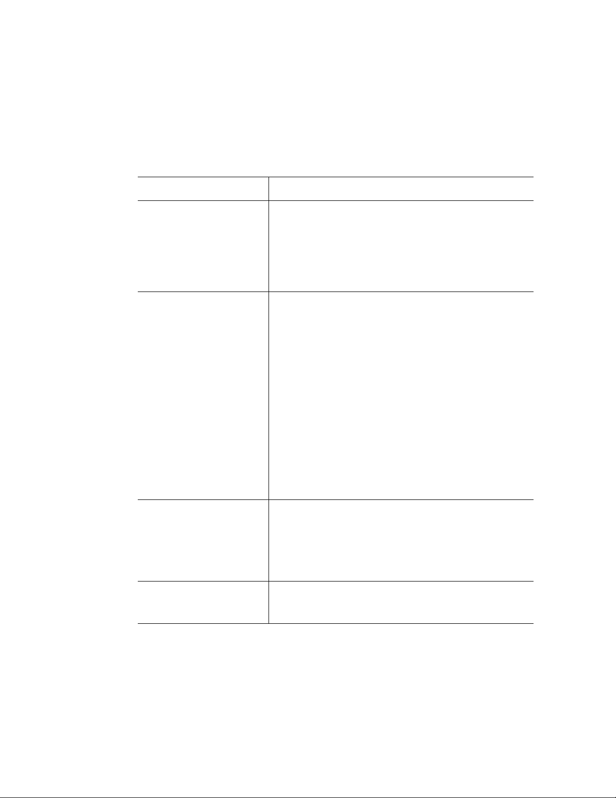
Chassis Front
Figure 2 shows the front view of the chassis with the snap-on bezel in place. The bezel
provides access to the optical drive, front panel controls, and the hot-swap hard drives.
The bezel must be removed to access the memory boxes.
B
C
A
D E F G
A. Front Panel, see “Front Panel” E. Memory box 1
B. Optical Drive F. Memory box 2
AF001082
C. Hard Drives, HDD0 - HDD7 from left to right G. Memory box 3
D. Memory box 0
Figure 2. Chassis Front View
4 Intel® Server System SR9000MK4U Product Guide
Page 27
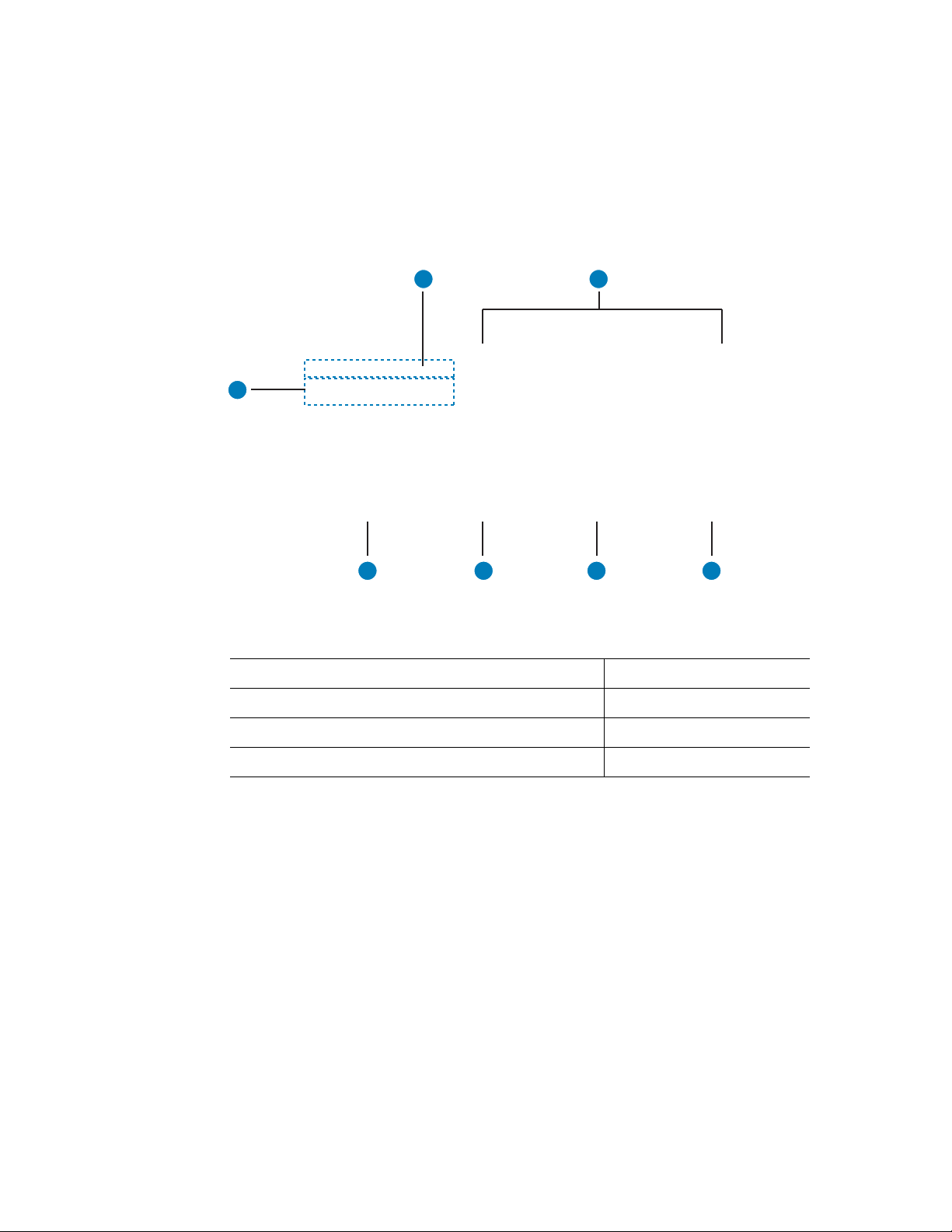
Front Panel
The front panel is located below the slimline optical drive on the left-side of the chassis
front. The front panel provides buttons and status indicator LEDs. Figure 3 shows the
control buttons and status indicators on the front panel.
A
A. USB Port 0, USB 1.1. The port is shut down in
case of an over-current. To recover, power
down server and then power it back on.
B. USB Port 1, USB 1.1. The port is shut down in
case of an over-current. To recover, power
down server and then power it back on.
C. Power button and power LED.
– Green on: ACPI S0 state.
– Green blink: System is powering down.
– LED off: ACPI S5 state.
For information about power the system on and off,
see “Powering the System On and Off” on page x.
C
B
F. Identification button and blue ID LED. Button toggles
state of LED between on and off.
E
D
G
F
I
H
AF001083
– Blue on: Identifies server.
– Blue blink: CMOS being cleared or FWH recovery
in process. For instructions on how to clear the
CMOS, see “Clearing the CMOS” on page 140.
– Off: System not identified, CMOS not being
cleared, FWH recovery not in process.
G. Power fault LED:
– Orange on: Critical, non-recoverable power fault
detected.
– Orange blink: Non-critical power fault detected.
– Off: No power fault detected.
H. Cooling fault LED:
– Orange on: Critical non-recoverable cooling fault
detected.
– Orange blink: Non-critical cooling fault detected.
– Off: No cooling fault detected by the BMC.
D. Reset button: Resets the system. I. General fault LED:
– Orange on: Critical, non-recoverable fault other
than power or cooling fault detected.
– Orange blink: Non-critical fault other than power or
cooling fault detected.
– Off: No general fault detected.
E. System diagnostic interrupt (SDINT) button:
Asserts INIT to system.
Figure 3. Front Panel Controls and Indicators
Intel® Server System SR9000MK4U Product Guide 5
Page 28

Optical Drive Bay
The slim-line optical drive (DVD-ROM / CD-ROM drive) is inserted from the front of the
optical drive bay. The system power must be turned off to remove or install this drive.
Note: Intel validates specific DVD-ROM / CD-ROM drives. See the Intel
SR9000MK4U Tested Hardware and Operating System List” for a list of these drives
available.
AF001084
Figure 4. Optical Drive Bracket with Drive Installed
®
Server System
Hot-swap Hard Drive Bay
The hot-swap hard drive carrier, shown in Figure 5 is designed to support 15,000-RPM or
slower SAS3G technology hard drives.
AF001085
Figure 5. Hard Drive Carrier
6 Intel® Server System SR9000MK4U Product Guide
Page 29
Notes:
The hard drive carriers contain light-pipes that allow dual-color LED indicators to display
through the bezel. The hard drive status is described in Table 4.
Table 4. SAS Hard Drive LED Details
LED Color State Description
Green On Activity
4 Hz blink Locate
1 Hz blink Rebuild
Red On Error
Red / Green / Off Blink Hard drive insert
Power on reset with or without hard drive
• To test the hard drive LEDs, do the following:
— Install a hard drive.
— Power on the system.
— Watch for the LED status to change. The red LED should be on for 0.5 seconds,
then the green turns on and remains on.
• Intel validates specific hard drive types in the Server System SR9000MK4U. See the
®
Server System SR9000MK4U T ested Hardware and Operating System List for
Intel
a list of the drives supported.
Intel® Server System SR9000MK4U Product Guide 7
Page 30
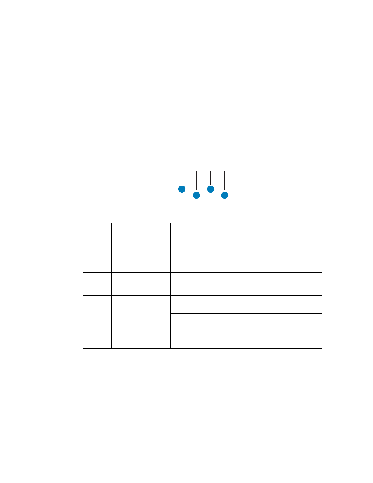
Memory Box
In memory mirror mode, memory box 0 is paired with memory box 1. Memory box 2 is
paired with memory box 3. When mirroring mode is used, either of the memory boxes
with a pair can be hot-swapped.
Figure 6 shows the front view of the memory box.
A
Callout LED LED State Description
A Memory Box Mirror
LED
B Memory Box Power
LED
C Memory Box
Attention LED
D No LED N/A Hot-swap button. Press this button to initiate
Green on The memory box is operating in mirror
Off The memory box is not operating in mirror
Green on The memory box is powered on.
Off The memory box is powered off.
Orange on An error has been detected in the memory
Off No error has been detected on the memory
C
B
D
mode.
mode.
box.
box or the memory box is powered off.
a hot-swap process.
AF001086
Figure 6. Memory Box Front View
8 Intel® Server System SR9000MK4U Product Guide
Page 31

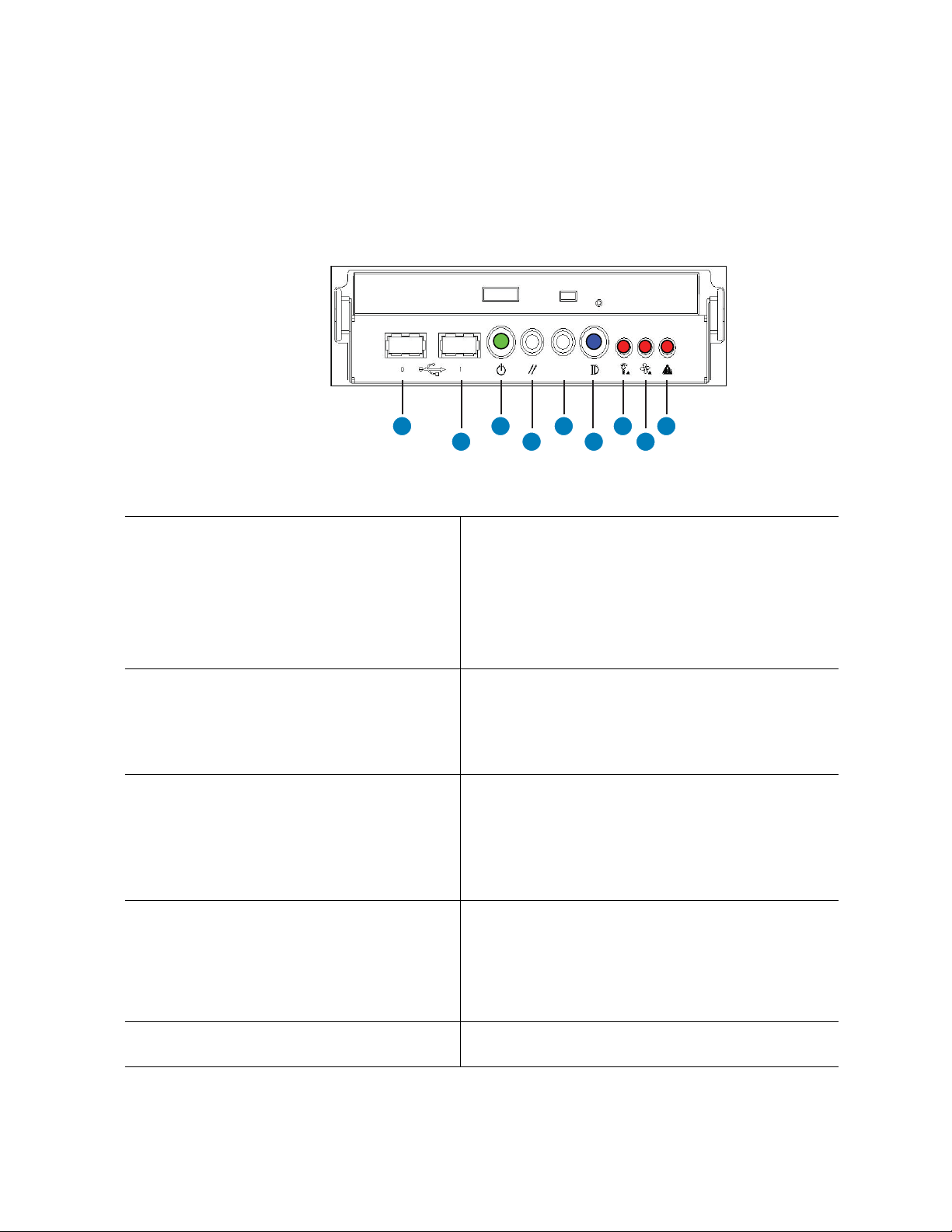
Chassis Rear
Figure 7 shows the features found on the rear panel.
A B
D
C
A AC input power connectors
B AC input power connectors
C PCI Slots All slots support hot-plug PCI add-in cards. From left to right:
– Slot 6: 133 MHz, 64-bit PCI-X*, full length
– Slot 5: PCI-Express* x 16, half length
– Slot 4: PCI-Express x 8, half length
– Slot 3: 133 MHz, 64-bit PCI-X, half length
– Slot 2: PCI-Express x 16, half length
– Slot 1: PCI-Express x 8, half length
F
E
H
G
I
AF001087
D Dual Gb Ethernet ports RJ45 connectors. See Table 5 for LED information.
– GbE1: top
– GbE0: bottom
E 100 Mb Ethernet ports RJ45 connectors. See Table 5 for LED information.
– Ether0: left. Management LAN port
– Ether1: right. KVM LAN port
F Four USB ports 4-pin connectors:
– Top left: RUSB3
– Bottom left: RUSB2
– Top right: RUSB1
– Bottom right: RUSB0
G Video port Standard VGA compatible, 15-pin connector
H Serial port 9-pin RS-232 connector
I Identification Button Toggles chassis ID LED on/off.
Figure 7. Chassis Rear View
Intel® Server System SR9000MK4U Product Guide 9
Page 32

Table 5. NIC LEDs
Item LED Color State Description
Gigabit Ether, ports GbE1
and GbE0
Fast Ether (Management
LAN, KVM LAN), ports
Ether0 and Ether1
ACT/LNK
(right LED)
SPEED
(left LED)
ACT/LNK
(right LED)
SPEED
(left LED)
Green On Link
Green Blink Active
None Off No link
Yellow On 1000
Green On 100
None Off 10
Green On Link
Green Blink Active
None Off No link
Green On 100
None Off 10
10 Intel® Server System SR9000MK4U Product Guide
Page 33

Internal Layout
The following diagram shows the location of components inside of the server system.
B C
A
E
D
F
BB
AA
Z
Y
X
W
V
U
T
S
R
Q
MNOP
A. System Fan 2 K. PCI-Express, x16, Slot 5 U. Memory Box 2
AF001089
G
H
I
J
K
L
B. System Fan 0 L. PCI-X, Slot 6 V. DIMM Sockets
C. System Fan 1 M. Processor 2 W. DIMM Sockets
D. System Fan 3 N. Processor 3 X. Memory Box 1
E. Processor 0 O. System Fan 5 Y. DIMM Sockets
F. Processor 1 P. System Fan 4 Z. DIMM Sockets
G. PCI-Express, x8, Slot 1 Q. DIMM Sockets AA. Memory Box 0
H. PCI Express, x 16, Slot 2 R. Memory Box 3 BB. DIMM Sockets
I. PCI-X, Slot 3 S. DIMM Sockets
J. PCI-Express, x8, Slot 4 T. DIMM Sockets
Figure 8. Open System, Top View
Intel® Server System SR9000MK4U Product Guide 11
Page 34

Internal Chassis Features
Power Supply Subsystem
The 12 V hot-swap power supply modules are rated at 1390 W over an input range of 200
- 240 VAC, and at 990 W over an input range of 100-127 VAC.
The power supply module has two outputs, that is, +12 V and +5 Vsb. The standby
voltages +5 Vsb is active anytime AC input power is applied to the power supply.
The power supply module is connected to the main board directly and can be used in 1+1
redundant mode.
Note: Two power supplies must be installed and plugged in when a 110 V outlet is used. Hot-
swapping and redundancy are not available under this condition.
One power supply can be used when it is connected to a 220 VAC outlet. Under this
condition, redundancy is available and a power supply can be hot-swapped if necessary.
Table 6. 1390 W Power Supply Configuration
AC Input
200-240 V 9.5 A Supported Supported Restriction of loading is
100-127 V 12 A Not supported Not supported Restriction of loading is
Current
See Note
Redundancy Hot-swap Remarks
Note: This value is applied to one power supply.
needed. Two power
supplies must be
installed to enable
redundancy and hotswap.
needed. Two power
supplies must be
installed top operate the
server system.
12 Intel® Server System SR9000MK4U Product Guide
Page 35

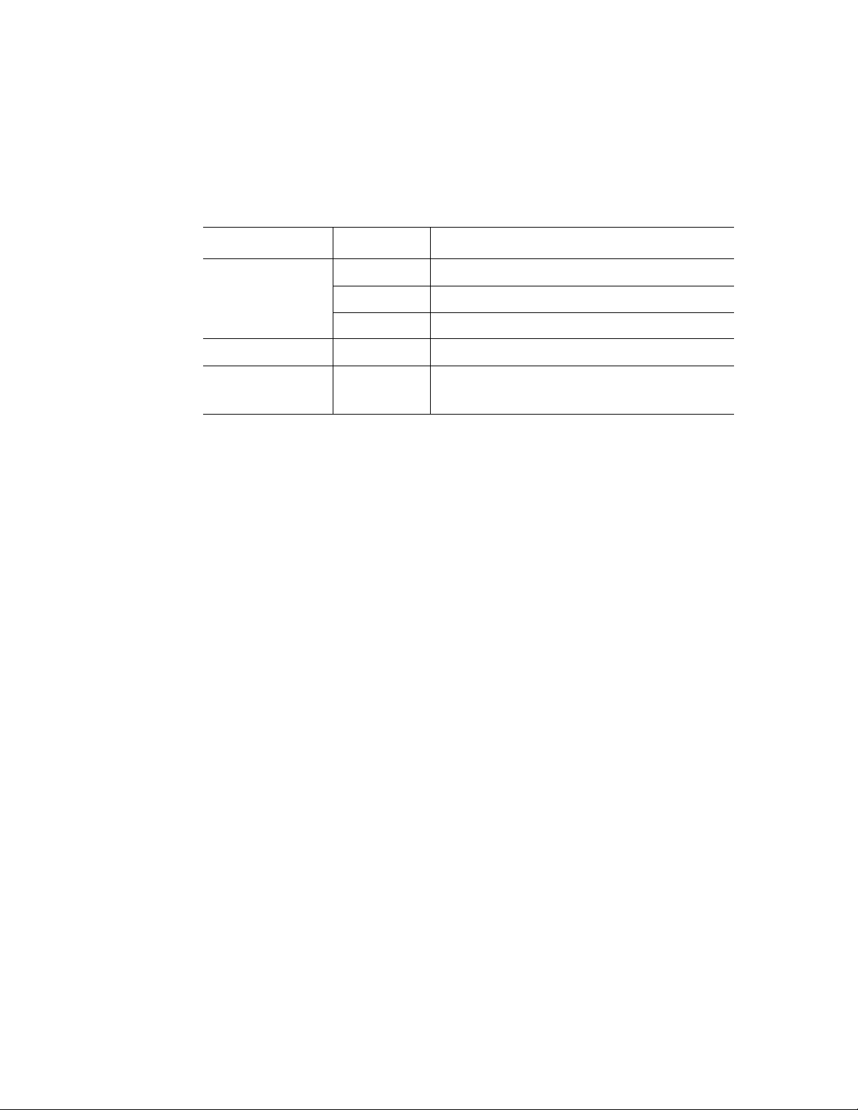
Each power supply contains three LEDs on the top surface. The LED locations and
descriptions are as follows.
!
A B C
AF001090
A Input Good LED Indicates input power is good, when this
LED (green) is on.
B DC Output Good LED Indicates output power is good, when this
C Fault LED Indicates a fault with the power supply.
LED (green) is on.
Figure 9. Power Supply Indicators
Intel® Server System SR9000MK4U Product Guide 13
Page 36

Cooling Subsystem
The cabinet inlets have hot-swappable, 5+1 redundant fans for coolin g.
120 mm x 38 mm fans are used. They provide enough airflow to cool the system
components, processors, memory and chipset, even if one of the six fans fails. The fans
are located across the center of the cabinet. The hard drives and DVD-ROM drive are
cooled by suction. Components on main board, processor and chipset are cooled by the air
flow through the air duct.
The power supply module has non-redundant fans in it for cooling the power supply.
Caution: The chassis top cover must be installed for proper system cooling. Additionally, cooling
fans must be hot-swapped within two minutes. This time period applies only to the time
that the cooling fan is physically removed, not from the time of failure.
A
AF001091
A Cooling Fan LED Indicates fan is working normally when LED (green) is on
Indicates fan has a fault when LED is off.
Figure 10. Cooling Fan Indicator
14 Intel® Server System SR9000MK4U Product Guide
Page 37

PCI Card Slot
A B
AF001092
A Power LED Indicates PCI slot status is active.
B Attention LED and lens switch Indicates error, when this yellow LED is on. The lens
switch is used for hot installs / removals.
Figure 11. PCI Card Slot Indicator
Intel® Server System SR9000MK4U Product Guide 15
Page 38

16 Intel® Server System SR9000MK4U Product Guide
Page 39

2 Intel
Board Set Overview
The board set for the Intel® Server System SR9000MK4U consists of one main board,
four memory box cards (installed in the memory boxes), one hard drive backplane and one
front panel board. The block diagram of Intel
follows. The connection points between the main board and the front panel board are
shown by the green circled numbers.
®
Server System SR9000MK4U
®
Server System SR9000MK4U is as
#0
MC
MC
MC
MC
Main BoardMain Memory Board x4
Intel
Itanium 2
Itanium2
VHDM
VHDM
Processor
Intel
Itanium 2
Itanium2
Processor
MVR
MVR
MVR
MVR
#1
MC
MC
VHDM
MC
MC
#2
MC
MC
MC
MC
VHDM
VHDM
VHDM
Node
Node
Controller
Controller
Intel
Itanium 2
Itanium2
Processor
Intel
Itanium2
Itanium 2
Processor
MVR
MVR
MVR
MVR
#3
MC
MC
MC
MC
VHDM
VHDM
Node
Node
Controller
Controller
1
H8S/
H8S/
2166
2166
SIO
SIO
Intel
Intel
ESB-2
ESB-2
Panel
Connector
FPGA
FPGA
Intel
Intel
6700
6700
PXH
PXH
ATI
ATI
ES1000
ES1000
Slot0
KVM
KVM
Intel
Intel
82551QM
82551QM
Intel
Intel
82563
82563
40pin IDE
Connector
LSI Logic
LSI Logic
SAS
SAS
1068
1068
SFF-8484
Connector
PCI-e x8 slot
PCI-e x8 slot
PCI-e x16 slot
PCI-e x16 slot
PCI-X 133MHz slot
PCI-X 133MHz slot
PCI-e x8 slot
PCI-e x8 slot
PCI-e x16 slot
PCI-e x16 slot
PCI-X 133MHz slot
PCI-X 133MHz slot
COM port
VGA port
USB2/3 port
USB0/1 port
100MbE
LAN1 port
100MbE
LAN0 port
GbE LAN0/1
2
3
Slot1
Slot2
Slot3
Slot4
Slot5
Slot6
USB4/5 port
Front
Panel
Board
LED&
Switch
DVDROM
Drive
HDD#0
HDD#1
HDD#2
HDD#3
HDD#4
HDD#5
HDD#6
HDD#7
HDD
Backplane
Panel
Connector
40pin IDE
Connector
SFF-8484
Connector
SFF-8484
Connector
SFF-8482
Connector x8
1
2
3
To/From
Add-on
SAS PCI Card
AF001093
Figure 12. Block Diagram
17
Page 40

Main Board
Main Board
C15 C16
C11
FAN0
VHDM0
C12
C17 C18
FAN2
VHDM1
P10
C13
VHDM2
C14
VHDM3
C29
C19
FAN4
C25
P12
XDP
P13
Battery
PANEL
P11
Super
H8S
IO
FPGA
FAN1
FAN3
C20
FAN5
C26
PANEL PWR
C1
C2
P1
C3
C4
P2
Processor
Socket0
Processor
Socket1
NDC0
Processor
Socket2
Processor
Socket3
NDC1
C21
PS0
C22
PS1
C27
C30
MVR0/1
P3
ESB2
P9
C23
C7
P4
7SEG
P21
PXH
C10
SAS
SAS
KVM
P7
VGA
VRAM
P8
C24
ATA
IPMB
C32
C33
DEBUG
C5
PCI slot1
C6
PCI slot2
PCI slot3
C8
PCI slot4
C9
PCI slot5
PCI slot6
MVR2/3
P14
P6
LAN
E4
C28
P15
P16
P17
P18
P19
P20
ID SW
E1
COM
VGA
E2
USB2/3
E3
USB0/1
LAN1
E6
(KVM)
LAN0
E5
(Management)
GbE
LAN0/1
P5
LAN
P28
P22
P23
P29
P24
P30
P25
P31
P26
P32
P27
P33
AF001095
Figure 13. Main Board Layout
18 Intel® Server System SR9000MK4U Product Guide
Page 41

Table 7. Main Board Components
Board
Location
P1/P2 Hitachi* NDC Node Controller:
Component Description
• One Front Side Bus
– 533/667 MHz FSB support
– Two processors per bus
• Four interfaces connecting to the memory
controller
• Three x8 PCI Express* ports
• Proprietary high-speed interface to link between
two node controllers
• Optimized design for 667 MHz FSB to achieve
low memory access latency
• Broadcast-based cache coherence control to
minimize snoop transaction
P3 Intel
P4 Intel
®
ESB2 Enterprise South Bridge
®
6700PXH 64-bit PCI Hub:
• PCI bridging functions between the PCI Express
interface and the PCI Bus
• One PCI Express* interface (primary bus)
• x8 and x4 modes operation
• Maximum 2 GB/s in each direction
simultaneously
• Two PCI / PCI-X* bus interfaces (secondary bus)
• PCI 2.3-compliant
• PCI-X 1.0b-compliant
P5 Intel
®
82563 Physical Layer Transceiver (PHY) component
designed for 10/100/1000 Mbps operation:
• IEEE 802.3 (10BASE-T), IEEE 802.3u
(100BASE-TX), IEEE 802.3ab (1000BASE-T)
• Dual port
®
P6 Intel
82551QM Fast Ethernet PCI bus controller:
• IEEE 802.3 (10BASE-T), IEEE 802.3u
(100BASE-TX), 32-bit PCI bus master interface
P7 ATI* ES1000 Graphics processing unit:
• 2D graphics accelerator
• PCI bus interface (PCI 2.2 compliant, 33 MHz)
P8 VRAM 64 MB VRAM for ATI ES1000:
• Max resolution: Up to 1280 x 1024, 85 Hz
• Max color depth: Up to 32 bpp true color
Intel® Server System SR9000MK4U Product Guide 19
Page 42

Table 7. Main Board Components
Board
Location
P9 LSI Logic* SAS1068 PCI-X* to 3 Gb/s 8-port SAS controller. Four of the
Component Description
eight ports are used.
• 1.5 and 3 Gb/s SAS and SATA data transfer
rates per port, full duplex
• 64-bit, 133 MHz PCI-X host interface
• Integrated RAID support
– Fusion-MPT* architecture
– Integrated Striping* technology (RAID0)
– Integrated Mirroring* technology (RAID1)
P10 H8S/2166 Baseboard management controller (BMC)
P11 SIO Super I/O
P12 FPGA Management interface and shared memory extension
bridge
P13 Battery CMOS backup
P14 ID SW This is a button combined with an LED. It can be used
to identify a particular system and is useful in locating
a particular system among many. The first time the
button is pressed, the LED turns on. If the button is
pressed again, the LED will blink and then turn off.
P15-P20 PCI-X* / PCI-
Express* slot
Attention
Switch
P21 7SEG LED Indicates POST code
P22-P27 PCI-X/e slot
Power LED LED to indicate an
P28-P33 PCI-X / PCI-Express*
Attention LED LED to indicate an
Switch used for hot
swapping PCI cards.
active PCI slot status
slot
error other PCI card
slot condition. See
“PCI Card Slot” on
page 15.
20 Intel® Server System SR9000MK4U Product Guide
Page 43
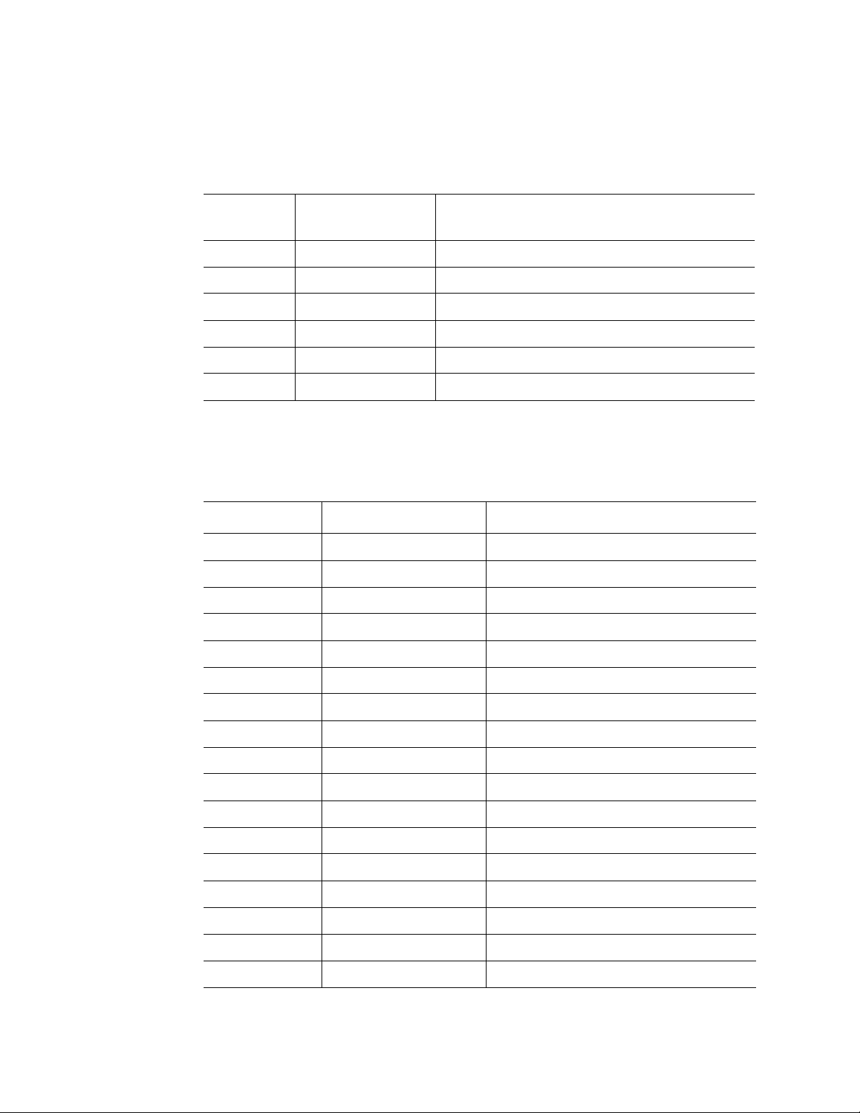
Table 8. Main Board External I/O Connectors
Board
Location
E1 Serial RS232C D-sub 9-pin serial port
E2 VGA Mini D-sub 15-pin video port
E3 USB 0/1/2/3 USB Type A port x4
E4 GbE LAN 0/1 RJ45 LAN port x2
E5 100 MbE LAN RJ45 LAN port x1
E6 100 MbE LAN RJ45 LAN port x1 (for KVM)
Connector Description
Table 9. Main Board Internal I/O Connectors
Board Location Connector Description
C1~C4 CPU 0/1/2/3 mPGA700 ZIF sockets
C5/C8 PCI slot 1/4 x8 PCI-Express* slots
C6/C9 PCI slot 2/5 x16 PCI-Express slots
C7/C10 PCI slot 3/6 64-bit 133 MHz PCI-X* slots
C11~C14 VHDM 0/1/2/3
C15~C20 FAN 0/1/2/3/4/5
C21/C22 PS 0/1
C23 SAS SFF-8484 (SAS internal x4 connector)
C24 ATA 40-pin IDE connector
C25 PNL
C26 PNLPW
C27/C28 MVR0/1, MVR2/3
C29 XDP
C30 KVM
C31 SATA
C32 IPMB
C33 DEBUG
Intel® Server System SR9000MK4U Product Guide 21
Page 44

Configuration Restrictions
Table 10. Configuration Restrictions
AC Input Configuration
Maximum Number of
Number
Input
Voltage
100-127 2 No 4 0 2 No
200-240 2 Yes 4 0 2 No
of
Mounted
AC/DC
AC/DC
Redundancy
Processors
®
Intel®
Itanium
042 No
®
533 MTS
2,
Intel
Itanium
667 MTS
®
PCI-Express*
Graphics Card
2,
(75 W)
Configuration
Restriction
0 4 Restricted, see
note below
1No 4 0 2 No
0 4 Restricted, see
note below
Yes
Yes
Note: When one or two 75-watt PCI-Express* graphics cards are installed, the system will
supply power for that slot during the power-on sequence or hot-add process. Then, on
finding the violation of the configuration restriction, the system halts the power supply to
the slot. In the case of a hot-add, since the operating system cannot identify the hot-added
card as 75 watt, the 75-watt card cannot be hot added in restricted cases.
22 Intel® Server System SR9000MK4U Product Guide
Page 45

Processor Configurations
Figure 14 shows the top view of main board, indicating the processor locations. Table 11
shows the allowed processor configurations. Choose your configuration from Table 11
and install each processor in the locations indicated by Figure 14.
A
B
D
AF001100
C
A. Processor 1 C. Processor 3
B. Processor 2 D. Processor 4
Figure 14. Processor Locations
Table 11. Supported Processor Configuration
Configuration
Number
1 Installed Not Installed Not Installed Not Installed
2 Installed Installed Not Installed Not Installed
3 Installed Not Installed Installed Not Installed
4 Installed Installed Installed Not Installed
5 Installed Installed Installed Installed
Processor
Socket 0
Processor
Socket 1
Processor
Socket 2
Processor
Socket 3
Intel® Server System SR9000MK4U Product Guide 23
Page 46

Memory Box Card
Mirror LED
Power
LED
Attention
LED
Hot Swap SW
c4
c3
c2
c1
P3
P4
P5
P6
c5
c6
c7
c8
JD0A0
JD0A1
JD0B0
JD0B1
JD2B1
JD2B0
JD2A1
JD2A0
c9
P1
P2
MC2
MC0
Figure 15. Memory Box Card Layout
Table 12. Memory Box Card Components
Board Location Component Description
P1/P2 MC0/2 Memory Controller
P3 Mirror LED See “Memory Box” on page 8.
P4 Attention LED See “Memory Box” on page 8.
P5 Power LED See “Memory Box” on page 8.
VHDM
AF001096
P6 Hot Swap Button
Table 13. Memory Box Card Connectors
Board Location Connector Description
C1 JD0B1 240-pin DDR2 DIMM socket (MC0 channel A)
C2 JD0B0 240-pin DDR2 DIMM socket (MC0 channel A)
C3 JD0A1 240-pin DDR2 DIMM socket (MC0 channel B)
C4 JD0A0 240-pin DDR2 DIMM socket (MC0 channel B)
C5 JD2B1 240-pin DDR2 DIMM socket (MC1 channel A)
C6 JD2B0 240-pin DDR2 DIMM socket (MC1 channel A)
C7 JD2A1 240-pin DDR2 DIMM socket (MC1 channel B)
24 Intel® Server System SR9000MK4U Product Guide
Page 47

Board Location Connector Description
C8 JD2A0 240-pin DDR2 DIMM socket (MC1 channel B)
C9 VHDM
DIMM Configurations
Figure 16 shows the DIMM locations within each memory box. One memory box houses
either four or eight DIMMs. For a four-DIMM configuration, the DIMMs should be
installed into locations JD0A1, JD0B1, JD2B1 and JD2A1.
Table 13. Memory Box Card Connectors
JD0A0
JD0A1
JD0B0
JD0B1
JD2B1
JD2B0
JD2A1
JD2A0
Figure 16. DIMM Locations (Top View of Memory Box)
AF001101
Intel® Server System SR9000MK4U Product Guide 25
Page 48

Three memory modes are available. The memory mode is selected depending on the
number of memory boxes that are connected to one NDC chip, and whether the BIOS is
configured for mirror mode. See the following table for information.
Table 14. Memory Operational Modes
Memory
Operational
Mode
Single One MMR is connected to
Double Two MMRs are connected
Mirror Two MMRs are connected
Description
an NDC. No redundancy.
Throughput of data
transfer is half that of
Double mode.
to an NDC. No
redundancy. Throughput
of data transfer is double
that of Single mode.
to an NDC and the same
data is stored in these two
MMR. Two MMRs are
running like a mirror of
each other and provide
redundancy. Throughput
of data transfer is half that
of Double mode.
Number of
MMR
Connected
to One NDC
1 Disabled or
2 Disabled No
2 Enabled Yes
BIOS Set-Up
of Mirror
Mode
Enabled
Redundancy
No
and Hot-
swap
Support
The following figures show the installation order and upgrade path for DIMMs, and the
applicable mode for each configuration. In these figures, solid lines indicate installed
memory boxes; dotted lines indicated locations of empty memory box sockets. Black
boxes indicate installed DIMMs.
The first set of figures (1-A, 2-A, 3-A, 4-A) represent configurations in which four
DIMMs are installed in each installed memory box. The paths to the right of the figures
marked 'W', 'X', 'Y', and 'Z' show the upgrade to fully populated memory boxes (eight
DIMMs in each memory box). These fully populated configurations are shown in the
second set of figures (1-B, 2-B, 3-B, 4-B).
For example, configuration 1-A has only one MMR with four DIMMs installed, so only
single mode is applicable. This configuration can be connected to three paths for upgrade,
that is, to 2-A, 3-A. and 1-B.
In the paths to 2-A and 3-A, another memory box is needed. 2-A has a higher memory
bandwidth than 3-A, because 2-A can use two NDC chips effectively. In 3-A, processors
connected to the NDC linked to the MC with DIMMs installed can access all of the
system memory with the shortest access time. Therefore, in some specialized situations, 3A has a performance advantage to 2-A, such as in a two-socket installation.
26 Intel® Server System SR9000MK4U Product Guide
Page 49

In the path to 1-B no new memory box is needed and therefore has a lower cost for
capacity addition.
Memory mirroring is applicable to 3-A, but not to 2-A nor 1-B.
1MMR/4DIMM
NDC NDC
-
MC MC
MMR
Upgra de Pat h
2-A
NDC NDC
MC MC MC MC
MMR
Upgra de Pat h
-
NDC NDC
MC MC MC MC
MMR
Upgrade Path
Upgrade Path
Single Mode
Single Mode 2MMR/8DIMM
Double Mode Mirror Mode 2MMR/8DIMM
W
Upgrade Path
X
Upgrade Path
Y
Upgrade Path
-
NDC NDC
MC MC MC MC MC MC MC
MMR MMR
Double Mode Mirror Mode 4MMR/16DIMM
MC
Z
Upgrade Path
AF001102
Intel® Server System SR9000MK4U Product Guide 27
Page 50

Upgrade Path
1MMR/8DIMM
Upgrade Path
3
W
MC MC
-
NDC NDC
Single Mode
MMR
NDC NDC
MC MC MC MC
X
MMR
NDC NDC
MC MC MC MC
Y
Upgrade Path
MMR
NDC NDC
MC MC MC MC MC MC MC
Z
Upgrade Path
MMR MMR
Upgra de Pat h
Upgra de Pat h
2-B
-B
4-B
Upgrade Path
MMR
Upgrade Path
Upgrade Path
Single Mode 2MMR/16DIMM
Double Mode Mirror Mode 2MMR/16DIMM
Double Mode Mirror Mode 4MMR/24 DIMM
MC
5-B
NDC NDC
MC MC MC MC MC MC MC
Z
Upgrade Path
MMR MMR
Double Mode Mirror Mode 4MMR/32DIMM
MC
AF001103
Figure 17. Memory Upgrade Path
28 Intel® Server System SR9000MK4U Product Guide
Page 51

Hard Drive Backplane
SAS1
SAS0
PNL
Figure 18. Hard Drive Backplane Top View
ATA
PNLP
AF001097
IDLED1 IDLED 2 I D L E D 3
HM
IDLED0
IDLED4
IDLED5
IDLED6
IDLED7
HDD0
HDD1
HDD2
HDD3
HDD5
HDD6
HDD4
HDD7
AF001098
Figure 19. Hard Drive Backplane Bottom View
Table 15. Hard Drive Backplane Connectors
Board Location Connector Description
C0 HDD0/1/2/3 SFF-8482 (SAS internal x1 connector)
C1 HDD4/5/6/7. See note
below
C2 SAS0 SFF-8484 (SAS internal x4 connector)
C3 SAS1. See note below SFF-8484 (SAS internal x4 connector)
SFF-8482 (SAS internal x1 connector)
C4 ATA 40-pin IDE connector
C5 PNL Panel connector
C6 PNLPW Panel power
Note: Available when additional SAS PCI card is inserted into PCI slot.
Intel® Server System SR9000MK4U Product Guide 29
Page 52

Hard Drive Population
The on-board SAS controller is connected to four of the eight hard drives, drives 0
through 3. Hard drives 4 through 7 require the addition of an add-in SAS card.
Front Panel Board
USB4
USB5
DVD
Power Switch / Power LED
Reset Switch
SDINT Switch
Identification Switch / ID LED
Power Fault LED
Cooling Fault LED
General Fault LED
tch / Power LED
HM
HM
AF001099
Figure 20. Front Panel Board Layout
Table 16. Front Panel Board Components
Board
Location
P1 Power Button, Power LED See “Front Panel” on page 5.
P2 Reset Button See “Front Panel” on page 5.
P3 SDINT (System Diagnostic Interrupt) Button See “Front Panel” on page 5.
Component Description
P4 Identification Switch, Identification LED See “Front Panel” on page 5.
P5 Power Fault LED See “Front Panel” on page 5.
P6 Cooling Fault LED See “Front Panel” on page 5.
P7 General Fault LED See “Front Panel” on page 5.
30 Intel® Server System SR9000MK4U Product Guide
Page 53

Table 17. Front Panel Board Connectors
Board Location Connector Description
C1 HM
C2 DVD
C3 USB4/5 USB Type A port x2
Intel® Server System SR9000MK4U Product Guide 31
Page 54

32 Intel® Server System SR9000MK4U Product Guide
Page 55

3 Installing and Removing
Components
To complete many of the installation or removal procedures in this chapter, you will need
to first install or remove other components. For example, to remove the PCI card divider,
you first need to remove the chassis cover, the power supplies, the power supply box, the
CPU1/CPU2 MVR cable, the KVM card, and all add-in cards. This guide will direct you
to each installation / removal section as is necessary to accomplish your final goal. This
means you may need to change pages several times to move from one procedure to the
next.
Cautions:
• Installing and replacing optional components inside the server is to be performed
only by trained personnel.
• Before following any of the procedures in this chapter, review all of the safety
instructions located in “Safety Information” on page 193.
• Unless you are performing a hot swap function for hot swap instructions are
provided, you must turn off your system and disconnect all power plugs before
beginning any procedure in this chapter.
• Do not subject the hard drive to vibrations or impacts. Drive failure may result from
vibrations or impacts.
• Before hot-swapping, be sure to completely understand the procedures written in
this manual.
Tools Needed
The following tools are needed to install or remove the hardware described in this chapter.
• Phillips* screwdriver #2
• Flathead screwdriver 5.5 x 75
• 2.5 mm hex driver
• Torx-15* driver
• Cotton gloves
• Antistatic wrist strap
33
Page 56

Installing and Removing the Front Bezel
You will need to remove the front bezel to perform the following operations:
• To install or remove a memory box
• To install or remove DIMMs
• To install or remove an optical drive
• To install or remove the front control panel
• To install or remove the hard drive backplane
• To install or remove the mounting plate
Removing the Front Bezel
1. Insert your finger(s) into the hole at the left side of the front bezel. See letter “A” in
the figure below.
2. Pull the bezel firmly.
A
Figure 21. Removing the Front Bezel
34 Intel® Server System SR9000MK4U Product Guide
Page 57

Installing the Front Bezel
1. Set the left or right side of the bezel into place at the front of the system.
2. Set the opposite side of the bezel into place.
3. Push firmly until the bezel snaps into place.
Figure 22. Installing the Front Bezel
AF001105
Intel® Server System SR9000MK4U Product Guide 35
Page 58

Installing and Removing the Top Cover
You will need to remove the top cover to perform the following operations:
• To install or remove a power supply
• To install or remove the power supply box
• To install or remove the power supply support
• To install or remove a fan
• To install or remove the fan box
• To install or remove a PCI card
• To install or remove the PCI card divider
• To install or remove the KVM card
• To install or remove the air flow guide
• To install or remove the hard drive backplane cover
• To install or remove the hard drive backplane
• To install or remove a processor
• To install or remove the mounting plate
Removing the Top Cover
1. Pull up on the two levers on the top cover. See letter “A” in the following figure.
2. Lift the cover from the system. See letter “B” in the figure.
Figure 23. Removing the Top Cover
A
B
AF001106
36 Intel® Server System SR9000MK4U Product Guide
Page 59

Installing the Top Cover
1. Place the front edge of the cover on the chassis.
2. Lower the rear of the cover into place, as shown by letter “A” in the figure below.
A
AF001107
Figure 24. Installing the Top Cover
Installing and Removing a Hard Drive
Cautions:
You will need to remove the hard drive(s) or the hard drive carriers to perform the
following operations:
• To replace a hard drive
• To install or remove the hard drive backplane
• To install or remove the mounting plate
• Handle the hard drive carefully. Inappropriate handling may result in hard drive
failure.
• Always create backup copies of important data on the hard disk. If the hard drive
fails, all data stored on it will be lost.
Intel® Server System SR9000MK4U Product Guide 37
Page 60

Installing a Hard Drive
Caution: Before performing the procedures written in this chapter, except for when hot-swapping,
be sure to turn off the system and disconnect all power plugs.
1. Push down on the button at the top of the drive carrier lever. See letter “A” in the
figure below.
2. While holding down the button, pull forward on the lever to open it. See letter “B”.
3. Continue pulling on the lever to slide the carrier from the system.
B
A
AF001108
Figure 25. Pulling Down on the Hard Drive Carrier Lever
4. Remove the four screws at the sides of the hard drive carrier. Two screws are at
each side of the carrier. See letter “A” in the figure below.
Note: Do not remove the metal EMI shield from the carrier.
5. Set the hard drive into the hard drive carrier, with the connections extending from
the rear of the carrier.
6. Install the four screws that you removed in step 4, two on each side of the carrier.
See letter “A” in the figure below.
38 Intel® Server System SR9000MK4U Product Guide
Page 61

A
AF001111
Figure 26. Mounting a Hard Drive
7. Open the hard drive carrier lever if it is closed.
8. Slide the hard drive carrier into the bay along the guide rail. See the figure below.
9. When the lower part of the lever touches the bay, push the lever closed while
pushing the carrier into the system.
AF001112
Figure 27. Installing a Hard Drive
Intel® Server System SR9000MK4U Product Guide 39
Page 62

Removing a Hard Drive
Cautions:
• Before performing the procedures in this chapter, except for when hot-swapping,
turn off the system and disconnect all power plugs.
• If you attempt to replace a faulty hard drive using inappropriate procedures may
result in data corruption.
• Before replacing any hard drives, back up all data.
• Replacing a hard drive that has not failed may corrupt data on the drive. Remove
only the failed drive.
• Do not subject the hard drive to vibrations or impacts. Drive failure may result from
vibrations or impact.
1. Push down on the button at the top of the drive carrier lever. See letter “A” in the
figure below.
2. Pull forward on the lever to open it. See letter “B”.
3. Continue pulling on the lever to slide the carrier from the system.
B
Figure 28. Pulling Down on the Hard Drive Carrier Lever
A
AF001108
40 Intel® Server System SR9000MK4U Product Guide
Page 63

4. Remove the four screws at the sides of the hard drive carrier. Two screws are at
each side of the carrier. See letter “A” in the figure below.
Note: Do not remove the metal EMI shield from the carrier.
5. Lift the drive from the carrier.
A
AF001111
Figure 29. Unmounting a Hard Drive
6. Determine your next course of action and refer to the appropriate steps:
— If you are installing a replacement hard drive, see “Installing a Hard Drive” on
page 38, beginning with step 5.
— If you are following these steps as part of another procedure, return to that
procedure.
— If you have completed working with the drive carrier, slide it back into the
chassis opening.
Intel® Server System SR9000MK4U Product Guide 41
Page 64

Hot-swapping a Hard Drive
Note: Remove only the failed drive. Removing the wrong drive could cause the system to
malfunction or may cause data loss.
1. Use the LED indicators at the top of the hard drive carriers to determine which
drive has failed. The red LED indicates the failed hard drive. See letter “A” in the
figure below.
Figure 30. Hard Drive LED Indicators
A
AF001115
2. Install the new hard drive. See “Installing a Hard Drive” on page 38.
Installing and Removing a Memory Box
Your system was shipped with two memory boxes installed and two memory box filler
panels installed. Before you can use your server system, each memory box must be
populated with either four or eight DIMMs.
Note: The system will not boot if a memory box is installed with no DIMMs in it.
You will need to remove the memory box to perform the following operations:
• To replace a memory box
• To install or remove DIMMs
• To install or remove the mounting plate
42 Intel® Server System SR9000MK4U Product Guide
Page 65

Installing a Memory Box
To perform this procedure, you will first need to remove the front bezel. The steps below
will direct you to the instructions on removing the front bezel at the appropriate location
in the step sequence.
Caution: Before performing the procedures in this chapter, except for when hot-swapping, turn off
the system and disconnect all power plugs.
1. Remove the front bezel. For instructions, see “Removing the Front Bezel” on
page 34.
2. If a filler panel is installed, pull up on the memory box filler panel release lever to
unlock it. See letter “A” in the figure below.
A
AF001116
Figure 31. Removing the Memory Box Filler Panel
3. While holding the release lever up, pull the memory box filler panel from the
system. Save the filler panel for future use.
4. If necessary, install DIMMs into the memory box. For instructions, see “Installing
DIMMs” on page 49.
5. Pull out on the metal front edge of the memory box.
Intel® Server System SR9000MK4U Product Guide 43
Page 66

6. Carefully slide the memory box into the bay. When the memory box is correctly
inserted the notches at the sides of the metal cover align with the edge of the bay.
See the figure below.
AF001118
Figure 32. Installing the Memory Box
7. Close the metal cover. See letter “A” in the following figure. If the metal cover does
not close easily, the memory box is not positioned correctly in the bay. Slide the
memory box out slightly and try again to close the cover.
8. Lift the memory box eject lever into the locked position. Make sure the lever is
fully closed. See letter “B” in the following figure.
A
B
AF001119
Figure 33. Memory Box Installed and Locked into Place
9. Determine your next course of action and refer to the appropriate steps:
— If you are following these steps to complete another procedure, return to those
steps.
— If you have finished with all steps and procedures, install the front bezel. For
instructions, see “Installing the Front Bezel” on page 35.
44 Intel® Server System SR9000MK4U Product Guide
Page 67

Removing a Memory Box
To perform this procedure, you will first need to remove the front bezel. The steps below
will direct you to the instructions on removing the front bezel at the appropriate location
in the step sequence.
Caution: Before performing the procedures in this chapter, except for when hot-swapping, turn off
the system and disconnect all power plugs.
1. Remove the front bezel. For instructions, see “Removing the Front Bezel” on
page 34.
2. Push down on the memory box release lever to unlock the memory box. See letter
“A” in the figure below.
3. Fully open the metal cover on the memory box. See letter “B” in the figure.
4. Carefully pull the memory box from the system and place it on a clean, static-free
surface.
B
A
AF001120
Figure 34. Removing the Memory Box
5. Determine your next course of action and refer to the appropriate steps:
— If you are following these steps as part of another procedure, return to that
procedure.
— If a memory box will not be re-installed, slide a memory box filler panel into the
open memory box slot until it clicks into place.
6. Install the front bezel. For instructions, see “Installing the Front Bezel” on page 35.
Intel® Server System SR9000MK4U Product Guide 45
Page 68

Hot-swapping a Memory Box
To perform this procedure, you will first need to remove the front bezel. The steps below
will direct you to the instructions on removing the front bezel at the appropriate location
in the step sequence.
Cautions:
• Before hot-swapping the memory box, confirm that hot-swapping can be performed
by checking the following:
— Memory Mirroring” is set to “Enable” as shown in “Memory Screen” on
page 148.
— DIMMs are config ur ed as either of the configuration patterns 3A, 4A, 3B, 4B, or
5B described as “Mirror Mode” in “DIMM Configurations” on page 25.
— The green mirror LEDs are turned on. See Figure 35.
• Wear an antistatic wrist strap.
• Be sure to remove/replace only the intended memory box. If the memory box has
failed, then the Attention LED for the failed memory box will be orange.
• Follow the hot-swap sequence described below. Failure to follow the steps may
result in a system malfunction.
The following diagram shows the LEDs and components on the front of the memory box.
A
B
C
D
E
A. Mirror LED (green) D. Hot-swap button
B. Power LED (green) E. Eject lever
C. Attention LED (orange)
Figure 35. Memory Box Front View
46 Intel® Server System SR9000MK4U Product Guide
AF001123
Page 69

1. Remove the front bezel. For instructions, see “Removing the Front Bezel” on
page 34.
2. Push the hot-swap button for the memory box you want to remove. To cancel the
operation, push the button again within five seconds.
3. The power LED blinks; wait for all memory box LEDs to turn off. If the status LED
does stop blinking, shut down the system to replace the memory box.
4. Remove the memory box. For instructions, see “Removing a Memory Box” on
page 45. Then return to these steps.
Warning: The memory box will be very hot. Do not touch any components on it.
5. Wait approximately 10 minutes to allow the memory box to cool before touching
any components on it.
6. Install, remove, or replace the DIMMs as necessary. See “Installing and Removing
DIMMs” on page 48.
7. Install the memory box. For instructions, see “Installing a Memory Box” on
page 43, beginning with step 5. Then return to these steps.
8. Push the hot-swap button for the memory box. If the attention LED turns on after
pushing the button, see if the DIMM configuration is the same or different as the
configuration before you performed the hot-swap operation.
— If the configuration is different, repeat steps 2 through step 6. Configure the
DIMMs. Continue this series of steps with step 7 above.
— If the configuration is the same, a fault exists in DIMM or in the memory box.
Repeat these steps, using different DIMMs or a different memory box.
The power LED blinks, and then turns on solidly. The mirror LED blinks and then
it turns on solidly. Memory mirroring functions resume after the mirror LED is on
solidly.
9. If the power and memory LED do not return to solid on, power off the system to
remove the memory box and repeat the installation.
10. Install the front bezel. For instructions, see “Installing the Front Bezel” on page 35.
Intel® Server System SR9000MK4U Product Guide 47
Page 70
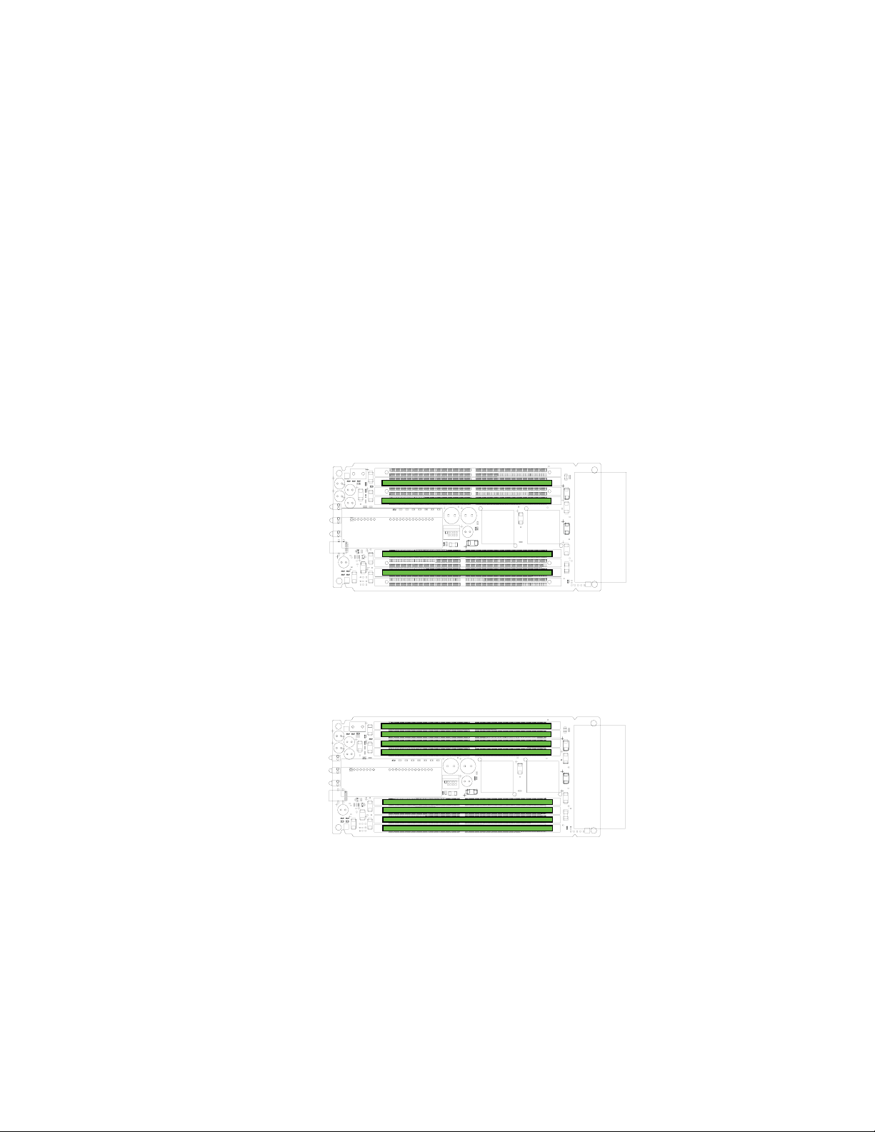
Installing and Removing DIMMs
DIMM Installation Guidelines
Each installed memory box must have either four or eight DIMMs installed, as shown
below.
• Four DIMM installation: Install DIMMs in JD0B1, JD0A1, JD2B1, JD2A1
• Eight DIMM installation: DIMMs installed in each socket
Note: When facing the front or r ear of the memory box, the four sockets at the left ar e positioned
in the opposite direction from the four sockets at the right. Be sure to reverse the DIMMs
accordingly. Make sure the notches at the center of the DIMMs line up correctly with the
tabs in the center of the sockets.
AF001124
Figure 36. Four-DIMM Installation Pattern
AF001125
Figure 37. Eight-DIMM Installation Pattern
Note: The system will not boot if a memory box is installed with no DIMMs in it.
48 Intel® Server System SR9000MK4U Product Guide
Page 71

Installing DIMMs
To perform this procedure, you will first need to remove:
• The front bezel
• The memory box
The steps below will direct you to the instructions for these procedures at the appropriate
location in the step sequence.
Cautions:
• Before performing the procedures in this chapter, except for when hot-swapping,
turn off the system and disconnect all power plugs.
• Be aware when removing the memory box that removed parts are hot. Wait
approximately 10 minutes after removing the parts before handling them.
• Wear cotton gloves when handling DIMMs.
• Take precautions against static.
1. Remove the memory box. For instructions, see “Removing a Memory Box” on
page 45.
2. Push out on the clips at each end of the DIMM socket(s) to open the DIMM
sockets.
3. Insert the DIMMs so that the tab in the center of DIMM socket fits the notch of
DIMM.
Note: When facing the front or rear of the memory box, the four sockets at the left
are positioned in the opposite direction from the four sockets at the right. Be
sure to r everse the DIMMs accor dingly. Make sure the notches at the center of
the DIMMs line up correctly with the tabs in the center of the sockets.
4. Push down firmly to seat the DIMM into the socket. The clips on each end of the
socket will close.
Caution:
✧ Do not apply force to peripheral parts when inserting a DIMM.
✧ DIMMs may be difficult to insert. Do not rock the DIMM back and forth when
inserting it. Instead, apply steady, firm pressure.
5. Make sure the DIMMs are inserted correctly and the clips are fully closed.
6. Install the memory box. For instructions, see “Installing a Memory Box” on
page 43, beginning with step 6.
Intel® Server System SR9000MK4U Product Guide 49
Page 72

Removing DIMMs
To perform this procedure, you will first need to remove:
• The front bezel
• The memory box
The steps below will direct you to the instructions for these procedures at the appropriate
location in the step sequence.
Cautions:
• Before performing the procedures in this chapter, except for when hot-swapping,
turn off the system and disconnect all power plugs.
• Be aware when removing the memory box that removed parts are hot. Wait
approximately 10 minutes after removing the parts before handling them.
• Wear cotton gloves when handling DIMM.
• Take measures against static.
1. Remove the memory box. For instructions, see “Removing a Memory Box” on
page 45.
2. Push out on the clips at each end of the DIMM socket(s) to open them.
Note: It may be difficult to open the clips on the memory socket. Do not apply force
to peripheral parts when opening the clips.
Caution: Be careful not to touch peripheral parts when opening the clips for the
DIMM socket.
3. Pull the DIMM from the socket.
Caution: Be careful not to apply force to peripheral parts when removing a DIMM.
4. Install the memory box. For instructions, see “Installing a Memory Box” on
page 43, beginning with step 6.
Note: The system will not boot if a memory box is installed with no DIMMs in it.
50 Intel® Server System SR9000MK4U Product Guide
Page 73

Installing and Removing an Optical Drive
Installing an Optical Drive
To perform this procedure, you will first need to remove the front bezel. The steps below
will direct you to the instructions on removing the front bezel at the appropriate location
in the step sequence.
Note: Before performing the procedures in this section, turn off the system and disconnect all
power plugs.
1. Remove the front bezel. For instructions, see “Removing the Front Bezel” on
page 34.
2. Locate the optical drive location at the left side of the system. See the following
figure.
Figure 38. Locating the Optical Drive Installation Position
3. Push the lever on the side of the optical drive or the filler panel to remove it from
the system. Keep the filler panel for future use.
A
AF001129
Figure 39. Removing the Optical Drive Filler Panel
Intel® Server System SR9000MK4U Product Guide 51
Page 74

4. With the rear of the optical drive facing you, as shown by letter “A” below, install
the left side of the bracket onto the drive. The bracket (letter “B” in the figure) has a
small tab that fits into a dimple in the drive sheetmetal.
5. Roll the right side of the bracket down until it clicks into place.
A B
AF001117
Figure 40. Attaching the Optical Drive to the Bracket
6. Slide the optical drive assembly into the system until it clicks into place. See letter
“A” in the figure below.
A
AF001130
Figure 41. Installing of Optical Drive
7. Install the front bezel. For instructions, see “Installing the Front Bezel” on page 35.
52 Intel® Server System SR9000MK4U Product Guide
Page 75

Removing the Optical Drive
To perform this procedure, you will first need to remove the front bezel. The steps below
will direct you to the instructions on removing the front bezel at the appropriate location
in the step sequence.
Note: Before performing the procedures in this section, turn off the system and disconnect all
power plugs.
1. Remove the front bezel. For instructions, see “Removing the Front Bezel” on
page 34.
2. Locate the optical drive location at the left side of the system. See the following
figure.
Figure 42. Locating the Optical Drive Installation Position
3. Push the lever on the optical drive to remove it from the system.
A
Figure 43. Removing Optical Drive from Server
AF001129
Intel® Server System SR9000MK4U Product Guide 53
Page 76

4. Push the lever to release the drive from the bracket. See letter “A” in the figure
below.
A
AF001132
Figure 44. Removing the Optical Drive from the Bracket
5. If you are not replacing the drive, insert the optical drive filler into the server until it
clicks into place.
Caution: Insert a blank/filler into any unused slot. Uncovered slots may reduce the cooling effect of
the system.
6. Install the front bezel. For instructions, see “Installing the Front Bezel” on page 35.
54 Intel® Server System SR9000MK4U Product Guide
Page 77

Installing and Removing a Fan
You will need to remove the fan(s) to perform the following operations:
• To replace a fan
• To install or remove the fan box
• To install or remove the hard drive backplane
• To install or remove the mounting plate
Installing a Fan
To perform this procedure, you will first need to remove the top cover. The steps below
will direct you to the instructions to remove the top cover at the appropriate location in the
step sequence.
Before operating the procedures written in this chapter, except when hot-swapping, be
sure to turn off the system and then disconnect all power plugs.
1. Remove the top cover. For inst ructions, see “Removing the Top Cover” on page 36.
2. Locate the fan area of the system. See the following figure.
AF001133
Figure 45. Locating the Fans
Intel® Server System SR9000MK4U Product Guide 55
Page 78

3. Note the fan orientation in the figure below to make sure you insert the fan
correctly. Insert the fan into the bay.
AF001134
Figure 46. Installing a Fan
4. Determine your next course of action and refer to the appropriate steps:
— If you are following these steps as part of another procedure, return to that
procedure.
— Install the top cover. For instructions, see “Installing the Top Cover” on page 37.
56 Intel® Server System SR9000MK4U Product Guide
Page 79

Removing a Fan
To perform this procedure, you will first need to remove the top cover. The steps below
will direct you to the instructions to remove the top cover at the appropriate location in the
step sequence.
Caution: Before performing the procedures in this chapter, except for when hot-swapping, turn off
the system and disconnect all power plugs.
1. Remove the top cover. For inst ructions, see “Removing the Top Cover” on page 36.
2. Locate the fan area in the system. See the following figure.
AF001133
Figure 47. Locating the Fans
3. Insert your thumb and a finger into the rounded and square holes at the top of the
fan.
4. Lift the fan from the system.
AF001135
Figure 48. Removing a Fan
Intel® Server System SR9000MK4U Product Guide 57
Page 80

5. Determine your next course of action and refer to the appropriate steps:
— If you have removed a fan to replace a failed fan, see “Installing a Fan” on
page 55.
— If you are following these steps as part of another procedure, return to that
procedure.
Hot-swapping a Fan
To perform this procedure, you will first need to remove the top cover. The steps below
will direct you to the instructions to remove the top cover at the appropriate location in the
step sequence.
Cautions:
• Replace the fan within two minutes of removing the failed fan. If a fan bay remains
unpopulated for more than two minutes, the cooling system could fail.
• Remove only the failed component. Removing the incorrect component could cause
the system to malfunction.
1. Remove the top cover. For instructions, see “Removing t he Top Cover” on page 36.
2. Confirm that the cooling fan LED is turned off. This indicates the fan has a fault.
See letter “A” in the following figure.
A
AF001137
Figure 49. Fan Fault LED
3. Remove the fan. See “Removing a Fan” on page 57.
4. Install the new fan. See “Installing a Fan” on page 55.
5. Install the top cover. For instructions, see “Installing the Top Cover” on page 37.
58 Intel® Server System SR9000MK4U Product Guide
Page 81

Installing and Removing a PCI Card
You will need to remove the PCI card(s) to perform the following operations:
• To replace a PCI card
• To install or remove the PCI card divider
• To install or remove the fan box
• To install or remove the air flow guide
• To install or remove the hard drive backplane
• To install or remove the mounting plate
• To install or remove a processor
Installing a PCI Card
To perform this procedure, you will first need to remove the top cover. The steps below
will direct you to the instructions to remove the top cover at the appropriate location in the
step sequence.
Cautions:
• Before performing the procedur es in this section, except for when hot-swapping turn
off the system and then disconnect all power plugs.
• Use caution when touching the add-in card to avoid touching components on the
card.
1. Remove the top cover. For inst ructions, see “Removing the Top Cover” on page 36.
2. Locate the PCI slot area. See the following figure.
3. Lift the PCI caution plate. See letter “A” in the figure below.
A
AF001138
Figure 50. Opening the PCI Caution Plate
Intel® Server System SR9000MK4U Product Guide 59
Page 82

4. Push the PCI card lock firmly to unlock the card or the slot cover. See the figure
below.
AF001139
Figure 51. Unlocking a PCI Card Lock
5. Remove the PCI slot cover. See the figure below. Keep the slot cover for future use.
AF001140
Figure 52. Removing a PCI Slot Cover
60 Intel® Server System SR9000MK4U Product Guide
Page 83

6. Install the PCI card. See Figure 54.
— For a short-length card, insert the PCI card firmly into the slot.
— For a full-length card: Insert the PCI card into the slot. The end of the card at the
front side of the chassis must inserted and locked into place in the PCI tail lock.
See Figure 53.
Note: Full-length cards can be installed only into PCI slot 6.
AF001136
Figure 53. PCI Tail Lock
TP001141
Figure 54. Installing a PCI Card
Intel® Server System SR9000MK4U Product Guide 61
Page 84

7. Pull the PCI card lock firmly until it clicks into place. See the figure below.
AF001142
Figure 55. Locking a PCI Card into Place
8. Lower the PCI caution plate. See letter “A” in the figure below.
A
AF001144
Figure 56. Closing the PCI Caution Plate
9. Attach any cables necessary for the card you installed. See your add-in card
documentation for information and instructions.
10. Determine your next course of action and refer to the appropriate steps:
— If you are following these steps as part of another procedure, return to that
procedure.
— Install the top cover. For instructions, see “Installing the Top Cover” on page 37.
62 Intel® Server System SR9000MK4U Product Guide
Page 85

Removing a PCI Card
To perform this procedure, you will first need to remove the top cover. The steps below
will direct you to the instructions to remove the top cover at the appropriate location in the
step sequence.
Cautions:
• Before performing the procedur es in this section, except for when hot-swapping turn
off the system and then disconnect all power plugs.
• Use caution when installing the add-in card to avoid touching components on the
card.
1. Remove the top cover. For inst ructions, see “Removing the Top Cover” on page 36.
2. Raise the PCI caution plate. See letter “A” in the figure below.
A
Figure 57. Opening a PCI Caution Plate
AF001138
Intel® Server System SR9000MK4U Product Guide 63
Page 86

3. Push the PCI card lock firmly to unlock the PCI card. See the figure below.
AF001139
Figure 58. Unlocking a PCI Card Lock
4. Remove the PCI card and place it on a clean, static-free surface.
— For a short-length card, pull the PCI card from the slot.
— For a full-length card: Pull back on the PCI tail lock to release the PCI card. See
the figure below. While holding the PCI tail lock back, pull out the PCI card.
AF001143
Figure 59. Releasing the PCI Card from the Tail Lock
64 Intel® Server System SR9000MK4U Product Guide
Page 87

5. Insert the slot cover over the opening at the rear of the chassis.
Note: Be sure to insert a slot cover over any unused slot. An uncovered slot may
affect the cooling system.
AF001147
Figure 60. Installing a PCI Slot Cover
6. Pull the PCI card lock until it locks into place. See the figure below.
AF001142
Figure 61. Locking a PCI Card or Slot Cover into Place
Intel® Server System SR9000MK4U Product Guide 65
Page 88

7. Close the PCI caution plate. See the figure below.
A
AF001144
Figure 62. Closing the PCI Caution Plate
8. Determine your next course of action and refer to the appropriate steps:
— If you have removed a PCI card and need to replace it, see “Install ing a PCI
Card” on page 59.
— If you are following these steps as part of another procedure, return to that
procedure.
— If you are done working inside your server system, install the top cover. For
instructions, see “Installing the Top Cover” on page 37.
66 Intel® Server System SR9000MK4U Product Guide
Page 89

Hot-Plugging a PCI Card
To perform this procedure, you will first need to remove the top cover. The steps below
will direct you to the instructions to remove the top cover at the appropriate location in the
step sequence.
Caution: Use caution when installing the add-in card to avoid touching components on the card.
1. Remove the top cover. For inst ructions, see “Removing the Top Cover” on page 36.
2. Press the lens switch button PCI card you want to replace. Hold the button down for
5 or more seconds. See letter “B” in the figure below. To cancel this operation,
press the lens switch again within five seconds of the first press.
3. Only if PCI card is installed in the slot: Confirm that the power LED state changes
from green to blinking to off. See letter “A” in the figure. This step does not apply
if a slot cover is installed instead of a PCI card.
A
B
AF001149
Figure 63. Locating the Lens Switch and PCI Card LED
4. Remove the PCI card or slot cover. See “Removing a PCI Card” on page 63,
following steps 2 through 4. Then return to these steps.
5. Insert the new PCI card. For instructions, see “Installing a PCI Card” on page 59,
following steps 6 through 9. Then return to these steps.
6. For five or more seconds, press the lens switch for the PCI card you want to
replace. If you need to cancel this operation, press the button again within five
seconds of the first press. This step is not necessary if a slot cover is installed
instead of an add-in card.
7. Confirm that the power LED state changes from off to blinking to green. When the
slot cover is inserted instead of PCI card, skip this operation.
8. Install the top cover. For instructions, see “Installing the Top Cover” on page 37.
Intel® Server System SR9000MK4U Product Guide 67
Page 90

Installing and Removing a Power Supply
Your system was shipped to you with two power supplies installed. Both power supplies
must be installed and plugged in when a 110 V outlet is used. Hot-swapping is not
available under this condition. One power supply can be used when it is connected to a
220 V outlet. Under this condition, a power supply can be hot-swapped if necessary.
The instructions below describe removing a power supply filler panel. The power supply
filler panel would be used only if the power supply is connected to a 220 V outlet. If a
power supply is removed and not replaced, a filler panel must be installed into the empty
opening.
You will need to remove the power supplies to perform the following operations:
• To replace a power supply
• To install or remove the power supply box
• To install or remove the power supply support
• To install or remove the fan box
• To install or remove the PCI card divider
• To install or remove the air flow guide
• To install or remove the hard drive backplane
• To install or remove the mounting plate
• To install or remove a processor
Warning: The power supply module has a high-voltage area in it. Do not open the power supply. It
may result in electric shock or equipment failure.
Installing a Power Supply
To perform this procedure, you will first need to remove the top cover. The steps below
will direct you to the instructions to remove the top cover at the appropriate location in the
step sequence.
Note: Before performing the procedures in this section, except for when hot-swapping, turn off
the system and then disconnect all power plugs.
1. Remove the top cover. For instructions, see “Removing t he Top Cover” on page 36.
2. If a power supply filler panel is installed:
— Loosen the captive screw on the power supply filler. See letter “A” in the figure
below.
— Lift the power supply filler from the system. See letter “B” in the figure. Save
the filler for future use.
68 Intel® Server System SR9000MK4U Product Guide
Page 91

A
B
AF001150
Figure 64. Removing a Power Supply Filler
3. Simultaneously push the two levers on the top of the power supply slightly outward
and then raise them to unlock the power supply. See letter “A” in the following
figure.
4. Use the handle on the power supply to lower it into the system. See letter “B” in the
figure.
Caution: Do not lift the power supply by the levers. Lift the power supply only by the handle.
A
A
B
AF001152
Figure 65. Installing a Power Supply
Intel® Server System SR9000MK4U Product Guide 69
Page 92

5. Push down the two levers on the top of the power supply to lock it into place. See
letter “A” in the figure below.
6. Lower the handle on the power supply. See letter “B” in the figure.
A
B
A
AF001153
Figure 66. Locking the Power Supply into Place
7. Determine your next course of action and refer to the appropriate steps:
— If you are following these steps as part of another procedure, return to that
procedure.
— If you are done working inside your server system, install the top cover. For
instructions, see “Installing the Top Cover” on page 37.
Removing a Power Supply
To perform this procedure, you will first need to remove the top cover. The steps below
will direct you to the instructions to remove the top cover at the appropriate location in the
step sequence.
Cautions:
• Before performing the procedures in this section, except for when hot-swapping,
turn off the system and then disconnect all power plugs.
• Care must be taken when you re place the power supply module; the cover or handle
is hot when the system is powered on.
• Before removing the power supply, pull up two levers to release the connector
between power supply and main board.
70 Intel® Server System SR9000MK4U Product Guide
Page 93

1. Remove the top cover. For inst ructions, see “Removing the Top Cover” on page 36.
2. Simultaneously push the two levers on the top of the power supply slightly outward
and then raise them to unlock the power supply. See letter “A” in the figure below.
A
A
AF001154
Figure 67. Opening the Power Supply Levers
3. Use the handle to lift the power supply from the system. See the figure below.
Caution: Do not use the levers to lift or move the power supply. Only use the handle to lift the
power supply.
AF001155
Figure 68. Removing the Power Supply
Intel® Server System SR9000MK4U Product Guide 71
Page 94

4. If you are not installing a replacement power supply, insert the power supply filler
panel (see letter “A” in the figure below) and tighten the captive screw to attach it
to the open slot. See letter “B” in the figure.
Caution: Install a filler panel into any unused slot. An open slot will affect the system cooling.
B
A
AF001157
Figure 69. Installing a Power Supply Filler
5. Determine your next course of action and refer to the appropriate steps:
— If you have removed your power supply and need to replace it, see “Installing a
Power Supply” on page 68.
— If you are following these steps as part of another procedure, return to that
procedure.
— If you are done working inside your server system, install the top cover. For
instructions, see “Installing the Top Cover” on page 37.
72 Intel® Server System SR9000MK4U Product Guide
Page 95

Hot-swapping a Power Supply
To perform this procedure, you will first need to remove the top cover. The steps below
will direct you to the instructions to remove the top cover at the appropriate location in the
step sequence.
Cautions:
• Be sure to remove only the failed component. Removing of an incorrect component
could cause system to malfunction.
• A power supply cannot be hot swapped in the following configurations:
— When input voltage is 100-127 V.
— When only one power supply is installed.
1. Remove the top cover. For inst ructions, see “Removing the Top Cover” on page 36.
2. Check the LED indicators on the power supplies. The red LED indicates the failed
power supply.
!
A B C
AF001090
A Input Good LED Indicates input power is good, when this green LED is on.
B DC Output Good LED Indicates output power is good, when this green LED is on.
C Fault LED Indicates the power supply has a fault.
Figure 70. Power Supply LED Indicators
Intel® Server System SR9000MK4U Product Guide 73
Page 96

3. Disconnect the power cable from the power supply you want to replace.
4. Remove the power supply. For instructions, see “Removing a Power Supply” on
page 70. Return to these steps after removing the power supply.
5. Install the new power supply. For instructions, see “Installing a Power Supply” on
page 68.
6. Install the top cover. For instructions, see “Installing the Top Cover” on page 37.
Installing and Removing the Front Control Panel and Optical Drive Assembly
Removing the Front Control Panel and Optical Drive Assembly
Before beginning these steps, power down your server system and unplug all AC power
cords.
To perform this procedure, you will first need to remove the front bezel. The steps below
will direct you to the instructions to remove the front bezel at the appropriate location in
the step sequence.
1. Remove the front bezel. For instructions, see “Removing the Front Bezel” on
page 34.
2. Push and hold the levers on each sides of the front control panel / DVD-ROM drive
assembly. See letter “A” in the figure below.
3. Pull out the front control panel / optical drive assembly. See letter “B” in the figure.
B
A
AF001211
Figure 71. Removing the Front Control Panel and Optical Drive Assembly
74 Intel® Server System SR9000MK4U Product Guide
Page 97

4. Determine your next course of action and refer to the appropriate steps:
— If you have removed your front control panel / optical drive assembly and need
to replace it, see “Installing the Front Control Panel and Optical Drive
Assembly” on page 75.
— If you are following these steps as part of another procedure, return to that
procedure.
Installing the Front Control Panel and Optical Drive Assembly
These steps assume you have removed your front control panel and optical drive
assembly , your server system is currently powered down, and your front bezel is removed.
1. Slide the front control panel / optical drive assembly in through the front of the
chassis as shown in the left figure below.
2. Push the assembly firmly until it clicks into place.
AF001212
Figure 72. Installing the Front Control Panel and Optical Drive Assembly
3. Determine your next course of action and refer to the appropriate steps:
— If you are following these steps as part of another procedure, return to that
procedure.
— Install the front bezel. For instructions, see “Installing the Front Bezel” on
page 35.
Intel® Server System SR9000MK4U Product Guide 75
Page 98

Installing and Removing the Power Supply Box
Before beginning these steps, power down your server system and unplug all AC power
cords.
You will need to remove the power supply box to perform the following operations:
• To install or remove the power supply support
• To install or remove the fan box
• To install or remove the PCI card divider
• To install or remove the air flow guide
• To install or remove the hard drive backplane
• To install or remove the mounting plate
• To install or remove a processor
Removing the Power Supply Box
To perform this procedure, you first need to remove:
• The top cover. For instructions, see “Removing the Top Cover” on page 36.
• All installed power supplies. For instructions, see “Removing a Power Supply” on
page 70.
• The power supply filler panel, if one is installed. For instructions, see “Installing a
Power Supply” on page 68. Follow step 2 only.
Remove these components, in order, before beginning the steps below.
The steps below do not guide you through reinstalling the components you are removing
or disconnecting in this step sequence. These steps assume you are removing the power
supply box to either replace it, or to access another component. After completing these
steps, continue with the steps that directed you to this section, or follow the steps under
“Installing the Power Supply Box” on page 80 to replace your power supply box.
76 Intel® Server System SR9000MK4U Product Guide
Page 99

1. Disconnect the CPU1 / CPU2 MVR cable from the main board. To disconnect this
cable, press and hold the latch on the cable connector while pulling on the
connector. See the figure below to locate the MVR cable connection.
AF001431
Figure 73. Locating the CPU1 / CPU2 MVR Connection
2. Disconnect the IDE cable from the main board. See letter “A” in the figure below.
3. Disconnect the SAS4I cable from the main board. To disconnect the cable, press
both ends of the cable to be unlocked, and then disconnect it. See letter “B” in the
figure.
4. Remove the cables from the clips at the top of the power supply box. See letters
“C” and “D” in the figure.
C
D
A
B
AF001432
Figure 74. Disconnecting the IDE and SATA Cables
Intel® Server System SR9000MK4U Product Guide 77
Page 100

5. Loosen the two captive screws on the exterior of the system. One screw is on each
side of the system. See the figure below.
AF001213
Figure 75. Loosening the Exterior Captive Screws
6. Loosen the two captive screws inside the system. See the figure below.
AF001214
Figure 76. Loosening the Interior Captive Screws
78 Intel® Server System SR9000MK4U Product Guide
 Loading...