

Page 1
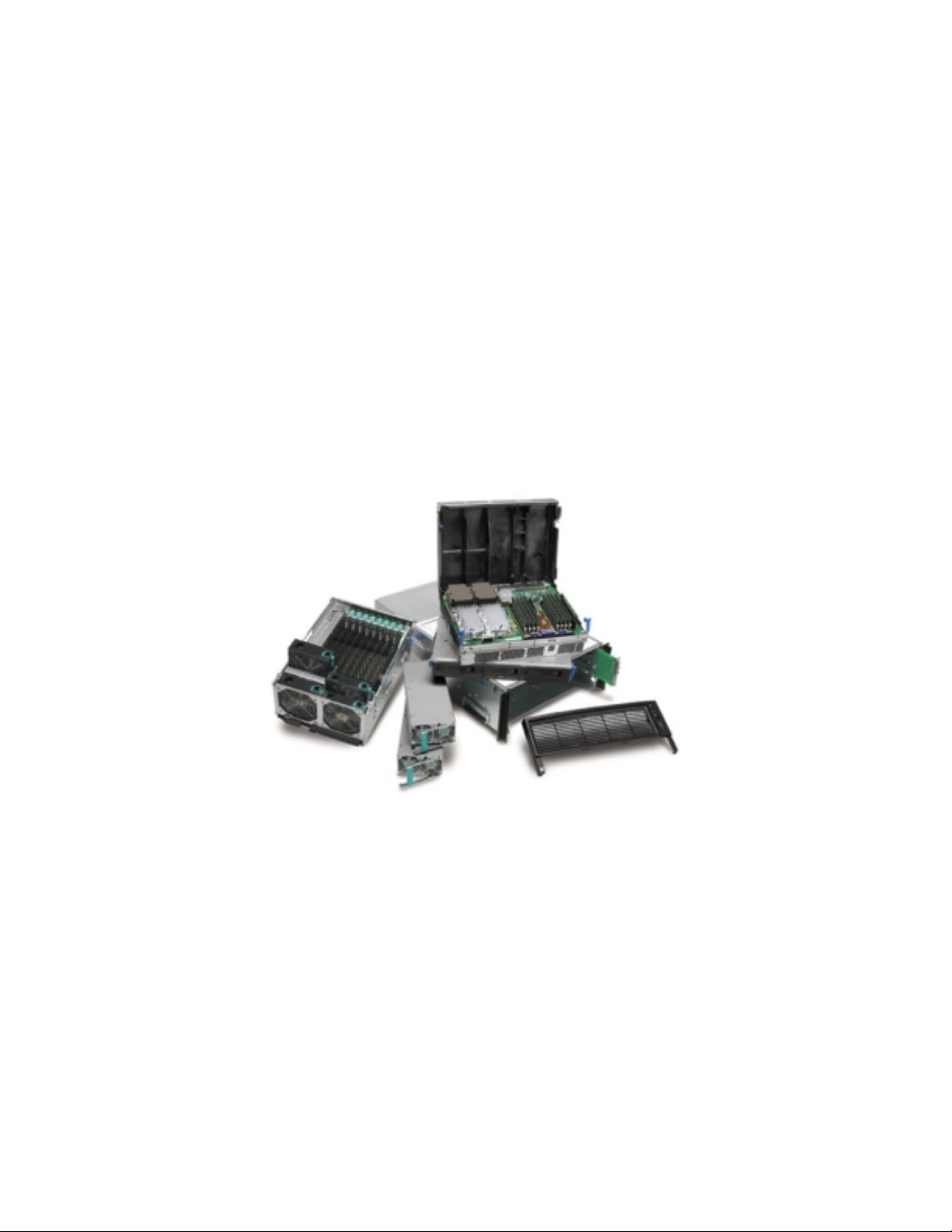
SR870BN4
Configuration Guide
A quick reference guide to assist customers in ordering the components
necessary to configure the SR870BN4 platform
Revision 1.6
October 18, 2004
INFORMATION IN THIS DOCUMENT IS PROVIDED IN CONNECTION WITH INTEL® PRODUCTS. NO
LICENSE, EXPRESS OR IMPLIED, BY ESTOPPEL OR OTHERWISE, TO ANY INTELLECTUAL PROPERTY
RIGHTS IS GRANTED BY THIS DOCUMENT. EXCEPT AS PROVIDED IN INTEL'S TERMS AND
CONDITIONS OF SALE FOR SUCH PRODUCTS, INTEL ASSUMES NO LIABILITY WHATSOEVER, AND
INTEL DISCLAIMS ANY EXPRESS OR IMPLIED WARRANTY, RELATING TO SALE AND/OR USE OF
INTEL PRODUCTS INCLUDING LIABILITY OR WARRANTIES RELATING TO FITNESS FOR A
PARTICULAR PURPOSE, MERCHANTABILITY, OR INFRINGEMENT OF ANY PATENT, COPYRIGHT OR
OTHER INTELLECTUAL PROPERTY RIGHT. Intel products are not intended for use in medical, life saving, life
sustaining applications. Intel may make changes to specifications and product descriptions at any time, without notice.
The SR870BN4 may contain design defects or errors known as errata which may cause the product to deviate from
published specifications. Current characterized errata are available o n request
Copyright © Intel Corporation 2004.
*Other brands and names are the property of their respective owners.
.
1
Page 2

SR870BN4 Configuration Guide
Table of Contents
SR870BN4 Feature Dependencies 3
SR870BN4 Power Subsystem Supported Features 3
Base System Configuration Guide 4
Integrated System Configuration Guide 6
Reference Documentation Information 8
SR870BN4 SKU List 9
Small Parts Kit Contents 10
Copyright © Intel Corporation 2004.
*Other brands and names are the property of their respective owners.
2
Page 3

SR870BN4 Feature Dependencies
Feature Required Hardware for M odel 0
(SBNMB000)
1 to 4 Processors One processor heat sink and one power pod
for each processor, plus 1 Y-cable for each
pair of power pods.
Thermal Blanks needed in empty CPU slots
(included in Model 0).
16 DDR DIMM slots Two memory boards (included in Model 0).
Memory must be installed in groups of 4
DIMMs (details on DIMM order are
provided in the product guide
Redundant Power Supplies Model 0 has 1 power supply. A 2nd power
supply must be added if redundancy is
needed (only redundant at 200V – 240V).
3 Hot Plug SCSI disk drives Three SCSI drive carriers are included in
Model 0. Requires ½ inch height (slim
line), 3.5 inch SCSI drives. See Intel’s list
of supported drives
Embedded Network
Controller (NIC)
IDE Devices See Intel’s list of supported drives1. Model 1 includes (1) DVD ROM device.
Model 0 contains onboard controller with 1
Ethernet port.
1
.
1
).
Required Hardware for M odel 1
(SBNMB00X)
One processor heat sink and one power pod
for each processor, plus 1 Y-cable for each
pair of power pods.
Thermal Blanks needed in empty CPU slots
(included in Model 1).
Two memory boards (included in Model 1).
Memory must be installed in groups of 4
DIMMs (details on DIMM order are
provided in the product guide
Model 1 has 2 power supplies for
redundancy at 200V – 240V.
Three SCSI drive carriers are included in
Model 1. Requires ½ inch height (slim line),
3.5 inch SCSI drives. See Intel’s list of
supported drives
Model 1 contains onboard controller with 1
Ethernet port.
See Intel’s list of supported drives
1
.
1
).
1
.
SR870BN4 - Power Subsystem Supported Features
The SR870BN4 Model 0 comes with 1 power supply, which is sufficient for any configuration of
processors, memory and I/O devices possible at 200V – 240V, but does not provide redundancy. A filler
panel must be installed in systems using only 1 power supply
The SR870BN4 Model 1 comes with 2 power supplies, which is sufficient for any configuration of
processors, memory and I/O devices possible at 200V – 240V and provides redundancy.
The DC to DC (D2D) converters needed for the maximum system configuration are as follows:
• Two 5V DC to DC converters (standard on Model 0 and Model 1)
• Five 2.5/3.3V DC to DC converter (standard on Model 0 and Model 1)
1
See “Reference Information” section on page 8 for details on available documents
1
See “Reference Information” section on page 8 for details on available documents
Copyright © Intel Corporation 2004.
*Other brands and names are the property of their respective owners.
3
Page 4

Base System Configuration Guide
SBNMB000
MM# 860136
1. “Model 0” Base Systems are configured with the following:
1 Chassis (4U, Rack Mount)
1 Processor Baseboard (includes: 1 Y Cable and 4 sockets for Itanium® 2 processor, Madison and
Montecito processors)
2 Memory Boards (2 x 8 DRR RAM DIMM sockets, 32GB total memory capacity)
1 I/O Baseboard with 8 PCI slots, on-board Ultra 320 SCSI controller
1 I/O Riser board with 4M of FLASH ROM, Baseboard Management Controller (BMC), Ports (4
USB, 1 Serial, 1 Video), and 10/100/1000 Intel 82540EM Ethernet Embedded Network Controller
1 Power Distribution Board
1 SCSI Hot Swap Backplane
1 Midplane Board
1 Front Panel Board
1 1200 W Power Supply
5 2.5 / 3.3V DC to DC Converters
2 5V DC to DC Converters
2 1” Fans
2 1.5” Fans
3 SCSI Disk Drive Carriers
1 Front Bezel, 1 P-Bay Bezel (color: Raven Black)
1 Resource Kit containing the following on CDROM: Documents: Product Guide and Product
Quick Start Guide; Utilities: SDR Viewer, SEL Viewer, FRU/SDR Loader, System Maintenance
Utility (SMU), EFI Platform Diagnostics, EFI Configuration Tool, and LSI Logic SCSI Driver for
Linux† (64-bit) and Windows† .NET
2. They do NOT contain the following necessary items:
Processors
Processor he at sinks
Processor Pow e r Pods
External Power Cords
Rack Mount Slide Rail Kit
Hard Disk Drives
Memory
3. To order your necessary items use the following table:
Product Codes MM# Min
ATG13G3MCPUHS 855100 1
ATG14G4MCPUHS 855101 1
ATG15G6MCPUHS 855102 1
BX80543KC1500H 864776 1
BX80543KC1600J 864770 1
BX80543KC1600K 867433 1
ATGPPOD 848769 1 P ower Pod with Y cable
ATGRAILKIT 848491 1 Rackmount Slide Rail Ki t for standard EIA compliant 19” inch rack
Hard Disk Drives N/A N/A OEMs purchase these di rectly from vendors. See Intel ’s list of
Description
Order
Qty
Processor / Heat Sink Kit (includes: 1.3GHz / 3MB cache Itanium
2 processor with heat sink attac hed)
Processor / Heat Sink Kit (includes: 1.4GHz / 4MB cache Itanium
2 processor with heat sink attac hed)
Processor / Heat Sink Kit (includes: 1.5GHz / 6MB cache Itanium
2 processor with heat sink attac hed)
Processor / Heat Sink Kit (includes: 1.5GHz / 4MB cache Itanium
2 processor with heat sink attac hed)
Processor / Heat Sink Kit (includes: 1.6GHz / 6MB cache Itanium
2 processor with heat sink attac hed)
Processor / Heat Sink Kit (includes: 1.6GHz / 9MB cache Itanium
2 processor with heat sink attac hed)
Copyright © Intel Corporation 2004.
*Other brands and names are the property of their respective owners.
4
Page 5

supported drives1
Memory
N/A N/A OEMs purchase these directly from vendors. See Intel’s list of
qualified memory DIMMs
1
.
4. Additional accessories that may be desirable for your configuration are:
Product Codes MM# Min
ATG1200PS 848745 1 Power Supply, 1200W, PFC, 48V and 12V outputs, hot swap
ATGDVDROMKIT 852744 1 Panasonic * DVDROM drive, Adapter Board & Carrier
ATGCDDVDCAR 848497 1 Slim Line CDROM/DVD Adaptor Board & Carrier, no drive1
ATGSCSICC 848590 1 External SCSI Cable & Connector
ATGRAIDCBL 848874 1 RAID Cable for External Drives
ATGSMLPRTSKIT 848629 1
Order
Qty
1
See “Reference Information” section on page 8 for details on available documents
1
See “Reference Information” section on page 8 for details on available documents
Copyright © Intel Corporation 2004.
*Other brands and names are the property of their respective owners.
Description
Small Parts Kit (includes: spare CPU thermal blank, insertion
extraction mecha nisms, PCI slot dividers, PCIX IO baseboard
protective co ver, Hot Plug manually operated retention latches,
power supply filler panel, and screws)
5
Page 6

Integrated System Configuration Guide
SBNMB000X
MM# 860137
1. Integrated Systems are configured with the following:
1 Chassis (4U, Rack Mount)
1 Processor Baseboard (includes: 1 Y Cable and 4 sockets for Itanium® 2 processor, Madison and
Montecito processors)
2 Memory Boards (2 x 8 DRR RAM DIMM sockets, 32GB total memory capacity)
1 I/O Baseboard with 8 PCI slots, on-board Ultra 320 SCSI controller
1 I/O Riser board with 4M of FLASH ROM, Baseboard Management Controller (BMC), Ports (4
USB, 1 Serial, 1 Video), and 10/100/1000 Intel 82540EM Ethernet Embedded Network Controller
1 Power Distribution Board
1 SCSI Hot Swap Backplane
1 Midplane Board
1 Front Panel Board
2 1200 W Power Supply
5 2.5 / 3.3V DC to DC Converters
2 5V DC to DC Converters
2 1” Fans
2 1.5” Fans
3 SCSI Disk Drive Carriers
1 Front Bezel, 1 P-Bay Bezel (color: Raven Black)
1 Rack Mount Slide Rail Kit
1 Slim Line DVD IDE Device
1 External SCSI Cable & Connector
1 RAID Cable for External Drives
1 Resource Kit containing the following on CDROM: Documents: Product Guide and Product
Quick Start Guide; Utilities: SDR Viewer, SEL Viewer, FRU/SDR Loader, System Maintenance
Utility (SMU), EFI Platform Diagnostics, EFI Configuration Tool, and LSI Logic SCSI Driver for
Linux† (64-bit) and Windows† .NET
2. They do NOT contain the following necessary items:
Processors
Processor he at sinks
Processor Pow e r Pods
External Power Cords
Hard Disk Drives
Memory
3. To order your necessary items use the following table:
Product Codes MM# Min
ATG13G3MCPUHS 855100 1
ATG14G4MCPUHS 855101 1
ATG15G6MCPUHS 855102 1
BX80543KC1500H 864776 1
Note - differences from the
Base System Configuration
Guide (SBNMB000 Model 0)
are bold and underlined
Order
Qty
Description
Processor / Heat Sink Kit (includes: 1.3GHz / 3MB cache Itanium
2 processor with heat sink attac hed)
Processor / Heat Sink Kit (includes: 1.4GHz / 4MB cache Itanium
2 processor with heat sink attac hed)
Processor / Heat Sink Kit (includes: 1.5GHz / 6MB cache Itanium
2 processor with heat sink attac hed)
Processor / Heat Sink Kit (includes: 1.5GHz / 4MB cache Itanium
Copyright © Intel Corporation 2004.
*Other brands and names are the property of their respective owners.
6
Page 7

2 processor with heat sink attac hed)
BX80543KC1600J 864770 1
BX80543KC1600K 867433 1
ATGPPOD 848769 1 P ower Pod with Y cable
Hard Disk Drives N/A N/A OEMs purchase these di rectly from vendors. See Intel ’s list of
Memory
N/A N/A OEMs purchase these directly from vendors. See Intel’s list of
Processor / Heat Sink Kit (includes: 1.6GHz / 6MB cache Itanium
2 processor with heat sink attac hed)
Processor / Heat Sink Kit (includes: 1.6GHz / 9MB cache Itanium
2 processor with heat sink attac hed)
1
supported drives
qualified memory DIMMs
1
.
4. Additional accessories that may be desirable for your configuration are:
Product Codes MM# Min
ATGSMLPRTSKIT 848629 1
Order
Qty
1
See “Reference Information” section on page 8 for details on available documents
Copyright © Intel Corporation 2004.
*Other brands and names are the property of their respective owners.
Description
Small Parts Kit (includes: spare CPU thermal blank, insertion
extraction mecha nisms, PCI slot dividers, PCIX IO baseboard
protective co ver, Hot Plug manually operated retention latches,
power supply filler panel, and screws)
7
Page 8

Reference Documentati on Inform ation
1. SR870BN4 Hardware and Operating Syst em Validation Test List Plan – contains a prioritized list
of operating systems and adapter cards Intel plans to validate. Available on IBL.
2. SR870BN4 System Enabling Components Document – includes component descriptions, functions,
part numbers, and vendor contacts for heat sinks, power supplies, power pods, Y cable, power cables, DC
to DC converters, and bezels. Available on IBL.
3. SR870BN4 Product Guide – provides detailed information on board and system component
descriptions and features, SW and utility configurations, hot swappable system components, servicing, and
technical reference guide. Provided with Model 0 and Model 1 systems, and also available on IBL.
Copyright © Intel Corporation 2004.
*Other brands and names are the property of their respective owners.
8
Page 9

SR870BN4 SKU List
Product Code MM# Description Minimum
Order
Qty
Systems SBNMB000
SBNMB000X
Boards BBACPUBOARD
BBAFPNL
BBAPDB
Accessories ATG1200PS
Spares ATGSHEETMTL
BBADDRMEM1GB
BBAIOBOARD
BBARFRECH4
BBASCSIHSBP
BBAMIDPLANE
BBAHPIBBOARD
ATG13G3MCPUHS
ATG14G4MCPUHS
ATG15G6MCPUHS
BX80543KC1500H
BX80543KC1600J
BX80543KC1600K
ATGPPOD
ATGD2D3VS3
ATGD2D5VS3
ATGCDDVDCAR
ATGHDCARTORX
ATGSCSICC
ATGRAILKIT
ATGCOUNTKIT
ATGSMLPRTSKIT
ATG10FAN
ATG15FAN
ATGCPUMOD
ATGFBZL
ATGPBAYBZL
ATGRAIDCBL
ATGACCBL
ATGCBLKIT
860136 Model 0 System (see page 4 for details) 1
860137 Integrated System (see page 6 for details) 1
865351 CPU Board 1
857680 Memory Board 1
857654 I/O Board 1
865257 I/O Riser Board 1
865145 Hot Swap SCSI Backplane Board 1
848668 Passive Midplane Board 1
848666
848802
848663 Power Distribution Board 1
1
848745
855100 Processor / Heat Sink Kit (includes: 1.3GHz / 3MB
855101 Processor / Heat Sink Kit (includes: 1.4GHz / 4MB
855102 Processor / Heat Sink Kit (includes: 1.5GHz / 6MB
864776 Processor / Heat Sink Kit (includes: 1.5GHz / 4MB
864770 Processor / Heat Sink Kit (includes: 1.6GHz / 6MB
867433 Processor / Heat Sink Kit (includes: 1.6GHz / 9MB
848769 Power Pod with Y Cable 1
848486
848488 DC to DC Converter, 5V (2 per I/O Bd), Rev. S3 1
848497
848499 Slim Line HDD carrier, no drive 1
848590 External SCSI Cable and Connector 1
848491 Rackmount Slide Rail Kit 1
848726 Resource Kit (see page 4 for details) 1
848629 Small Parts Kit (see page 7 for details) 1
848905 Chassis (sheet metal kit, no boards) 1
848847 1” Fan 1
848724 1.5” Fan 1
848723 CPU / Memory Module Carrier, no boards 1
848493 Front Bezel (color: Raven Black) 1
848593 P- Bay Bezel (col or: Raven Black) 1
848874 RAID Cable for External Drives 1
848600 Internal AC cable 1
848805
Hot Plug Indicator Board (w/ chassis ID LED &
insulation for PCI slots), does not include cable
Front Panel Board (w/chassis ID LED & illuminated
On/Off switch)
Power Supply, 1200W , PFC, 48 V and 12V outputs,
hot swap
cache Itanium 2 processor with heat sink attached)
cache Itanium 2 processor with heat sink attached)
cache Itanium 2 processor with heat sink attached)
cache Itanium 2 processor with heat sink attached)1
cache Itanium 2 processor with heat sink attached)
cache Itanium 2 processor with heat sink attached)
DC to DC Converter, 2.5 / 3V (VID, 3 Per CPU Bd, 2
Per I/O Bd ), Rev. S3
Slim Line CDROM/DVD Adaptor Board & Carrier,
no drive
Cable kit (internal Hot Plug Indicator Board, Power
POD, Y Cables), does not include AC Cable
1
1
1
1
1
1
1
1
1
1
1
1
Copyright © Intel Corporation 2004.
*Other brands and names are the property of their respective owners.
9
Page 10

Small Parts Kit Content
ATGSMLPRTSKIT MM# 848629
Quantity Item
2 Shoulder Screw, Insert/Extract Mechanism
2 Insertion / Extraction Mechanism, Left
2 Insertion / Extraction Mechanism, Right
1 Insertion / Extraction P-Bay Mechanism, Left
1 Insertion / Extraction P-Bay Mechanism, Right
2 PCI Divider – Short
2 PCI Divider – Long
3 Hot Plug Manually Operated Retention Latches
2 Locking Card Guide
2 PCI Filler Panel
2 PCI EMI Shield
2 EMI Clip – Small
2 EMI Clip – Large
1 Insertion / Extraction Collar
1 SCSI Backplane Captive Fast ener
1 PDB / CPU Board Captive Fastener
1 AC Power Cord Strain Relief
1 Processor / Power Pod Thermal Blank
1 Power Supply Filler Panel
Copyright © Intel Corporation 2004.
*Other brands and names are the property of their respective owners.
10
 Loading...