

Page 1

Intel® Server Platforms SR6850HW4 and
SR6850HW4/M Product Guide
Order Number: C92649-005
A guide for Technically Qualified Assemblers of Intel® Identified
Subassemblies/Products.
i
Page 2

Disclaimer
Information in this document is provided in connection with Intel® products. No license, express or implied, by estoppel or
otherwise, to any intellectual property rights is granted by this document. Except as provided in Intel's Terms and Conditions
of Sale for such products, Intel assumes no liability whatsoever, and Intel disclaims any express or implied warranty, relating
to sale and/or use of Intel products including liability or warranties relating to fitness for a particular purpose, merchantability,
or infringement of any patent, copyright or other intellectual property right. Intel products are not intended for use in medical,
life saving, or life sustaining applications. Intel may make changes to specifications and product descriptions at any time,
without notice.
Designers must not rely on the absence or characteristics of any features or instructions marked "reserved" or "undefined."
Intel reserves these for future definition and shall have no responsibility whatsoever for conflicts or incompatibilities arising
from future changes to them.
This document contains information on products in the design phase of development. Do not finalize a design with this
information. Revised information is published when the product is available. Verify with your local sales office that you have
the latest datasheet before finalizing a design.
The Intel® Server Platforms SR6850HW4 and SR6850HW4/M Product Guide may contain design defects or errors known
as errata that may cause the product to deviate from published specifications. Current characterized errata are available on
request.
I2C is a two-wire communications bus/protocol developed by Philips. SMBus is a subset of the I2C bus/protocol and was
developed by Intel. Implementation of the I2C bus/protocol or the SMBus bus/protocol may require licenses from various
entities, including Philips Electronics N.V. and North American Philips Corporation.
Intel and Itanium are trademarks or registered trademarks of Intel Corporation or its subsidiaries in the United States and
other countries.
Copyright © Intel Corporation 2005. *Other brands and names may be claimed as the property of others.
2 Intel® Server Platforms SR6850HW4 and SR6850HW4/M Product Guide
Page 3

Preface
About this Manual
Thank you for purchasing and using the Intel® Server Platform SR6850HW4 or SR6850HW4/M.
This manual is written for system and service technicians who are responsible for troubleshooting,
upgrading, and repairing this Intel
the features of the board/chassis, a list of accessories or other components you may need,
troubleshooting information, and instructions on how to add and replace components on the Intel®
Server Platforms SR6850HW4 and SR6850HW4/M. For the latest version of this manual, see
http://support.intel.com/support/motherboards/server/
®
Server Platform. This document provides a brief overview of
Manual Organization
This manual consists of four parts:
Preface (this part): provides safety information and where to find more information about this
product and information about components that will work with this product.
Part 1: User’s Guide describes the server platform and procedures that do not require the
services of a qualified service technician.
Part 2: Service Technician’s Guide describes procedures that require the services of a qualified
service configuration technician.
Appendices include technical information, an equipment log, troubleshooting information,
regulatory information, and a glossary.
Product Accessories
You may need or want to purchase one or more of the following accessory items for your server:
Processor
Memory DIMMs
Hard drives
PCI adapters
Operating system
For information about which of these items have been tested and can be used with your Server
Platform, and for ordering information for Intel products, see
http://support.intel.com/support/motherboards/server/.
3
Page 4

Preface
Additional Information and Software
If you need more information about this product or information about the accessories that can be
used with this server, use the resources located at
http://support.intel.com/support/motherboards/server/
Unless otherwise indicated in the table below, once on this Web page, type the document or
software name in the search field at the left side of the screen and select the option to search “This
Product.”
For this information or software Use this Document or Software
For in-depth technical information
about this product, including BIOS
settings and chipset information
If you just received this product and
need to install it
For virtual system tours and
interactive repair information
Accessories or other Intel server
products
Hardware (peripheral boards,
adapter cards) and operating
systems that have been tested with
this product
Chassis that have been tested with
this product
Processors that have been tested
with this product
DIMMs that have been tested with
this product
To make sure your system falls
within the allowed power budget
For software to manage your Intel®
server
For drivers Driver (for an extensive list of drivers available)
For firmware and BIOS updates Firmware Update
For diagnostics test software Diagnostics
Technical Product Specification
Intel® Server Board SR6850HW4/M Quick Start User’s Guide in the
product box
A link to the SMaRT Tool is available under “Other Resources” at
the right side of the screen at
http://support.intel.com/support/motherboards/server/
Spares and Configuration Guide
Tested Hardware and Operating System List
Reference Chassis List
Supported Processors
Supported Memory
Power Budget
Intel® Server Management
Operating System Driver (for operating system drivers)
4 Intel® Server Platforms SR6850HW4 and SR6850HW4/M Product Guide
Page 5

Safety Information
WARNINGS
Before working with your server product, whether you are using this guide or
any other resource as a reference, pay close attention to the safety instructions.
You must adhere to the assembly instructions in this guide to ensure and
maintain compliance with existing product certifications and approvals. Use
only the described, regulated components specified in this guide. Use of other
products / components will void the UL listing and other regulatory approvals of
the product and will most likely result in noncompliance with product
regulations in the region(s) in which the product is sold.
Emissions Disclaimer
To ensure EMC compliance with your local regional rules and regulations, the final
configuration of your end system product may require additional EMC compliance
testing. For more information, contact your local Intel Representative.
See “
Regulatory and Integration Information” for product Safety and EMC
regulatory compliance information. This is an FCC Class A device. Integration of it
into a Class B chassis does not result in a Class B device.
Intended Uses
This product was evaluated as Information Technology Equipment (ITE), which may
be installed in offices, schools, computer rooms, and similar commercial type
locations. The suitability of this product for other product categories and
environments (such as: medical, industrial, telecommunications, NEBS, residential,
alarm systems, test equipment, etc.), other than an ITE application, may require
further evaluation.
EMC Testing
If the server board set is to be integrated into a non-Intel chassis, make sure that the
chassis, power supply, and other modules have passed EMC testing using the server
board set with a microprocessor from the same family (or higher) and operating at the
same (or higher) speed as the microprocessor used on this server board.
System power on/off: The power button DOES NOT turn off the system AC
power. To remove power from system, you must unplug all AC power cords from the
wall outlet. Make sure all AC power cords are unplugged before you open the
chassis, add, or remove any components.
Hazardous conditions, devices and cables: Hazardous electrical conditions
may be present on power, telephone, and communication cables. Turn off the server
and disconnect the power cord, telecommunications systems, networks, and modems
attached to the server before opening it. Otherwise, personal injury or equipment
damage can result.
Intel® Server Platforms SR6850HW4 and SR6850HW4/M Product Guide 5
Page 6

Preface
Electrostatic discharge (ESD) and ESD protection: ESD can damage disk
drives, boards, and other parts. Perform all procedures using ESD protection
procedures. Some ESD protection can be provided by wearing an antistatic wrist
strap attached to a chassis ground⎯any unpainted metal surface⎯on your server
when handling parts.
ESD and handling boards: Always use ESD protection when handling ESD
sensitive hardware. Always handle boards carefully. Hold boards only by their edges.
After removing a board from its protective wrapper or from the server, install it
directly into the server or replace it directly into its protective wrapper. If you need to
set the board down, place it component side up on a grounded, static free surface.
Use a conductive foam pad if available. Do not set the board on the top of its antistatic bag. Do not slide a board over any surface.
Installing or removing jumpers: A jumper is a small plastic encased conductor
that slips over two jumper pins. Some jumpers have a small tab on top that you can
grip with your fingertips or with a pair of fine needle nosed pliers. If your jumpers do
not have such a tab, take care when using needle nosed pliers to remove or install a
jumper; grip the narrow sides of the jumper with the pliers, never the wide sides.
Gripping the wide sides can damage the contacts inside the jumper, causing
intermittent problems with the function controlled by that jumper. Use caution when
removing a jumper so you do not bend or break any pins on the server board.
Removing server top cover: Unless otherwise noted in this document, only a
QUALIFIED SERVICE TECHNICIAN is authorized to remove the server’s top
cover and to access any of the components inside the server. For proper cooling and
airflow, always install the server top cover before turning on the system. Operating
the system without the cover in place can lead to damage to system parts.
Risk of burns: Some exposed circuits exceed 240 VA when the system is
connected to a power source, and may cause burn injury if accidentally contacted.
Anchor the equipment rack: The equipment rack must be anchored to an
unmovable support to prevent it from falling over when one or more servers are
extended in front of the rack on slides. The anchors must be able to withstand a force
of up to 113 kg (250 lbs.). You must also consider the weight of any other device
installed in the rack. A crush hazard exists should the rack tilt forward which could
cause serious injury.
Main AC power disconnects: Users are responsible for installing an AC power
disconnect for the entire rack unit. This main disconnect must be readily accessible,
and it must be labeled as controlling power to the entire unit, not just to the server(s).
Grounding the rack installation: To avoid the potential for an electrical shock
hazard, users must include a third wire safety-grounding conductor with the rack
installation. If the server power cord is plugged into an AC outlet that is part of the
rack, then users must provide proper grounding for the rack itself. If the server power
cord is plugged into a wall AC outlet, the safety-grounding conductor in the power
cord provides proper grounding only for the server. Users must provide additional,
proper grounding for the rack and other devices installed in it.
6 Intel® Server Platforms SR6850HW4 and SR6850HW4/M Product Guide
Page 7

Overcurrent protection: The server is designed for an AC line voltage source
with up to 20 amperes of overcurrent protection. If the power system for the
equipment rack is installed on a branch circuit with more than 20 amperes of
protection, you must provide supplemental protection for the server.
Hazardous conditions, power supply: Hazardous voltage, current, and energy
levels are present inside the power supply. There are no user-serviceable parts inside
the power supply; technically qualified personnel should do servicing.
Hazardous conditions, devices, and cables: Hazardous electrical conditions
may be present on power, telephone, and communication cables. Turn off the system
and disconnect the power cords, telecommunications systems, networks, and modems
attached to the system before opening it. Otherwise, personal injury or equipment
damage can result.
Hazardous conditions, processors, and VRMs: Hazardous thermal conditions
may be present in the system. Allow all fans to continue to spin until they shut down
on their own after power has been turned off. After the fans stop, you can remove the
power cords.
Power Cord Rating: Do not attempt to modify or use an AC power cord that is not
the exact type required. You must use a power cord that meets the following criteria:
The power cored must have an IEC 320 C19 connector to plug into the power
supply on the server.
For North America or similar electrical distribution systems, the cord must be UL
Listed/CSA Certified, 14/3 type SJT/SO/STO, with NEMA 5-15P (for 100127V) or 16/3 type SJT/SO with NEMA 6-15P (for 200-240V) or equivalent
attachment.
For Europe or similar electrical distribution systems, the cord must be flexible
VDE certified or HAR rated 250V, 3 x 1.0mm2 minimum conductor size with
IEC 320 C19 and C20 connectors, and rated for no less than the product ratings.
Cord length and flexibility: Cords must be less than 4.5 meters (14.76 feet) long.
Intel® Server Platforms SR6850HW4 and SR6850HW4/M Product Guide 7
Page 8

Preface
CAUTIONS
Temperature: The range of temperatures in which the server operates when
installed in an equipment rack, must not go below 10 °C (50 °F) or rise above 35 °C
(95 °F). Extreme fluctuations in temperature can cause a variety of problems in your
server.
Ventilation: The equipment rack must provide sufficient airflow to the front of the
server to maintain proper cooling. The rack must also include ventilation sufficient to
exhaust a maximum of 1500 W (5,100 BTU/hr) for the server. The rack selected and
the ventilation provided must be suitable to the environment in which the server will
be used.
Power Cord Notes
For all power cord sets, the AC wall attachment plug shall be a three conductor
grounding type, rated at 125% of the total input current rating, and must be for the
specific region or country. The AC wall attachment plug must bear at least an
accepted safety agency certification mark for the specific region or country.
The cord must be no longer than 4.5 meters (14.76 feet).
Do not attempt to modify or use an AC power cord that is not the exact type required.
Surge Suppressor Recommendations: In geographic regions that are susceptible to
electrical storms, we highly recommend that you plug the server into a surge
suppressor.
8 Intel® Server Platforms SR6850HW4 and SR6850HW4/M Product Guide
Page 9
Safety Cautions
Read all caution and safety statements in this document before performing any of the instructions.
See also Intel
®
Server Boards and Server Chassis Safety Information on the Intel® Server Platforms
SR6850HW4 and SR6850HW4/M Deployment Toolkit CD and/or at
http://support.intel.com/support/motherboards/server/sb/cs-010770.htm.
The power supply in this product contains no user-serviceable parts. There may be more
than one supply in this product. Refer servicing only to qualified personnel.
Do not attempt to modify or use the supplied AC power cord if it is not the exact type
required. A product with more than one power supply will have a separate AC power cord
for each supply.
The power button on the system does not turn off system AC power. To remove AC power
from the system, you must unplug each AC power cord from the wall outlet or power supply.
The power cord(s) is considered the disconnect device to the main (AC) power. The socket
outlet that the system plugs into shall be installed near the equipment and shall be easily
accessible.
SAFETY STEPS: Unless otherwise noted, whenever you remove the chassis covers to
access the inside of the system, follow these steps:
1. Turn off all peripheral devices connected to the system.
2. Turn off the system by pressing the power button.
3. Unplug all AC power cords from the system or from wall outlets.
4. Label and disconnect all cables connected to I/O connectors or ports on the back of the
system.
5. Provide some electrostatic discharge (ESD) protection by wearing an antistatic wrist
strap attached to chassis ground of the system—any unpainted metal surface—when
handling components.
6. Do not operate the system with the chassis covers removed.
After you have completed the six SAFETY steps above, you can remove the system covers.
To do this:
1. Unlock and remove the padlock from the back of the system if a padlock has been
installed.
2. Remove and save all screws from the covers.
3. Remove the covers.
For proper cooling and airflow, always reinstall the chassis covers before turning on the
system. Operating the system without the covers in place can damage system parts. To
install the covers:
1. Check first to make sure you have not left loose tools or parts inside the system.
2. Check that cables, add-in boards, and other components are properly installed.
3. Attach the covers to the chassis with the screws removed earlier, and tighten
them firmly.
4. Insert and lock the padlock to the system to prevent unauthorized access inside
the system.
5. Connect all external cables and the AC power cord(s) to the system.
A microprocessor and heatsink may be hot if the system has been running. In addition,
there may be sharp pins and edges on some board and chassis parts. Contact should be
made with care. Consider wearing protective gloves.
Intel® Server Platforms SR6850HW4 and SR6850HW4/M Product Guide 9
Page 10
Preface
Danger of explosion if the battery is incorrectly replaced. Replace only with the same or
equivalent type recommended by the equipment manufacturer. Dispose of used batteries
according to manufacturer’s instructions.
The system is designed to operate in a typical data center or office environment. Choose a
site that is:
Clean and free of airborne particles (other than normal room dust).
Well-ventilated and away from sources of heat including direct sunlight.
Away from sources of vibration or physical shock.
Isolated from strong electromagnetic fields produced by electrical devices.
In regions that are susceptible to electrical storms, we recommend you plug your system
into a surge suppresser and disconnect telecommunication lines to your modem during an
electrical storm.
Provided with a properly grounded wall outlet.
Provided with sufficient space to access the power supply cord(s), because they serve as
the product’s main power disconnect.
10 Intel® Server Platforms SR6850HW4 and SR6850HW4/M Product Guide
Page 11
Wichtige Sicherheitshinweise
Lesen Sie zunächst sämtliche Warn- und Sicherheitshinweise in diesem Dokument, bevor Sie eine
®
der Anweisungen ausführen. Beachten Sie hierzu auch die Sicherheitshinweise zu Intel
Serverplatinen und -Servergehäusen auf der Intel
®
Server Platforms SR6850HW4 and
-
SR6850HW4/M Deployment Toolkit CD oder unter
http://support.intel.com/support/motherboards/server/sb/cs-010770.htm.
Benutzer können am Netzgerät dieses Produkts keine Reparaturen vornehmen. Das
Produkt enthält möglicherweise mehrere Netzgeräte. Wartu ngsarbeiten müssen von
qualifizierten Technikern ausgeführt werden.
Versuchen Sie nicht, das mitgelieferte Netzkabel zu ändern oder zu verwenden, wenn es
sich nicht genau um den erforderlichen Typ handelt. Ein Produkt mit mehreren Netzgerät en
hat für jedes Netzgerät ein eigenes Netzkabel.
Der Wechselstrom des Systems wird durch den Ein-/Aus-Schalter für Gleichstrom nicht
ausgeschaltet. Ziehen Sie jedes Wechselstrom-Netzkabel aus der Steckdose bzw. dem
Netzgerät, um den Stromanschluß des Systems zu unterbrechen.
SICHERHEISMASSNAHMEN: Immer wenn Sie die Gehäuseabdeckung abnehmen um an
das Systeminnere zu gelangen, sollten Sie folgende Schritte beachten:
1. Schalten Sie alle an Ihr System angeschlossenen Peripheriegeräte aus.
2. Schalten Sie das System mit dem Hauptschalter aus.
3. Ziehen Sie den Stromanschlußstecker Ihres Systems aus der Steckdose.
4. Auf der Rückseite des Systems beschriften und ziehen Sie alle Anschlußkabel von den
I/O Anschlüssen oder Ports ab.
5. Tragen Sie ein geerdetes Antistatik Gelenkband, um elektrostatische Ladungen (ESD)
über blanke Metallstellen bei der Handhabung der Komponenten zu vermeiden.
6. Schalten Sie das System niemals ohne ordnungsgemäß montiertes Gehäuse ein.
Nachdem Sie die oben erwähnten ersten sechs SICHERHEITSSCHRITTE durchgeführt
haben, können Sie die Abdeckung abnehmen, indem Sie:
1. Öffnen und entfernen Sie die Verschlußeinrichtung (Padlock) auf der Rückseite des
Systems, falls eine Verschlußeinrichtung installiert ist.
2. Entfernen Sie alle Schrauben der Gehäuseabdeckung.
3. Nehmen Sie die Abdeckung ab.
Zur ordnungsgemäßen Kühlung und Lüftung muß die Gehäuseabdeckung immer wieder
vor dem Einschalten installiert werden. Ein Betrieb des Systems ohne angebrachte
Abdeckung kann Ihrem System oder Teile darin beschädigen. Um die Abdeckung wieder
anzubringen:
1. Vergewissern Sie sich, daß Sie keine Werkzeuge oder Teile im Innern des Systems
zurückgelassen haben.
2. Überprüfen Sie alle Kabel, Zusatzkarten und andere Komponenten auf
ordnungsgemäßen Sitz und Installation.
3. Bringen Sie die Abdeckungen wieder am Gehäuse an, indem Sie die zuvor gelösten
Schrauben wieder anbringen. Ziehen Sie diese gut an.
4. Bringen Sie die Verschlußeinrichtung (Padlock) wieder an und schließen Sie diese, um
ein unerlaubtes Öffnen des Systems zu verhindern.
5. Schließen Sie alle externen Kabel und den AC Stromanschlußstecker Ihres Systems
wieder an.
Intel® Server Platforms SR6850HW4 and SR6850HW4/M Product Guide 11
Page 12
Preface
Der Mikroprozessor und der Kühler sind möglicherweise erhitzt, wenn das System in
Betrieb ist. Außerdem können einige Platinen und Gehäuseteile scharfe Spitzen und
Kanten aufweisen. Arbeiten an Platinen und Gehäuse sollten vorsichtig ausgeführt werden.
Sie sollten Schutzhandschuhe tragen.
Bei falschem Einsetzen einer neuen Batterie besteht Explosionsgefahr. Die Batterie darf
nur durch denselben oder einen entsprechenden, vom Her s teller empfohlenen Batterietyp
ersetzt werden. Entsorgen Sie verbrauchte Batterien den Anweisungen des Herstellers
entsprechend.
Das System wurde für den Betrieb in einer normalen Büroumgebung entwickelt. Der
Standort sollte:
sauber und staubfrei sein (Hausstaub ausgenommen);
gut gelüftet und keinen Heizquellen ausgesetzt sein (einschließlich dir ekter
Sonneneinstrahlung);
keinen Erschütterungen ausgesetzt sein;
keine starken, von elektrischen Geräten erzeugten elektromagnetischen Felder aufweisen;
in Regionen, in denen elektrische Stürme auftreten, mit einem Überspannungsschutzgerät
verbunden sein; während eines elektrischen Sturms sollte keine Verbindung der
Telekommunikationsleitungen mit dem Modem bestehen;
mit einer geerdeten Wechselstromsteckdose ausgerüstet sein;
über ausreichend Platz verfügen, um Zugang zu den Netzkabeln zu gewährleisten, da der
Stromanschluß des Produkts hauptsächlich über die Kabel unterbrochen wird.
重要安全指导
在执行任何指令之前,请阅读本文档中的所有注意事项及安全声明。参见Intel® Server
Platforms SR6850HW4 and SR6850HW4/M Deployment Toolkit CD(资源光盘)
和/或
http://support.intel.com/support/motherboards/server/sb/cs-010770.htm 上的
Server Boards and Server Chassis Safety Information
(《Intel
服务器主板与服务器机箱安全信息》)。
Intel
12 Intel® Server Platforms SR6850HW4 and SR6850HW4/M Product Guide
Page 13
Consignes de sécurité
Lisez attention toutes les consignes de sécurité et les mises en garde indiquées dans ce document
avant de suivre toute instruction. Consultez Intel
®
Information sur le Intel
CD ou bien rendez-vous sur le site
Server Platforms SR6850HW4 and SR6850HW4/M Deployment Toolkit
http://support.intel.com/support/motherboards/server/sb/cs-
®
Server Boards and Server Chassis Safety
010770.htm.
Le bloc d'alimentation de ce produit ne contient aucune pièce pouvant être réparée par
l'utilisateur. Ce produit peut contenir plus d'un bloc d'alimentation. Veuillez contacter un
technicien qualifié en cas de problème.
Ne pas essayer d'utiliser ni modifier le câble d'alimentation CA fourni, s'il ne correspond pas
exactement au type requis. Le nombre de câbles d'alimentation CA fournis correspond au
nombre de blocs d'alimentation du produit.
Notez que le commutateur CC de mise sous tension /hors tension du panneau avant
n'éteint pas l'alimentation CA du système. Pour mettre le système hors tension, vous devez
débrancher chaque câble d'alimentation de sa prise.
CONSIGNES DE SÉCURITÉ -Lorsque vous ouvrez le boîtier pour accéder à l’intérieur du
système, suivez les consignes suivantes:
1. Mettez hors tension tous les périphériques connectés au système.
2. Mettez le système hors tension en mettant l’interrupteur général en position OFF
(bouton-poussoir).
3. Débranchez tous les cordons d’alimentation c.a. du système et des prises murales.
4. Identifiez et débranchez tous les câbles reliés aux connecteurs d’E-S ou aux accès
derrière le système.
5. Pour prévenir les décharges électrostatiques lorsque vous touchez aux composants,
portez une bande antistatique pour poignet et reliez-la à la masse du système (toute
surface métallique non peinte du boîtier).
6. Ne faites pas fonctionner le système tandis que le boîtier est ouvert.
Une fois TOUTES les étapes précédentes accomplies, vous pouvez retirer les panneaux du
système. Procédez comme suit:
1. Si un cadenas a été installé sur à l’arrière du système, déverrouillez-le et retirez-le.
2. Retirez toutes les vis des panneaux et mettez-les dans un endroit sûr.
3. Retirez les panneaux.
Afin de permettre le refroidissement et l’aération du système, réinstallez toujours les
panneaux du boîtier avant de mettre le système sous tension. Le fonctionnement du
système en l’absence des panneaux risque d’endommager ses pièces. Pour installer les
panneaux, procédez comme suit:
1. Assurez-vous de ne pas avoir oublié d’outils ou de pièces démontées dans le s ystème.
2. Assurez-vous que les câbles, les cartes d’extension et les autres composants sont bien
installés.
3. Revissez solidement les panneaux du boîtier avec les vis retirées plus tôt.
4. Remettez le cadenas en place et verrouillez-le afin de prévenir tout accès non autorisé
à l’intérieur du système.
5. Rebranchez tous les cordons d’alimentation c. a. et câbles externes au système.
Intel® Server Platforms SR6850HW4 and SR6850HW4/M Product Guide 13
Page 14
Preface
Le microprocesseur et le dissipateur de chaleur peuvent être chauds si le système a été
sous tension. Faites également attention aux broches aiguës des cartes et aux bords
tranchants du capot. Nous vous recommandons l'usage de gants de protection.
Danger d'explosion si la batterie n'est pas remontée correctement. Remplacer uniquement
avec une batterie du même type ou d'un type équivalent recommandé par le fabricant.
Disposez des piles usées selon les instructions du fabricant.
Le système a été conçu pour fonctionner dans un cadre de travail normal. L'emplacement
choisi doit être:
Propre et dépourvu de poussière en suspension (sauf la poussière normal e).
Bien aéré et loin des sources de chaleur, y compris du soleil direct.
A l'abri des chocs et des sources de vibrations.
Isolé de forts champs électromagnétiques géenérés par des appareils électriques.
Dans les régions sujettes aux orages magnétiques il est recomandé de brancher votre
système à un supresseur de surtension, et de débrancher toutes les lignes de
télécommunications de votre modem durant un orage.
Muni d'une prise murale correctement mise à la terre.
Suffisamment spacieux pour vous permettre d'accéder aux câbles d'alimentation (ceux-ci
étant le seul moyen de mettre le système hors tension).
14 Intel® Server Platforms SR6850HW4 and SR6850HW4/M Product Guide
Page 15
Instrucciones de seguridad importantes
Lea todas las declaraciones de seguridad y precaución de este documento antes de realizar
cualquiera de las instrucciones. Vea Intel® Server Boards and Server Chassis Safety Information
en el Intel
http://support.intel.com/support/motherbords/server/safecert.htm.
®
Server Platforms SR6850HW4 and SR6850HW4/M Deployment Toolkit CD y/o en
El usuario debe abstenerse de manipular los componentes de la fuente de alimentación de
este producto, cuya reparación debe dejarse exclusivamente en manos de personal técnico
especializado. Puede que este producto disponga de más de una fuente de alimentación.
No intente modificar ni usar el cable de alimentación de corriente alterna, si no corresponde
exactamente con el tipo requerido.
El número de cables suministrados se corresponden con el número de fue ntes de
alimentación de corriente alterna que tenga el producto.
Nótese que el interruptor activado/desactivado en el panel frontal no desconecta la
corriente alterna del sistema. Para desconectarla, deberá desenchufar todos los cables de
corriente alterna de la pared o desconectar la fuente de alimentación.
INSTRUCCIONES DE SEGURIDAD: Cuando extraiga la tapa del chasis para acceder al
interior del sistema, siga las siguientes instrucciones:
1. Apague todos los dispositivos periféricos conectados al sistema.
2. Apague el sistema presionando el interruptor encendido/apagado.
3. Desconecte todos los cables de alimentación CA del sistema o de las tomas de
corriente alterna.
4. Identifique y desconecte todos los cables enchufados a los conectores E/S o a los
puertos situados en la parte posterior del sistema.
5. Cuando manipule los componentes, es importante protegerse contra la descarga
electrostática (ESD). Puede hacerlo si utiliza una muñequera antiestática sujetada a la
toma de tierra del chasis — o a cualquier tipo de superficie de metal sin pintar.
6. No ponga en marcha el sistema si se han extraído las tapas del chasis.
Después de completar las seis instrucciones de SEGURIDAD mencionadas, ya puede
extraer las tapas del sistema. Para ello:
1. Desbloquee y extraiga el bloqueo de seguridad de la parte posterior del sistema, si se
ha instalado uno.
2. Extraiga y guarde todos los tornillos de las tapas.
3. Extraiga las tapas.
Para obtener un enfriamiento y un flujo de aire adecuados, reinstale siempre las tapas del
chasis antes de poner en marcha el sistema. Si pone en funcionamiento el sistema sin las
tapas bien colocadas puede dañar los componentes del sistema. Para instalar l as tapas:
1. Asegúrese primero de no haber dejado herramientas o componentes sueltos dentro del
sistema.
2. Compruebe que los cables, las placas adicionales y otros componentes se hayan
instalado correctamente.
3. Incorpore las tapas al chasis mediante los tornillos extraídos anteriormente,
tensándolos firmemente.
4. Inserte el bloqueo de seguridad en el sistema y bloquéelo para impedir que pueda
accederse al mismo sin autorización.
5. Conecte todos los cables externos y los cables de alimentación CA al sistema.
Intel® Server Platforms SR6850HW4 and SR6850HW4/M Product Guide 15
Page 16

Preface
Si el sistema ha estado en funcionamiento, el microprocesador y el disipador de calor
pueden estar aún calientes. También conviene tener en cuenta que en el chasis o en el
tablero puede haber piezas cortantes o punzantes. Por ello, se recomienda precaución y el
uso de guantes protectores.
Existe peligro de explosión si la pila no se cambia de forma adecuada. Utilice solamente
pilas iguales o del mismo tipo que las recomendadas por el fabricante del equipo. Para
deshacerse de las pilas usadas, siga igualmente las instrucciones del fabricante.
El sistema está diseñado para funcionar en un entorno de trabajo normal. Escoja un lugar:
Limpio y libre de partículas en suspensión (salvo el polvo normal).
Bien ventilado y alejado de fuentes de calor, incluida la luz solar directa.
Alejado de fuentes de vibración.
Aislado de campos electromagnéticos fuertes producidos por dispositivos eléctricos.
En regiones con frecuentes tormentas eléctricas, se recomienda conectar su sistema a un
eliminador de sobrevoltage y desconectar el módem de las líneas de telecomunicación
durante las tormentas.
Provisto de una toma de tierra correctamente instalada.
Provisto de espacio suficiente como para acceder a los cables de alimentación, ya que
éstos hacen de medio principal de desconexión del sistema.
16 Intel® Server Platforms SR6850HW4 and SR6850HW4/M Product Guide
Page 17
Rivolgersi ad un tecnico specializzato per la riparazione dei componenti dell'alimentazione
di questo prodotto. È possibile che il prodotto disponga di più fonti di alimentazione.
Non modificare o utilizzare il cavo di alimentazione in c.a. fornito dal produttore, se non
corrisponde esattamente al tipo richiesto. Ad ogni fonte di alimentazione corrisponde un
cavo di alimentazione in c.a. separato.
L’interruttore attivato/disattivato nel pannello anteriore non interrompe l’alimentazione in c.a.
del sistema. Per interromperla, è necessario scollegare tutti i cavi di alimentazione in c.a.
dalle prese a muro o dall’alimentazione di corrente.
PASSI DI SICUREZZA: Qualora si rimuovano le coperture del telaio per accedere
all’interno del sistema, seguire i seguenti passi:
1. Spegnere tutti i dispositivi periferici collegati al sistema.
2. Spegnere il sistema, usando il pulsante spento/acceso dell’interruttore del sistema.
3. Togliere tutte le spine dei cavi del sistema dalle prese elettriche.
4. Identificare e sconnettere tutti i cavi attaccati ai collegamenti I/O od alle prese installate
sul retro del sistema.
5. Qualora si tocchino i componenti, proteggersi dallo scarico elettrostatico (SES),
portando un cinghia anti-statica da polso che è attaccata alla presa a terra del telaio del
sistema – qualsiasi superficie non dipinta – .
6. Non far operare il sistema quando il telaio è senza le coperture.
Dopo aver seguito i sei passi di SICUREZZA sopracitati, togliere le coperture del telaio del
sistema come seque:
1. Aprire e rimuovere il lucchetto dal retro del sistema qualora ve ne fosse uno installato.
2. Togliere e mettere in un posto sicuro tutte le viti delle coperture.
3. Togliere le coperture.
Per il giusto flusso dell’aria e raffreddamento del sistema, rimettere sempre le coperture del
telaio prima di riaccendere il sistema. Operare il sistema senza le coperture al loro proprio
posto potrebbe danneggiare i componenti del sistema. Per rimettere le coperture del telaio:
1. Controllare prima che non si siano lasciati degli attrezzi o dei componenti dentro il
sistema.
2. Controllare che i cavi, dei supporti aggiuntivi ed altri componenti siano stati installati
appropriatamente.
3. Attaccare le coperture al telaio con le viti tolte in precedenza e avvitarle strettamente.
4. Inserire e chiudere a chiave il lucchetto sul retro del sistema per impedire l’accesso non
autorizzato al sistema.
5. Ricollegare tutti i cavi esterni e le prolunghe AC del sistema.
Se il sistema è stato a lungo in funzione, il microprocessore e il dissipatore di calore
potrebbero essere surriscaldati. Fare attenzione alla presenza di piedini appuntiti e parti
taglienti sulle schede e sul telaio. È consigliabile l'uso di guanti di pr otezione.
Esiste il pericolo di un esplosione se la pila non viene sostituita in modo corretto. Utilizzare
solo pile uguali o di tipo equivalente a quelle consigliate dal produttore. Per disfarsi delle
pile usate, seguire le istruzioni del produttore.
Intel® Server Platforms SR6850HW4 and SR6850HW4/M Product Guide 17
Page 18

Preface
Il sistema è progettato per funzionare in un ambiente di lavoro tipo. Scegliere una
postazione che sia:
Pulita e libera da particelle in sospensione (a parte la normale polvere pr esente
nell'ambiente).
Ben ventilata e lontana da fonti di calore, compresa la luce solare diretta.
Al riparo da urti e lontana da fonti di vibrazione.
Isolata dai forti campi magnetici prodotti da dispositivi elettrici.
In aree soggette a temporali, è consigliabile collegare il sistema ad un limitatore di corrente.
In caso di temporali, scollegare le linee di comunicazione dal modem.
Dotata di una presa a muro correttamente installata.
Dotata di spazio sufficiente ad accedere ai cavi di alimentazione, i quali rapprese ntano il
mezzo principale di scollegamento del sistema.
18 Intel® Server Platforms SR6850HW4 and SR6850HW4/M Product Guide
Page 19

Contents
Preface ................................................................................................................. 3
Safety Information...................................................................................................................5
Part I: User’s Guide........................................................................................... 29
1 Platform Description.................................................................................... 30
Platform Features..................................................................................................................32
Platform Front .......................................................................................................................33
Standard Control Panel................................................................................................34
Intel® Local Control Panel ............................................................................................36
Platform Rear........................................................................................................................37
Processors............................................................................................................................39
Plug-in Voltage Regulator Module (VRM) Converters..................................................39
System Memory....................................................................................................................39
Available Memory Configurations.................................................................................40
Power Subsystem.................................................................................................................42
Cooling Subsystem...............................................................................................................44
Hot-swap PCI Slots...............................................................................................................45
Peripherals............................................................................................................................46
Hard Disk Drive Support...............................................................................................47
Removable Media Bay Support....................................................................................48
Platform Board Set................................................................................................................48
Main Board...................................................................................................................50
Memory Board ..............................................................................................................54
Front Panel I/O Board ..................................................................................................55
Front Panel Control Board............................................................................................55
SCSI Backplane Board.................................................................................................56
Power Distribution Board..............................................................................................57
Server Management..............................................................................................................57
2 Starting Up and Shutting Down the Server ............................................... 59
Plugging the Server into AC Power.......................................................................................59
Powering On the Server........................................................................................................59
Shutting Down the Server.....................................................................................................60
3 Intel® Server Deployment Toolkit................................................................ 61
Running Software Utilities from the CD.................................................................................61
4 Server Platform Utilities............................................................................... 62
BIOS Setup Utility .................................................................................................................62
BIOS Setup Utility Page Layout ...................................................................................62
Keyboard Commands...................................................................................................63
Configuring Memory Options........................................................................................64
System Configuration Reset .................................................................................................66
BIOS Upgrades and Recovery..............................................................................................68
BIOS Upgrades iflash32 ...............................................................................................68
19
Page 20

Contents
BIOS Recovery ............................................................................................................70
Rolling BIOS.................................................................................................................71
Console Redirection..............................................................................................................71
Serial Configuration Settings........................................................................................71
Keystroke Mappings.....................................................................................................72
Limitations....................................................................................................................72
Interface to Server Management..................................................................................73
LSI Logic* MPT SCSI Utility..................................................................................................74
Platform Confidence Test.............................................................................................80
Installing the Platform Confidence Test........................................................................80
Platform Confidence Test Options ...............................................................................81
System Configuration Wizard (SCW)....................................................................................81
Starting the System Configuration Wizard ...................................................................82
Using the Server Configuration Wizard Option ............................................................83
Configuring SDRs and FRUs .......................................................................................85
Configuring Channels...................................................................................................86
Configuring the Serial/Modem Channel .......................................................................93
Select Users to Configure Screen................................................................................98
Configure Users Screen...............................................................................................99
Setting a System Asset Tag.......................................................................................101
Configuring the Advanced Features...........................................................................102
Saving the Configuration to a Disk.............................................................................106
Saving the Configuration to the Server ......................................................................107
Running Utilities from the SCW ..................................................................................107
Creating Diskettes...............................................................................................................109
Creating Disk Sets by Operating System...................................................................110
Device Driver Diskettes..............................................................................................111
Install an Operating System.......................................................................................111
FRUSDR Load Utility ..........................................................................................................111
Running the FRUSDR Load Utility.............................................................................112
SEL Viewer Utility................................................................................................................118
Using the SELViewer Utility........................................................................................118
Graphical User Interface ............................................................................................119
FRU Viewer Utility...............................................................................................................125
Using the FRU Viewer Utility......................................................................................126
Graphical User Interface (GUI)...................................................................................126
Save and Restore System Configuration (SYSCFG)..........................................................132
Upgrading the Firmware......................................................................................................132
Running the Firmware Update Utility..........................................................................132
Firmware Update Utility Command-line Options........................................................134
Extensible Firmware Interface (EFI) Shell...........................................................................136
Part II: Service Guide...................................................................................... 138
5 User Serviceable Platform Components.................................................. 138
Tools and Supplies Needed................................................................................................138
Equipment Log...........................................................................................................138
Removing and Installing the Top Cover..............................................................................138
Removing the Top Cover ...........................................................................................139
Installing the Top Cover .............................................................................................140
20 Intel® Server Platforms SR6850HW4 and SR6850HW4/M Product Guide
Page 21

Hot-swapping System Fans................................................................................................141
Hot-swapping Hard Disk Drives..........................................................................................143
Determining Drive Status ...........................................................................................143
Removing a Hard Disk Drive......................................................................................144
Mounting a Hard Disk Drive in a Carrier.....................................................................145
Installing a Hard Disk Drive Assembly .......................................................................146
Hot-swapping Power Supplies............................................................................................147
Removing a Power Supply or an Active Fan Blank....................................................147
Installing a Power Supply or an Active Fan Blank......................................................148
Installing and Removing PCI Cards....................................................................................149
Removing Hot-plug PCI Card with Operating System Hot-Plug Interface..................149
Removing Hot-plug PCI Card with Hardware Hot-Plug Interface...............................151
Installing a Hot-plug PCI Add-in Card ........................................................................152
Removing a Non-Hot-Plug PCI Card..........................................................................154
Installing a Non-Hot-Plug PCI Card............................................................................155
Installing or Removing the Fibre Channel Module..............................................................156
Removing the Fibre Channel Module.........................................................................156
Installing the Fibre Channel Module...........................................................................157
Installing and Removing Memory Boards ...........................................................................159
Removing Memory Board Air Baffle...........................................................................160
Installing Memory Board Air Baffle.............................................................................161
Hot Removal of a Memory Board...............................................................................161
Hot Insertion of a Memory Board ...............................................................................164
Cold Removal of Memory Board................................................................................165
Cold Insertion of a Memory Board..............................................................................165
Removing and Installing DIMMs .........................................................................................166
Rules for Adding Memory...........................................................................................166
Installing DIMMs.........................................................................................................167
Removing DIMMs.......................................................................................................170
6 Technician Serviceable Platform Components....................................... 171
Tools and Supplies Needed................................................................................................171
Safety: Before Top Cover Removal ....................................................................................171
Torque Settings...................................................................................................................171
Component Locations.........................................................................................................172
Removing and Installing the Processor Air Baffle...............................................................174
Removing the Processor Air Baffle ............................................................................174
Installing the Processor Air Baffle ..............................................................................175
Removing and Installing the Center Brace..........................................................................176
Removing the Center Brace.......................................................................................176
Installing the Center Brace.........................................................................................177
7 Servicing the Processors.......................................................................... 178
Handling the Intel® Xeon® Processors........................................................................178
Processor VRM Requirements...................................................................................179
Removing a Processor Thermal Blank.......................................................................180
Installing a Processor Thermal Blank.........................................................................182
Installing and Removing a Processor..................................................................................183
Removing a Processor...............................................................................................183
Installing a Processor.................................................................................................184
Intel® Server Platforms SR6850HW4 and SR6850HW4/M Product Guide 21
Page 22

Contents
Installing or Removing Processor VRM Converters............................................................186
Removing the Processor Cache VRM Converter.......................................................186
Installing the Processor Cache VRM Converter.........................................................187
Removing the Core Processor VRM Converters........................................................188
Installing a VRM Converter ........................................................................................189
8 Servicing the RAID on Motherboard (ROMB) Components................... 190
Installing and Removing the Intel® RAID Activation Key.....................................................190
Installing the Intel® RAID Activation Key....................................................................190
Removing the Intel® RAID Activation Key..................................................................192
Installing and Removing the Intel® RAID Smart Battery......................................................193
Installing the Intel® RAID Smart Battery.....................................................................193
Removing the Intel® RAID Smart Battery...................................................................195
Installing and Removing the RAID DDR2-400 DIMM..........................................................196
Installing the RAID DDR2-400 DIMM.........................................................................196
Removing the RAID DDR2 DIMM..............................................................................197
9 Servicing the Peripheral Area Components............................................ 198
Installing the External SCSI Cable Assembly .....................................................................198
Replacing Removable Media Devices ................................................................................199
Removing the CD-ROM/DVD-ROM Drive..................................................................199
Installing a CD-ROM/DVD-ROM Drive.......................................................................201
Installing and Removing a 5 ¼-inch Peripheral...................................................................203
Installing a 5 ¼-inch Peripheral..................................................................................203
Removing a 5 ¼-inch Peripheral................................................................................204
Replacing the Front Panel Control Module and Front Panel Board....................................205
Removing the Front Panel Control Module................................................................205
Replacing the Front Panel Board...............................................................................206
Installing the Front Panel Control Module..................................................................206
10 Servicing the Intel® Management Module................................................ 207
Installing and Removing the Intel® Management Module....................................................207
Installing the Intel® Management Module...................................................................207
Removing the Intel® Management Module.................................................................209
11 Servicing the Server Boards ..................................................................... 210
Replacing the Main Board ...................................................................................................210
Removing the Main Board..........................................................................................210
Installing the Main Board............................................................................................213
Replacing the SCSI Backplane Board ................................................................................214
Removing the SCSI Backplane Board .......................................................................214
Installing the SCSI Backplane Board .........................................................................216
Replacing the Power Distribution Board .............................................................................217
Removing the Power Distribution Board ....................................................................217
Installing the Power Distribution Board ......................................................................218
Replacing the Front Panel I/O Board..................................................................................219
Removing the Front Panel I/O Board.........................................................................219
Installing the Front Panel I/O Board...........................................................................220
22 Intel® Server Platforms SR6850HW4 and SR6850HW4/M Product Guide
Page 23

12 Replacing the CMOS Battery..................................................................... 221
Technical Reference ....................................................................................... 223
Creating DOS-bootable USB Flash Memory Device...........................................................223
Before Beginning........................................................................................................223
Create the DOS-bootable USB Flash Memory Device...............................................224
Troubleshooting a USB Flash Memory Device ..........................................................227
System Interconnection.......................................................................................................228
User Accessible Interconnects............................................................................................232
Serial Port ..................................................................................................................232
Video Port ..................................................................................................................233
Universal Serial Bus (USB) Interface.........................................................................234
Ethernet Connector....................................................................................................235
Server Management LAN Connector (GCM) .............................................................237
External Ultra320* SCSI VHDCI Connector...............................................................238
AC Power Input..........................................................................................................239
Jumper Information.............................................................................................................239
CB_TYPE Jumper......................................................................................................239
Changing Jumper Settings.........................................................................................240
I2C POST Code Headers ...........................................................................................242
POST Codes..................................................................................................... 243
Error Messages and Error Codes .......................................................................................243
POST LEDs.........................................................................................................................243
POST Progress Codes and Messages ......................................................................243
POST Error Messages and Handling.........................................................................246
POST Error Beep Codes............................................................................................251
POST Error Pause Option..........................................................................................251
Equipment Log................................................................................................ 252
Troubleshooting.............................................................................................. 254
Regulatory and Compliance Information...................................................... 255
Product Regulatory Compliance .........................................................................................255
Declaration of the Manufacturer or Importer ..............................................................255
Product Safety Compliance ........................................................................................258
Product EMC Compliance – Class A Compliance......................................................258
Certifications / Registrations / Declarations................................................................259
Product Regulatory Compliance Markings.................................................................259
Electromagnetic Compatibility Notices................................................................................260
FCC (USA).................................................................................................................260
Industry Canada (ICES-003)......................................................................................261
Europe (CE Declaration of Conformity)......................................................................261
VCCI (Japan) .............................................................................................................262
BSMI (Taiwan)............................................................................................................262
Korean RRL Compliance............................................................................................262
Regulated Specified Components..............................................................................263
Intel® Server Platforms SR6850HW4 and SR6850HW4/M Product Guide 23
Page 24

Contents
Getting Help..................................................................................................... 264
Intel® Server Issue Report Form.................................................................... 267
Warranty........................................................................................................... 270
24 Intel® Server Platforms SR6850HW4 and SR6850HW4/M Product Guide
Page 25

Figures
Figure 1. Intel® Server Platforms SR6850HW4 and SR6850HW4/M Front View (Rack
Configuration)......................................................................................................................
Figure 2. Chassis Front View (Pedestal Configuration)..............................................................31
Figure 3. Front Accessible Components.....................................................................................33
Figure 4. Front Panel Controls and Indicators............................................................................35
Figure 5. Intel® Local Control Panel............................................................................................37
Figure 6. Rear Accessible Components .....................................................................................38
Figure 7. Power Supply Indicators..............................................................................................43
Figure 8. System Fan LED Indicator...........................................................................................44
Figure 9. Peripheral Area............................................................................................................46
Figure 10. Hard Disk Drive Carrier..............................................................................................47
Figure 11. CD-ROM/DVD-ROM Drive Carrier ............................................................................48
Figure 12. Server Platform Block Diagram .................................................................................49
Figure 13. Main Board Component Locations ............................................................................51
Figure 14. Hot-Plug Memory Board LEDs ..................................................................................55
Figure 15. Front Panel Board Component Location ...................................................................55
Figure 16. SCSI Backplane Board Component Locations..........................................................56
Figure 17. Jumper Locations ......................................................................................................67
Figure 18. LSI SCSI Utility Main Menu .......................................................................................74
Figure 19. Boot Adapter List.......................................................................................................75
Figure 20. Global Properties List ................................................................................................75
Figure 21. Adapter Properties.....................................................................................................77
Figure 22. Device Properties ......................................................................................................78
Figure 23. Adapter and/or Device Properties Exit Menu.............................................................79
Figure 24. System Configuration Wizard Start Screen ...............................................................82
Figure 25. Configuration Options................................................................................................84
Figure 26. Channels Configuration Screen.................................................................................86
Figure 27. LAN Channel Setup Screen 1....................................................................................87
Figure 28. Gateway MAC Address Resolution ...........................................................................88
Figure 29. LAN Channel Setup Screen 2....................................................................................89
Figure 30. LAN Channel Setup Screen 3....................................................................................91
Figure 31. Configuring LAN Alert Filters.....................................................................................93
Figure 32. Modem Configuration ................................................................................................94
Figure 33. Remaining Serial/Modem Configuration Parameters ................................................95
Figure 34. Configuring Serial Alerts............................................................................................96
Figure 35. Configuring Serial Alert Filters...................................................................................97
Figure 36. User Configuration Selection Screen.........................................................................98
Figure 37. User Configuration Screen ........................................................................................99
Figure 38. Setting the System Asset Tag .................................................................................101
Figure 39. Advanced Features Configuration Screen 1............................................................102
Figure 40. Advanced Features Configuration Screen 2............................................................104
Figure 41. Advanced Features Configuration Screen 3............................................................105
Figure 42. Save Server Configuration Screen..........................................................................106
Figure 43. System Configuration Wizard Start Screen .............................................................107
Figure 44. Selection Screen for Server Configuration Utilities..................................................108
Figure 45. System Configuration Wizard Start Screen .............................................................109
Figure 46. Choosing Diskette Type...........................................................................................110
30
Intel® Server Platforms SR6850HW4 and SR6850HW4/M Product Guide 25
Page 26

Contents
Figure 47. SEL Viewer Utility Main Window..............................................................................120
Figure 48. SEL Records in HEX Format...................................................................................121
Figure 49. File Open Window ...................................................................................................122
Figure 50. SEL Properties.........................................................................................................123
Figure 51. Confirmation for Clearing SEL.................................................................................123
Figure 52. General Help Window..............................................................................................124
Figure 53. About Window..........................................................................................................125
Figure 54. FRU Viewer Utility Main Window.............................................................................127
Figure 55. File Open Dialog Box...............................................................................................128
Figure 56. FRU Menu ...............................................................................................................129
Figure 57. FRU Properties........................................................................................................130
Figure 58. High Resolution Mode .............................................................................................130
Figure 59. Help Window............................................................................................................131
Figure 60. About Window..........................................................................................................131
Figure 61. Removing the Top Cover.........................................................................................139
Figure 62. Installing the Top Cover...........................................................................................140
Figure 63. Fan LED Location....................................................................................................141
Figure 64. System Fan Location and Removal.........................................................................142
Figure 65. Hard Disk Drive Carrier............................................................................................143
Figure 66. Removing a Hard Disk Drive ...................................................................................144
Figure 67. Removing the Air Baffle from the Hard Disk Drive Carrier .......................................145
Figure 68. Attaching the Hard Disk Drive to the Carrier............................................................146
Figure 69. Installing Hard Disk Drive into Server......................................................................146
Figure 70. Removing a Power Supply ......................................................................................148
Figure 71. Removing a Power Supply ......................................................................................148
Figure 72. Removing a PCI Card..............................................................................................150
Figure 73. Installing a PCI Card................................................................................................153
Figure 74. Removing a Fibre Channel Module.........................................................................156
Figure 75. Installing a Fibre Channel Module...........................................................................158
Figure 76. Removing Memory Board Air Baffle ........................................................................160
Figure 77. Installing Memory Board Air Baffle ..........................................................................161
Figure 78. Memory Module Buttons and LEDs.........................................................................162
Figure 79. Memory Board Removal..........................................................................................163
Figure 80. Installing Memory Board..........................................................................................164
Figure 81. Use Only DDR2 DIMMs...........................................................................................166
Figure 82. Remove Memory Board DIMM Cover......................................................................168
Figure 83. Install DIMMs...........................................................................................................169
Figure 84. Install Memory Board DIMM cover ..........................................................................169
Figure 85. Main Board Component Locations ..........................................................................173
Figure 86. SCSI Backplane Board Component Locations........................................................173
Figure 87. Front Panel Board Component Location .................................................................173
Figure 88. Removing the Processor Air Baffle..........................................................................174
Figure 89. Installing the Processor Air Baffle............................................................................175
Figure 90. Removing the Center Brace ....................................................................................176
Figure 91. Installing the Center Brace ......................................................................................177
Figure 92. Removing Thermal Blank ........................................................................................180
Figure 93. Installing Thermal Blank ..........................................................................................182
Figure 94. Open Processor Socket Lever.................................................................................184
Figure 95. Set Processor into Socket .......................................................................................185
26 Intel® Server Platforms SR6850HW4 and SR6850HW4/M Product Guide
Page 27

Figure 96. Removing a VRM Converter from the Main Board ..................................................186
Figure 97. Installing a Processor Cache VRM Converter.........................................................187
Figure 98. Removing Processor 4 VRM Baffle.........................................................................188
Figure 99. Installing the Intel® RAID Activation Key..................................................................191
Figure 100. Install Cable Inside the Intel® RAID Smart Battery ................................................193
Figure 101. Route and Connect RAID Battery Cable ...............................................................194
Figure 102. Attach Intel® RAID Smart Battery to Chassis.........................................................194
Figure 103. Lock Intel® RAID Smart Battery into Place ............................................................195
Figure 104. Installing the RAID DDR2-400 DIMM ....................................................................196
Figure 105. Removing External SCSI Filler Panel....................................................................199
Figure 106. Removing the CD-ROM/DVD-ROM Drive Carrier from the System......................200
Figure 107. Removing the CD-ROM/DVD-ROM Drive from the Carrier...................................200
Figure 108. Assembling the CD-ROM/DVD-ROM Drive and Carrier........................................201
Figure 109. Inserting the DVD-ROM/CD-ROM Drive into the Server .......................................202
Figure 110. Removing 5 ¼ Peripheral Filler Panel from Server ...............................................203
Figure 111. Installing 5 ¼ Peripheral into Server......................................................................204
Figure 112. Removing the Front Panel Control Module............................................................205
Figure 113. Installing the Intel® Management Module ..............................................................208
Figure 114. Removing the Intel® Management Module ............................................................209
Figure 115. Removing the PCI Dividers....................................................................................211
Figure 116. Removing the Main Board.....................................................................................212
Figure 117. Installing the Main Board.......................................................................................213
Figure 118. Removing the SCSI Backplane Board...................................................................215
Figure 119. Installing the SCSI Backplane Board.....................................................................216
Figure 120. Removing the Power Distribution Board................................................................217
Figure 121. Installing the Power Distribution Board..................................................................218
Figure 122. Removing the Front Panel I/O Board.....................................................................219
Figure 123. Installing the Front Panel I/O Board.......................................................................220
Figure 124. Removing the Battery............................................................................................222
Figure 125. Interconnect Block Diagram...................................................................................228
Figure 126. AC Power Input Connector....................................................................................239
Figure 127. Main Board Jumper Locations...............................................................................242
Intel® Server Platforms SR6850HW4 and SR6850HW4/M Product Guide 27
Page 28

Contents
Tables
Table 1. Chassis Feature Summary............................................................................32
Table 2. Power Indicator..............................................................................................45
Table 3. Attention Indicator..........................................................................................45
Table 4. BIOS Setup Utility Page Layout.....................................................................62
Table 5. BIOS Setup: Keyboard Commands...............................................................63
Table 6. iflash32 Utility Command-line Options and Parameters................................69
Table 7. Console Redirection Escape Sequences......................................................72
Table 8. FWPIAUPD Command-line Arguments for Sahalee BMC System .............134
Table 9. FWPIAUPD Command-line Arguments for Direct HSC Update..................135
Table 10. EFI Shell Commands...................................................................................136
Table 11. Torque Settings...........................................................................................171
Table 12. Cable and Connector Descriptions..............................................................229
Table 13. Connector Descriptions...............................................................................229
Table 14. COM1/EMP Serial Connector Pin-out.........................................................232
Table 15. Video Connector Pin-out .............................................................................233
Table 16. USB Connector Pinout ................................................................................234
Table 17. Dual Ethernet Stacked Connector...............................................................235
Table 18. Server Management Ethernet Connector....................................................237
Table 19. Ultra320* SCSI VHDCI Connector Pinout...................................................238
Table 20. J3A1 and J6C1 I2C POST Code Headers...................................................242
Table 21. Port 80 POST Code LED Definition.............................................................243
Table 22. POST Progress Codes and Messages........................................................243
Table 23. BIOS Error Codes........................................................................................246
Table 24. Beep Codes.................................................................................................251
Table 25. BIOS Recovery Beep Codes.......................................................................251
Table 26. Equipment Log ............................................................................................252
Table 27. Symptom/Cause/Solution Troubleshooting Guide.......................................254
Table 28. Product Certification Markings.....................................................................259
Table 29. Product Certification Markings.....................................................................260
28 Intel® Server Platforms SR6850HW4 and SR6850HW4/M Product Guide
Page 29

Part I: User’s Guide
Part 1: User’s Guide describes the server platform and procedures that DO NOT REQUIRE the
services of a qualified service technician.
Section 1 provides a brief overview of the Intel
SR6850HW4/M, focusing on the chassis features. In this chapter, you will find a list of the
server board/chassis features, photos of the product, and product diagrams to help you identify
components and their locations.
Section 2 describes how to start up and shut down the server.
®
Section 3 describes the Intel
Server Deployment Toolkit CD.
Section 4 provides instructions on using the utilities that are shipped with the Server Platform
or may be required to update the system. This includes how to navigate through the BIOS Setup
screens, how to perform a BIOS update, and how to reset the password or CMOS.
Section 5 provides instructions on adding and replacing hot-swappable and user-serviceable
platform components and memory DIMMs.
®
Server Platforms SR6850HW4 and
29
Page 30
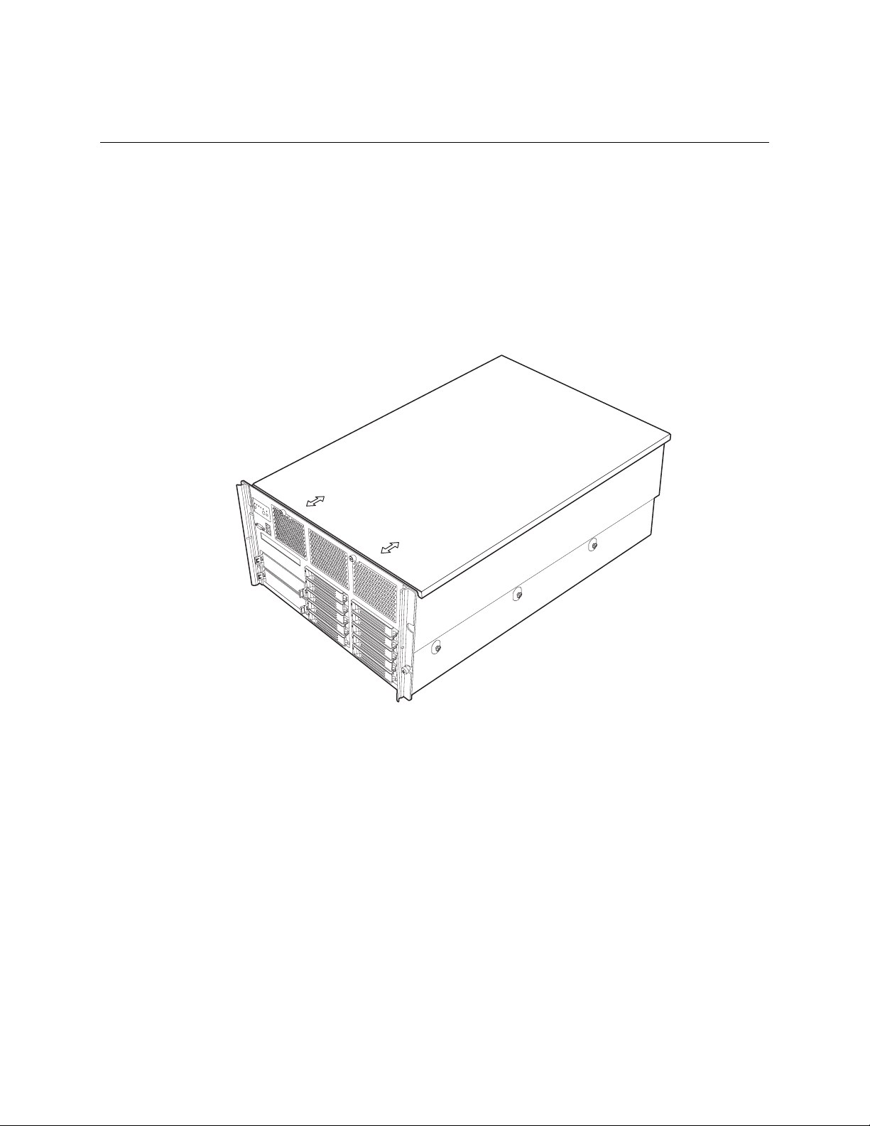
1 Platform Description
The Intel® Server Platforms SR6850HW4 and SR6850HW4/M are rack-mount or pedestal systems
with support for one to four Intel
The system is based on the Intel
are based on the Intel
®
E8500 chipset and Intel® E8501 chipset respectively. The platform supports
®
Xeon® processors and 64GB DDR2 400MHz SDRAM memory.
®
Server Board Sets SE8500HW4 and SE8501HW4, which in turn
hot-plug PCI-X* and PCI-Express* add-in cards; hot-swap, redundant power supply modules;
hot-swap, redundant cooling fans, hot-plug memory with RAS features, and hot-swap hard disk
drives.
The server platform in a rack configuration is shown below.
30
TP01503
Figure 1. Intel® Server Platforms SR6850HW4 and SR6850HW4/M Front View (Rack
Configuration)
Page 31

Figure 2 shows the front view of the chassis in the pedestal configuration with the optional snap-on
bezel in place. When the bezel is removed, the user has access to the front panel, hard drives, and
peripherals. The default configuration is the rack configuration. You must install the pedestal
conversion kit to use your server platform in the pedestal configuration.
1
2
TP01504
Figure 2. Chassis Front View (Pedestal Configuration)
31
Page 32

Platform Description
Platform Features
The platform features are outlined in the following table.
Table 1. Chas sis Feature Summary
Feature Description
Dimensions (6U rack-mount
platform)
Clearance requirements Front clearance: 3 inches (76 mm)
Configuration
flexibility/scalability
Serviceability Front access to hot-swap hard disk drives
Availability Four hot-plug PCI Express* slots
Height: 10.3 inches (262 mm)
Width: 17.6 inches (447 mm)
Depth: 27.8 inches (706 mm)
Weight of fully configured system: 105 lbs (48 kg)
Side clearance: 1 inch (25 mm)
Rear clearance: 6 inches (152 mm)
Support for one to four processors
Support for at least two generations of processors
Support for up to ten Ultra320* SCSI hard drives
Support for up to seven PCI adapters
Support for up to 64GB Double Data Rate-II (DDR2) 400 MHz
Synchronous Dynamic Random Access Memory (SDRAM)
memory DIMMs
Option for Front Panel Control Module with or without LCD
Option for 2Gb Fiber Channel Module
Option for Intel
Top access to hot-swap fans
Rear access to hot-swap power supplies
System power and system status LEDs
System ID buttons and LEDs on front panel and rear of system
Memory configuration and status LEDs
Processor failure LEDs
Color-coded parts to identify hot-swap and non-hot-swap
serviceable components
Three PCI-X* slots
Two 1570W power supplies in a redundant (1+1) configuration
Dual power cords (1+1) when two power supplies are installed
Six hot-swap system fans in a redundant (5+1) configuration
Ten hot-swap 1-inch Ultra320* SCSI hard disk drives
Four hot-plug memory boards (OS support required)
RAID on MotherBoard (ROMB) with a battery-backed DDR2
400MHz DIMM for disk cache
®
Management Module (Professional or Advanced)
32 Intel® Server Platforms SR6850HW4 and SR6850HW4/M Product Guide
Page 33

Feature Description
Manageability Server Management support via Intel® Management Module
Remote management
Emergency Management Port (EMP)
Intelligent Platform Management Interface (IPMI) 1.5 compliant,
partial IPMI 2.0 compliance
Wired For Management (WfM) 2.0 compliant
Remote diagnostics support
Front control panel System power button and
LED
System reset button
NMI button
System ID button and LED
Optional LCD
System status LED
Hard drive status LED
LAN1 and LAN2 status LEDs
Video connector
Three USB 2.0 ports
Platform Front
A
Item Description
A Video connector
B USB 2.0 ports
C Front control panel. Standard control panel shown.
D Hot-swap fan modules (six)
E 5 ¼ peripheral bays (two)
F CD-ROM / DVD-ROM drive bay
G Hot-swap drive bays (ten)
C
B
E
F
D
Figure 3. Front Accessible Components
G
TP01508
33
Page 34

Platform Description
Standard Control Panel
The standard control panel provides a user interface for system management via switches and status
LEDs. The control panel also contains the speaker. The figure below shows the location of the
buttons and status LEDs on the standard control panel.
Item Feature
A Hard Drive Status LED
(green/amber)
B, C LAN1, LAN2 Status LEDs (green)
A CB
D
G
F
E
I
H
J
Description
LED State Activity
Indicates hard drive activity and fault status.
Green On A hard drive is being
Green Blinking A hard drive is active.
Amber On Hard drive/slot failure.
Amber Slow Blinking
Amber Fast Blinking
Indicates LAN activity status.
Off Idle
On Inactive No access
Blinking Active Access
K
(~1 Hz)
(~2.5 Hz)
L
TP01505
initialized.
A predictive hard drive/slot
failure or rebuild in process.
Hard drive rebuild interrupted
or rebuild on empty slot.
34 Intel® Server Platforms SR6850HW4 and SR6850HW4/M Product Guide
Page 35

Description
D System Status/Fault LED
(green/amber)
E System Power LED (green)
F System ID LED (blue) Helps identify the system. This is useful to identify a server that is
G System Reset button Resets the system.
H System Power button Turns system power on and off.
I System ID button Turn System ID LED on and off.
K NMI button Causes a non-maskable interrupt (NMI).
Front Panel Connectors
J Video connector Video port, standard VGA compatible, 15-pin connector.
L Three USB connectors Three USB 2.0 ports, 4-pin connectors.
Figure 4. Front Panel Controls and Indicators
Indicates system status.
Off Not ready AC Power Off, POST error
Green, On Ready System booted and ready
Green,
Blinking
Amber, On Critical Alarm Critical Power Supply, Blower,
Amber,
Blinking
Indicates system power status.
Off Power off ACPI: No
On Power on ACPI: No
Off S4 / S5 ACPI: Yes
Blinking S1 ACPI: Yes
On S0 ACPI: Yes
to be serviced.
Degraded Processor or DIMM disabled
Voltage, or Temperature
failure.
Non-critical
Alarm
Redundant Power Supply or
Blower failure. Non-Critical
Blower, Voltage, and
Temperature failure.
35
Page 36
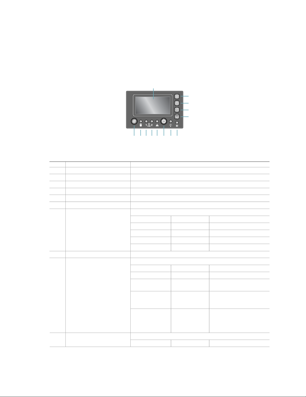
Platform Description
Intel® Local Control Panel
The Intel® Local Control Panel provides a user interface for system management through switches,
status LEDs, and the LCD panel. This control panel also contains a speaker. See the following
figure.
A
B
C
D
E
M L K J I GH F
TP01506
Item Feature Description
A LCD display Video display
B Scroll up button Press to scroll up on the LCD
C Scroll down button Press to scroll down on the LCD
D Back button Press to move to the previous LCD screen.
E Select button Press to enter a command or select an option on the LCD.
F System ID LED (blue) Helps identify the system via server management
G System Power LED (green)
H System Power button Toggles system power
I System Status/Fault LED
(green/amber)
(green)
Indicates system power status.
Off Power off ACPI: No
On Power on ACPI: No
Off S4 / S5 ACPI: Yes
Blinking S1 ACPI: Yes
On S0 Yes
Indicates system status.
Off Not ready AC power off, POST error
Green, On Ready System booted and ready
Green, Blinking Degraded Processor or DIMM
disabled
Amber, On Critical Alarm Critical power supply,
blower, voltage, or
temperature failure
Amber, Blinking Non-critical
Alarm
Indicates LAN activity status. J, K LAN1, LAN2 Status LEDs
Off Idle
Redundant power supply or
blower failure.
Non-critical blower, voltage,
or temperature failure.
36 Intel® Server Platforms SR6850HW4 and SR6850HW4/M Product Guide
Page 37
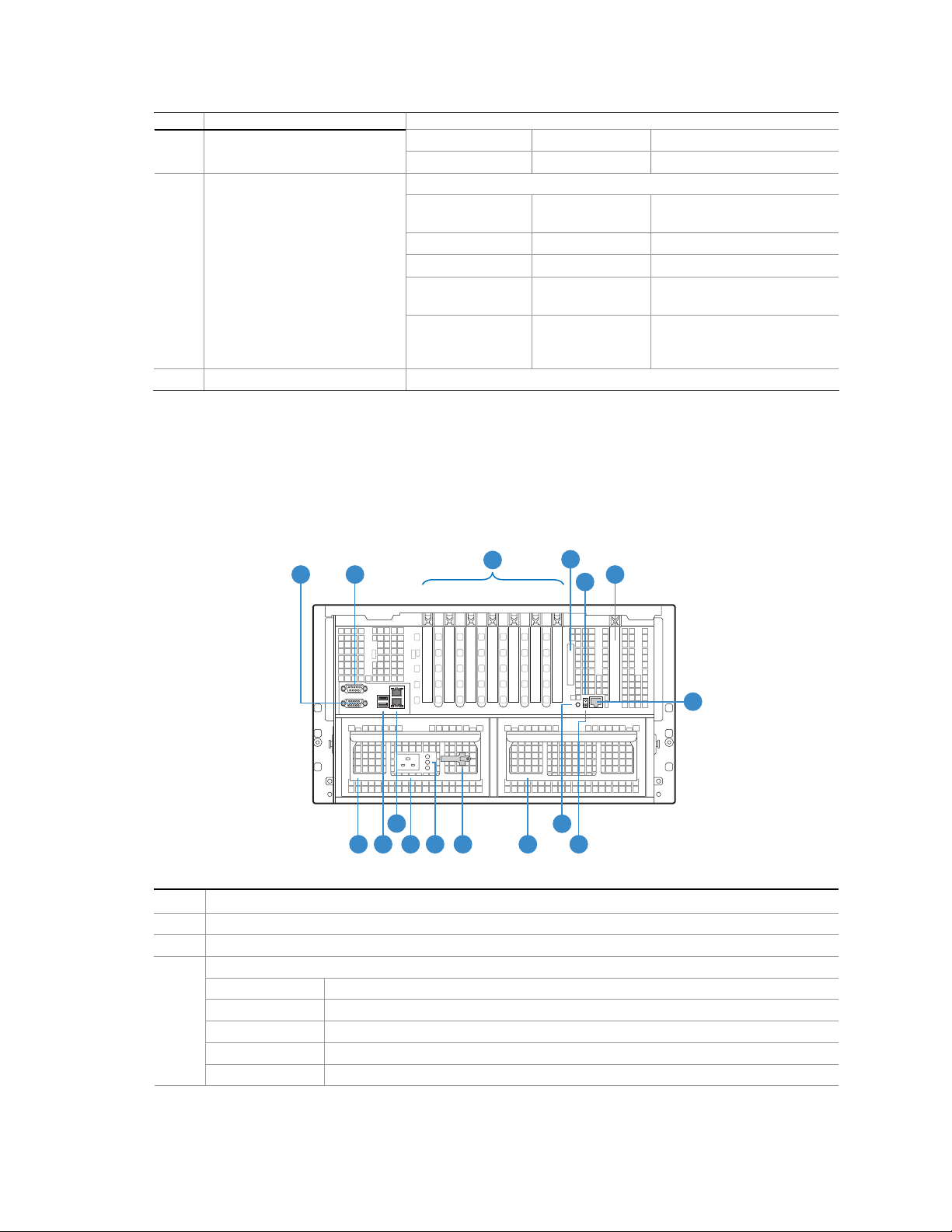
Item Feature Description
On Inactive No access
Blinking Active Access
L Hard Drive Status LED
(green/amber)
M System Reset button Resets the system
Indicates hard drive activity and fault status.
Green On A hard drive is being
Green Blinking A hard drive is active
Amber On Hard drive/slot failure
Amber Slow Blinking
(~1 Hz)
Amber Fast Blinking
(~2.5 Hz)
initialized
A predictive hard drive/slot
failure or rebuild in process
Hard drive rebuild
interrupted or rebuild on
empty slot
Figure 5. Intel® Local Control Panel
Platform Rear
The figure below shows the features found at the rear of the platform.
A
B
1743256
I
H
Item Description
A Video port, standard VGA compatible, 15-pin connector
B Serial port connector. Emergency Management Port access is provided through the serial port.
C
PCI Slots
Slot 1 PCI Express* x8 (hot-plug)
Slot 2 PCI-X* 133MHz, 64-bit (hot-plug)
Slot 3 PCI Express* x4 (hot-plug)
Slot 4 PCI Express* x4 (hot-plug)
Slot 5 PCI Express* x4 (hot-plug)
KJ
C
LG M
D
F
E
P
N
O
TP01507
37
Page 38

Platform Description
Item Description
Slot 6 PCI-X* 100MHz, 64-bit (not hot-plug)
Slot 7 PCI-X* 100MHz, 64-bit (not hot-plug)
D External SCSI connector. The external SCSI bus sup ports both LVDS and SE signals through the
external SCSI connector.
E System ID button
F Fiber Channel Module slot
G Power supply
H Two USB 2.0 ports
I
J AC input power connector
K Power supply LEDs
L Power supply release
M Active power supply blank
N System ID LED (blue)
O DC Jack
P Server Management RJ-45 connector (GCM)
Two LAN ports, RJ45 connector (LAN1 on top, LAN2 on bottom)
LAN port LEDs:
Status LED
(green)
Speed LED
(green/amber
dual color)
On – ethernet link is detected
Off – no ethernet connection
Blinking – ethernet link is active
Off – 10 Mbps
Green On – 100 Mbps
Amber On – 1000 Mbps
Figure 6. Rear Accessible Components
38 Intel® Server Platforms SR6850HW4 and SR6850HW4/M Product Guide
Page 39

Processors
The Intel® Server Platform SR6850HW4 supports from one to four 64-bit Intel® Xeon® Processor
MP with 1MB L2 Cache or 64-bit Intel
processors are targeted for multiprocessor servers. Several architectural and microarchitectural
enhancements have been added to this processor, including an increased L2 cache size and an
integrated L3 cache (64-bit Intel
®
®
Xeon® Processor MP with 8MB L3 Cache. These
Xeon® Processor MP with 8MB L3 Cache).
Plug-in Voltage Regulator Module (VRM) Converters
Two types of plug-in voltage regulator module (VRM) converters are used in the system:
L3Cache VRM9DO
VRM 10.2
Input power to the main board is 12V and 3.3VSB. All other voltages must be generated on the
board set including 3.3V and 5V. There are numerous VRDs used to generate the required voltage
levels. Processor core voltage to processors 1 and 2 is generated by embedded VRDs. Core voltage
to processors 3 and 4 comes from two 10.2 VRMs. There is one L3Cache VRM9DO required for
converting the cache voltage for processors 1 and 2. A plug-in L3Cache VRM9DO is required for
processors 3 and 4.
System Memory
The memory boards connect to the main board through x16 PCI Express* connectors. Between one
and four memory boards can be installed. Each memory board has four DIMM sockets that support
two DDR2 channels with two DIMMs per channel. The memory boards support both single-rank
and double-rank registered DIMMs. Do not use unbuffered DIMMs.
The DIMMs on each memory board must be installed in pairs. Each pair is referred to as a bank. A
bank may consist of one rank (a pair of single-sided DIMMs) or two ranks (a pair of double-sided
DIMMs). The BIOS executes a memory test prior to configuring the memory in POST when a
memory board is inserted into the system during a hot plug operation.
A DIMM bank will be disabled if any of the following occur:
Uncorrectable errors are found during a memory test
An uncorrectable ECC error occurred during runtime
The DIMM rank correctable error count passes the error sparing threshold on a memory board
where sparing is enabled
A memory board fails
If a DIMM fails the memory test, an LED will light on the memory board to identify the location of
the bad DIMM and the DIMM bank will be disabled. The failing DIMM event is logged to the
System Event Log (SEL) and the BIOS disables the memory DIMM and/or the memory board.
Upon subsequent reboots, this memory is not initialized unless the BIOS setup option “Retest all
system memory” or “Retest board memory” is selected.
39
Page 40

Platform Description
Available Memory Configurations
Four memory configurations are available in the BIOS Setup utility.
Maximum Performance: Maximum Performance is the default configuration in BIOS setup.
With this configuration, the BIOS first attempts to configure the memory boards as four-way
interleaved. If four-way interleaving cannot be accomplished, it will attempt to two-way
interleave. It will then use one-way interleaving if any remaining memory cannot be four-way
or two-way interleaved. This interleaving process configures the memory for maximum
performance. This configuration cannot be used if you want hot-add or hot-replace memory.
Maximum Compatibility: Maximum Compatibility provides the most flexibility with DIMMs
and memory boards. This option allows memory to be hot-added. Server performance will be
reduced due to one-way interleaving.
Memory Mirroring: The memory-mirroring feature provides redundancy. It uses either two or
four memory boards, paired as sets of two. Memory boards in slots A and B form one set.
Memory boards in slots C and D form the second set. One board within a set of memory boards
duplicates the second board in the set. Each memory board in a set must have the same amount
of memory installed.
When a hardware or DIMM error is detected on a primary memory board, the second board
becomes the primary board and remains primary until the failing board or DIMM is replaced.
Memory Mirroring uses board-level redundancy, allowing for hot-replace. Hot-add is supported
by adding two additional mirrored memory boards.
The BIOS turns on the mirror LED on each memory board when the system is configured for
mirroring.
Memory RAID: If the server contains four memory boards with equal memory capacity, the
system can be configured for memory RAID. Data is written to three of the memory boards
while one is reserved for redundant parity information. This reduces the total overall available
memory by one-fourth. The RAID LED on the memory board will indicate that the memory
board is in a RAID configuration.
When a DIMM rank or board fails, the system will continue to operate with the remaining three
boards by recreating the data from the failed board. The system loses its redundancy at this
point, and will remain in this non-redundant state until the failing board and/or memory can
then be replaced.
This configuration allows for hot-replacement of failing memory boards and hot-add and hotreplacement of memory DIMMs.
40 Intel® Server Platforms SR6850HW4 and SR6850HW4/M Product Guide
Page 41

The server BIOS also includes two additional memory reliability, accessibility, and serviceability
(RAS) features:
Memory Sparing: A rank on each memory board can be reserved as a “spare” and can only be
used as a backup for other ranks on the same memory board. The memory rank that is
configured as spare is held in reserve and cannot be used by the operating system. Hot removal
cannot be performed when in a Memory Sparing configuration.
When the error rate for a failing rank exceeds an established threshold, the contents of that rank
are copied to the spare rank. At the completion of the copy, the failing rank is disabled and the
spare is used in its place. This is called Memory Sparing. By enabling memory sparing, the total
memory of each memory board is reduced by the largest DIMM rank installed on the memory
board. This ensures that the any failing rank will fit on the spare rank.
When the failing rank switches to the spare, the BIOS will turn on the memory board LED to
indicate the bad DIMM. The failing DIMM is then disabled on subsequent system boots.
Memory Hot Plug: This memory RAS feature provides the ability to hot-replace and hot-add
memory boards while the system is running. This feature can be used to perform:
- Memory Hot Replace: While the system is in operation, you can remove a failed memory
board, provided it is in a RAID or Mirror configuration, and replace it with a board of the
same memory capacity. The system will test, initialize, and rebuild the data on the memory
board and then include this board in the system memory configuration. The activity is
transparent to the operating system,
- Memory Hot Add: You can increase the memory capacity of the system while the operating
system is active. In a RAID or Mirror configuration, you can remove one memory board at a
time to upgrade the memory or replace the memory board. In a Mirror configuration, you can
add an addition two mirrored memory boards. In a Maximum Compatibility configuration, a
new memory board can be added to an empty slot. When the initialization is complete, the
OS is informed of the new memory.
NOTE
Memory Hot Add must be supported by the operating system in order to
perform this function. Check for an operating restrictions.
41
Page 42

Platform Description
Power Subsystem
The power subsystem consists of the following:
Power supply modules
Plug-in VRM converters
The power distribution board
The power subsystem can be configured as following:
Two power supply modules installed, (1+1) redundancy at 220 VAC, 115/120/127 VAC, and
100/110 VAC
One power supply module installed, non-redundant at 100/110 VAC, 115/120/127 VAC, 220
VAC
NOTE
For low-line power environments (100 through 127VAC), verify the
configuration of the main board jumper CP_Type (J4G3). See “
Information”.
Jumper
Power Supply Modules
The output rating of the power supply is 1570W when operated between 170VAC and 264VAC. It
is a current-sharing power supply with auto-ranging input. The power supply is about 7.7-inches
wide x 14.5-inches deep x 3.5-inches high. The power supply modules have universal AC input
with Power Factor Correction (PFC) Distributed Power Supplies (DPS).
The AC input receptacle is an IEC-320 C20 20A rated for 250VAC. The power supply has two DC
outputs: 12 V (main) and 3.3 V (standby). The 12 V main power is distributed throughout the
server and is converted locally at the point-of-load using either embedded or plug-in VRM
converters. The power supply is capable of power-safe monitoring.
In an N+ 1 configuration, the 12 VDC outputs have active (forced) current sharing. The two
externally enabled outputs have the following ratings:
+12 VDC at: 163A at HI line / 141A at LO line
+3.3 VDCSB at: 6.2A at any line
Each power supply module requires one power cord to supply AC power to the system. When two
power supply modules and two power cords are installed, the system supports (1+1) power cord
redundancy. This feature allows the system to be powered by two separate AC sources. In the 1+1
configuration, the system continues to operate without interruption if one of the AC sources fails.
42 Intel® Server Platforms SR6850HW4 and SR6850HW4/M Product Guide
Page 43

Each power supply module has three status LEDs located next to the input connector, as shown in
Figure 7.
A
B
C
TP01509
Location Purpose Description
A (Top) Power Good LED
(green)
B
(Center)
C
(Bottom)
Fault LED (amber) This amber LED is driven by internal circuitry and is lit when a power
AC OK LED (green) This green LED is driven by internal circuitry and is lit whenever the
This green LED is driven by internal circuitry and is lit whenever the
power is turned on.
rail has failed. The LED is lit even if the power supply is in a latched
state. The only time (during a fault) when it is not lit is if the +3.3VSB
is lost.
The LED is not lit when the power supply is turned off by powering
down the platform.
AC power cord is plugged in to an active AC power source.
Figure 7. Power Supply Indicators
NOTE
Proper system cooling requires that either two power supplies, or a single
power supply and a power supply filler panel that contains a cooling fan be
installed at all times.
43
Page 44

Platform Description
Cooling Subsystem
CAUTION
The chassis top cover must be installed for proper system cooling. Cooling
components must be hot-swapped within a limited time. This time applies
only to the time that the cooling component is physically removed, not from
the time of failure.
The cooling subsystem consists of hot-swap, redundant (5+1) fans and the fans in the power supply
modules. In the event of a cooling component failure, system cooling is maintained and the system
continues to operate while the component is being hot-swapped. Each fan has a single LED to
indicate its status. The LED will illuminate green while the fan is operating normally. The LED will
illuminate amber if the fan has failed. Failed fans can be hot-swapped from the top of the chassis
once the top cover is removed.
TP01492
Figure 8. System Fan LED Indicator
The processor heatsink baffle must always be in place. Systems that are not fully configured with
four processors and four memory boards must keep the processor heatsink and memory board
fillers installed to maintain proper cooling.
44 Intel® Server Platforms SR6850HW4 and SR6850HW4/M Product Guide
Page 45

Hot-swap PCI Slots
The five hot-plug PCI slots each have power and attention LEDs. The Attention button is used to
invoke a hot-plug sequence to remove or add an adapter without having to use the software
interface. They are located by the green arrow on the PCI divider label. The status of the LEDs is
shown in
Table 2. Power Indicator
Power LED (green) Definition
Off
On Power ON: Slot is powered on. Card cannot be inserted or removed.
Blinking
Table 3. Atten tion Indicator
Attention LED (amber) Definition
Off Normal: Normal Operation
On Attention: Power fault or Operational problem at this slot
Blinking Locate: Slot is being identified at the user’s request.
Table 2 and Table 3.
Power OFF: All main rails have been removed from slot. Card can be
inserted or removed.
Power Transition: Slot is in the process of powering up or down. Card
cannot be inserted or removed.
NOTE
If you hot-remove a PCI card without following the proper procedure, power
will automatically be turned off to the slot.
45
Page 46

Platform Description
Peripherals
The Intel® Server Platform SR6850HW4 supports the following peripheral devices:
Ten hot-swap hard drives bay (1-inch Ultra320* SCSI)
One ½-inch IDE DVD/CD-ROM
Two full-height tape back-up devices.
A
Item Description
A Video connector.
B USB ports (three).
C Front panel control module. Standard module shown.
D Fan modules (six).
E 5 ¼ inch peripheral device (two)
F DVD-ROM / CD-ROM drive
G Hard drives (ten).
C
B
E
F
D
Figure 9. Peripheral Area
G
TP01508
46 Intel® Server Platforms SR6850HW4 and SR6850HW4/M Product Guide
Page 47

Hard Disk Drive Support
NOTE
Because hard disk drives have different cooling, power and vibration
®
characteristics, Intel validates specific hard disk drive types in the Intel
Server Platform SR6850HW4. See the Intel
®
Server Platform SR6850HW4
Tested Hardware and Operating System List for a list of the supported
drives.
Hot-Swap Hard Disk Drive Bay
The hot-swap hard disk drive carrier is designed to accommodate 15,000-RPM (and slower)
Ultra320* SCSI technology SCA-type hard disk drives.
The SCSI backplane supports Low Voltage Differential (LVD) SCSI disk drives only. SingleEnded (SE) SCSI devices are not supported internally. SE drives are only supported on the external
SCSI connector.
A
B
TP01510
Item Description
A Latch
B Dual-color activity LED:
Green flashing: Indicates hard drive is active.
Amber and green alternating flashing: Indicates hard drive is powered on
and is rebuilding RAID, or it is powered on and has a fault condition.
Amber flashing: Indicates hard drive is not powered on and has a fault
condition.
Unlit: Indicates no hard drive is installed in that location or a drive is
installed, but no drive activity is taking place.
Figure 10. Hard Disk Drive Carrier
47
Page 48

Platform Description
Removable Media Bay Support
The DVD/CD-ROM drive is installed in a sheetmetal carrier and is inserted from the front of the
chassis. The tape back-up drive is also installed from the front of the chassis. The user must switch
off system power and remove the top cover to remove or install these devices.
TP01511
Figure 11. CD-ROM/DVD-ROM Drive Carrier
Platform Board Set
This section highlights the main features of the board set. The board set contains the following:
One main board
Up to four memory boards
In addition, the server contains the following system boards:
Front panel board
SCSI backplane board
Power distribution board
SATA-to-IDE Adapter board
The following figure shows a block diagram of the system and the board set within the system.
48 Intel® Server Platforms SR6850HW4 and SR6850HW4/M Product Guide
Page 49
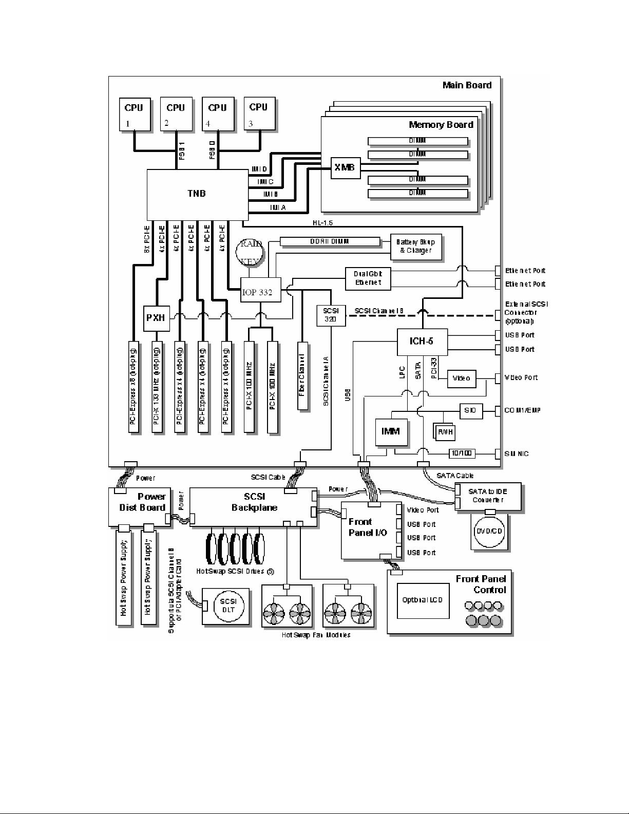
Figure 12. Server Platform Block Diagram
49
Page 50

Platform Description
Main Board
The main board consists of the Intel® E8500 chipset, four memory board connectors, and slots for
®
PCI Express* and PCI-X* adapters. The board also has support for the Intel
Management Module,
a custom Fibre Channel module connector, on-board video, Gigabit ethernet, USB2.0, Serial-ATA,
Ultra320* SCSI, dual flash memory components for BIOS, and RAID On Motherboard (ROMB)
support.
A B D E F G I J K LHC
HH
GG
M
FF
EE
DD
CC
BB
AA
N
O
P
Q
R
S
Z
CPU 1CPU 2CPU 4CPU 3
T
UVWY X
TP01530
Item Description Item Description
A Generic Communication Module (GCM) R Memory board Slot B
B Intel® RAID Activation Key S DC power connectors
C PCI-X* 100MHz (Slot 7) T Power distribution board (PDB) signal
connector
D PCI-X* 100MHz (Slot 6) U Processor socket 1
E PCI Express* x4 – Hot Plug (Slot 5) V Processor socket 2
F PCI Express* x4 – Hot Plug (Slot 4) W Processor socket 4
G PCI Express* x4 – Hot Plug (Slot 3) X VRM 10.2L connector (CPU 4)
H PCI-X* 133MHz – Hot Plug (Slot 2) Y Processor socket 3
I PCI Express* x8 – Hot Plug (Slot 1) Z SCSI Connector channel A (internal)
J Ethernet LAN 1 (top), LAN 2 (bottom) AA VRM 9.1 Connector (processor cache)
K Dual USB port s BB VRM 10.2LD Connector (processor 4)
50 Intel® Server Platforms SR6850HW4 and SR6850HW4/M Product Guide
Page 51

Item Description Item Description
L Serial / EMP (top), video connector
(bottom)
M Memory board Slot A DD SCSI Connector Channel B (external)
N Real-time clock battery EE On board RAID Cache memory (DDR-2)
O SATA connector FF Memory board Slot D
P Front panel co nnector GG Fibre Channel Module connector
Q Intel® Management Module HH Memory board Slot C
CC On board Intel® RAID Battery Backup
Unit connector
connector
Figure 13. Main Board Component Locations
The main board supports the following:
®
Up to four 64-bit Intel
Xeon® processor MP with 1MB L2 Cache or 64-bit Intel® Xeon®
processor MP with 8MB L3 Cache
Intel
®
E8500 chipset
- Intel
®
E8500 Northbridge: has two shared 64-bit FSB interfaces configured for symmetric
multiprocessing.
- External memory board (XMB): provides support for 400MHz DDR2 memory.
- PXH: provides support for PCI-X*
®
- Intel
- Intel
IOP332 I/O Processor with Intel XScale® Microarchitecture provides support for
PCI-X* and contains Intel XScale
®
82801EB I/O Controller Hub 5 (Southbridge) provides support for system BIOS,
®
technology to support ROMB.
USB2.0, and SATA.
Advanced I/O Architecture
- One hot-plug x8 PCI Express* slot
- Three hot-plug x4 PCI Express* slots
- One hot-plug 133MHz, 64-bit PCI-X* slot
- Two 100MHz, 64-bit PCI-X* slots (Non hot-plug)
LSI Logic* 53C1030 LVD SCSI Controller
- Dual independent U320 SCSI interfaces
- 64-bit PCI-X* 100Mhz interface
Integrated ATI Technologies Inc* Radeon 7000M with 16MB embedded SDRAM
®
Intel
Fiber Channel Module with a 64-bit PCI-X* 100Mhz interface
USB 2.0 Support
- Two ports in the rear of chassis
- Three ports on the front panel
51
Page 52

Platform Description
SCSI Controller
A single LSI* 53C1030 Ultra320* LVDS controller provides the integrated SCSI interfaces. The
controller resides on PCI Bus Segment A (PX1A) off the Intel
®
XScale
Microarchitecture. It communicates as a 64-bit PCI-X* device for optimum performance.
®
IOP332 I/O Processor with Intel
The controller’s PCI-X* interface operates at a bus speed of 100 MHz. The configuration registers
define PCI-related parameters for the LSI* 53C1030 device. The LSI* 53C1030 supports all
mandatory registers in the PCI configuration space header including the following:
Vendor ID
Device ID
Class Code
Revision ID
Header Type
Command fields
Status fields.
The LSI* 53C1030 supports two Ultra320* LVDS channels. One is for control of internal drives,
and the other is for a high-speed connection to an external SCSI device. SCSI port A from the LSI*
53C1030 controls the internal SCSI channel. The internal channel is routed to the Intel
Platform SR4850HW4 SCSI backplane board via a SCSI U320 cable. The internal channel has
been validated only for LVDS operation. SCSI port B may be used for the tape drive, external SCSI
port, or an add-in adapter.
SATA Drive Support
®
Server
Intel® Server Board SE8500HW4 Main Board has a 7-pin vertical connector supporting one SATA
(Serial ATA) port, which is integrated in the ICH-5 component. The port can support a serial data
transfer rate up to 1.5 Gb/second.
RAID Support
The Intel® Server Board SE8500HW4 supports on-board RAID through the Intel® IOP332 I/O
Processor with Intel XScale
controller. The server platform supports RAID 0, 1, 5, 10, and 50 configurations. A 2MB flash
component and a non-volatile SRAM store the LSI* code and hardware configuration information.
To activate this feature Intel
board and a DDR-2 DIMM must be installed into the RAID DIMM socket. This DIMM serves as
memory for the Intel
®
cache to store write data to the drives.
There is also an option to install the Intel
®
to the Intel
IOP332 I/O Processor with Intel® XScale® Microarchitecture drops below
specifications, the Intel
DIMM in self-refresh mode until power is restored. After power is restored, the data is safely
written to drives, maintaining the integrity of the disk array.
®
Microarchitecture in conjunction with the LSI* 53C1030 SCSI
®
RAID Activation Key must be installed into the holder on the main
IOP332 I/O Processor with Intel® XScale® Microarchitecture, and as a disk
®
RAID Smart Battery. With the Smart Battery, if power
®
RAID Smart Battery maintains the contents of the DIMM. It keeps the
52 Intel® Server Platforms SR6850HW4 and SR6850HW4/M Product Guide
Page 53

Video Support
The Intel® Server Board SE8500HW4 Main Board features the ATI Radeon 7000 Embedded Video
Controller with 16MB of video RAM. The Radeon 7000 provides the following features:
2D/3D/video accelerator
Dual DAC for integrated, cost-effective multi-panel support
DVI compliant integrated 165MHz TMDS transmitter
Resolutions from VGA up to UXGA (1600x1200)
32-bit PCI host interface
The Intel
®
Server Board SE8500HW4 Main Board has a standard DB15 video connector.
Fibre Channel Module Support
The Intel® Fibre Channel Module has a dedicated slot on the main board. The module is based on
the Qlogic* ISP2322 FC-PCI-X* controller.
The following features are available on the Fibre Channel Module:
Two independent 2 Gbps serial Fibre Channel ports
Support for Fibre Channel virtual interface (VI) protocol
Support for 2 Gbps Fibre Channel using internal or external transceivers
Automatically negotiates Fibre Channel bit rate (1 Gbps or 2 Gbps)
Supports up to 400 MBps sustained Fibre Channel data transfer rate
Data and code parity protection
Complete SCSI, IP, or VI operations without host intervention
Optical FC interface
Ethernet Support
The Intel® Server Board SE8500HW4 has 1000/100/10 Ethernet capability as supported by the
embedded Broadcom* BCM5704C Gigabit Ethernet Controller. The BCM5704C is a fully
integrated dual-port, 10/100/1000BASE-T Gigabit Ethernet media access control, and physical
layer transceiver solution for high-performance network applications.
The BCM5704C is an integrated solution combining two triple-speed, IEEE 802.3-compliant media
access control (MAC), PCI, and PCI-X* bus interfaces, an on-chip buffer memory, and an
integrated physical layer transceiver in a single device. The BCM5704C includes two 10/100/1000Mbps Ethernet MACs with full/half-duplex capability at all speeds and two 10/100/1000 copper
PHYs. Support for the following 802.3 functions is featured in the MAC: VLAN tagging, layer 2
priority encoding, link aggregation, and full-duplex flow control.
53
Page 54
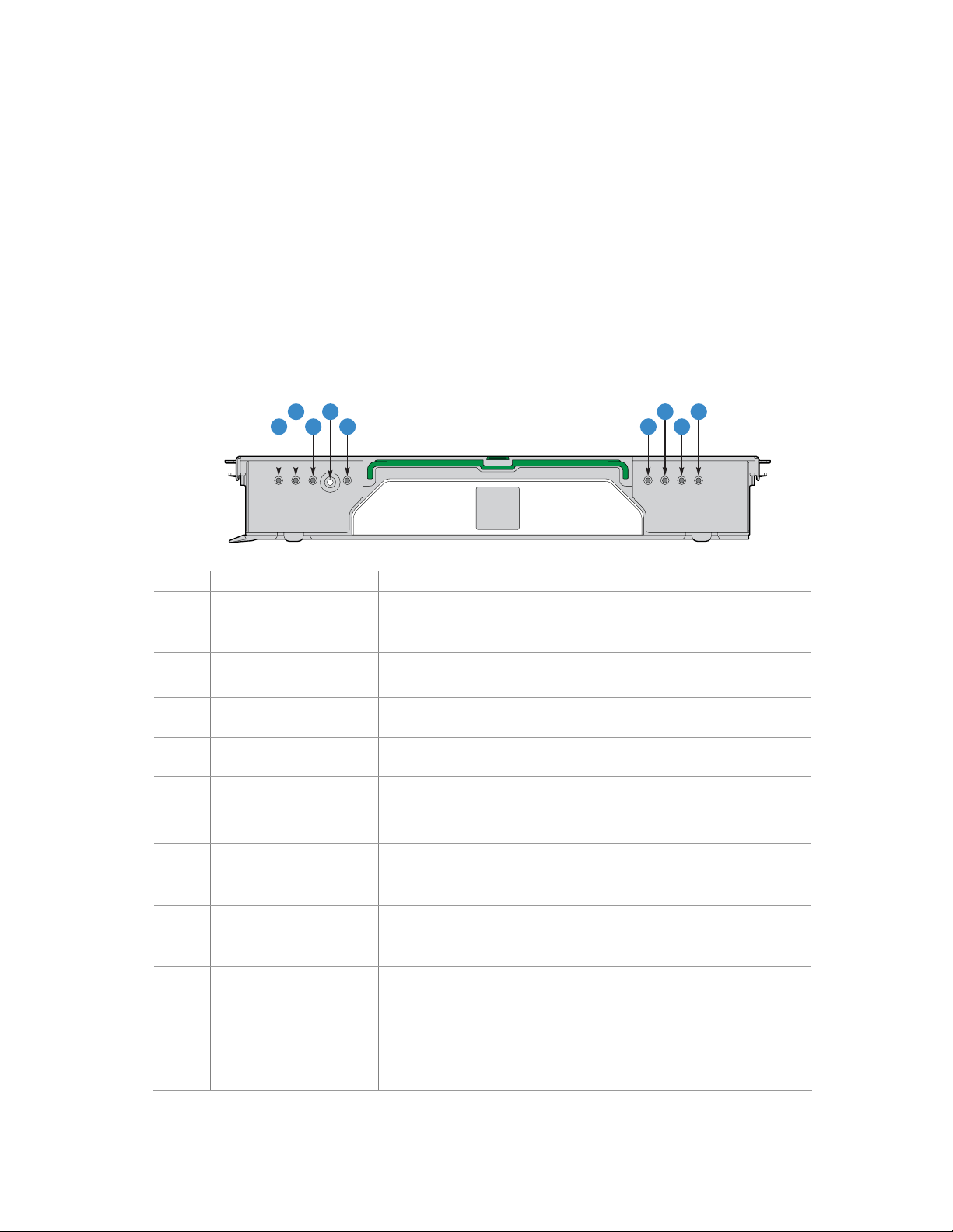
Platform Description
Memory Board
Up to four memory boards can be installed. Each memory board has four DIMM sockets that
support two DDR2 channels with two DIMMs per channel. The memory boards support both
single-rank and double-rank registered DIMMs. Unbuffered DIMMs are not supported. The
memory boards connect to the main board through x16 PCI-Express connectors.
The Independent Memory Interface (IMI) bus connects the eXtended Memory Bridge (XMB) on
®
the memory board and the Intel
on the main board. The I
2
C bus also goes through the memory connector linking the FRU device on
E8500 chipset North Bridge or Intel® E8501 chipset North Bridge
the memory board to the server management (SM) bus on the main board.
The hot-plug memory boards have LEDs indicating the configuration and status of the DIMMs on
the hot-plug memory board. See the following diagram.
A
C E
Item Feature Description
A
B
C
D Attention Button
E Power LED (green) LED on: Power is detected. The memory board is powered on.
F
G
H
I
Mirror Configuration
(green)
RAID Configuration
(green)
Hot plug Attention LED
(amber)
DIMM 1B Status LED
(amber)
DIMM 1A Status LED
(amber)
DIMM 2B Status LED
(amber)
DIMM 2A Status LED
(amber)
LED on: The server is in Memory Mirror configuration. This
memory board mirrors another memory board in the system.
LED off: The server is not configured for memory Mirror
LED on: The server is in RAID memory configuration.
LED off: Server is not in a RAID configuration.
.
Press this button to perform a hot-insertion or hot-removal of a
memory board.
LED off: Power is not detected on all boards.
LED flashing: The memory board is in a hot-plug event
LED on: Error LED for DIMM slot 1B (J3A1). The DIMM is
malfunctioning and needs to be replaced.
LED off: The DIMM is functioning properly.
LED on: Error LED for DIMM slot 1A (J3A2). The DIMM is
malfunctioning and needs to be replaced.
LED off: The DIMM is functioning properly.
LED on: Error LED for DIMM slot 2B (J3B1). The DIMM is
malfunctioning and needs to be replaced.
LED off: The DIMM is functioning properly.
LED on: Error LED for DIMM slot 2A (J3B2). The DIMM is
malfunctioning and needs to be replaced.
LED off: The DIMM is functioning properly.
F
D
B
I
G
H
TP01512
54 Intel® Server Platforms SR6850HW4 and SR6850HW4/M Product Guide
Page 55

Figure 14. Hot-Plug Memory Board LEDs
Front Panel I/O Board
The Intel® Server Platform SR6850HW4 Front Panel I/O board provides access to the video and
USB interfaces.
A
TP01488
A Front panel bo ard connector
Figure 15. Front Panel Board Component Location
®
The Intel
Server Platform SR6850HW4 and SR6850HW4/M Front Panel board provides the
following functions:
USB Port
- External front panel connector for three USB 2.0 ports
- Filtering for the USB signals
- Bulk Capacitance and fused power for USB ports
Video Output
- External front panel 15-pin VGA connector
- Required safety fusing and EMI filtering
Speaker
- Audible beep-code and alarm speaker
Front Panel Control Board
The front panel control board contains the following front panel buttons and LEDs and connects to
the SCSI-backplane board:
Buttons
- NMI button
- System ID button
- System reset button
- System power button
System status LEDs
- Hard disk drive status
55
Page 56

Platform Description
- LAN1 and LAN2 status
- System status / fault
- System power
- System ID
SCSI Backplane Board
The SCSI backplane board contains ten 80-pin Single Connector Attachment (SCA)-2 connectors
to support up to ten hard hot-swap SCSI hard disk drives. The SCSI backplane board performs the
tasks associated with hot-swapping the hard disk drives and enclosure monitoring and management.
SCSI channel ‘B’ can be re-cabled as a dedicated SCSI channel for a high-speed connection to an
external SCSI device.
A CB
I
H
Item Description Item Description
A Front panel co ntrol board connector F SCSI Channel B connector
B Main board connector G Hot-swap hard drive connectors (ten)
C Fans 3 – 6 connector H Power distribution board connector
D SCSI Channel A connector I Front panel I/O board connector
E Fans 1 – 2 connector
Figure 16. SCSI Backplane Board Component Locations
D
E
G
F
TP01489
The SCSI backplane board provides several functions for the system.
Ultra320* LVD SCSI bus passes SCSI signals between the SCSI drives and the main board
Two standard 68-pin SCSI connectors provide two independent SCSI bus connections to the
main board
Ten 80-pin SCA-2 blind-mate connectors to mate with SCSI drives on the two buses
Enclosure management
SCSI Accessed Fault-Tolerant Enclosures (SAFTE) Interface Specification
SCSI Power Control
56 Intel® Server Platforms SR6850HW4 and SR6850HW4/M Product Guide
Page 57

LED control logic
Server man a gement I
Fan presence sensing and fan fault LED control
2
C Serial EEPROM (FRU)
I
Temperature sensors
SAFTE controller firmware update capability
Interconnect for optional LCD front panel control board
Voltage regulators
12VDC to 5VDC
5VDC to 3.3VDC
5VDC to 1.8VDC
System fan control for six fans
USB 2.0 Hub
Front panel control board video interconnect and termination
Driver circuit for speaker on the front panel I/O board
Push-button signal buffering
Power connectors for DVD and tape drive cables
In-System Programming (ISP) connector for PLD programming
2
C interface
Power Distribution Board
The power distribution board provides docking connectors for the hot-swappable power supply
modules and distributes power to the main board and SCSI backplane. The board also contains
EEPROM FRU information storage.
Server Management
The Baseboard Management Controller (BMC) monitors system platform management events and
logs their occurrences in the non-volatile System Event Log (SEL). This includes events such as
over-temperature and over-voltage conditions, and fan failures. The BMC can also provide the
interface to the monitored information so system management software can poll and retrieve the
present status of the platform.
The BMC also provides the interface to the non-volatile Sensor Data Record (SDR) Repository.
Sensor Data Records provide a set of information that system management software can use to
automatically configure itself for the number and type of IPMI sensors (such as temperature and
voltage sensors) in the system.
57
Page 58

Platform Description
The following is a list of the major functions of the BMC:
System power control (including providing Sleep/Wake push-button interfaces for ACPI
Platform Event Paging (PEP) / Platform Event Filtering (PEF)
Monitoring:
- Power distribution board monitoring
- Temperature and voltage monitoring
- Fan failure monitoring
- Processor presence monitoring (no processors installed) and processor temperature
monitoring
- Interlock monitoring
Processor core ratio speed setting
Speaker beep capability on standby and when system is powered up
Hot-plug PCI slot status reporting
Chassis control:
- General fault light control
- Chassis cooling failure light control
- Chassis power fault light control
- Chassis power light control
- Chassis ID LEDs control
System Event Log (SEL) interface
Sensor Data Record (SDR) repository interface
SDR/SEL timestamp clock
Board set FRU information interface
Fault resilient booting
System management watchdog timer
Front panel system diagnostic-interrupt handling
Platform Management Interruption (PMI) / System Diagnostic Interrupt (SDI) status monitor
Event receiver
System interface to the IPMB (via system interface ports)
IPMI Management Controller Initialization Agent (MCIA)
Emergency Management Port (EMP) interface
Serial/modem and LAN alerting
In this platform, the BMC is also the chassis bridge controller, providing integrated ICMB support.
ICMB transports server management information between chassis in a cluster configuration that
can contain multiple servers and peripherals.
58 Intel® Server Platforms SR6850HW4 and SR6850HW4/M Product Guide
Page 59

2 Starting Up and Shutting Down the Server
Plugging the Server into AC Power
When the server is plugged into the AC power, the server will power cycle after a 30-second delay.
This is required to initialize the Out Of Band functionality of the BMC. Once the server completed
the power cycle, the server can be powered on using the power button on the front control panel.
NOTE
When installing a new Intel® Management Module ensure to update the BMC with the correct
server firmware. The firmware is updated after the server is powered on. Using incorrect BMC
firmware may affect operation of the front control panel’s power button.
Powering On the Server
To power on the server, press the power button on the front control panel. Pressing this button
causes the server fans to start and POST to begin running.
NOTE
It may take three minutes or longer for video to be displayed, depending on
the amount of memory installed in the system.
At the BIOS splash screen, the System Options Menu may be accessed by pressing a key on the
keyboard. In the System Options Menu, the BIOS version, copyright information and the following
options are displayed:
Continue Booting (Selected by default, and will occur automatically after a pre-set timeout
expires)
Boot Manager: Select this to boot from one of the available boot options
Boot Maintenance Manager: A menu of items that allows you configure boot options and other
boot environment variables
BIOS Setup Utility: Select this to configure the systems BIOS settings
POST Error Manager: Select this to view POST errors detected by the system
From the boot manager, the system will boot from the available boot devices. It will attempt to boot
from the first device on the list of available devices. If this device is not available, it will move to
the second device. It will continue to move down the list until it reaches the first available device.
59
Page 60

Starting Up and Shutting Down the Server
Shutting Down the Server
1. Exit the operating system (if applicable)
2. Press and hold the power button until the server shuts down.
CAUTION
Powering down the server with the power button does not remove all power
from the system. The +3.3V standby power is still available to the system
even when it is not running. To remove standby power from the system,
unplug all power cords from the system.
60 Intel® Server Platforms SR6850HW4 and SR6850HW4/M Product Guide
Page 61

3 Intel® Server Deployment Toolkit
The Intel® Server Platforms SR4850HW4 and SR6850HW4 Deployment Toolkit is a CD that
provides the following software contents:
Utilities:
- SEL Viewer Utility
- FRU Viewer Utility
- System Configuration Wizard (SCW)
- System Configuration Utility (Syscfg)
The Intel
Adobe* Acrobat Reader
The Intel
an HTML user interface that can be used to:
Access the drivers for the on-board components for the various operating systems.
Run the Platform Confidence Tests.
Put the utilities onto a CD-ROM disk or USB flash memory device.
Run the Server Configuration Wizard to setup the server for out-of-band functionality.
®
Server Platform SR6850HW4 and SR6850HW4/M User Guide (this document)
®
Server Platforms SR4850HW4/M and SR6850HW4/M Deployment Toolkit comes with
NOTES
For information on creating a DOS bootable USB flash memory device,
see “Creating a DOS bootable USB flash device”.
To create a DOS-bootable CD ROM see the instructions that came with
your CD ROM burning software.
Running Software Utilities from the CD
The following procedure allows you to run the software utilities directly from the Intel® Server
Platforms SR4850HW4 and SR6850HW4 Deployment Toolkit CD.
1. Insert the Intel
into the server’s CD-ROM drive.
2. Turn on the system. Allow the system to boot to the CD.
3. Exit the SCW utility.
4. At the DOS prompt, type dir
5. Select the directory for the utility you would like to run. Type cd directoryname
<Enter>, to change directories.
6. Type filename.exe <Enter>, to run the utility, where filename.exe is the executable
program for the utility.
®
Server Platforms SR4850HW4/M and SR6850HW4/M Deployment Toolkit CD
61
Page 62

4 Server Platform Utilities
BIOS Setup Utility
The BIOS Setup Utility is a text-based utility that allows you to configure the system and view and
change device settings and view environmental information for the platform. The BIOS Setup
Utility interface consists of several screens, called pages. Each page contains information or links to
other pages. The first page in Setup displays links for general categories. These links lead to pages
containing specific configuration settings.
The BIOS Setup Utility includes the following features:
Localization: The BIOS Setup Utility uses the Unicode standard and is capable of displaying
the Setup Utility in all languages that are currently included in the Unicode standard.
Console Redirection: The BIOS Setup Utility is functional through console redirection over
various terminal emulation standards. This may limit some functionality due to compatibility.
For example, colors, some keys or key sequences use and support for pointing devices may be
limited.
The BIOS Setup Utility is accessed from the System Options Menu. To access the Systems Options
Menu, boot the server. During POST, you will see a note telling you the key to press to accesses the
System Options Menu. Press the key when you see the message.
BIOS Setup Utility Page Layout
The BIOS Setup Utility page layout is sectioned into functional areas. The following table lists and
describes the functional areas and their positioning on the screen.
Table 4. BIOS Setup Utility Page Layout
Functional Area Description
Menu Selection Bar
Current Menu
Setup Item List
Item Specific Help Area
Keyboard Command Area
Status Bar
The Menu Selection Bar is located at the top of the screen. It displays the
major menu selections available.
The current menu is located below the Menu Selection Bar. It displays the
title of the menu the user is currently viewing.
The Setup Item List is a set of configurable and informational items. The
left column shows the setup item. The right column shows the
corresponding option. The option contains an informational value or
possible settings for the setup item.
The Item Specific Help area is located on the right side of the screen and
contains help text for the highlighted Setup Item. Help information
includes the meaning and usage of the item, allowable values, and the
affects of the options.
The Keyboard Command Bar is located at the bottom of the screen and
displays help for keyboard special keys and navigation keys. The
keyboard command bar is context-sensitive. It displays keys relevant to
the current page and mode.
The Status Bar is on the bottom line of the screen. The status value “NV”
indicates you have made changes to Setup that have not been saved.
62
Page 63

Keyboard Commands
The bottom right portion of the Setup screen provides a list of commands that are used to navigate
through the BIOS Setup Utility. These commands are context sensitive.
The Keyboard Command Bar supports the following key presses:
Table 5. BIOS Setup : Keyboard Commands
Key Option Description
<Enter> Execute
Command
<Esc> Exit The <Esc> key provides a mechanism for backing out of any field. This
Up
Arrow
Down
arrow
Left and
Right
Arrow
<Tab> Select Field The <Tab> key is used to move between fields. For example, <Tab> can
<-> Change Value The minus key on the keyp ad is used to change the value of the current
<+> Change Value The plus key on the keypad is used to change the value of the current
Select Item The up arrow is used to select the previous value in a p ick list, or the
Select Item The down arrow is used to select the next value in a menu item’s option
Select Menu The left and right arrow keys are used to move between the major menu
The <Enter> key is used to activate sub-menus when the selected
feature is a sub-menu, or to display a pick list if a selected option has a
value field, or to select a sub-field for multi-valued features like time and
date. If a pick list is displayed, the <Enter> key will select the currently
highlighted item, undo the pick list, and return the focus to the parent
menu.
key will undo the pressing of the <Enter> key. When the <Esc> key is
pressed while editing any field or selecting features of a menu, the
parent menu is re-entered.
When the <Esc> key is pressed in any sub-menu, the parent menu is reentered. When the <Esc> key is pressed in any major menu, the exit
confirmation window is displayed and you are asked whether chang es
can be discarded. If “No” is selected and the <Enter> key is pressed, or
if the <Esc> key is pressed, you are returned to where you were before
<Esc> was pressed without affecting any existing settings. If “Yes” is
selected and the <Enter> key is pressed, setup is exited and the BIOS
continues with POST.
previous option in a menu item's option list. The selected item must then
be activated by pressing the <Enter> key.
list, or a value field’s pick list. The selected item must then be activated
by pressing the <Enter> key.
pages. The keys have no affect if a sub-menu or pick list is displayed.
be used to move from hours to minutes in the time item in the main
menu.
item to the previous value. This key scrolls through the values in the
associated pick list without displaying the full list. This key only works for
date and time.
menu item to the next value. This key scrolls through the values in the
associated pick list without displaying the full list. On 106-key Japanese
keyboards, the plus key has a different scan code than the plus key on
the other keyboard, but will have the same effect. This key only works for
date and time.
63
Page 64

Server Platform Utilities
Key Option Description
<F9> Setup Defaults Pressing <F9> causes the following to appear:
Load default configuration now? (Y/N)
If the “Y” key is pressed, all Setup fields are set to their default values. If
the “N” key is pressed, or if the <Esc> key is pressed, you are returned
to where you were before <F9> was pressed without affecting any
existing field values
<F10> Save and Exit Pressing <F10> causes the following message to appear:
Save Configuration changes and exit now? (Y/N)
If the “Y” key is pressed, all changes are saved and Setup is exited. If
the “N” key is pressed, or the <Esc> key is pressed, you are returned to
where you were before <F10> was pressed without affecting any
existing values.
Each Setup Utility menu page contains a number of features. Some features are used for
informative purposes only, and other features are associated with a value field that you can
configure. Depending on the security option chosen and in effect, a menu feature’s value may be
changeable. If a value cannot be changed, the feature’s value field is inaccessible.
Configuring Memory Options
Memory Sparing
A rank on each memory board can be reserved as a spare and can be used as a backup for another
rank on the same memory board. The memory rank that is configured as spare is held in reserve and
cannot be used by the operating system. Hot removal cannot be done when in a Memory Sparing
configuration.
To configure Memory Sparing and set the error threshold:
1. Boot the system to the System Options Menu.
2. Select BIOS Setup Utility.
3. Select Memory.
4. Select Configure System RAS and Performance.
5. Set the Desired Memory Configuration to either “Max Performance” or “Maximum
Compatibility”.
6. Select View Configuration Details.
7. Make sure Configuration Possible displays “Yes”. If the option displays “No”, you may need
to install more memory to meet the requirements for this configuration.
8. Verify Sparing displays “Yes”.
9. Go back to the memory menu option and enter a sparing threshold, between 1 and 15.
10. Select View and Configure Memory Board X option, where X is the memory board that is to be
enabled as the spare.
11. Verify Board Status displays “Healthy”.
64 Intel® Server Platforms SR6850HW4 and SR6850HW4/M Product Guide
Page 65

12. Set the Reserve Rank for Spare to “Enabled”.
13. Press <F10> to save changes and exit.
14. Press “Y” at the prompt to save the changes. The server reboots to activate the changes.
Memory RAID
If the server contains four memory boards with equal memory capacity, the system can be
configured for Memory RAID. With Memory RAID, data is written normally to three of the
memory boards and the fourth is held in reserve for redundant parity information. This reduces the
total overall available memory by one-fourth. The RAID LED on the memory board will indicate
that the memory board is in a RAID configuration. Hot removal of a memory board is supported
when Memory RAID is configured.
To configure Memory RAID:
1. Boot the system to the System Options Menu.
2. Select BIOS Setup Utility.
3. Select Memory.
4. Select Configure System RAS and Performance
5. Set the Desired Memory Configuration to “RAID”.
6. Select View Configuration Details.
7. Make sure Configuration Possible displays “Yes”. If the option displays “No”, you may need
to install more memory to meet the requirements for this configuration.
8. Press <F10> to save changes and exit.
9. Press “Y” at the prompt to save the changes. The server reboots to activate the changes.
Memory Mirroring
The memory-mirroring feature uses two or four memory boards. When configured for Memory
Mirroring, memory on one memory board is mirrored to the memory on a second memory board.
This reduces the overall available memory by half. When a memory board hardware or DIMM
error is detected on the primary memory board(s), the secondary board(s) becomes the primary
board and remains so until the failing board is replaced. Memory Mirroring uses board-level
redundancy allowing for hot-replace.
To configure Memory Mirroring:
1. Boot the system to the System Options Menu.
2. Select BIOS Setup Utility.
3. Select Memory.
4. Select Configure System RAS and Performance
5. Set the Desired Memory Configuration to “Mirror”.
6. Select View Configuration Details.
7. Make sure Configuration Possible is “Yes”. If the option displays “No”, you may need to
install more memory to meet the requirements for this configuration.
8. Press <F10> to save changes and exit.
9. Press “Y” at the prompt to save the changes. The server reboots to activate the changes.
65
Page 66

Server Platform Utilities
System Configuration Reset
Three mechanisms are available for returning the system configuration to the default values. When
a request to load the default system configuration is detected, the BIOS loads the default values
during the next POST.
The first method to return the system to the default system configuration settings is through the
BIOS Setup Utility. Use the following instructions:
1. Boot the system to the System Options Menu.
2. Select BIOS Setup Utility.
3. From the Menu Bar, select Save, Restore & Exit.
4. Select Restore Defaults.
5. Press <F10> to save changes and exit.
6. Press “Y” at the prompt to save the changes.
7. The server reboots to activate the changes.
A second method to send a reset system configuration request to the server is to use the
NVRAM_CLR jumper at location J4A4 on the main board. See letter “A” in
locate the jumper block. Use the instructions following the diagram.
Figure 17 to
66 Intel® Server Platforms SR6850HW4 and SR6850HW4/M Product Guide
Page 67

Password
Clear
3
J4A1
Circuit
Breaker Type
3
Default
Enabled
J4J3
BIOS Write
B
Default
100 V
15 A
Protect
3
J4A2
Default
Enabled
BIOS
Recovery
3
J4A3
Default
Enabled
NVRAM
Clear
3
J4A4
A
Default
Enabled
CPU 1CPU 2CPU 4CPU 3
TP01446
Figure 17. Jumper Locations
1. Observe the safety precautions, warnings, and cautions described in “Information”, page 5.
2. Turn off all peripheral devices connected to the system.
3. Power down the system and unplug both AC power cords.
4. Remove the top cover. For instructions, see “
Removing the Top Cover”, page 139.
5. Move the NVRAM Clear jumper at location J4A4 on the main board to cover pins 2 and 3.
6. Install the top cover. For instructions, see “
Installing the Top Cover”, page 140.
7. Plug in the power cords.
8. Power on the system.
9. Wait for the system to boot into the Error Manager and report the NVRAM has been
cleared.
10. Power down the system and unplug both AC power cords.
11. Remove the top cover. For instructions, see “
Removing the Top Cover”.
12. Move the NVRAM Clear jumper at location JAA4 on the main board to cover pins 1 and 2.
13. Install the top cover. For instructions, see “
Installing the Top Cover”.
67
Page 68

Server Platform Utilities
A third method to generate a request to reset the system configuration request is by using front
control panel buttons. Use the following steps:
1. Power off the server, but leave it plugged in to the AC power source.
2. Make sure the NVRAM clear jumper at location J4A4 is in the ‘not clear’ position. See
letter “A” in
3. Hold down the reset button for at least 4 seconds. Continue to hold the reset button down
while completing the next step.
4. While still holding down the reset button, press the power button.
5. Release the On/Off button and the reset button simultaneously.
Upon completion of these steps, the BMC asserts the clear configuration signal to emulate the
movement of the NVRAM Clear jumper. The BIOS clears the system configuration as if the
clear configuration jumper had been moved. The system configuration is cleared only once per
front panel button sequence.
The option to return the system to the defaults using the front panel configuration reset function
can be disabled by removing the clear configuration jumper from the main board. If the jumper
is removed, to prevent this reset, it should be retained.
Figure 17 to locate the jumper block.
BIOS Upgrades and Recovery
The BIOS is implemented as firmware that resides in the flash ROMs. Use the DOS based utility
iflash32.exe to upgrade the BIOS.
NOTE
See http://support.intel.com/support/motherboards/server/SR6850HW4/ for
the latest BIOS release.
BIOS Upgrades iflash32
NOTE
A BIOS upgrade procedure can also be done with the latest available System
Update Package (SUP) for the Intel® Server Platform SR6850HW4 and
SR6850HW4/M. This package is available at:
http://support.intel.com/support/motherboards/server/s/
68 Intel® Server Platforms SR6850HW4 and SR6850HW4/M Product Guide
Page 69

Use the iflash32 utility to upgrade the BIOS by following these steps:
1. Boot to DOS.
2. Copy the iflash32.exe and the binary input file to a USB flash memory device.
3. Run the iflash32 utility through the command-line interface:
- Run the utility by entering the command
iflash32 [Filename] [Options]. See
Table 6 for the available options.
- To view command-line help, type
iflash32 /h or iflash32 /?
- To update the system BIOS from the command-line interface, type: iflash32
[Filename] /u
- To verify system BIOS from the command-line interface, type: iflash32 [File
Name] /i
4. Turn off the system and follow the procedure to clear the CMOS.
Table 6. iflash32 Utility Command-line Options and Parameters
Parameter Description
iflash32 The name of the utility.
[File_Name] Name of the bi nary file used for the update. The file path can be specified with the file
name. There is no default file name or file extension. Either the “/u” or the “/i” option must
be used when specifying a file name.
/h or /? Displays command-line help. When this option is used, any other options on the
command-line are ignored.
/u Update the system BIOS. A binary file name must be specified with this option.
/i Display the current BIOS version of the system. If a binary file is specified with this
option, this option displays the information contained in the file header. This option is not
valid with any other options.
/ni Non-Interactive update mode. The utility displays only progress and error messages and
disables prompting you for input. This option is only supported in conjunction with the
“/u” option.
/r When this option is used, iflash32 will automatically reset the system after the update is
successfully completed. This option is only supported in conjunction with the “/u” option.
If an update is performed and this option is not specified, a message is displayed stating
that you must perform a manual reset before the update will take effect.
69
Page 70

Server Platform Utilities
BIOS Recovery
In the case of a corrupt image or an unsuccessful update of the system BIOS, the main board can
boot in recovery mode. Recovery mode requires at least 64 MB of RAM and recovery media.
This is the mode of last resort, used only when the main system BIOS will not come up. During
recovery mode, the recovery code will load working BIOS code from the media and use it to boot
to DOS-bootable media. The minimal number of peripherals is initialized. At least one input and
one output device is initialized.
NOTES
For information on creating a DOS bootable USB flash memory device,
Creating DOS-bootable USB Flash Memory Device”, page 224.
see “
To create a DOS-bootable CD ROM see the instructions that came with
your CD ROM burning software.
1. Read the release notes that came with the recovery BIOS.
2. Copy the BIOS recovery files to the root directory of your DOS bootable media.
3. Observe the safety precautions, warnings, and cautions described in “
4. Turn off all peripheral devices connected to the system.
5. Power down the system and unplug both AC power cords.
6. Remove the top cover. For instructions, see “
7. Move the BIOS Recovery jumper at location J4A3 on the main board to the Enabled position,
covering pins 2 and 3. See
8. Insert the DOS-bootable recovery media.
9. Power on the system.
One beep indicates recovery media valid and that the flash update has started. The system
BIOS will initialize the text console and display the progress. If the recovery media contains
more than one Update Package, you will be prompted to select the Update Package to be used.
10. The flash update will take approximately 2 minutes. Completion is indicated by four beeps and a
message on the screen. Wait for the beeps and the message.
11. Power off the system.
12. Move the BIOS Recovery jumper at location J4A3 on the main board to the Default position,
covering pins 1 and 2. See
13. Plug in the power cords and power on the system.
14. Verify that the BIOS version number matches the version of the entire BIOS that was chosen.
Figure 17 to locate the jumper block.
Figure 17 to locate the jumper block.
Removing the Top Cover”, page 139.
Safety Information”.
The BIOS may automatically invoke recovery after system reset. Automatic recovery is similar to
forced recovery, with the exception that if recovery media is not found, the BIOS requests recovery
media by repeating a low-tone beep.
Automatic recovery may be due to any of the following conditions:
Flash integrity check failure: This includes corrupted header of the main BIOS or bad
checksum.
Incompatible versions of the recovery BIOS and the main BIOS.
70 Intel® Server Platforms SR6850HW4 and SR6850HW4/M Product Guide
Page 71

Rolling BIOS
With the Rolling BIOS feature, two copies of the BIOS are stored on the main board. These are
designated as the primary and secondary BIOS image. The primary image is the BIOS in use. The
BIOS normally boots to this primary image.
BIOS updates are diverted to the secondary image. During the subsequent boot following the BIOS
update, the system will continue to attempt to boot from the primary BIOS image. After
determining that a BIOS update occurred, the system will attempt to boot the new BIOS. If the new
BIOS fails to boot, specialized hardware switches the boot back to the known good BIOS image.
The BIOS will log the boot failure event to the SEL and display a POST error message.
Console Redirection
The BIOS supports redirection of both video and keyboard through a serial link (COM port). When
console redirection is enabled, local (host server) keyboard input and video output are passed both
to the local keyboard and video connections and to the remote console via the serial link. Keyboard
inputs from both sources are considered valid and video is displayed to both outputs. With console
redirection, the system can be operated without a host keyboard or monitor attached to the system
and run entirely via the remote console. Setup and any other text-based utilities can be accessed via
console redirection.
Serial Configuration Settings
When redirecting through a modem (as opposed to a null modem cable), the modem needs to be
configured with the following:
Auto-answer (for example, ATS0=2, to answer after two rings).
Modem reaction to DTR set to return to command state (e.g., AT&D1).
Either failure to provide the second item will result in the modem dropping the link when the server
reboots (as in AT&D0) or becoming unresponsive to server baud rate changes (as in AT&D2).
The option for handshaking must be set to RTS/CTS + CD for optimum performance. The CD
refers to carrier detect. If EMP is sharing the COM port with serial redirection, the handshaking
must be set to Xon/Xoff + CD. In selecting this form of handshaking, the server is prevented from
sending video updates to a modem that is not connected to a remote modem. If this is not selected,
video update data being sent to the modem inhibits many modems from answering an incoming
call. An EMP option utilizing CD should not be used if a modem is not used and the CD is not
connected.
Both EMP and console redirection require N, 8, 1 mode (no parity, 8-bit data, 1 stop bit).
The BIOS does not require that the splash logo be turned off for console redirection to function.
The BIOS supports multiple consoles, some of which are in graphics mode and some in text mode.
The graphics consoles can display the logo while the text consoles receive the redirected text.
The console redirection ends at the beginning of the Legacy OS boot (INT 19h).
71
Page 72

Server Platform Utilities
Keystroke Mappings
During console redirection, the remote terminal (which may be a dumb terminal or a system with a
modem running a communication program) sends keystrokes to the local server. The local server
passes video back over this same link. The keystroke mappings follow VT-UTF8 format with the
following extensions.
Setup Alias Keys
The <Del> and <Ctrl>-<function key> combinations are synonyms for the <F2> or “Setup” key.
These are not prompted for in screen messages. These hotkeys are defined only for Console
Redirection support, and are not used on locally attached keyboards.
Standalone <Esc> Key for Headless Operation
To complete an escape sequence, the timeout must be two seconds for entering additional
characters following an escape.
<Esc> followed by a two-second pause is interpreted as a single escape.
<Esc> followed within two seconds by one or more characters that are not forming a sequence
described in this document are interpreted as <Esc> plus the character or characters, not an
escape sequence.
All of the following escape sequences are input sequences, that is, they are sent to the BIOS from
the remote terminal.
Table 7. Cons ole Redirection Escape Sequences
Escape Sequence Description
<Esc>R<Esc>r<Esc>R
This will implement but will default to “disabled”.
<Esc>( BMC Mux Switch escape sequence
<Esc>CDZt<terminal-type-number> Dynamic Terminal Type Choice, where
<Esc>-CDZ0 Inhibit Console Redirection
<Esc>-CDZ1 Restart Console Redirection
<Esc>-CDZ2
Remote Console Reset
0 = PC-ANSI (the only current terminal type)
1 = VT100 (not implemented, but honored as VT100+)
2 = VT100+
3 = VT-UTF8
“Soft” Inhibit Console Redirection, without serial port or
modem reset
Limitations
BIOS Console redirection terminates after an EFI-aware operating system calls EFI Boot Service
ExitBootServices. The operating system is responsible for continuing the Console Redirection after
that point. BIOS console redirection is a text console and any graphical data such as a logo are not
redirected.
72 Intel® Server Platforms SR6850HW4 and SR6850HW4/M Product Guide
Page 73

Interface to Server Management
If BIOS determines that console redirection is enabled, it passes the baud rate through the
Intelligent Platform Management Bus (IPMB) to the appropriate management controller.
Sample Setup for Console Redirection
Below is an example of how to configure the console/host and server for console redirection. In this
example, the console is running under Windows. The console and server is directly connected
through the serial ports of both systems using a serial null modem cable:
Server Configuration
1. Power on the server.
2. When prompted, press the <F2> key to enter System Options Menu.
3. Select BIOS Setup menu.
4. Use the arrow keys move to the Server Management menu.
5. At the Server Management menu, select Console Redirection.
6. Select COM1 Console Redirection.
7. Set Console Redirect to “Enabled”.
8. Set the Bit Rate to “115.2K”.
9. Set the Flow Control to “RTS/CTS”.
10. Set the Terminal Type to “PC-ANSI”.
11. Press the <F10> key.
12. At the prompt to save changes and exit BIOS Setup, select “Yes” and press the <Enter> key.
The server reboots and console redirection is enabled.
13. Power down the server and configure the console.
Console Configuration
1. Boot the console into the operating system.
2. Click the Start button in the task bar.
3. Select Programs>Accessories>Communications and click Hyperterminal.
4. At the Connection Description window, enter “guest” for the name and click “Ok”.
5. At the Connect To window, select the COM port of the console that the Null modem is
connected. In this example, it is COM1.
6. At the COM1 Properties window, select “115200” in the Bits per second (Baud rate) box to
match what was configured on the server.
7. Select “Hardware” for the Flow Control to match what was configured in the BIOS Setup
(CTS/RTS is the hardware flow control).
8. Leave the default settings for the other boxes. Click “Ok” to accept the settings and enter the
Hyperterminal screen.
9. Power on the server. The console starts displaying the redirection once the video synchronizes
on the server.
73
Page 74

Server Platform Utilities
LSI Logic* MPT SCSI Utility
The LSI Logic* MPT SCSI Utility provides a way to configure SCSI features. This configuration
utility is accessed by pressing <Ctrl>-<C> during POST, right after the memory test but before
entering the System Options Menu screen. The LSI Logic* MPT SCSI Utility main menu appears
as shown in the figure below.
Figure 18. LSI SCSI Utility Main Menu
Press <F2> to select “Menu”. This provides access to the menu options “Boot Adapter List” and
“Global Properties”.
74 Intel® Server Platforms SR6850HW4 and SR6850HW4/M Product Guide
Page 75

The boot adapter list allows you to add or remove boot adapters. This screen is shown by the figure
below.
Figure 19. Boot Adapter List
The Global Properties List screen allows you to set the properties for all adapters being controlled.
This screen is shown by the following figure.
Figure 20. Global Properties List
The following list shows the available options for each setting option.
Pause when Boot alert Displayed: “[No]” or “[Yes]”
Boot Information Display Mode: “[Verbose]” or “[Terse]”
75
Page 76

Server Platform Utilities
Negotiate with Devices: “[Supported]” or “[All]”
Video Mode: “[Color]” or “[Monochrome]”
Support Interrupt: “[Hook Interrupt, The Default]” or “[Bypass Interrupt Hook]”
Disable Integrated RAID: “[No]” or “[Yes]”
<Restore Defaults>: Restores the default configuration of the adapters
Press the <Escape> key to exit the Global Properties List and return to the main menu.
To select the adapter to be configured, use the arrow keys to highlight the adapter then press
<Enter>. The screen clears and the following message is displayed:
Scanning for devices…
NOTE
If the RAID on Motherboard (ROMB) feature is not enabled, the
following message will be displayed:
Current Firmware does not support IME RAID type. Press
any key to continue.
76 Intel® Server Platforms SR6850HW4 and SR6850HW4/M Product Guide
Page 77

Figure 21 shows the adapter properties and the configuration settings.
Figure 21. Adapter Properties
The following list shows the available options for each setting category.
<Device Properties>: Takes you to the Device Properties menu shown in
Figure 22 on the
following page.
Host SCSI ID: “[0]” to 15]”
SCSI Bus Scan Order: “[Low to High (0..Max) ]” or “[High to Low (Max..0) ]”
Removable Media Support: “[None]”, “[Boot Drive Only]”, or “[With Media Installed]”
CHS (Cylinder Head Sector) Mapping: “[SCSI Plug and Play Mapping]” or “[Alternate CHS
Mapping]”
Spin up delay (seconds): “[1]” to “[15]”
Secondary Cluster Server: “[No]” or “[Yes]”
Termination: “[Auto]”
<Restore Defaults>: Allows you to restore the default configuration of the SCSI adapter.
77
Page 78

Server Platform Utilities
Figure 22. Device Properties
The Device Properties Menu shows options for devices attached to the adapter. It is a large menu
and requires the use of the arrow keys to move fully to the left and fully down to see all
configuration options. Slide bars (not shown above) at the right and on the bottom of the screen
help define your location in the menu. The following list shows the available options for each
setting category:
MB/Sec: “[320]”
MT/Sec: “[0]”, or “[5]”, “[10]”, “[20]”, “[40]”, “[80]” “[160]”
Data Width: “[16]” or “[8]”
Scan ID: “[Yes]” or “[No]”
Scan Luns >0: “[Yes]” or “[No]”
Disconnect: “[On]” or “[Off]”
SCSI Timeout: “[<10>]”
Queue Tags: “[On]” or “[Off]”
<Restore Defaults>: Discards all changes. No warning message is provided before discarding
the changes.
78 Intel® Server Platforms SR6850HW4 and SR6850HW4/M Product Guide
Page 79

If you made changes before choosing to exit this menu, the Exit menu provides three options:
“<Cancel Exit>”, “<Save Changes then exit this menu>”, and “<Discard changes then exit this
menu>”. To exit the utility, select “<Exit the Configuration Utility>”. After exiting, the system will
reboot.
Figure 23. Adapter and/or Device Properties Exit Menu
79
Page 80

Server Platform Utilities
Platform Confidence Test
The Platform Confidence Test (PCT) diagnostic utility was sent to you on the Intel® Server
Platforms SR4850HW4 and SR6850HW4 Deployment Toolkit CD. The PCT checks the hardware
configuration for incorrect assembly issues. Results are shown for field replaceable units (FRUs),
such as the installed processor modules, the server board, disks, and memory. The Platform
Confidence Test probes for the hardware present at the start of each test and reports the identified
components. In this way, the Platform Confidence Test will indirectly identify many assembly and
cabling errors (cables broken or improperly seated, etc.) when installed components are not
reported.
Installing the Platform Confidence Test
Use the following steps to install the PCT on your Intel® Server Platforms SR6850HW4 and
SR6850HW4/M:
1. Insert the Intel
Windows* based system.
2. Allow the autorun feature to launch the graphical user interface. If autorun does not launch the
GUI, launch it manually by double clicking on your CD-ROM drive.
3. From the “Utilities” menu and choose “BYO Platform Confidence Test”.
4. Click the “Create Diskette” icon.
5. When prompted, choose to save the file to a temporary folder on your hard drive.
6. Locate and run the PCT file you just saved on your hard drive, where xxxxPCT.exe is the code
for a particular board program obtained from the CD. Running this program extracts the files
for the Platform Confidence Test and a file called MKBOOT.BAT onto a removable drive.
7. Reboot the server to the Intel
Toolkit CD.
8. Ensure the removable drive with the Platform Confidence Test files is connected.
9. Select “Quit” and then “Quit Now” to exit to DOS
10. At the DOS prompt, change to the removable drive and execute the MKBOOT.BAT file. This
makes your removable drive bootable and copies the DOS components needed to create a
RAMDRIVE onto which the Platform Confidence Test will be extracted.
11. Reboot your system to the removable DOS drive.
12. You will be asked to agree to a licensing agreement before the files expand. The agreement is
in the file LEGAL.TXT.
13. A RAMDRIVE will be created and the diagnostic tests are copied onto it.
14. When the copy process is complete, you will be presented with a menu of three test options.
These menu options are discussed in greater detail below.
®
Server Platforms SR4850HW4 and SR6850HW4 Deployment Toolkit CD into a
®
Server Platforms SR4850HW4 and SR6850HW4 Deployment
80 Intel® Server Platforms SR6850HW4 and SR6850HW4/M Product Guide
Page 81

Platform Confidence Test Options
Three Platform Confidence Tests (PCT) are available: “Quick Test”, “Comprehensive Test”, and
“Comprehensive Test with Continuous Looping”. The duration of each test depends upon the
number of processors and the amount of memory installed. On completion of each test and after the
test results are displayed, the program returns to the main menu.
Quick Test: The Quick Test suite runs a subset of available tests. It identifies the processor
type, speed, and the number of processors installed. The base and total memory sizes and the
attached hard disks are also identified. For the quick test, you should verify that the
configuration displayed at the conclusion of the test includes all the hard disks, memory, and
processors you have installed in the system. The test will identify drives attached to any SCSI
controllers in the system, not just the onboard controller. This test will not identify other SCSI
devices, such as a tape backup device. If the configuration does not identify all the processors,
memory and hard disks you have installed, press <Ctrl>-<Break> to exit the test and review the
troubleshooting section in the PCT manual on the toolkit CD.
Comprehensive Test: The comprehensive test probes for the same items as the Quick Test, but
in greater depth. In addition, it identifies the keyboard and mouse, the COM1 and COM2 ports,
and the onboard video controller with its memory. The processor floating point unit (FPU) is
tested and more extensive tests are run on the memory and cache. Extensive tests are also run
on the onboard peripheral controllers, integrated components and the chipset.
Comprehensive Test with Continuous Looping: This test is identical to the comprehensive
test, but it continuously loops through the tests until you press <Ctrl>-<Break> to stop the test.
This helps to identify intermittent failures. The normal comprehensive test result summary is
displayed, but the status reflects the sum of all tests. If a test failed one or more times during the
run, it will be reported as a failing component. The number of times the test cycle was repeated
is displayed in the result summary screen.
System Configuration Wizard (SCW)
The System Configuration Wizard (SCW) is a combination of software applications, batch files and
helper applications that help you with the initial configuration of your Intel-based server. The SCW
supports IPMI 2.0, 1.5, and later compatible platforms. It performs the following activities:
Set the system time and date in the BIOS.
Loads Field Replaceable Units (FRUs), Sensor Data Records (SDRs).
Sets the System Asset Tag.
Configures the channels present on the server.
Configures the users supported by the server.
Sets Server Management settings, including an IP address and LAN/Alert settings.
Configures the Advanced Features if supported on the server.
Starts the execution of utility applications that can be used to manually configure the server.
Creates startup or installation diskettes for hardware device drivers and server configuration
utility applications.
Launches the SELViewer Utility.
Launches the FRUViewer Utility.
Provides help.
81
Page 82
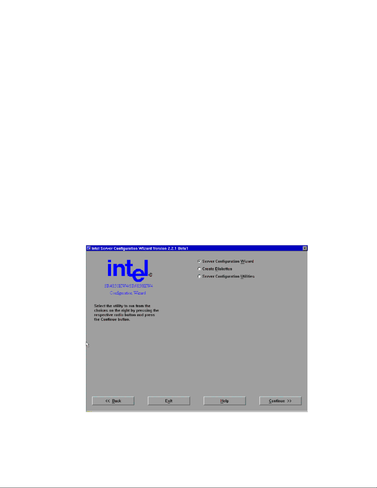
Server Platform Utilities
The SCW does not perform the following functions:
Install and / or update the BIOS.
Install and / or update the firmware.
The SCW and Intel® Server Management (ISM) can each be used to configure the firmware on the
server, but these items only need to be configured once. If you are installing the Intel® Server
Management software on this server, you do not need to use the SCW to configure LAN channel 1,
the serial channel, or users. The Intel® Server Management software will allow you to configure
these items later, from the operating system. The SCW will ask you if you are using Intel® Server
Management software and not prompt you to configure these items if you are using Intel® Server
Management.
On some screens in the SCW application, you can choose multiple entries. These selection options
have square check-boxes, not round radio selection buttons. When multiple selections are
permitted, the SCW will configure each item you select.
Some options require other options to be selected. In these cases, the SCW automatically selects the
options required for the options that you selected. The reverse is also true. If an option is
unchecked, then all options dependent on that option are automatically unchecked.
Starting the System Configuration Wizard
To run the SCW, boot your server from the Intel® Server Platforms SR4850HW4 and SR6850HW4
Deployment Toolkit CD. The Start screen provides a brief description of the Server Configuration
Wizard.
Figure 24. System Configuration Wizard Start Screen
82 Intel® Server Platforms SR6850HW4 and SR6850HW4/M Product Guide
Page 83

This screen gives you the following options, from which you can choose one:
Server Configuration Wizard: The Server Configuration Wizard presents a series of screens,
allowing the setup of the server to be either almost hands-off for the beginner, or nearly as
detailed as using the Server Platform Setup Utility for an expert user. The SCW can also run in
a silent mode of operation, where you provide a previously saved server configuration file on a
floppy diskette that the SCW uses to configure the server.
Create Diskettes: Select the Create Diskettes option to create diskettes that are used to do
utility installations and perform device driver installations.
Server Configuration Utilities: The Server Configuration Utilities button allows you to
manually set up the server configuration using specific software utilities that will set up the
BMC parameters.
Select the appropriate action and click Continue. The following sections walk through the screens
you will see following the selection of each of these options.
Using the Server Configuration Wizard Option
When the SCW starts, it checks the status of the server to determine what questions it needs to
query the user for to properly configure the system. To do this, SCW probes the server for the
following:
Main board
FRU devices
SDRs
Chassis type
Firmware version
BIOS version
Channels
Users
Advanced Feature Support
After the probe is complete, the SCW leads you through screens that ask for information about the
server. When all of the information has been gathered, the SCW asks for the permission to
complete the server configuration. It stores the configuration information in non-volatile memory
and it configures the BIOS and the BMC.
The SCW asks first if Intel® Server Management is installed on this server. If you select Yes, the
SCW does not ask you about configuring LAN channel 1, the serial channel, or users. If you select
No, you are given the option to configure these items through the SCW. The SCW continues by
asking you to choose to configure the FRUs, SDRs, the System Asset Tag, remote management and
advanced features (if the Intel® Management Module - Advanced Edition is installed). See the
following figure.
83
Page 84
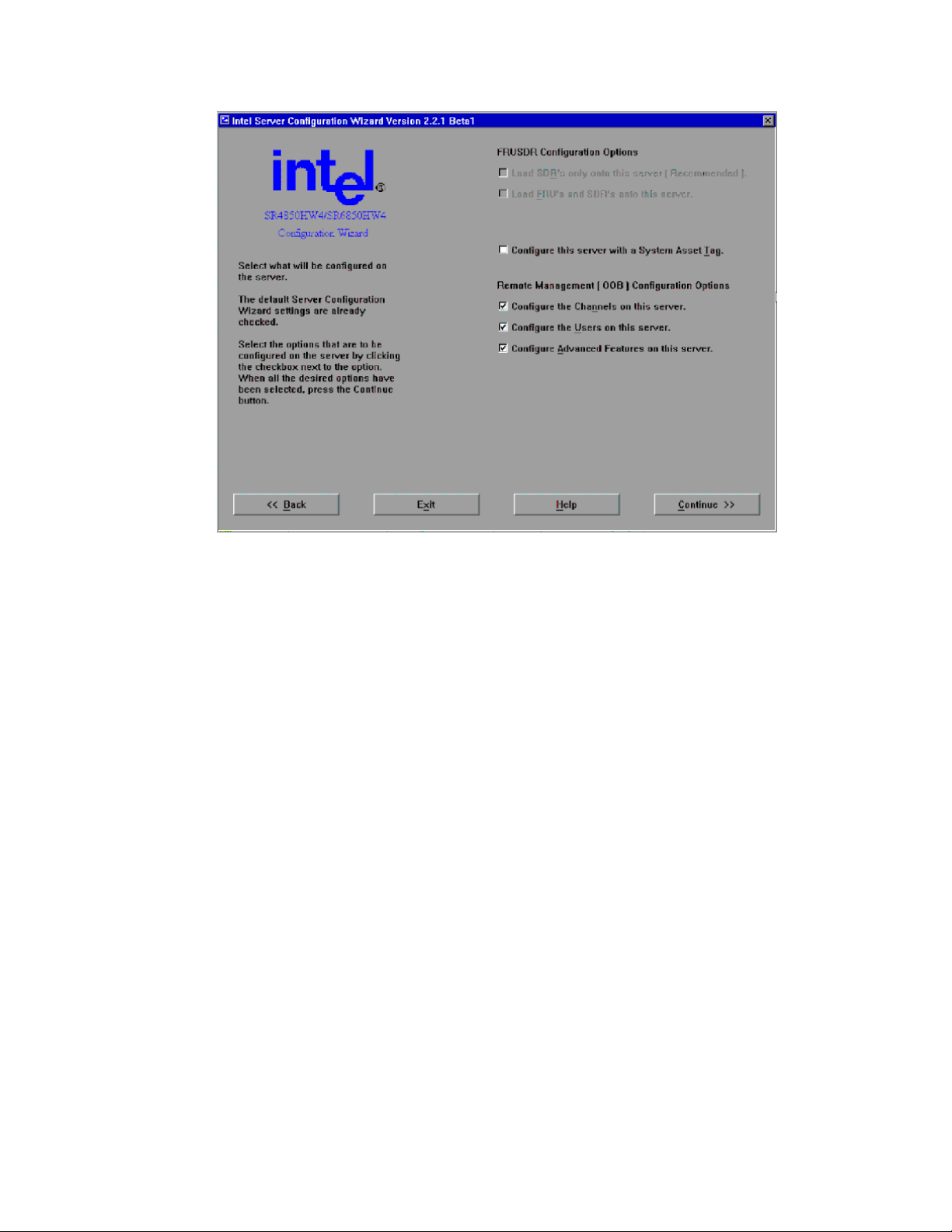
Server Platform Utilities
Figure 25. Configuration Options
Load SDRs only onto this server: When this box is checked, the SCW will ask you questions
about the SDRs and will load them based on how you answer those questions.
Load FRUs and SDRs onto this server: The FRUs and SDRs are loaded based on the
®
master.cfg file found in the \FRUSDR folder in the Intel
Server Platforms SR4850HW4 and
SR6850HW4 Deployment Toolkit CD.
Configure this server with a System Asset Tag: When this box is checked, the SCW will ask
you questions about the system asset tag to assign to the system.
Configure the Channels on this server: The Configure Channels checkbox allows you to
configure the various channels available on the server.
Configure the Users on this server: The Configure Users checkbox allows you to configure
the users supported on this server.
Configure Advanced Features on this server: The Configure Advanced Features checkbox
allows you to configure the Advanced Features of an Intel® Management Module – Advanced
Edition system configuration. This option is available only on a system that uses the Intel®
Management Module – Advanced Edition.
®
If your server has the Intel
Management Module – Professional Edition installed, the following
options are included by default:
Load FRUs and SDRs onto this server
Configure Channels on this server
Configure Users on this server
84 Intel® Server Platforms SR6850HW4 and SR6850HW4/M Product Guide
Page 85

If your server has the Intel® Management Module – Advanced Edition installed, the following
options are included by default:
Load FRUs and SDRs onto this server
Configure Channels on this server
Configure Users on this server
Configure Advanced Features on this server
After you decide which of the options to program and press the Continue button, the SCW will exit
from the graphical user interface mode and begin programming the options. If you do not select any
options, the SCW will exit.
Selecting or deselecting options on this screen does not affect the existing state of the options on
the server. If you check an option, it only implies that you intend to configure it. If you do not
select an option, it only implies that you do not want to make any changes to that option while
using SCW; it does not disable the option on the server.
After you press Continue, you are brought to a screen on which you need to set the date and time on
the server. The date and time are saved as soon as you press Continue. This screen also shows you
the versions of the HSC, firmware, and BIOS that are installed on the server.
Configuring SDRs and FRUs
Sensor Data Records (SDRs)
Before the Sensor Data Records can be loaded, you must provide information about your server.
This information is gathered through a series of screens. The actual questions differ depending on
the configuration of the server. You might be asked for the type of main board, the chassis, and the
type and number of fans that are in the platform.
Field Replaceable Units (FRUs)
Each server comes with the FRUs pre-programmed, but you may want to refresh them from a
current Intel
supports loading ASCII FRU data from a file similar to the FRUSDR Load Utility’s
MASTER.CFG file. This file is called SCW_<platform>.CFG. The file is modified to remove
many of the prompt text entries of the MASTER.CFG file so that the SCW can go directly to the
pertinent hardware-specific questions you will need to answer. The SCW will refresh the FRUs
when the option “Load FRUs and SDRs onto this server” is selected.
®
Server Platforms SR4850HW4 and SR6850HW4 Deployment Toolkit CD. The SCW
85
Page 86

Server Platform Utilities
Configuring Channels
The Channels configuration screen provides a way for you to configure the various channels in the
system. If your server has the Intel
channel, and one serial modem channel are supported. If your server has the Intel
®
Management Module – Professional Edition, one LAN
®
Management
Module – Advanced Edition, your server supports one LAN channel, one serial modem channel,
and one advanced LAN channel.
Figure 26. Channels Configuration Screen
The LAN Channel configuration provides a way to configure the individual LAN channel(s) on the
system. The configuration of each LAN channel is spread across several configuration screens.
Configure LAN Channel 1 on this server: The Configure LAN Channel 1 checkbox allows
you to configure LAN Channel 1. LAN channel 1 is available regardless of the version of the
Intel® Management Module that is installed.
Configure Serial/Modem Channel on this server: The Configure Serial/Modem Channel
checkbox allows you to configure Serial/Modem Channel.
Configure Advanced IMM LAN Channel on this server: The Advanced IMM LAN Channel
®
checkbox allows user to configure the Intel
available only on the Intel
®
Management Module – Advanced Edition.
Management Module LAN channel. This option is
86 Intel® Server Platforms SR6850HW4 and SR6850HW4/M Product Guide
Page 87
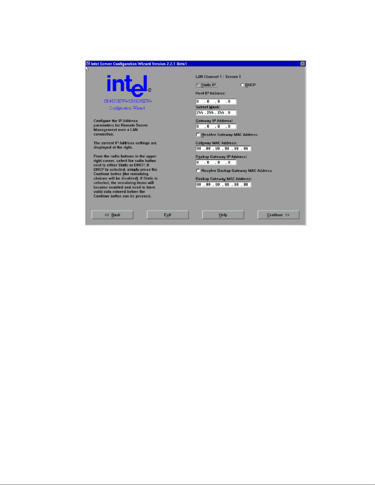
LAN Channel Configuration Screen 1 – LAN IP Setup
Figure 27. LAN Channel Setup Screen 1
When this screen is displayed, the settings shown are the current settings for this LAN channel on
the server. Unless otherwise noted, all fields on this screen must have valid data entered into them.
The Continue button is disabled/grayed out until all of the edit boxes on the screen are filled in.
Static IP: The Static IP radio button allows you to manually set the Host IP Address, the
Subnet Mask, the Gateway IP Address and the Backup Gateway IP Address. The Backup
Gateway IP Address field can be left blank.
DHCP IP: The DHCP radio button enables the dynamic host configuration protocol to allow
the server to automatically assign the host IP address, router IP address and subnet mask. If the
DHCP radio button is selected, the Host IP Address, Subnet Mask, Gateway IP Address, and
Backup Gateway IP Address edit boxes are disabled. These values are assigned by the DHCP
server.
Host IP Address: The Host IP Address edit box allows you to enter the host IP address for this
LAN channel. The Host IP Address is the Logical or Internet Address of the server. The Host
IP Address accepts is entered as a dotted decimal IP address, such as 192.168.0.2. This option
is available only if Static IP is selected.
Subnet Mask: The Subnet Mask edit box allows you to enter the subnet mask for this LAN
channel. The Subnet Mask is the logical or Internet address of the host’s subnet. The server
uses this to decide if the alert destination is in the local subnet or in another subnet relative to
the server. The Subnet Mask IP address is entered as a dotted decimal IP address, such as
255.255.255.0. This option is available only if Static IP is selected.
87
Page 88
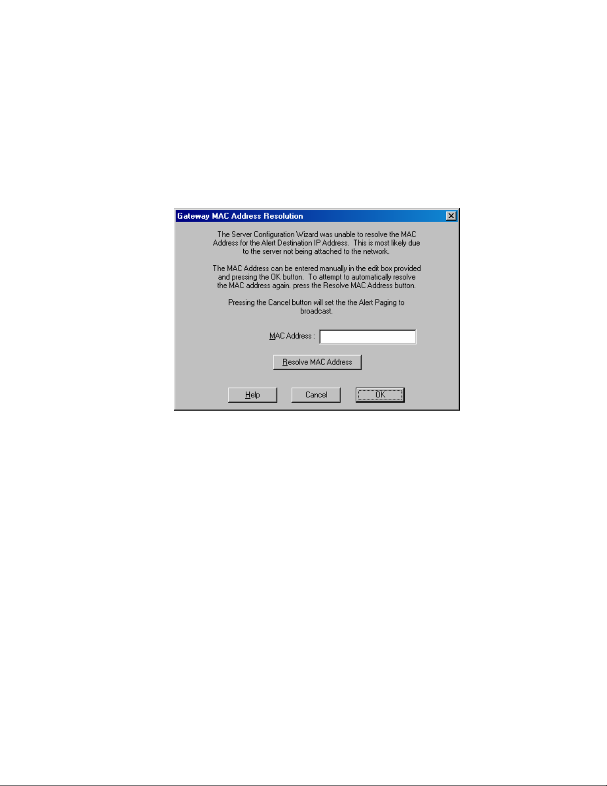
Server Platform Utilities
Gateway IP Address: The Gateway IP Address edit box allows you to enter the Gateway IP
address for this LAN channel. The Gateway IP Address is the logical or Internet address of the
router. The Gateway IP Address is entered as a dotted decimal IP address, such as 10.0.0.254.
This option is available only if Static IP is selected.
Resolve Gateway MAC Address: The Resolve Gateway MAC Address checkbox, when
checked, instructs the SCW to attempt to automatically resolve the MAC address for the
server’s IP address. You can enter an address here only if Static IP is selected.
If the Gateway MAC address cannot be resolved by the server’s IP Address that you entered, the
SCW displays the following dialog, which allows you to enter a MAC address.
Figure 28. Gateway MAC Address Resolution
MAC Address: Use the MAC Address edit box to enter the Gateway MAC address for the
server’s IP address, if it is known. As an alternative, you can select Resolve MAC Address. If
neither of these options is right for your circumstances, you can disregard both and click OK, in
which case, alerts are broadcast.
Resolve MAC Address: Resolve MAC Address is used to attempt to resolve the MAC address
for the server’s IP address. Press this button if the resolution attempt failed because the server
was not connected to the network.
You will see the same dialog box when resolving the Backup Gateway MAC Address.
88 Intel® Server Platforms SR6850HW4 and SR6850HW4/M Product Guide
Page 89

LAN Channel Configuration Screen 2 –Server Management and Serial Over LAN Setup
This screen allows you to continue to enter the necessary settings to configure the specified LAN
channel.
Figure 29. LAN Channel Setup Screen 2
When this screen is displayed, the settings shown are the current settings for this LAN channel on
the server. The continue button is enabled at all times on this screen.
Enable LAN Access: Enable LAN Access allows you to enable or disable the LAN access for
the server. When checked, all of the LAN access parameters are enabled and you can set them
to the appropriate values. When not checked, all of the LAN access parameters on this page are
disabled. The state of this option also determines whether Serial Over LAN (SOL) can be set
up. If this option is disabled, SOL cannot be configured and the Enable Serial Over LAN
checkbox is disabled.
LAN Privilege Level Limit: Privilege Level Limit dropdown list allows you to select a
privilege limit for the channel that is being configured. This privilege level takes precedence
over the user privilege limit. If a channel privilege level is set at User level, for example, then
users can only execute user-level commands, even if the user privilege level is set higher than
User. The meanings of the different privilege level limits are explained below.
89
Page 90

Server Platform Utilities
User: Only “benign” commands are allowed. These are primarily commands that read data
structures and retrieve status. Commands that can be used to alter BMC configuration, write
data to the BMC or other management controllers, or perform system actions such as resets,
power on/off, and watchdog activation are disallowed.
Operator: All BMC commands are allowed, except for configuration commands that can
change the behavior of the out-of-band interfaces. For example, Operator privilege does not
allow the capability to disable individual channels, or change user access privileges.
Administrator: All BMC commands are allowed, including configuration commands. An
administrator can even execute configuration commands that would disable the channel that the
Administrator is communicating over.
Enable Serial Over LAN: Allows you to enable or disable the SOL access for the server.
When checked, all of the SOL access parameters are enabled and you can set them to the
appropriate values. When not checked, all of the SOL access parameters on this page are
disabled.
Serial Over LAN Privilege Level Limit: The SOL Privilege Level Limit dropdown list allows
you to set the SOL privilege level that is required to be able to activate SOL mode using the
Activate SOL command. This privilege level takes precedence over the user privilege limit. If
the privilege level is set at User level, for example, then users can only execute user-level
commands, even if the user privilege level is set higher than User. The possible privilege level
choices are the same as the LAN Privilege levels.
SOL Number of Retries: The SOL Number of Retries edit box allows you to enter the number
of connection retries permitted while attempting access in SOL mode. The valid range is from
one to seven.
SOL Retry Interval: The SOL Retry Interval edit box allows you to enter a number for
specifying the interval between two retries while attempting access in SOL Mode. The valid
range is from one to 255.
SOL Baud Rate: The SOL Baud Rate dropdown list allows you to set SOL baud rate desired.
The valid choices are 9600bps, 19.2kbps, 38.4kbps, 57.6kbps or 115.2kbps.
90 Intel® Server Platforms SR6850HW4 and SR6850HW4/M Product Guide
Page 91

LAN Channel Configuration Screen 3 – LAN Alerting Set u p
This screen allows you to continue to enter the necessary settings to configure the specified LAN
channel.
Figure 30. LAN Channel Setup Screen 3
Enable LAN Alerting: Allows you to configure the LAN alert settings for this LAN channel
on the server. The availability of all settings on this display depends on the setting of this
checkbox.
Alert Destination Console 1 IP Address: Allows you to enter the first alert destination IP
address for this LAN channel. The Alert IP Address is the logical or Internet address of the
Alert-Destination. In case of single node destination, this is the unicast or specific IP address.
This is the IP Subnet address if the alert needs to be broadcast within a particular subnet. The IP
is entered as a dotted decimal IP, such as 192.168.0.2.
Resolve Alert Destination 1 MAC Address: Instructs the SCW to resolve the MAC address of
the first alert destination IP address. If the Alert Destination MAC address cannot be resolved,
then the SCW will display a dialog that allows you to enter in a MAC address. A final option
would be to continue, which would result in alerts being sent via broadcast.
Alert Destination 1 MAC Address: The Alert Destination MAC Address is the physical or the
Ethernet address of the Alert Destination. It corresponds to the Alert Destination IP Address.
The MAC address is entered as six dotted hexadecimal bytes, such as 3e.4d.ab.12.c3.23
Alert Destination Console 2 IP Address: The Alert Destination Console 2 IP Address edit
box allows you to enter the IP address for the second alert destination for this LAN channel. In
91
Page 92

Server Platform Utilities
case of single node destination, this is the unicast or specific IP address. This is the IP Subnet
address if the alert needs to be broadcast within a particular subnet.
Resolve Alert Destination 2 MAC Address: The Resolve Alert Destination 2 MAC Address
checkbox, if enabled, instructs the SCW to attempt to automatically resolve the MAC for this
LAN channel. If the Alert Destination 2 MAC address cannot be resolved, then the SCW will
display a dialog, which allows you to enter a MAC address. A final option would be to
continue, which would result in alerts being sent via broadcast.
Alert Destination 2 MAC Address: The Alert Destination 2 MAC Address edit box allows
you to enter the MAC address for the second alert destination on this LAN channel. The Alert
Destination MAC Address is the physical or the Ethernet address of the Alert Destination. It
corresponds to the Alert Destination IP Address. The MAC address is entered as six dotted
hexadecimal bytes, such as 3e.4d.ab.12.c3.23
SNMP Community String: The SNMP Community String edit box allows you to enter the
community field in the Header section of the SNMP trap sent for a LAN alert. If a string is not
set on the server, then the SCW will display and set the string as public. The string must be
from 5 – 18 characters long.
LAN Alert Filters: If you press the LAN Alert Filters button, the SCW will display the
following screen with which you can check the filters that are to be used when sending out
alerts.
No Email Alerts: The No Email Alerts Radio Button allows you to specify that none of the
alerts that may be configured are to go to any configured email addresses. This is the default
setting in Intel® Management Module– Professional Edition system configurations, and cannot
be changed on these system configurations.
Send Email Alerts via LAN Alert IP Address 1: The Send Email Alerts via LAN Alert IP
Address 1 radio button allows you to specify that all LAN alerts configured to go the first alert
IP address are instead to be sent as emails. This option is available only on the Intel®
Management Module– Advanced Edition system configuration.
Send Email Alerts via LAN Alert IP Address 2: The Send Email Alerts via LAN Alert IP
Address 2 radio button allows you to specify that all LAN alerts configured to go the second
alert IP address are instead to be sent as email messages. This option is available only on the
Intel® Management Module– Advanced Edition system configuration.
92 Intel® Server Platforms SR6850HW4 and SR6850HW4/M Product Guide
Page 93

The next screen displayed allows you to select the type of alert to receive:
Figure 31. Configuring LAN Alert Filters
Select All Button: This button will select all of the filter checkboxes on the dialog.
Clear All: This button will clear all of the filter checkboxes on the dialog.
Configuring the Serial/Modem Channel
The Serial/Modem channel option is available on both the Intel® Management Module–
Professional Edition and Intel® Management Module– Advanced Edition system configurations.
The Serial/Modem Connection configuration section provides the mechanism to configure the
serial/modem channel that is present on the system. The configuration of the serial/modem channel
is spread across several configuration screens. The first screen sets data specific to configuring the
modem. The second screen sets data specific to the access modes. The last screen sets data specific
to paging, if paging is desired on the server.
93
Page 94

Server Platform Utilities
Serial/Modem Configuration Screen 1 – Modem Setup
When the screen comes up, the settings displayed are the current setting on for the serial/modem
channel on the server. All fields on this screen are required to have valid data entered. The
Continue button is disabled/grayed out until all of the edit boxes on the screen above have data
entered.
Figure 32. Modem Configuration
ESC Sequence: The ESC Sequence edit box allows you to enter the escape sequence string for
the modem. The string is sent to the modem before sending a command string to the modem.
The edit control will limit the number of characters that can be entered for the ESC Sequence
string to five.
Hangup String: The Hangup Line edit box allows you to enter the hangup ling string. This
string is sent to the modem whenever the EMP wants to terminate the session. The EMP
automatically sends an <Enter> character after this string. The edit control will limit the
number of characters that can be entered for the Hangup String to eight.
Modem Init String: The Modem Init String edit box allows you to enter the modem
initialization string. This string is transmitted every time a serial/modem connection is
initialized. The string length of the Modem Init String is determined at run time and the edit
control will limit the number of characters that can be entered to that value.
Modem Dial Command: The Modem Dial Command edit box allows you to enter the modem
dial command string. This string is transmitted every time a Platform Event Page is sent. This
string is sent before the paging string to indicate to the modem how to dial.
94 Intel® Server Platforms SR6850HW4 and SR6850HW4/M Product Guide
Page 95

Serial/Modem Configuration Screen 2 - Configuring Remote Server Management Options for a Serial / Modem Connection
This screen allows you to continue to enter the necessary settings to configure the serial/modem
channel.
Figure 33. Remaining Serial/Modem Configuration Parameters
Enable Access: The Enable Access checkbox allows you to enable or disable Serial/Modem
connectivity. When checked, all of the Serial/Modem parameters are enabled and you can set
them to the appropriate values. When not checked, all of the Serial/Modem parameters on this
page are disabled.
Serial Privilege Level: The Serial Privilege Level dropdown list allows you to select a
privilege limit for the serial channel. This privilege level takes precedence over the user
privilege limit. If the privilege level is set at User level, for example, then users can only
execute user-level commands, even if the user privilege level is set higher than User. The
possible privilege level choices are the same as the LAN Privilege levels.
Connection Mode: The Connection Mode combo allows you to configure the method to
connect to the Serial/Modem connectivity. The valid choices are:
- Direct Connect: For applications that connect to the serial/modem port directly to another
computer system.
- Modem Mode: For applications where the serial/modem port is connected to an external
modem.
95
Page 96
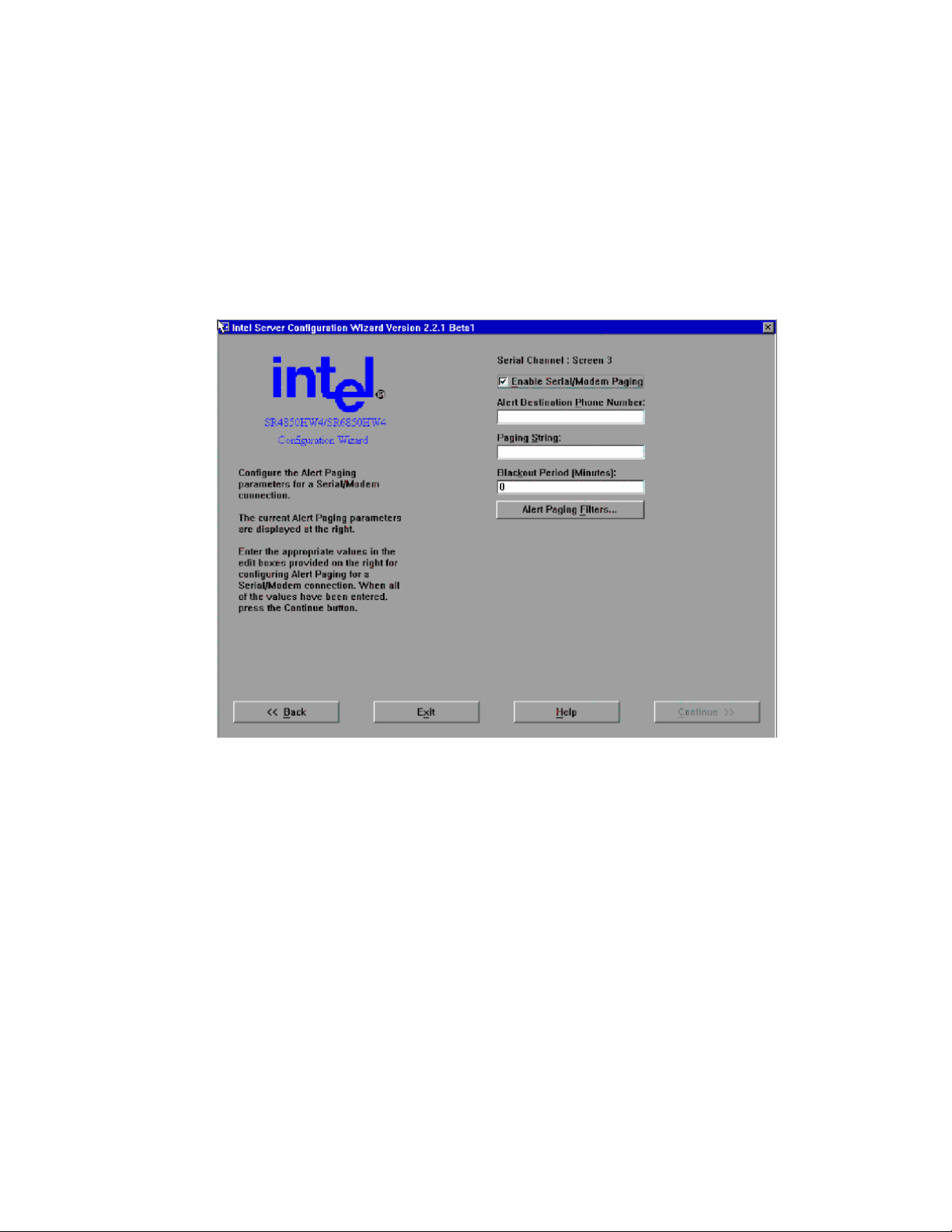
Server Platform Utilities
System Phone Number: The System Phone Number edit box allows you to enter the phone
number used to connect to this system. The length of the phone number allowed is determined
at run time. The SCW will limit the number of characters that can be entered at runtime.
Serial/Modem Configuration Screen 3 - Configuring Alerting over a Serial/Modem Connection
This screen allows you to continue to enter the necessary settings to configure the serial/modem
channel. The Continue button is disabled/grayed out until all edit boxes on the screen have data
entered.
Figure 34. Configuring Serial Alerts
Enable Serial/Modem Paging Checkbox: The Enable Serial/Modem Paging checkbox allows
you to enable Serial/Modem paging. When checked, the remaining controls on this screen are
also enabled so that Serial/Modem paging can be configured. If this checkbox is cleared, all
controls are disabled and Serial/Modem paging shall be disabled on the server.
Alert Destination Phone Number Edit Box: The Alert Destination Phone Number edit box
allows you to enter the phone number of the system that is to receive Alerts through a
serial/modem connection.
Paging String Edit Box: The Paging String edit box allows you to enter the paging string that
contains the characters that are sent once the connection has been made. The length of the
Paging String is determined at run time. The paging string is concatenated with the Alert
Destination Phone Number entered on this screen. Therefore, it is not necessary to enter the
Alert Destination Phone Number with the Paging String.
96 Intel® Server Platforms SR6850HW4 and SR6850HW4/M Product Guide
Page 97
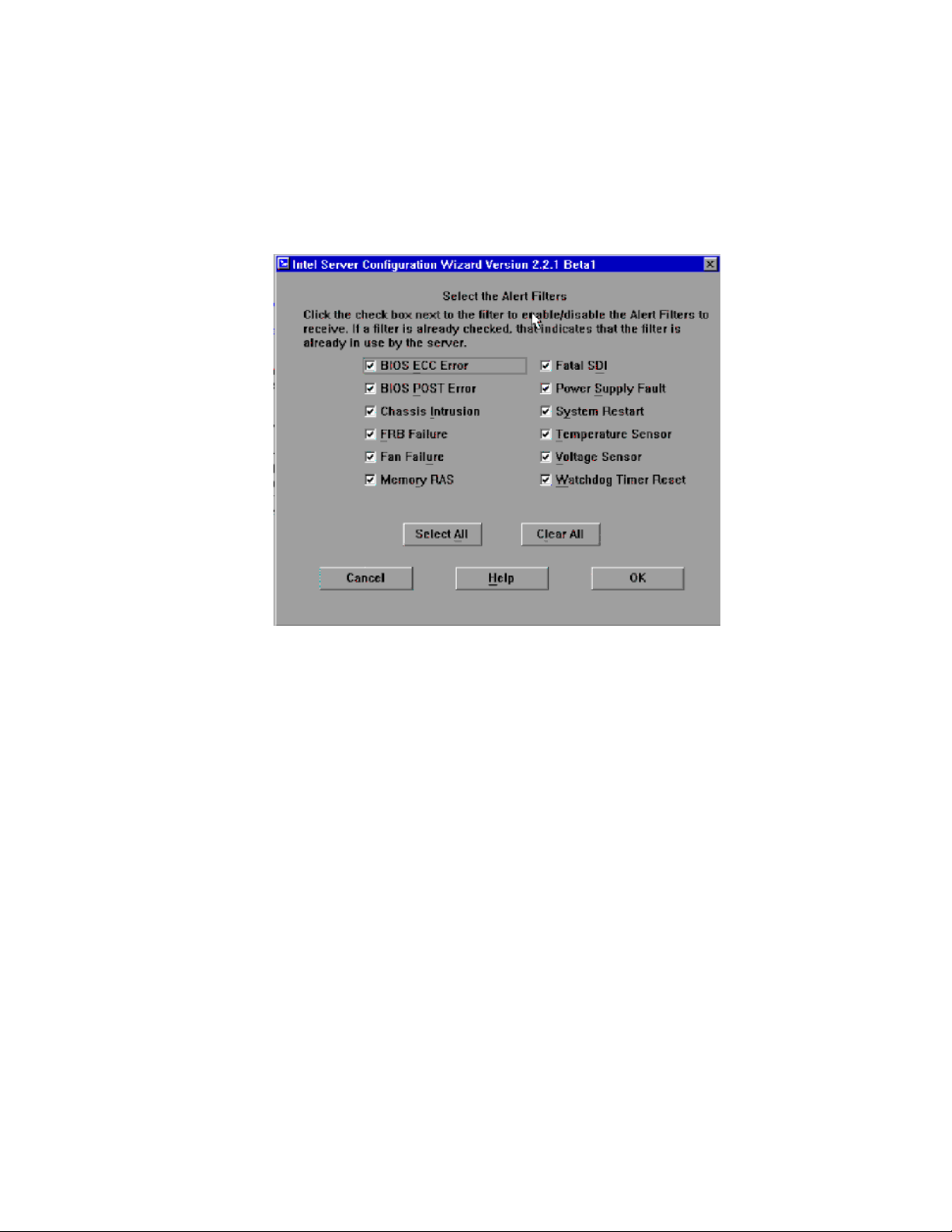
Blackout Period Edit Box: The Blackout Period edit box allows you to enter the time, in
minutes, between successive pages. The valid range is [0 – 255] where 0 disables the blackout
period.
Alert Paging Filters: If you press the Alert Paging Filters button, the SCW will display the
following screen with which you can check the filters that are to be used when sending out
alerts.
Figure 35. Configuring Serial Alert Filters
LAN Channel Configuration Screen 3 – LAN Alerting Setup”, page 91, for information about
See “
this screen.
97
Page 98

Server Platform Utilities
Select Users to Configure Screen
The Configure Users Screen provides a mechanism for configuring user access to LAN and
Serial/Modem channels. A maximum of four users are supported by the Intel® Server Platforms
SR6850HW4 and SR6850HW4/M. The screens allow configuration of user settings like username,
password, and the per-channel configuration for each user. These options are available on both the
Intel® Management Module – Professional Edition and the Intel® Management Module –
Advanced Edition system configurations.
Figure 36. User Configuration Selection Screen
Configuring the User 1 [Anonymous User] on this server: If you select this box, you will be
presented screens to configure the anonymous user.
Configuring User 2 on this server: If you select this box, you will be presented screens to
configure the second user.
Configuring User 3 on this server: If you select this box, you will be presented screens to
configure the third user.
Configuring User 4 on this server: If you select this box, you will be presented screens to
configure the fourth user.
Select All: If you click this button, all of the above options are selected. Use this if you want to
configure all four users. This button is available only if all of the users are configurable.
Clear All: If you click this button, all of the above options are de-selected. This button is
available only if all of the users are configurable.
98 Intel® Server Platforms SR6850HW4 and SR6850HW4/M Product Guide
Page 99
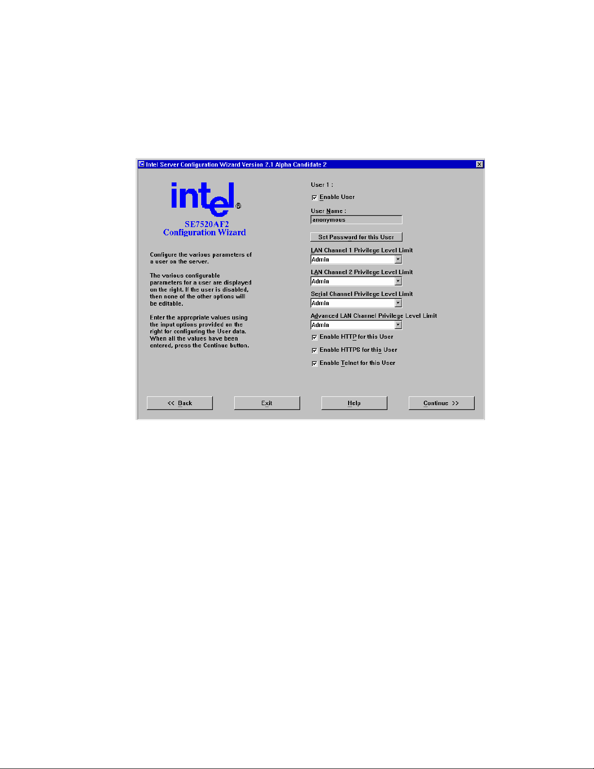
Configure Users Screen
The Configure Users Screen provides a mechanism for configuring user access to LAN and
Serial/Modem channels. The maximum number of users that can be configured for a system
depends on that system. The screens allow configuration of user settings like username, password,
and the per-channel configuration for each user.
Figure 37. User Configuration Screen
Enable User: The Enable User checkbox allows you to enable or disable this user. When the
checkbox is enabled, all other configuration items for this user become enabled.
Username: The Username edit box is used to allow a custom name to be assigned to a user
configuration. For User 1, the name must be set to Anonymous. Therefore, this option is
disabled for User1.
Set Password for this User: The Set Password button displays a dialog box that allows a
password to be set for the selected user.
LAN Channel 1 Privilege Level Limit: The LAN Channel 1 Privilege Level Limit list allows
you to select the privilege level for the user being configured. The global privilege level set for
LAN channel access takes precedence over the user privilege level. For example, if the LAN
channel is configured for user access only, then users are limited to user operations regardless
of the user privilege level.
LAN Channel 2 Privilege Level Limit: The LAN Channel 2 Privilege Level Limit dropdown
list allows you to select the privilege level the user being configured.
99
Page 100

Server Platform Utilities
Serial Channel Privilege Level Limit: The Serial Channel Privilege Level dropdown list
allows you to select the privilege level for the serial/modem channel access of the user being
configured.
Advanced LAN Channel Privilege Level Limit: The Advanced LAN Channel Privilege Level
dropdown list allows you to select the privilege level for the Advanced IMM LAN channel
®
access for the user being configured. This option is available only on the Intel
Management
Module – Advanced Edition system configuration.
Enable HTTP for this User: The Enable HTTP for this User checkbox is provided to Enable
HTTP feature for this user on the Advanced IMM LAN Channel. This option is available only
on the platform configuration that uses the Intel
®
Management Module – Advanced Edition.
Enable HTTPS for this User: The Enable HTTPS for this User checkbox is provided to
Enable HTTPS feature for this user on the Advanced IMM LAN Channel. This option is
®
available only on the platform configuration that uses the Intel
Management Module –
Advanced Edition.
Enable Telnet for this User: The Enable Telnet for this User checkbox is provided to Enable
Telnet feature for this user on the Advanced IMM LAN Channel. This option is available only
on the platform configuration that uses the Intel
®
Management Module – Advanced Edition.
100 Intel® Server Platforms SR6850HW4 and SR6850HW4/M Product Guide
 Loading...