

Page 1

Intel® Server System SR2612UR
Service Guide
A Guide for Technically Qualified Assemblers of Intel® Identified Subassemblies/
Products
Intel Order Number E76206-004
Intel® Server System SR2612UR Service Guide i
Page 2

Disclaimer
Information in this document is provided in connection with Intel® products. No license, express or implied, by
estoppel or otherwise, to any intellectual property rights is granted by this document. Except as provided in Intel's
Terms and Conditions of Sale for such products, Intel assumes no liability whatsoever, and Intel disclaims any
express or implied warranty, relating to sale and/or use of Intel products including liability or warranties relating to
fitness for a particular purpose, merchantability , or infringement of any patent, copyright or other intellectual property
right. Intel products are not designed, intended or authorized for use in any medical, life saving, or life sustaining
applications or for any other application in which the failure of the Intel product could create a situation where
personal injury or death may occur. Intel may make changes to specifications and product descriptions at any time,
without notice.
Intel server boards contain a number of high-density VLSI and power delivery components that need adequate
airflow for cooling. Intel's own chassis are designed and tested to meet the intended thermal requirements of these
components when the fully integrated system is used together. It is the responsibility of the system integrator that
chooses not to use Intel developed server building blocks to consult v endor datasheets and operating parameters to
determine the amount of airflow required for their specific application and environmental conditions. Intel Corporation
can not be held responsible if components fail or the server board does not operate correctly when used outside any
of their published operating or non-operating limits.
Intel, Intel Pentium, and Intel Xeon are trademarks or registered trademarks of Intel Corporation or its subsidiaries in
the United States and other countries.
* Other names and brands may be claimed as the property of others.
Copyright © 2010, Intel Corporation. All Rights Reserved
ii Intel® Server System SR2612UR Service Guide
Page 3

Preface
About this Manual
Thank you for purchasing and using the Intel® Server System SR2612UR. This guide
assumes you are familiar with Serial ATA (SATA) technology, SAS (Serial Attached
SCSI), computer hardware, data storage, and network administration terminology and
tasks.
This manual is written for system technicians who are responsible for troubleshooting,
upgrading, and repairing this server system. This document provides reference
information, feature information, and step-by-step instructions for adding and replacing
components in the server system. For the latest version of this manual, see
http://www.intel.com/support/motherboards/server/sr2612ur/.
Terminology Used in this Guide
Because this guide provides information that you can use to manage one or more storage
appliances in a variety of configurations, the generic term “storage system” is used to refer
to the controller, disk drives, JBOD expansion enclosures, and servers being used together
for data storage.
Many of the terms and concepts referred to in this guide are known to computer users by
multiple names. In this guide, this terminology is used:
• Controller (also known as an I/O module or I/O controller)
• Disk drive (also known as hard disk, hard drive, or hard disk drive including Drive
Carrier Assembly)
• HBA (also known as Host Bus Adapter, RAID controller/adapter, or SAS/SATA
Adapter)
• Storage Application Array (also known as an Intel
®
Server System SR2612UR)
Manual Organization
Chapter 1 provides information on the contents of each server system and a list of
reference resources. This includes a list of all technical documents that provide additional
details on the Intel
Intel® Server System SR2612UR Service Guide iii
®
Server System SR2612UR, and the location where they can be found.
Page 4

Chapter 2 describes the features of your Intel® Server System SR2612UR and shows you
how you can upgrade your system as your storage requirements change. It also lists the
contents of the storage application array package, and describes additional hardware
requirements.
Chapter 3 provides instructions for adding and replacing components. It provides step-bystep instructions and diagrams for installing or replacing components such as the fans,
power supply, drives, and other components.
Chapter 4 describes the status and activity LEDs that help you monitor the overall status
of your Intel
®
Server System SR2612UR.
Chapter 5 provides instructions on using the utilities that are shipped with the board or
that may be required to update the system. This includes information for navigating
through the BIOS Setup screens, performing a BIOS update, and resetting the password or
BIOS defaults.
The back of this manual provides technical specifications, regulatory information,
“getting help” information, and the warranty.
iv Intel® Server System SR2612UR Service Guide
Page 5

Safety Information
重要安全指导
在执行任何指令之前,请阅读本文件中的所有注意事项及安全声明。并参阅http://www.intel.
com/support/motherboards/server/sb/cs-010770.htm上的
Intel Server Boards and Server
Chassis Safety Information
(《Intel 服务器主板与服务器机箱安全信息》)。
Before you begin the assembly process, you will need to make sure you follow certain
basic safety precautions.
Important Safety Instructions
Read all caution and safety statements in this document before performing any of the
instructions. See also Intel Server Boards and Server Chassis Safety Information on the
®
Server Deployment Toolkit 3.0 CD and/or at
Intel
http://www.intel.com/support/motherboards/server/sb/cs-010770.htm
Wichtige Sicherheitshinweise
Lesen Sie zunächst sämtliche Warn- und Sicherheitshinweise in diesem Dokument, bevor
Sie eine der Anweisungen ausführen. Beachten Sie hierzu auch die Sicherheitshinweise zu
Intel-Serverplatinen und Servergehäusen auf der Intel
oder unter http://www.intel.com/support/motherboards/server/sb/cs-010770.htm
®
Server Deployment T oolkit 3.0 CD
Consignes de sécurité
Lisez attention toutes les consignes de sécurité et les mises en garde indiquées dans ce
document avant de suivre toute instruction. Consultez Intel Server Boards and Server
Chassis Safety Information sur le Intel
rendez-vous sur le site
http://www.intel.com/support/motherboards/server/sb/cs-010770.htm Instrucciones de
seguridad importantes
Lea todas las declaraciones de seguridad y precaución de este documento antes de realizar
cualquiera de las instrucciones. Vea Intel Server Boards and Server Chassis Safety
Information en el Intel
http://www.intel.com/support/motherboards/server/sb/cs-010770.htm
®
Server Deployment Toolkit 3.0 CD y/o en
Intel® Server System SR2612UR Service Guide v
®
Server Deployment Toolkit 3.0 CD ou bien
Page 6

Warnings
Heed safety instructions: Before working with your server product, whether you are
using this guide or any other resource as a reference, pay close attention to the safety
instructions. You must adhere to the assembly instructions in this guide to ensure and
maintain compliance with existing product certifications and approvals. Use only the
described, regulated components specified in this guide. Use of other products /
components will void the UL listing and other regulatory approvals of the product and
will most likely result in noncompliance with product regulations in the region(s) in which
the product is sold.
System power on/off: The power button DOES NOT turn off the system AC power. To
remove power from the system, you must unplug the AC power co rd from the wal l outlet.
Make sure the AC power cord is unplugged before you open the chassis, and add or
remove any components.
Hazardous conditions, devices and cables: Hazardous electrical conditions may be
present on power, telephone, and communication cables. Turn off the server and
disconnect the power cord, telecommunications systems, networks, and modems attached
to the server before opening it. Otherwise, personal injury or equipment damage can
result.
Electrostatic discharge (ESD) and ESD protection: ESD can damage disk drives,
boards, and other parts. W e recommend that you perform all the procedures in this chapter
only at an ESD workstation. If one is not available, provide some ESD protection by
wearing an antistatic wrist strap attached to chassis ground any unpainted metal surface on
your server when handling parts.
ESD and handling boards: Always handle boards carefully. They can be extremely
sensitive to ESD. Hold boards only by their edges. After removing a board from its
protective wrapper or from the server, place the board component side up on a grounded,
static free surface. Use a conductive foam pad if available but not the board wrapper. Do
not slide board over any surface.
Installing or removing jumpers: A jumper is a small plastic encased conductor that slips
over two jumper pins. Some jumpers have a small tab on top that you can grip with your
fingertips or with a pair of fine needle nosed pliers. If your jumpers do not have such a tab,
take care when using needle nosed pliers to remove or install a jumper; grip the narrow
sides of the jumper with the pliers, never the wide sides. Gripping the wide sides can
damage the contacts inside the jumper, causing intermittent problems with the function
controlled by that jumper. Take care to grip with, but not squeeze, the pliers or other tool
you use to remove a jumper, or you may bend or break the pins on the board.
vi Intel® Server System SR2612UR Service Guide
Page 7

Contents
Preface ........................................................................................................................iii
About this Manual ................................................................................................................. iii
Terminology Used in this Guide ............................................................................................ iii
Manual Organization ............................................................................................................. iii
Safety Information ......................................................................................................v
Important Safety Instructions .................................................................................................v
Wichtige Sicherheitshinweise ................................................................................................v
Consignes de sécurité ...........................................................................................................v
Warnings ............................................................................................................................... vi
Chapter 1: Server System Contents and References .............................................1
Server System Contents ........................................................................................................1
Additional Information and Software ......................................................................................7
®
Server System SR2612UR Contents ..................................................................1
Intel
Disk Drive Specifications ...............................................................................................1
Cable Specifications ......................................................................................................1
Appliance Components and Features ...........................................................................2
About the Disk Drives and Drive Carriers ......................................................................3
Combining SATA and SAS Disk Drives .........................................................................5
Chapter 2: Server System Features ..........................................................................9
Server System Feature Overview ........................................................................................10
Server System Components ................................................................................................12
Server Board Components ..................................................................................................18
Front of Intel
SAS/SATA Midplanes ..........................................................................................................26
Hot-Swap SAS/SATA Backplane .........................................................................................27
RAID Support .......................................................................................................................28
Advanced Management Options .........................................................................................28
Rack Mount Options ............................................................................................................28
®
Intel
Server System SR2612UR Components ..........................................................14
®
Light-Guided Diagnostics ..................................................................................15
Intel
Configuration Jumpers ................................................................................................21
Peripheral Devices ......................................................................................................22
Control Panel ...............................................................................................................24
Active Midplane ...........................................................................................................26
Intel® Remote Management Module 3 ........................................................................28
®
Server System SR2612UR ...........................................................................22
Chapter 3: Hardware Installations and Upgrades .................................................29
Before You Begin .................................................................................................................29
Intel® Server System SR2612UR Service Guide vii
Page 8

Tools and Supplies Needed ........................................................................................29
System References .....................................................................................................29
Preparing for Installation ............................................................................................. 29
Installing Your Intel
®
Server System SR2612UR into a Rack (Optional) ............................30
Installing the Disk Drives .....................................................................................................33
Removing a Disk Drive Carrier Assembly (or Drive Blank) ................................................. 35
Important Safety Precautions ......................................................................................35
Removing a Disk Drive ................................................................................................35
Installing the Operating System .................................................................................. 37
Connecting Your Intel
®
Server System SR2612UR to a Host Server .................................38
Connecting to the 1GE iSCSI LAN Data Ports ............................................................38
Connecting Additional Enclosures ..............................................................................38
Powering On ...............................................................................................................38
Installing a 2.5-inch Internal Drive .......................................................................................39
DVD Installation ...................................................................................................................41
Replacing a Fan ..................................................................................................................43
Installing a Fan ....................................................................................................................44
Midplane Board Replacement .............................................................................................45
Memory Installation ..................................................................................................... 46
PCI Card and Battery Installation ........................................................................................48
Power Supply Replacement ................................................................................................51
Replacing the Backplane Board ..........................................................................................51
Removing the Backplane Board ..................................................................................52
Installing and Removing the RAID Battery Backup Unit ......................................................54
Installing the RAID Battery Backup Unit (BBU) ...........................................................54
Installing and Removing the Server Board ..........................................................................57
Removing the Server Board ........................................................................................57
Installing the Server Board ..........................................................................................60
Replacing the Backup Battery .............................................................................................62
Removing and Installing the Power Distribution Module .....................................................63
Removing the Power Distribution Module ................................................................... 63
Installing Power Distribution Module ........................................................................... 65
Chapter 4: Server Utilities ........................................................................................69
Using the BIOS Setup Utility ...............................................................................................69
Entering BIOS Setup ...................................................................................................69
If You Cannot Access Setup .......................................................................................69
Setup Menus ...............................................................................................................69
Upgrading the BIOS ............................................................................................................ 71
Preparing for the Upgrade ...........................................................................................71
Upgrading the BIOS ....................................................................................................72
Clearing the Password ........................................................................................................ 72
Restoring the BIOS Defaults ............................................................................................... 74
Appendix A: Drive Installation in the Drive Carrier ...............................................75
viii Intel® Server System SR2612UR Service Guide
Page 9

Introduction ..........................................................................................................................75
Installing a Disk Drive in a Universal Drive Carrier ......................................................75
Installing a Blank Insert in a Universal Drive Carrier ...................................................77
Appendix B: Intel® Server Issue Report Form .......................................................79
Appendix C: LED Decoder .......................................................................................85
Appliance Status ..................................................................................................................85
LED Status Board ........................................................................................................85
Monitoring the Disk Drives ...........................................................................................86
Audible Alarm ..............................................................................................................87
Appendix D: Getting Help ........................................................................................89
Warranty Information ...........................................................................................................89
Appendix E: Regulatory and Certification Information .........................................91
Product Regulatory Compliance ..........................................................................................91
Product Safety Compliance .........................................................................................91
Product EMC Compliance - Class A Compliance ........................................................92
Product Ecology Compliance ......................................................................................93
Certifications / Registrations / Declarations .................................................................93
Product Regulatory Compliance Markings ..................................................................95
Rack Mount Installation Guidelines .....................................................................................99
Power Cord Usage Guidelines ..........................................................................................100
Electromagnetic Compatibility Notices ..............................................................................101
FCC Verification Statement (USA) ............................................................................101
ICES-003 (Canada) ...................................................................................................102
CE Declaration of Conformity (Europe) .....................................................................102
VCCI (Japan) .............................................................................................................102
BSMI (Taiwan) ...........................................................................................................103
KCC (Korea) ..............................................................................................................103
Regulated Specified Components .....................................................................................103
Appendix F: Installation/Assembly Safety Instructions .....................................105
English ...............................................................................................................................105
Deutsch ..............................................................................................................................107
Français .............................................................................................................................109
Español ..............................................................................................................................112
Italiano ...............................................................................................................................115
System Specifications ...............................................................................................117
G Safety Information ..............................................................................................123
English ...............................................................................................................................123
Server Safety Information ..........................................................................................123
Safety Warnings and Cautions ..................................................................................123
Intended Application Uses .........................................................................................124
Site Selection .............................................................................................................124
Intel® Server System SR2612UR Service Guide ix
Page 10

Equipment Handling Practices .................................................................................. 124
Power and Electrical Warnings ................................................................................. 125
Access Warnings ......................................................................................................125
Electrostatic Discharge (ESD) ...................................................................................126
Other Hazards ...........................................................................................................126
Deutsch ............................................................................................................................. 127
Sicherheitshinweise für den Server ...........................................................................127
Sicherheitshinweise und Vorsichtsmaßnahmen .......................................................127
Zielbenutzer der Anwendung ....................................................................................128
Standortauswahl .......................................................................................................128
Handhabung von Geräten .........................................................................................129
Warnungen zu Netzspannung und Elektrizität ..........................................................130
Warnhinweise für den Systemzugang .......................................................................130
Elektrostatische Entladungen (ESD) ......................................................................... 131
Andere Gefahren .......................................................................................................132
Français ............................................................................................................................. 133
Consignes de sécurité sur le serveur ........................................................................133
Sécurité: avertissements et mises en garde ............................................................. 133
Domaines d’utilisation prévus ...................................................................................134
Sélection d’un emplacement .....................................................................................134
Pratiques de manipulation de l’équipement ..............................................................134
Alimentation et avertissements en matière d’électricité ............................................ 135
Avertissements sur l’accès au système .................................................................... 135
Décharges électrostatiques (ESD) ............................................................................136
Autres risques ...........................................................................................................136
Español ............................................................................................................................. 137
Información de seguridad del servidor ......................................................................137
Advertencias y precauciones sobre seguridad .........................................................137
Aplicaciones y usos previstos ................................................................................... 138
Selección de la ubicación ..........................................................................................138
Manipulación del equipo ...........................................................................................139
Advertencias de alimentación y eléctricas ................................................................ 139
Advertencias el acceso al sistema ............................................................................140
Descarga electrostática (ESD) ..................................................................................141
Otros peligros ............................................................................................................141
x Intel® Server System SR2612UR Service Guide
Page 11

List of Figures
Figure 1. Intel® Server System SR2612UR Front View............................................................ 2
Figure 2. Intel
Figure 3. Intel
Figure 4. Intel
Figure 5. Intel
®
Server System SR2612UR Rear View............................................................. 3
®
Server System SR2612UR Drive Carrier Assembly ........................................ 4
®
Server System SR2612UR Drive Slots............................................................ 4
®
Server System SR2612UR Drive Configurations............................................. 5
Figure 6. Unsupported Disk Drive Combinations...................................................................... 6
®
Figure 7. Intel
Figure 8. Intel
Figure 9. Intel
Figure 10. Intel
Figure 11. Intel
Server System SR2612UR............................................................................... 9
®
Server System SR2612UR Configuration Diagram ....................................... 13
®
Server System SR2612UR Components....................................................... 14
®
Light-Guided Diagnostic LEDs - Server Board............................................. 16
®
Light-Guided Diagnostic LEDs - Standard Control Panel ............................ 17
Figure 12. System Power LED Back Panel ............................................................................. 18
Figure 13. Server Board Connector and Component Locations............................................. 20
Figure 14. Configuration Jumpers........................................................................................... 22
Figure 15. Optional Peripherals............................................................................................... 23
Figure 16. Rear Control Panel................................................................................................. 24
Figure 17. Active SAS Midplane Components........................................................................ 26
Figure 18. 3.5-inch Hot-Swap SAS/SATA Backplane Components (Front View)................... 27
Figure 19. 3.5-inch Hot-Swap SAS/SATA Backplane Components (Rear View).................... 27
Figure 20. Slider Mechanism................................................................................................... 30
Figure 21. Securing the Front and Rear Portions of the Rail Kit............................................. 31
Figure 22. Tightening the Screws on the Rail’s Slider Mechanism......................................... 31
Figure 23. Sliding the Appliance onto the Rails....................................................................... 32
Figure 24. Sliding the Disk Drive into the Drive Slot................................................................ 33
Figure 25. Pushing the Lever Until It Meets the Latch on Left Side of the Drive Slot.............. 34
Figure 26. Pushing the Button on the Assembly..................................................................... 36
Figure 27. Drive Carrier Unlocked........................................................................................... 36
Figure 28. Establishing a Connection to the LAN Data Port................................................... 38
Figure 29. Powering-On.......................................................................................................... 39
Figure 30. Removing the drive sled......................................................................................... 40
Figure 31. Installing the boot drives........................................................................................ 40
Figure 32. Connections Diagram............................................................................................. 41
Figure 33. Removing the four screws and cover plate............................................................ 42
Figure 34. Removing the four screws and cover plate............................................................ 42
Figure 35. Position the DVD Unit ............................................................................................ 43
Figure 36. Routing the Cable From the DVD Unit to the Server Board................................... 43
Figure 37. Removing the Defective Fan.................................................................................. 44
Figure 38. Midplane................................................................................................................. 45
Figure 39. Disconnecting the Midplane from the Backplane................................................... 46
Figure 40. Memory Slots on the Server Board........................................................................ 47
Figure 41. Installing a DIMM ................................................................................................... 48
Figure 42. Lifting the PCI Cage Assembly Out of the Enclosure............................................. 49
Intel® Server System SR2612UR Service Guide xi
Page 12

Figure 43. Routing the Cables Through the Fan Assembly.................................................... 50
Figure 44. Mounting an External Battery ................................................................................ 50
Figure 45. Removing the Power Supply ................................................................................. 51
Figure 46. Removing the Main Power Connector from the Backplane................................... 52
Figure 47. Removing the Logic Cable Connector from the Backplane................................... 52
Figure 48. Removing the Midplane from the Enclosure.......................................................... 53
Figure 49. Removing the Screws that Attach the Backplane.................................................. 53
Figure 50. Pulling Back the Backplane and Lifting It Out of the Enclosure............................. 53
Figure 51. Locate the battery.................................................................................................. 54
Figure 52. Remove the standoff.............................................................................................. 55
Figure 53. Align the battery pack............................................................................................ 55
Figure 54. Aligning the battery pack ....................................................................................... 56
Figure 55. Replace and tighten standoff................................................................................. 56
Figure 56. Route the cable...................................................................................................... 56
Figure 57. Connect the cable to PCI RAID Card .................................................................... 57
Figure 58. Disconnect the power cables................................................................................. 58
Figure 59. Disconnect the fan cables...................................................................................... 58
Figure 60. Remove the screws............................................................................................... 59
Figure 61. Installing the server board ..................................................................................... 60
Figure 62. Attach the screws .................................................................................................. 60
Figure 63. Installing power cables .......................................................................................... 61
Figure 64. Install the fan cables.............................................................................................. 61
Figure 65. Disconnect the power cables................................................................................. 63
Figure 66. Remove the screws............................................................................................... 64
Figure 67. Remove cable chase............................................................................................. 64
Figure 68. Remove the four screws from the PDB ................................................................. 65
Figure 69. Installing the Power Distribution Module................................................................ 65
Figure 70. Route cable P4...................................................................................................... 66
Figure 71. Install the nylon clamps ......................................................................................... 66
Figure 72. Connecting cable P4 to backplane........................................................................ 67
Figure 73. Foam orientation.................................................................................................... 67
Figure 74. Install the power cables......................................................................................... 68
Figure 75. Installing a Disk Drive in a Universal Carrier ......................................................... 76
Figure 76. Installing the Four Screws into the Drive Carrier................................................... 77
Figure 77. Orienting the Plastic Insert with the Drive Carrier.................................................. 78
Figure 78. LED Statuses......................................................................................................... 85
Figure 79. LED Board............................................................................................................. 86
Figure 80. Disk Drive LEDs..................................................................................................... 86
xii Intel® Server System SR2612UR Service Guide
Page 13

List of Tables
Server System References .......................................................................................................7
®
Intel
Server System SR2612UR Feature Summary ..............................................................10
Setup Menu Key Use ..............................................................................................................69
LED Decoder ...........................................................................................................................85
LED Board LEDs Descriptions ................................................................................................86
LED Status for the Disk Drive ..................................................................................................86
LED Status (SAS/SATA) for the Disk Drive .............................................................................87
Product Regulatory Compliance Markings ..............................................................................95
Intel® Server System SR2612UR Service Guide xiii
Page 14

xiv Intel® Server System SR2612UR Service Guide
Page 15

1 Server System Contents and
References
Server System Contents
The Intel® Server System SR2612UR ships with the Intel® Server Board S5520UR. For
information about the server board, see the Intel
Product Specification.
The contents of the Intel
®
Server System SR2612UR are listed in the following section.
Intel® Server System SR2612UR Contents
Your Intel® Server System SR2612UR ships with the following items:
• Storage Application Array
• Adjustable rackmount kit
• Two plastic rack ear covers
• Product CD
• Attention Doc
Disk Drive Specifications
The Intel® Server System SR2612UR supports up to 12 SAS and/or SATA disk drives.
Disk drives and two optional 2.5-inch fixed 3 Gbps SATA hard drives must meet these
specifications and must be qualified for Intel
®
Server System SR2612UR:
®
Server Board SR2612UR Technical
• 7200, 10,000, or 15,000 rpm
• Hot-swap/hot-plug support
• SATA or SAS device plug connector
• 3 Gb/sec (or 300 MB/sec) data rate for SAS and SATA, 1.5 Gb/sec data rate for
SATA
• 3.5-inch form factor, 1-inch high
Cable Specifications
T o connect your Intel® Server System SR2612UR to a host using the dual integrated 1GE
iSCSI ports, use high-quality Cat5e ethernet cables that meet these length requirements:
Intel® Server System SR2612UR Service Guide 1
Page 16

• Minimum length: 0.5 m
• Maximum length: 10 m
For updated disk drive information or to purchase qualified disk drives or SAS cables,
contact your Intel sales representative.
Appliance Components and Features
The main features of the appliance are shown in the following figures.
System Front View
Figure 1. Intel® Server System SR2612UR Front View
2 Intel® Server System SR2612UR Service Guide
Page 17
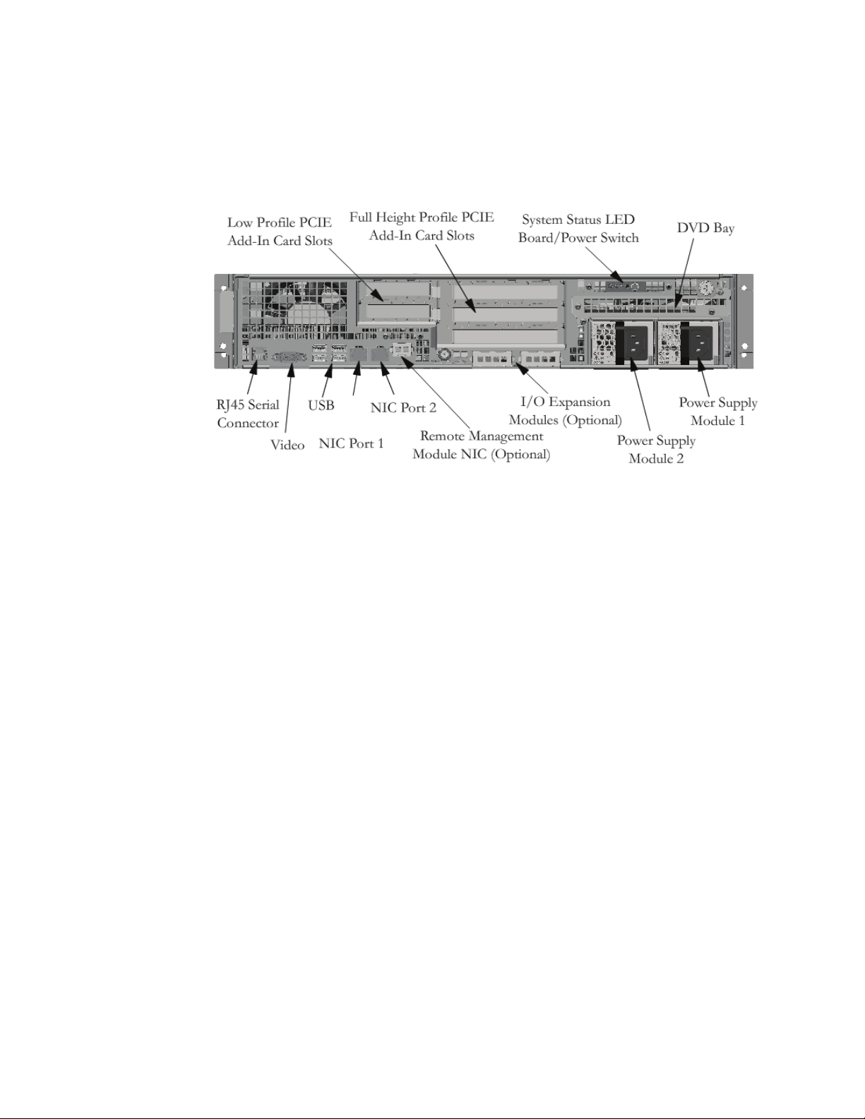
System Rear View
Figure 2. Intel® Server System SR2612UR Rear View
Note: The SAS expansion port is either part of the PCI RAID adapter card or is a separate
multi-port PCI SAS card. Currently, the qualified and supported PCI RAID card are
®
RAID Controller SRCSASJV, Intel® RAID Controller SRCSASLS4I and Intel®
Intel
RAID Controller SASWT4I. Please refer to the Intel Customer Support web site under the
link for these RAID controllers at:http://www.intel.com/support/motherboards/server/
About the Disk Drives and Drive Carriers
The Intel® Server System SR2612UR supports up to 12 SAS and/or SATA disk drives.
SAS and SATA disk drives are not supported within the same appliance enclosure;
however, only in specific configurations (as shown later in this chapter).
Each disk drive is mounted on a drive carrier asse mbly (shown in the following figure)
with a push-button lever for quick installation and removal.
Intel® Server System SR2612UR Service Guide 3
Page 18

Figure 3. Intel® Server System SR2612UR Drive Carrier Assembly
Each drive carrier has three LEDs, which indicate status as described in “Monitoring the
Disk Drives”.
To maintain proper airflow and cooling inside the appliance, all drive slots must have
either a disk drive carrier assembly populated with an actual disk or a special plastic drive
blank installed. Under no circumstances should the appliance be operated with empty
drive slots or with empty drive carrier assemblies as this could cause damage to the LEDs
on the midplane and/or create thermal problems (as well as void the Limited Warranty).
Disk drives are hot-swappable.
Drive Slot Numbers
Figure 4. Intel® Server System SR2612UR Drive Slots
Warning: Disk drives spin at high speed.When removing a Disk Drive Carrier from an enclosure
with power on, unlatch the carrier and allow the drive to completely spin down for
approximately 15-20 seconds befor e sliding the carrier out of the enclosur e. Removing the
Disk Drive Carrier assembly while the drive is spinning could cause injury and may cause
severe damage to the disk drive.
4 Intel® Server System SR2612UR Service Guide
Page 19

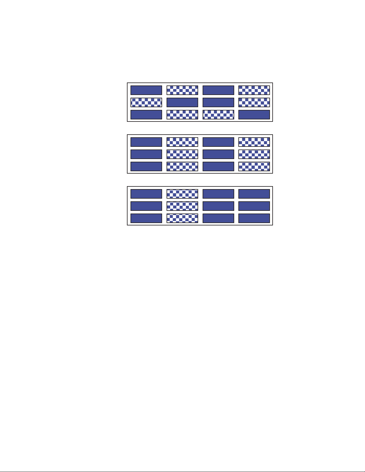
Combining SATA and SAS Disk Drives
If you are combining SAS and SATA disk drives in the same enclosure, use the following
figures to plan where you will place the disk drives.
These figures represent enclosures fully-loaded with disk drives. However, the same
guidelines apply even if you are filling some of the drive slots with blank drive carriers.
Recommended Disk Drive Configurations
Figure 5. Intel® Server System SR2612UR Drive Configurations
Intel® Server System SR2612UR Service Guide 5
Page 20
Unsupported Disk Drive Combinations
Figure 6. Unsupported Disk Drive Combinations
6 Intel® Server System SR2612UR Service Guide
Page 21
Additional Information and Software
If you need more information about these products or information about the accessories
that can be used with these server systems, use the following resources.
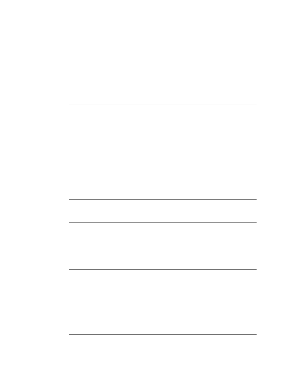
Table 1. Server System References
For this information or
software
For in-depth technical
information about the
server system, including
subsystem overviews and
mechanical drawings
For in-depth technical
information about the
server board, including
board layout, connector
pin-outs, timing
information, mechanical
drawings and LED
information
For basic BIOS settings
and chipset information
If you just received this
product and you need to
assemble your system
and install components
Accessories or other Intel
server products
Use this Document or Software
Intel® Server System SR2612UR Technical Produ ct Specification
Av a ilable at:
http://www.intel.com/support/motherboards/server/sr2612ur/
Intel® Server Board S5520UR Technical Product Specification
Av a ilable at:
http://support.intel.com/support/server boards/server/s5520ur/
®
Intel
Server Board S2612UR Technical Product Specification
Av a ilable at:
http://www.intel.com/support/motherboards/server/sr2612ur/
®
Intel
Server System SR2612UR Quick Start User’s Guide
Provided in the product box
Spares, Parts List and Configuration Guide
Available at:
http://www.intel.com/support/motherboards/server/sr2612ur/
or by using the Server Configurator Tool
Available at:
http://serverconfigurator.intel.com/default.aspx
Hardware (peripheral
boards, adapter cards)
and operating systems
that were tested with this
product
Processors that were
tested with this product
DIMMs that were tested
with this product
Hard Drives that were
tested with this product
Intel® Server System SR2612UR Service Guide 7
Server Configurator Tool
Available at:
http://serverconfigurator.intel.com/default.aspx
Page 22

Table 1. Server System References
For this information or
software
Latest drivers, firmware
updates (BIOS, BMC, and
FRUSDR), and utilities
T o make sure y our system
falls within the allowed
power budget
For software to manage
your Intel
®
server
Use this Document or Software
Available for download at:
http://www.intel.com/support/motherboards/server/sr2612ur/
Click the “Software and Drivers” link on the left side of the web
page.
Power Budget Analysis Tool
Available at:
http://www.intel.com/support/motherboards/server/sr2612ur/
®
System Management Software
Intel
Available at:
http://www.intel.com/go/servermanagement/
8 Intel® Server System SR2612UR Service Guide
Page 23

2 Server System Features
This chapter briefly describes the main features of the Intel® Server System SR2612UR.
This includes illustrations of the products, a list of the server system features, and
diagrams showing the location of important components and connections on the server
systems.
®
Figure 7. Intel
Intel® Server System SR2612UR Service Guide 9
Server System SR2612UR
Page 24

Server System Feature Overview
Table 2 summarizes the features of the server systems.
®
Table 2. Inte l
Feature Description
Server System SR2612UR Feature Summary
Dimensions
• 3.43 inches (87 mm) high
• 17.57 inches (446 mm) wide
• Rack Mounting Surface to Rear I/O Tray Module Handle
– 30.79 inches (781.5 mm) deep
• Front Surface of Disk Drive to Rear I/O Tray Module
– 32.01 inches (812.4 mm) deep
• 67 pounds (30.3 kg) - maximum chassis weight
®
Server Board Intel
Processor Support for one or two Intel
Memory Support for 800/1066/1333 MT/s ECC registered (RDIMM) or
Server Board S5520UR
®
Xeon® Processor 5500 Series with a
4.8 GT/s, 5.86 GT/s, or 6.4 GT/s Intel
Support up to 95-W Thermal Design Power (TDP); processors
having higher TDP are not supported.
This server board does not support previous generations of the
®
Intel
Xeon® processors.
For a complete updated list of supported processors, see
http://www.intel.com/support/motherboars/server/sr2612ur/.
On the Support tab, look for Compatibility and then Supported
Processor List.
unbuffered DIMM (UDIMM) DDR3 memory
®
QPI link interface.
• 12 DIMMs across six memory channels (three channels per
processor)
• Intel
®
5520 chipset I/O Hub
®
82801Jx I/O Controller Hub
Chipset • Intel
10 Intel® Server System SR2612UR Service Guide
Page 25

Table 2. Intel® Server System SR2612UR Feature Summary
Feature Description
Peripheral Interfaces External connections:
• Four USB 2.0 connectors (back)
• RJ-45 serial Port A connector
• Two RJ-45 10/100/1000 Mb Network connections
• DB-15 video connector (front and back)
• Internal connections:
• One USB 2x5 pin header, which supports two USB 2.0 ports
• One low-profile USB 2x5 pin header to support low-profile USB
solid state drives
• One DH-10 serial Port B header
• Six Serial ATA II connectors
• Two I/O module connectors
• One RMM3 connector to support an optional Intel
Management Module 3
• SATA Software RAID 5 Activation Key connector
• One SSI-EEB-compliant front panel header
• One SSI-EEB-compliant 24-pin main power connector
• One SSI-compliant 8-pin CPU power connectors
• One SSI-compliant power supply SMBus connector
®
Remote
Video On -board Server Engines* LLC Pilot II controller with:
• Integrated 2D Video Controller
• 32 MB DDR2 Memory
LAN Two 10/100/1000 ports provided by Intel® 82575 PHYs
Expansion Capabilities The following riser card options are available:
• Three full-height PCI Express* slots (passive)
• Five full-height PCI Express* slots (active)
Hard Drives
• Intel
Server System SR2612UR:
®
• 12 3.5-inch hot-swap SATA / SAS hard drives
• Two optional 2.5-inch fixed 3Gbps SATA hard drives (inside
chassis).
®
• Intel
Embedded Server RAID Techno logy II with SW RAID
levels 0/1/10
• Optional support for SW RAID 5 with activation key
Peripherals
• Slimline bay for slimline SATA optical drive (back)
• PCI riser card bracket
Control Panel
• Standard control panel provides:
– LEDs (front and back)
– Power switch (back)
Intel® Server System SR2612UR Service Guide 11
Page 26

Table 2. Inte l® Server System SR2612UR Feature Summary
Feature Description
LEDs and displays • Power LED
• Standby Power LED ( +3.3V Standby)
• System Status
• System Identification
• Enclosure Subsystem Fault
• Hard Drive Activity
• Hard Drive Status
®
Light-Guided diagnostics:
Intel
– Fan Fault
– DIMM Fault
– CPU Fault
– 5V-Standby
– System Status
– System Identification
• POST Code Diagnostics
Power Supply Up to two 760-W power supply modules
Fans
• Non-redundant fan option containing four system fans
• Non-redundant fan in each power supply module
System Management On-board ServerEngines* LLC Pilot II Controller
• Integrated Baseboard Management Controller (Integrated
BMC), IPMI 2.0 compliant
• §Integrated Super I/O on LPC interface
Support for Intel
Server System Components
This section helps you identify the components of your server system. If you are near the
system, you can also use the Quick Reference Label provided on the inside of the chassis
cover to assist in identifying components.
®
System Management Software 3.1
12 Intel® Server System SR2612UR Service Guide
Page 27

Figure 8. Intel® Server System SR2612UR Configuration Diagram
Intel® Server System SR2612UR Service Guide 13
Page 28
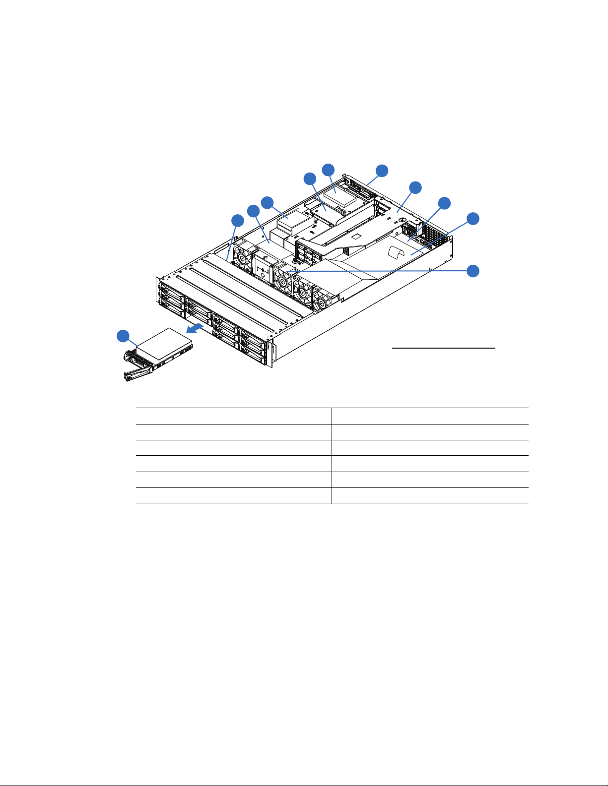
Intel® Server System SR2612UR Components
A - POWER SUPPLY
B - POWER DIST BOARD
C - PCI RISER ASSY
D - SERVER BOARD
E - BACKPLANE PCB
F - HARD DRIVE ASSY
G - SYSTEM AIR DUCT
H - FAN MODULE
I - 2.5” SYSTEM DRIVES
J - RAID CARD BATTERY
K - CD/DVD DRIVE
I
F
A
C
D
E
G
H
B
J
K
OPTIONAL HARDWARE
14 Intel® Server System SR2612UR Service Guide
A. Power Supply G. System Air Duct
B. Power Distribution Board H. Fan Module
C. PCI Riser Assembly I. 2.5-inch System Drives
D. Ser ver Board J. RAID Card Battery (Optional)
E. Backplane PCB K. CD/DVD Drive (Optional)
F. Hard Drive Assembly
Figure 9. Intel® Server System SR2612UR Components
Page 29

Intel® Light-Guided Diagnostics
The server system contains the following diagnostic LEDs, each providing the following
functions:
• The System Power LED on the front and back panels (see Figure 11 and Figure 12)
shows the system power supplies status (off, green).
• The Enclosure Services Subsystem fault LED on the front and back panels (See
Figure 11 and Figure 12) shows health of the enclosure service subsystem (off,
amber).
• The System Status LED on the front and back panels (see Figure 11 and Figure 12)
shows the overall health of the system (green, blinking green, blinking amber,
amber, off).
• The System Identification LED on the front and back panel (see Figure 11 and
Figure 12) helps identify the server from among several servers. The ID LED is off
by default, and blue when activated by button or software.
Intel® Server System SR2612UR Service Guide 15
Page 30
.
A
B
C
D
E
J
F
G
I
J
A. POST Code Diagnostic LEDs B. System Identification LED
C. Status LED D. Memory 1 Fan Fault LED
E. CPU 1 Fan Fault LED F. CPU 1 DIMM Fault LEDs
G. CPU 2 Fan Fault LED H. Memory 2 Fan Fault LED
I. CPU 2 DIMM Fault LEDs J. 5V Standby LED
®
Figure 10. Intel
16 Intel® Server System SR2612UR Service Guide
Light-Guided Diagnostic LEDs - Server Board
H
AF002833
Page 31

Figure 11. Intel® Light-Guided Diagnostic LEDs - Standard Control Panel
Intel® Server System SR2612UR Service Guide 17
Page 32

Item Function Color State Description
A. Standby Power
OK LED (+3.3V)
B. System Status LED Green Solid On System booted and ready
C. System Status LED Amber Blink Non-critical
D. System Identification
LED
E. Power Switch N/A N/A N/A
Green Off AC Power Off
Blue On Identify active through command
Figure 12. System Power LED Back Panel
Server Board Components
This section helps you identify the components and connectors on the server board.
On AC power on or DC power on
Blink Degraded
Solid On Critical, non-recoverable
Off No Identification
18 Intel® Server System SR2612UR Service Guide
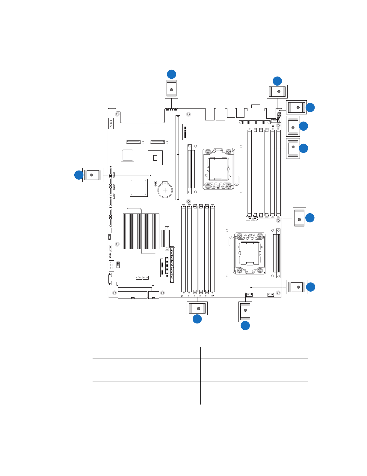
Page 33

AF002696
EBC FGDA
EE
DD
CC
BB
AA
Z
Y
V
W
X
U
T
J
H
I
K
L
MNSROPQ
Intel® Server System SR2612UR Service Guide 19
Page 34

A. 280-pin Intel® Adaptive Slot B. POST Code Diagnostic LEDs C. Intel® RMM3 Header
D. Processor 1 Socket E. Back Panel I/O Ports F. System Identification LED
G. System Status LED H. Memory 1 Fan Header I. CPU 1 Fan Header
J. Processor 1 DIMM slots K. Processor 2 DIMM slots L. Processor 2 Socket
M. CPU 2 Fan Header N. Memory 2 Fan Header O. Bridge Board Connector (Intel
Server Chassis)
P. Front Panel Connector Q. Fan Board Connector R. 2x4 Power Connector
®
S. Main Power Connector T. Power Supply SMBus
Connector
V. USB Header W . Low-profile USB Solid State
Drive Header
Y. LCP IPMB Header Z. SATA RAID 5 Key Header AA. SGPIO Header
BB. SATA Connectors CC. I/O Module Mezzanine
Connector 2
EE. Serial Port B Header
U. System 2 Fan Header
X. System 1 Fan Header
DD. I/O Module Mezzanine
Connector 1
Figure 13. Server Board Connector and Component Locations
20 Intel® Server System SR2612UR Service Guide
Page 35

Configuration Jumpers
AF002832
J1D4
BIOS Recover
2
3
Normal
Recover
J1E8
Password Clear
2
3
Protect
Clear
J1E7
BIOS Default
2
3
Normal
Set
Default
J1H2
BMC Force Update
2
3
Disable
Enable
J9A1
Serial Port
Configuration
34
2
DCD to DTR
DSR to DTR
(factory default)
E
D
C
B
A
Jumper Name Jumper Purpose
A. Serial Port Configuration
(J9A1)
B. BMC Force Update
(J1H2)
If pins 1-2 are jumpered, the DCD to DTR mode is enabled. These
pins should be jumpered on 3-4 to operate in the DSR to DTR
(default) mode.
If pins 2-3 are jumpered, the Integrated BMC Force Update Mode is
enabled. These pins should be jumpered on 1-2 for normal system
operation.
C. BIOS Default (J1E7) If pins 2-3 are jumpered, the BIOS settings are cleared on the next
reset. These pins should be jumpered on 1-2 for normal operation.
D. Password Clear (J1E8) If pins 2-3 are jumpered, administrator and user passwords are
cleared within five to ten seconds after the system is powered on.
These pins should be jumpered on 1-2 for normal system
operation.
Intel® Server System SR2612UR Service Guide 21
Page 36

Jumper Name Jumper Purpose
E. BIOS Recover (J1D4) If pins 2-3 are jumpered, the system can only boot from EFI-
bootable recovery media with the recovery BIOS image. The main
system BIOS will not boot. These pins should be jumpered on 1-2
for normal system operation.
Figure 14. Configuration Jumpers
Front of Intel® Server System SR2612UR
Peripheral Devices
The Intel® Server System SR2612UR provides locations and hardware for installing hard
drives, CD-ROM drive, or DVD-ROM drive. The drives must be purchased separately.
The following figure shows the available options.
22 Intel® Server System SR2612UR Service Guide
Page 37

.
A. Hot-Swap 3.5-inch Hard Drive Bays (12)
B. Internal fixed 2.5-inch SATA Hard Drive Bays (2)
C. Slimline SATA Optical Drive Bay (1)
Hard Disk Drive Carriers
The server system ships with 12 drive carriers for installing 12 SAS or Serial AT A (SATA)
hot-swap drives.
Figure 15. Optional Peripherals
Intel® Server System SR2612UR Service Guide 23
Page 38

Note: Drives can consume up to 17 watts of power each. Drives must be specified to run at a
maximum ambient temperature of 45
®
Note: The Intel
drives. For a web link to a list of supported hard drives, see “Additional Information and
Software” on page -7.
Server System SR2612UR does not support all SAS or Serial AT A (SATA) hard
Slimline Optical Drive Carrier
The slimline optical drive carrier can be used with a single slimline optical drive. One
slimline carrier is included with your server system; the optical drive must be purchased
separately.
The drive inside the chassis is NOT hot-swappable. The system power must be turned off
to insert or remove the slimline optical drive carrier.
To use one of the drives provided by Intel, use the following order codes:
• Slimline DVD-ROM Drive: AXXSATADVDROM
• Slimline DVD-RW Drive: AXXSATADVDRWROM
®
Note: The Intel
web link to a list of supported slimline optical drives, see “Additional Information and
Software” on page -7. Intel provides accessory kits for these drives.
Server System SR2612UR does not support all slimline optical drives. For a
°C.
Control Panel
The Intel® Server System SR2612UR only has one control panel option..
Figure 16. Rear Control Panel
24 Intel® Server System SR2612UR Service Guide
Page 39

Item Function Color State Description
A. Stan dby Power
OK LED (+3.3V)
B. System Status LED Green Solid On System booted and ready
C. System Status LED Amber Blink Non-critical
D. System Identification
LED
E. Power Switch N/A N/A N/A
Green Off AC Power Off
On AC power on or DC power on
Blink Degraded
Solid On Critical, non-recoverable
Blue On Identify active through command
Off No Identification
Intel® Server System SR2612UR Service Guide 25
Page 40

SAS/SATA Midplanes
The midplane serves as the primary interface between the server board, hot-swap
backplane, and control panel. Only one midplane is offered for this system:
• Active SAS midplane
Note: SATA connectors 6 and 7 are not used in the Intel
Active Midplane
The following diagram show the location for each connector found on the active
midplane.
®
Server System SR2612UR.
A. SAS Connector B. Backplane Connector
Figure 17. Active SAS Midplane Components
26 Intel® Server System SR2612UR Service Guide
Page 41

Hot-Swap SAS/SATA Backplane
The backplane serves as an interface between the midplane board and the system drives.
The hot-swap backplane provides support for both SAS and SATA hard drives. There are
no hard drive cables that connect to the backplane. All hard drive control signals are
routed from the midplane board, which plugs directly into the backplane.
A. SAS/SATA Hard Disk Drive Connectors
Figure 18. 3.5-inch Hot-Swap SAS/SATA Backplane Components (Front View)
A. Backplane Power Connector C. Midplane Board Connector
B. Server Board/Midplane GPIO Connector
Figure 19. 3.5-inch Hot-Swap SAS/SATA Backplane Components (Rear View)
Intel® Server System SR2612UR Service Guide 27
Page 42

RAID Support
For RAID support on the active midplane, you should install an additional RAID
controller.
For information on configuring RAID, see the Intel
included on the Intel
®
Server Deployment Toolkit 3.0 CD.
Advanced Management Options
Intel® Remote Management Module 3
The Intel® Remote Management Module 3 plugs into a dedicated connector on the server
board and provides additional server management functionality to the server board.
This module provides a dedicated web server for viewing server information and remote
control of the system. It also provides Remote KVM Redirection and USB Media
Redirection allowing USB devices attached to the remote system to be used on the
managed server.
®
RAID Software User’s Guide that is
Rack Mount Options
Your Intel® Server System SR2612UR can be mounted into a rack. Intel provides the
following option to mount this server system into a rack:
• A basic slide rail kit designed to mount the system into a standard (19 inches by up
to 34 inches deep) EIA-310D compatible server cabinet.
When installing the system into a rack, Intel recommends you install systems from the
bottom of the rack to the top. In other words, install the first system in the rack into the
bottom position of the rack, the second system in the second position from the bottom, and
so on. For instructions on installing your chassis into a rack, see “Installing Your Intel
Server System SR2612UR into a Rack (Optional)” on page -30. These instructions are
also included in the rail kit.
®
28 Intel® Server System SR2612UR Service Guide
Page 43

3 Hardware Installations and
Upgrades
Before You Begin
Before working with your server product, pay close attention to the “Safety Information”
on page v at the beginning of this manual.
Note: Whenever you service the system, you must first power down the server and unplug all
peripheral devices and the AC power cord.
Tools and Supplies Needed
• Phillips* (cross head) screwdrivers (#1 bit and #2 bit)
• Needle nosed pliers
• Anti-static wrist strap and conductive foam pad (recommended)
System References
All references to left, right, front, top, and bottom assume the reader is facing the front of
the server system as it would be positioned for normal operation.
Preparing for Installation
1. Carefully read “Safety Information” on page v at the beginning of this manual.
2. Remove all the components from the packaging, inspect them for shipping damage,
then place them on an antistatic surface until you are ready to use them.
If you are using new disk drives, allow them to acclimate to room temperature
before installing them.
3. If you are installing the appliance in a rack, ensure that you have these tools
available:
— Phillips screwdriver
— Bubble level
— Arrange for someone to assist you during installation.
— Ensure ahead of time that you have chosen a suitable location for the appliance
and the rack. (See “Safety Information” on page v at the beginning of this
manual.)
Intel® Server System SR2612UR Service Guide 29
Page 44

Installing Your Intel® Server System SR2612UR into a Rack (Optional)
If you are not installing your appliance into a rack, skip the remainder of this section and
go to “Installing the Disk Drives” on page 33.
To install your appliance into a rack:
1. Ensure you have these rail kit components:
— One right rail assembly
— One left rail assembly
— Ten 10-32 cage nuts (square hole cabinets)
— Ten 10-32 speed nuts (round hole cabinets)
— Ten 10-32 x 0.50 Phillips pan head screws
2. Ensure the four screws contained within the slider mechanism are loosened.
Figure 20. Slider Mechanism
3. Slide the front and rear portions of the rail away from each other until the length is
correct for your cabinet. Secure the front and rear portions of the rail kit to the front
and rear supports as shown in the following figure. Ensure all connections are
tightened and secure.
30 Intel® Server System SR2612UR Service Guide
Page 45

Figure 21. Securing the Front and Rear Portions of the Rail Kit
4. Tighten the four screws on each rail's slider mechanism.
Figure 22. Tightening the Screws on the Rail’s Slider Mechanism
Caution: A fully loaded appliance is heavy . To avoid personal injury, have someone help you lift the
appliance.
Intel® Server System SR2612UR Service Guide 31
Page 46

5. Slide the appliance onto the rails, then push it all the way back until the rackmount
ears are flush against the vertical supports and the appliance rests completely on the
rails.
Figure 23. Sliding the Appliance onto the Rails
6. Secure both rackmount ears to the vertical supports using two of the 10-32 x .50-
inch screws and carefully snap the plastic rack ear covers in place as shown. The
rack installation is complete.
32 Intel® Server System SR2612UR Service Guide
Page 47

Installing the Disk Drives
Caution: Before installing new disk drives, acclimate them to room temperature. Store drives at
room temperature for two hours prior to use.
Note: To insta ll a disk drive or plastic blank into a carrier, refer to “Drive Installation in the
Drive Carrier” on page 75 in this manual.
1. Select an open drive slot.
2. Hold the disk drive so the LEDs are on the left and the lever is fully open.
3. Slide the disk drive into the drive slot until the lever starts to close.
Figure 24. Sliding the Disk Drive into the Drive Slot
4. Push the lever until it meets the latch on the left side of the drive slot and clicks into
place.
Intel® Server System SR2612UR Service Guide 33
Page 48

Figure 25. Pushing the Lever Until It Meets the Latch on Left Side of the Drive Slot
5. Repeat for all remaining disk drives. Drive installation is easier when installing
drives from right to left in the enclosure.
Note: To maintain proper airflow and cooling, you must install a disk drive carrier populated
with an actual disk drive or plastic drive blank assembly in every slot of the enclosure.
Under no circumstances should the appliance be operated with empty drive slots or with
empty drive carrier assemblies as this could cause damage to the LEDs on the backplane
and/or create thermal problems.
34 Intel® Server System SR2612UR Service Guide
Page 49

Removing a Disk Drive Carrier Assembly (or Drive Blank)
Note: For disk drive installation instructions, see “Installing the Disk Drives” on page 33.
Important Safety Precautions
Before you remove a populated disk drive carrier, read these important notes:
• To avoid data loss, stop all I/O activity on the disk drive before removing it.
(Removing a disk drive during I/O activity could also hang the host system.)
• Do not attempt to remove more than one disk drive or blank drive carrier at a time.
Damage to the drive carrier can occur if adjacent disk drives are removed at the
same time.
• To maintain proper airflow and cooling inside the enclosure, install either a
populated disk drive carrier or a plastic drive blank assembly into the empty drive
slot as quickly as possible.
If you will be installing a replacement drive carrier populated with a new disk drive, allow
it to acclimate to room temperature before continuing.
Removing a Disk Drive
Warning: Disk drives spin at high speed.When removing a Disk Drive Carrier from an enclosure
with power on, unlatch the carrier and allow the drive to completely spin down for
approximately 15-20 seconds before sliding the carrier out of the enclosure. Removing the
Disk Drive Carrier assembly while the drive is spinning could cause injury and may cause
severe damage to the disk drive.
To remove a populated disk drive carrier assembly (or drive blank assembly):
1. Press the button on the assembly to release the lever.
Intel® Server System SR2612UR Service Guide 35
Page 50

Figure 26. Pushing the Button on the Assembly
2. Gently pull open the lever.
The drive carrier or drive blank unlocks.
Figure 27. Drive Carrier Unlocked
3. If the enclosure is powered on, allow the disk drive to fully spin down (wait
approximately 15-20 seconds).
Warning: Removing a populated disk drive carrier before it has fully spun down may result in disk
drive damage and possible personal injury.
4. Gently pull the disk drive carrier or drive blank out of the enclosure.
5. Immediately replace the disk drive carrier assembly or install a drive blank
assembly to maintain correct airflow and cooling. For more information on
installing disk drives, see “Installing the Disk Drives” on page 33.
36 Intel® Server System SR2612UR Service Guide
Page 51

Installing the Operating System
The Intel® Server System SR2612UR is now ready to have the operating system installed.
Please contact your IT representative to perform this installation or if you are installing it
yourself, please follow the general guidelines below.
1. Connect the power cords to the rear of the unit.
2. Connect a monitor, keyboard, and mouse to the rear connections on the enclosure.
3. Turn on power to the enclosure by pressing the power button on the rear of the
enclosure.
4. Insert the operating system CD/DVD.
5. Follow the instructions for installing the operating system.
6. If you want to install additional drivers or programs (for the PCI cards or other
devices), you should also install them at this time.
The system is now ready to boot up. Booting the system may take several minutes.
Intel® Server System SR2612UR Service Guide 37
Page 52

Connecting Your Intel® Server System SR2612UR to a Host Server
Connecting to the 1GE iSCSI LAN Data Ports
Consult your operating system/software user guide for details on assigning LAN IP
addresses to the integrated system 1GE iSCSI data ports.
For iSCSI applications running on the Intel
connectivity is required. The following figure illustrates a direct iSCSI connection
between the host system and one of the two Ethernet ports on the Intel
SR2612UR. An Ethernet switch and/or optional internal 1GE or 10GE iSCSI PCI card
may also be used to make these connections.
®
Server System SR2612UR, Ethernet
®
Server System
Figure 28. Establishing a Connection to the LAN Data Port
If you are not connecting additional enclosures, continue with “Powering On” on page 38.
Connecting Additional Enclosures
You can expand your configuration with storage enclosures depending on the number of
drives supported by the SAS or SATA HBA.
You can inc l ude enclosures installed with SAS disk drives and enclosures installed with
SATA disk drives in the same daisy-chain. Refer to the SAS or SATA HBA User Guide
for a list of supported expansion enclosures.
Connect a SAS cable to the expansion port on the rear of the enclosure. Connect the other
end to the controller SAS port on the rear of the expansion enclosure.
Powering On
1. Using the included power cords, connect each Power Supply (PS) unit to an AC
power source. (It is recommended that you use an uninterruptible power supply to
protect your appliance.)
38 Intel® Server System SR2612UR Service Guide
Page 53

Note: The dual 2.5-m power cords included with the Intel® Server System SR2612UR have
domestic North American NEMA 5-15 plugs. If required, you can obtain International
power cords locally (for example, via the Internet at http://www.interpowers.com).
Figure 29. Powering-On
2. Press the Master Power Switch to power on the unit.
®
Note: Note: On power up the internal server board on the Intel
take a couple of minutes to complete initialization and operating system boot activities.
The installation is complete. You can begin using your Intel
Server System SR2612UR may
®
Server System SR2612UR.
Installing a 2.5-inch Internal Drive
The Intel® Server System SR2612UR supports up to two (2) internal 2.5-inch SATA
drives. They are connected directly to the CPU server board and provide the capability to
run the operating system from these drives.
Complete the following steps to install one or more 2.5-inch internal drives in the Intel
Server System SR2612UR. For a list of supported drives, contact your Intel sales
representative.
1. Ensure the AC power cord(s) are disconnected from the enclosure.
2. Remove the top cover from the enclosure by loosening the captive screw with a
Phillips screwdriver on the right-rear of the enclosure.
3. Slide the top cover back and lift it from the enclosure.
4. Locate the 2.5-inch drive sled as shown.
®
Intel® Server System SR2612UR Service Guide 39
Page 54

5. Remove the drive sled by loosening the captive thumbscrew.
Figure 30. Removing the drive sled
6. Position the drive(s) as shown and secure using the 4 screws provided with the
drive. If installing only one drive, locate the drive on the bottom shelf of the sled.
Figure 31. Installing the boot drives
7. Reinstall the drive sled and tighten down the captive thumbscrew.
8. The power cables for the 2.5-inch drives are located near the drive sled. Attach the
cable(s) to the drive(s).
9. Carefully remove the CPU server board air duct.
40 Intel® Server System SR2612UR Service Guide
Page 55

10. Using the SA TA cable supplied with the drive, route the cable from each disk drive
to the CPU server board SATA connectors.
Figure 32. Connections Diagram
11. Carefully reinstall the CPU server board air duct.
12. Reinstall the top cover and tighten the captive screw.
13. Reinstall the power cord(s).
DVD Installation
The Intel® Server System SR2612UR supports an optional DVD. Complete the following
steps to install a DVD drive in the Intel® Server System SR2612UR.
1. Ensure the AC power cord(s) are disconnected from the enclosure.
2. Remove the top cover from the enclosure by loosening the captive screw with a
Phillips screwdriver on the right rear of the enclosure.
3. Slide the top cover back and lift it from the enclosure.
4. On the rear of the enclosure, locate the removable DVD cover plate.
5. Remove the four screws and cover plate using a Phillips* screwdriver shown in the
following figure.
Intel® Server System SR2612UR Service Guide 41
Page 56

Figure 33. Removing the four screws and cover plate
6. Looking into the top of the enclosure, locate the DVD tray screw and remove. This
screw will be re-used.
Figure 34. Removing the four screws and cover plate
7. Slide the DVD tray out of the enclosure.
8. Position the DVD unit as shown in the following figure and carefully snap the unit
in place by aligning the pointed tabs with the screw holes on the DVD unit.
42 Intel® Server System SR2612UR Service Guide
Page 57

Figure 35. Position the DVD Unit
9. Slide the DVD / tray assembly back into the enclosure and anchor it using the screw
that was removed in Step 7.
10. Using the slimline cable shipped with the system, connect the power end of
slimline cable to the power cable located in the enclosure and the SATA end of
slimline cable to the CPU server board. If 2.5-inch drives are installed, connect the
SATA cable to the SATA2 connector.
Figure 36. Routing the Cable From the DVD Unit to the Server Board
11. Reinstall the top cover and tighten the captive screw.
12. Reinstall the power cord(s).
Replacing a Fan
You should replace a defective fan as soon as possible to maintain proper cooling in the
enclosure. Complete the following steps to remove and install a fan in the Intel
System SR2612UR.
Intel® Server System SR2612UR Service Guide 43
®
Server
Page 58

1. Ensure the AC power cord(s) are disconnected from the enclosure.
2. Remove the top cover from the enclosure by loosening the captive screw with a
phillips screwdriver on the right-rear of the enclosure.
3. Slide the top cover back and lift it from the enclosure.
4. If the defective fan is located on the server board side of the enclosure, carefully
remove the system air duct to allow access to the fan (reference item G on the
System component diagram).
5. Remove the defective fan by pushing the top of the fan towards the rear of the
enclosure until the fan pops free.
6. Carefully disconnect the 4-wire connector from the PCB (note the wire routing) and
remove the defective fan from the enclosure.
Installing a Fan
Installing a fan is the opposite of “Replacing a Fan” on page 43.
1. Carefully connect the 4-wire connector onto the pc board. Route the wires so that
they will not interfere with other components and snap the fan back into place by
aligning the mounting holes with the spring clip dimples. Press the fan downward
until it snaps into place.
2. Carefully replace the system air duct if it was removed in Step 4.
3. Reinstall the top cover and tighten the captive screw.
4. Reinstall the power cord(s).
Figure 37. Removing the Defective Fan
44 Intel® Server System SR2612UR Service Guide
Page 59

Midplane Board Replacement
Complete the following steps to remove and install an midplane in the Intel® Server
System SR2612UR.
1. Ensure the AC power cord(s) are disconnected from the enclosure.
2. Remove the top cover from the enclosure by loosening the captive screw with a
Phillips screwdriver on the right-rear of the enclosure.
3. Slide the top cover back and lift it from the enclosure.
4. Locate the midplane (located between the backplane and fans).
Figure 38. Midplane
5. Disconnect the I/O cable by depressing the release tab and pulling the cable
upward.
Caution: You must depress the I/O SAS cable release tab when removing the cable to prevent I/O
connector damage.
6. Remove the two screws holding the midplane in place.
Intel® Server System SR2612UR Service Guide 45
Page 60

7. Carefully disconnect the midplane from the backplane as shown in the following
figure.
Figure 39. Disconnecting the Midplane from the Backplane
8. Carefully connect the new midplane to the backplane.
9. Reinstall the two screws to hold the midplane in place. Be careful not to overtighten
the screws.
10. Reconnect the I/O SAS cable by gently inserting into the metal socket. Ensure the
cable was reinstalled correctly.
11. Reinstall the top cover and tighten the captive screw.
12. Reinstall the power cord(s).
Memory Installation
The server board supports up to 12 DDR3 DIMMs, six per processor. The maximum
memory capacity is 96 GB.
Note: The memory slots associated with a particular processor are unavailable if the given
processor socket is not populated with a CPU chip.
Memory recommendations:
1. It is recommended that the same type, size, and manufacturer of DIMM module be
used throughout the enclosure. Using different memory vendors in the same
enclosure may cause unexpected results when booting and running the machine.
2. It is recommended that the same overall size of memory is used for both processors.
For a list of supported memory vendors and capacities, contact your Intel sales
representative.
Mixed speed DIMMs are accommodated by using the highest common frequency
of all memory modules installed.
46 Intel® Server System SR2612UR Service Guide
Page 61

To replace or add memory to the Intel® Server System SR2612UR, complete the
following steps.
1. Ensure that the AC power cord(s) are disconnected from the enclosure.
2. Remove the top cover from the enclosure by loosening the captive screw with a
Phillips screwdriver on the right-rear of the enclosure.
3. Slide the top cover back and lift it from the enclosure.
4. Carefully remove the system air duct over the CPU server board.
5. Referencing the following Serve r Board Configuration Diagram, memory DIMMs
must be installed / filled in the following order:
— Slot A1, Slot B1, Slot C1 (CPU 1)
— Slot D1, Slot E1, Slot F1 (CPU 2)
Once the above slots are full, then:
— Slot A2, Slot B2, Slot C2 (CPU1)
— Slot D2, Slot E2, Slot F2 (CPU2)
Figure 40. Memory Slots on the Server Board
Note: You can populate memory in any order only if the CPU server board is running in
Channel Independent Mode. Please reference the CPU server board functional
specification if the enclosure will be running in Channel Independent Mode. Also refer to
the specification if the server board will be r unning in either Ch annel Sparing or Chan nel
Mirroring Mode as there are specific memory installation configurations required.
6. To install the DIMM, open the release levers on each side of the memory socket and
press down on the DIMM until the release levers snap closed.
Intel® Server System SR2612UR Service Guide 47
Page 62

Note: The DIMMs are “keyed” so they can only be inserted one way in the socket.
Figure 41. Installing a DIMM
7. Once the DIMMs are installed, carefully replace the system air duct over the server
board.
8. Reinstall the top cover and tighten the captive screw.
9. Reinstall the power cord(s).
PCI Card and Battery Installation
The Intel® Server System SR2612UR supports to five PCI-E option cards. A typical
configuration uses a PCI-E-based RAID card to communicate with the 12 drive slots.
Complete the following steps to install a PCI-E card in the Intel
SR2612UR.
1. Ensure the AC power cord(s) are disconnected from the enclosure.
2. Remove the top cover from the enclosure by loosening the captive screw with a
Phillips screwdriver on the right rear of the enclosure.
3. Slide the top cover back and lift it from the enclosure.
4. Locate the PCI cage assembly and loosen the two (2) captive thumbscrews.
5. As shown in the following figure, carefully lift the entire PCI cage assembly out of
the enclosure.
®
Server System
48 Intel® Server System SR2612UR Service Guide
Page 63

Figure 42. Lifting the PCI Cage Assembly Out of the Enclosure
6. Remove the metal blank filler for the appropriate slot you will be plugging the card
into (the top slot is used for the first installed card).
7. Carefully install the PCI card starting at the top slot of the PCI cage. PCI cards are
keyed so they cannot be installed backwards.
8. To reinstall the PCI cage assembly, line up the tabs at the bulkhead cutouts on the
rear of the enclosure.
9. Carefully lower the assembly and align the PCI cage circuit card with the CPU
server board connector. Press into place.
10. Tighten the two (2) captive screws on the PCI card cage assembly.
11. Depending on the type of card installed, there may be cables that have to be routed.
In the case of a RAID card, you must route the SAS cable through the fan assembly
(where other cables are routed) and connect to the I/O module located just behind
the midplane.
Intel® Server System SR2612UR Service Guide 49
Page 64

Figure 43. Routing the Cables Through the Fan Assembly
A - POWER SUPPLY
B - POWER DIST BOARD
C - PCI RISER ASSY
D - SERVER BOARD
E - BACKPLANE PCB
F - HARD DRIVE ASSY
G - SYSTEM AIR DUCT
H - FAN MODULE
I - 2.5” SYSTEM DRIVES
J - RAID CARD BATTERY
K - CD/DVD DRIVE
I
F
A
C
D
E
G
H
B
J
K
OPTIONAL HARDWARE
12. If there is an external battery associated with the PCI card, it must be mounted with
the supplied mounting screws in the location indicated in the following figure
50 Intel® Server System SR2612UR Service Guide
Figure 44. Mounting an External Battery
13. Reinstall the top cover and tighten the captive screw.
Page 65

14. Reinstall the power cord(s).
Power Supply Replacement
Complete the following steps to remove and install a power supply in the Intel® Server
System SR2612UR.
1. Ensure the AC power cord(s) are disconnected from the enclosure.
2. Remove the top cover from the enclosure by loosening the captive screw on the
right-rear of the enclosure with a Phillips screwdriver.
3. Slide the top cover back and lift it from the enclosure.
4. Remove the power supply by pushing in and holding the green latch in the
directions shown in the following figure.
Figure 45. Removing the Power Supply
5. Using the handle, carefully slide the power supply out of the enclosure chassis.
6. Reinstall a new power supply by inserting it into the chassis enclosure until it clicks
into place.
7. Reinstall the top cover and tighten the captive screw.
8. Reinstall the power cord(s).
Replacing the Backplane Board
The following sections describe how to replace the backplane board.
Intel® Server System SR2612UR Service Guide 51
Page 66

Removing the Backplane Board
Observe ESD precautions when servicing this unit. At a minimum, use an ESD grounded
wrist strap when handling electrical components. Where possible utilize a grounded ESD
mat to place drives and components on. For more information, refer to “Safety
Information” on page 123.
1. Power down the enclosure and remove the power cord(s).
2. Remove all disk drives. Note their slot location in the enclosure.
3. Remove the top cover from the enclosure by loosening the captive screw with a
Phillips screwdriver on the right-rear of the enclosure.
4. Slide the top cover back and lift it from the enclosure.
5. Remove the main power connector from the backplane as shown in Figure 46.
Figure 46. Removing the Main Power Connector from the Backplane
6. Remove the logic cable connector from the backplane as shown in Figure 47
Figure 47. Removing the Logic Cable Connector from the Backplane
7. Remove the midplane from the enclosure as detailed in the User Guide appendix.
(Remove the I/O SAS cable and the two (2) screws holding the midplane in place,
then carefully disconnect the midplane from the backplane.)
52 Intel® Server System SR2612UR Service Guide
Page 67

Figure 48. Removing the Midplane from the Enclosure
8. Using an extended Phillips head screwdriver reach in from the front of the
enclosure and remove the seven (7) screws attaching the backplane
Figure 49. Removing the Screws that Attach the Backplane
9. Carefully pull back on the top of the backplane and lift it out of the enclosure
Figure 50. Pulling Back the Backplane and Lifting It Out of the Enclosure
Intel® Server System SR2612UR Service Guide 53
Page 68

Installing and Removing the RAID Battery Backup Unit
Installing the RAID Battery Backup Unit (BBU)
Warning: Observe ESD precautions when servicing this unit. At a minimum utilize an ESD
grounded wrist strap when handling electrical components. Where possible utilize a
grounded ESD mat to place drives and components on.
To install the RAID battery backup unit, follow these steps:
1. Power down the enclosure and remove the power cord(s).
2. Remove all disk drives. Note their slot location in the enclosure.
3. Remove the top cover from the enclosure by loosening the captive screw with a
Phillips screwdriver on the right-rear of the enclosure.
4. Slide the top cover back and lift it from the enclosure.
5. Locate the battery mounting plate in the enclosure as shown below
Figure 51. Locate the battery
54 Intel® Server System SR2612UR Service Guide
Page 69

6. Remove the standoff from the battery plate as shown below.
Figure 52. Remove the standoff
7. Align the battery pack as shown (with cable installed), and put into place by
inserting the plastic tabs into the slots and sliding the pack in the direction of the
arrow on the battery plate until the unit snaps into place.
Figure 53. Align the battery pack
Intel® Server System SR2612UR Service Guide 55
Page 70

Figure 54. Aligning the battery pack
8. Replace and tighten the standoff that was removed in step 6
Figure 55. Replace and tighten standoff
9. Route the cable from the battery pack as shown below.
Figure 56. Route the cable
56 Intel® Server System SR2612UR Service Guide
Page 71

10. Connect the cable to the installed PCI RAID board as shown below
Figure 57. Connect the cable to PCI RAID Card
11. Reinstall the top cover and tighten the captive screw.
12. Reinstall the power cords.
Installing and Removing the Server Board
Removing the Server Board
To remove the server board, follow these steps:
1. Power down the enclosure and remove the power cord(s).
2. Remove the top cover from the enclosure by loosening the captive screw with a
Phillips screwdriver on the right-rear of the enclosure.
3. Slide the top cover back and lift it from the enclosure.
4. Remove the processor air duct.
5. Remove the PCI riser assembly.
6. Remove the Intel
7. Disconnect power cables, P1, P2, P3 and Front Panel logic cable, fro m
Motherboard as shown below.
®
RMM3, if installed.
Intel® Server System SR2612UR Service Guide 57
Page 72

Figure 58. Disconnect the power cables
8. Disconnect fan cables, FAN 1, FAN 2, FAN 3 and FAN 4 from Motherboard as
shown below
Figure 59. Disconnect the fan cables
9. Remove memory.
10. Remove the processor heatsink(s) and processor(s).
11. Remove the nine screws from the server board and lift the server board from the
server system as shown below.
58 Intel® Server System SR2612UR Service Guide
Page 73

Figure 60. Remove the screws
12. Install the replacement server board.
Intel® Server System SR2612UR Service Guide 59
Page 74

Installing the Server Board
To install the server board, follow these steps:
1. Install Motherboard into chassis by tilting the board and inserting the connectors
into the proper openings on the rear bulkhead as shown below. When the
connectors are placed into the proper openings, slowly place the board into the
chassis without causing any damage to the bottom side components.
Figure 61. Installing the server board
2. Attach the server board with nine screws.
Figure 62. Attach the screws
60 Intel® Server System SR2612UR Service Guide
Page 75

3. Install power cables, P1, P2, P3 and Front Panel logic cable, into Motherboard as
shown below.
Figure 63. Installing power cables
4. Install fan cables, FAN 1, FAN 2, FAN 3 and FAN 4 into Motherboard as shown
below.
Figure 64. Install the fan cables
5. Install memory.
6. Install the processor(s).
7. Install processor heatsink(s).
8. If necessary, install the Intel
®
RMM3.
9. Install the PCI riser assembly.
10. Install the processor air duct.
11. Install the top cover and tighten the captive screw.
12. Install the power cords.
Intel® Server System SR2612UR Service Guide 61
Page 76

Replacing the Backup Battery
The lithium battery on the server board powers the RTC for up to 10 years in the absence
of power. When the battery start s to weaken, it loses voltage, and the server settings stored
in CMOS RAM in the RTC (for example, the date and time) may be wrong . Contact your
customer service representative or dealer for a list of approved devices.
Warning: Danger of explosion if battery is incorrectly replaced. Replace only with the same or
equivalent type recommended by the equipment manufacturer. Discard used batteries
according to manufacturer's instructions.
Advarsel: Lithiumbatteri - Eksplosionsfare ved fejlagtig håndtering. Udskiftning må kun ske med
batteri af samme fabrikat og type. Levér det brugte batteri tilbage til leverandøren.
Advarsel: Lithiumbatteri - Eksplosjonsfare. Ved utskifting benyttes kun batteri som anbefalt av
apparatfabrikanten. Brukt batteri returneres apparatleverandøren.
Varning: Explosionsfara vid felaktigt batteribyte. Använd samma batterityp eller en ekvivalent typ
som rekommenderas av apparattillverkaren. Kassera använt batteri enligt fabrikantens
instruktion.
Varoitus: Paristo voi räjähtää, jos se on virheellisesti asennettu. Vaihda paristo ainoastaan
laitevalmistajan suosittelemaan tyyppiin. Hävitä käytetty paristo valmistajan ohjeiden
mukaisesti.
To replace the backup battery, follow these steps:
1. If installed, remove the PCI riser assembly.
2. If installed, remove the processor air duct.
3. Locate the battery on the server board.
4. Insert the tip of a small flat bladed screwdriver, or an equivalent, under the tab in
the plastic retainer. Gently push down on the screwdriver to lift the battery.
5. Remove the battery from its socket.
6. Dispose of the battery according to local ordinance.
7. Remove the new lithium battery from its package, and, being careful to observe the
correct polarity , insert it in the battery socket.
Note: You will need to run the BIOS Setup to restore the configuration settings to the RTC.
62 Intel® Server System SR2612UR Service Guide
Page 77

Removing and Installing the Power Distribution Module
Removing the Power Distribution Module
To remove the server board, follow these steps:
1. Power down the enclosure and remove the power cord(s).
2. Remove the top cover from the enclosure by loosening the captive screw with a
Phillips screwdriver on the right-rear of the enclosure.
3. Slide the top cover back and lift it from the enclosure.
4. Remove the processor air duct.
5. Remove the PCI riser assembly.
6. Disconnect power cables, P1, P2, P3 and Front Panel logic cable, fro m
Motherboard as shown below.
Figure 65. Disconnect the power cables
Intel® Server System SR2612UR Service Guide 63
Page 78

7. Remove 2 screws from nylon clamps and disconnect power cable “P4” from
backplane as shown below.
Figure 66. Remove the screws
8. Remove cable chase insert foam from cable chase fan blank and then remove power
cable p4 from cable chase fan blank as shown below.
Figure 67. Remove cable chase
64 Intel® Server System SR2612UR Service Guide
Page 79

9. Remove the four screws from the power distribution module and lift the power
distribution module from the server system as shown below.
Figure 68. Remove the four screws from the PDB
10. Install the replacement power distribution module.
Installing Power Distribution Module
1. Install power distribution module onto spacers and Install all four screws as shown
below.
Figure 69. Installing the Power Distribution Module
2. Route cable marked “P4” through the cable chase fan blank as shown below.
Intel® Server System SR2612UR Service Guide 65
Page 80

Figure 70. Route cable P4
3. Install 2 nylon clamps onto cable “P4”, flat side up as shown below.
Figure 71. Install the nylon clamps
4. Connect power cable “P4” into backplane and Install 2 screws into nylon clamps
and secure to chassis as shown below.
66 Intel® Server System SR2612UR Service Guide
Page 81

Figure 72. Connecting cable P4 to backplane
5. Insert cable chase insert foam into cable chase fan blank. See picture below for
foam orientation.
Figure 73. Foam orientation
Intel® Server System SR2612UR Service Guide 67
Page 82

6. Install power cables, P1, P2, P3 and Front Panel logic cable, into Motherboard as
shown below.
Figure 74. Install the power cables
7. Install the PCI riser assembly.
8. Install the processor air duct.
9. Install the top cover and tighten the captive screw.
10. Install the power cords.
68 Intel® Server System SR2612UR Service Guide
Page 83

4 Server Utilities
Using the BIOS Setup Utility
This section describes the BIOS Setup utility options, which is used to change server
configuration defaults. You can run the BIOS Setup with or without an operating system
being present. For information about specific BIOS setup screens, see the Intel
Board S5520UR Technical Product Specification. For a web link to this document, see
“Additional Information and Software” on page 7.
Entering BIOS Setup
T o enter the BIOS Setup, press the F2 function key when prompted during boot time. You
must ensure that all the jumpers are in the normal operating position.
The following prompt appears during the Power-On Self Test (POST) after POST
completes the memory test:
Press <F2> to enter SETUP
®
Server
When the BIOS setup is entered, the Main screen is displayed.
If You Cannot Access Setup
If you are not able to access the BIOS Setup, you might need to restore the BIOS default
settings. For instructions, see “Restoring the BIOS Defaults” on page 74.
Setup Menus
Each BIOS Setup menu page contains a number of features. Except for those features that
are provided only to display automatically configured information, each feature is
associated with a value field that contains user-selectable parameters. These parameters
can be changed if the user has adequate security rights. If a value cannot be changed for
any reason, the feature's value field is inaccessible.
The following table describes the keyboard commands you can use in the BIOS Setup
menus.
Key to Press Description
<F1> Pressing <F1> on any menu invokes the general help window.
Table 3. Setup Menu Key Use
Intel® Server System SR2612UR Service Guide 69
Page 84

Table 3. Setup Menu Key Use
Key to Press Description
Left and right arrows Select Menu - The left and right arrow keys are used to move between
the major menu pages. The keys have no affect if a submenu or pick list
is displayed.
Up arrow Select Item up - The up arrow is used to select the previous value in a
menu item's option list, or a value field’s pick list. Pressing the <Enter>
key activates the selected item.
Down arrow Select Item down - The down arrow is used to select the next value in a
menu item's option list, or a value field’s pick list. Pressing the <Enter>
key activates the selected item.
<F5> or <-> Change Value - The minus key or the <F5> function key is used to
change the value of the current item to the previous value. This key
scrolls through the values in the associated pick list without displaying
the full list.
<F6> or <+> Change V alue - The plus key or the <F6> function key is used to change
<Enter> Execute Command - The <Enter> key is used to activate submenus
<Esc> Exit - The <Esc> key provides a mechanism for backing out of any field.
<F9> Setup Defaults - Pressing <F9> causes the following to appear:
the value of the current menu item to the next value. This key scrolls
through the values in the associated pick list without displaying the full
list. On 106-key Japanese keyboards, the plus key has a different scan
code than the plus key on the other keyboard, but it has the same effect.
when the selected feature is a submenu, or to display a pick list if a
selected feature ha s a v alue field, o r to select a sub-f ield f or mu lti-v alued
features like time and date. If a pick list is displayed, the <Enter> key
selects the currently highlighted item, undoes the pick list, and allows
another selection in the parent menu.
This key undoes the pressing of the <Enter> key. When the <Esc> key is
pressed while editing any field or selecting features of a menu, the
parent menu is re-entered. When the <Esc> key is pressed in any
submenu, the parent menu is re-entered. When the <Esc> key is
pressed in any major menu, the exit confirmation window is displayed
and the user is asked whether changes can be discarded.
Setup Confirmation
Load default configuration now?
[Yes] [No]
If "Yes" is selected and the <Enter> key is pressed, all Setup fields are
set to their default values. If "No" is selected and the <Enter> key is
pressed, or if the <Esc> key is pressed, you are returned to the screen
you were in before <F9> was pressed without affecting any existing field
values.
70 Intel® Server System SR2612UR Service Guide
Page 85

Key to Press Description
<F10> Save and Exit - Pressing <F10> causes the following message to
Upgrading the BIOS
The upgrade utility allows you to upgrade the BIOS in flash memory. The code and data in
the upgrade file include the following:
• On-board system BIOS, including the recovery code, BIOS Setup Utility, and
strings.
Table 3. Setup Menu Key Use
appear:
Setup Confirmation
Save Configuration changes and exit now?
[Yes] [No]
If "Yes" is selected and the <Enter> key is pressed, all changes are
saved and Setup is exited. If "No" is selected and the <Enter> key is
pressed, or the <Esc> key is pressed, you are returned to the screen
that you were in before <F10> was pressed without affecting any
existing values.
• On-board video BIOS and other option ROMs for devices embedded on the server
board.
• OEM binary area
• Microcode
• A way to change the BIOS language
Preparing for the Upgrade
The following steps explain how to prepare to upgrade the BIOS, including how to record
the current BIOS settings and how to obtain the upgrade utility.
Note: In the unlikely event that a BIOS error occurs during the BIOS update pr ocess, a r ecovery
process may need to be followed to return the system to service. See “Additional
Information and Software” on page 7 for a web link to necessary software and
instructions.
Recording the Current BIOS Settings
1. Boot the computer and press <F2> when you see the message:
Press <F2> Key if you want to run SETUP
2. Write down the current settings in the BIOS Setup program.
Intel® Server System SR2612UR Service Guide 71
Page 86

Note: Do not skip step 2. You will need these settings to configure your server at the end of the
procedure.
Obtaining the Upgrade
Download the BIOS image file to a temporary folder on your hard drive. See “Additional
Information and Software” on page 7 for a web link to the update software.
Note: Review the instructions and release notes that are provided in the readme file distributed
with the BIOS image file before attempting a BIOS upgrade. The release notes contain
critical information regarding jumper settings, specific fixes, or other information to
complete the upgrade.
Upgrading the BIOS
Follow the instructions in the readme file that came with the BIOS upgrade. When the
update completes, remove the bootable media from which you performed the upgrade.
Caution: Do not power down the system during the BIOS update process! The system will reset
automatically when the BIOS update process is completed.
Note: You may encounter a CMOS Checksum error or other problem after reboot. If this
happens, shut down the system and boot it again. CMOS checksum err ors r equir e that you
enter Setup, load BIOS defaults, check your settings, save your settings, and exit Setup.
Clearing the Password
If the user or administrator password(s) is lost or forgotten, moving the password clear
jumper into the "clear" position clears both passwords. The password clear jumper must
be restored to its original position before a new password(s) can be set.
1. Power down the system. Do not unplug the power cord.
2. Open the server system. For instructions on removing the system cover, see
“Removing the System Cover” on page 48.
3. Locate the Password Clear jumper block at board position J1E8.
4. Move the jumper from the normal operation position, that is, Password Clear
Protect position (covering pins 1 and 2) to the Password Clear Erase position
(covering pins 2 and 3).
5. Wait ten seconds.
6. Move the Password Clear jumper back to the Password Clear Protect position
(covering pins 1 and 2).
7. Close the server system.
8. Power up the server.
72 Intel® Server System SR2612UR Service Guide
Page 87

The password is now cleared and can be reset by going into the BIOS setup.
Intel® Server System SR2612UR Service Guide 73
Page 88

Restoring the BIOS Defaults
If you need to restore the BIOS default settings, the BIOS Default jumper will need to be
used.
1. Power down the system; do not disconnect the AC power.
2. Open the server system. For instructions on removing the system cover, see
“Removing the System Cover” on page 48.
3. Locate the BIOS Default jumper block at board position J1E7.
4. Move the jumper from the normal operation position (covering pins 1 and 2) to the
Set Default position (covering pins 2 and 3).
5. Wait five seconds.
6. Return the BIOS Default jumper to the normal position (covering pins 1 and 2).
7. Close the server system.
8. Power up the system.
The BIOS defaults settings are now restored and can be reset by going into the BIOS
setup.
74 Intel® Server System SR2612UR Service Guide
Page 89

Appendix A: Drive Installation in the
Drive Carrier
Introduction
The Intel® Server System SR2612UR universal drive carrier is either used for mounting
drives into an enclosure or is used with a blank insert (no drive installed) to maintain
proper cooling. This appendix covers the installation of a disk drive in the universal drive
carrier.
Caution: Acclimate new disk drives to room temperature for at least two hours prior to use.
Caution: Be sure to take antistatic precautions when handling disk drives. Use an anti-static wrist
strap with grounding wire as a minimum precaution.
Installing a Disk Drive in a Universal Drive Carrier
Perform the following steps to install a disk drive into the universal drive carrier.
1. Remove the four (4) screws holding the plastic spacer per the following illustration.
If you are installing a replacement drive, remove the original drive from the carrier.
Intel® Server System SR2612UR Service Guide 75
Page 90

Figure 75. Installing a Disk Drive in a Universal Carrier
2. Do not discard the screws as you will use them to install the disk drive.
3. You can discard or retain the plastic spacer depending on whether you will use
blanks at a later time in the enclosure.
4. Position the disk drive with the connector towards the rear of the carrier and the
disk drive label on top per the illustration below. There are two sets of mounting
holes on the carrier. Use the four holes that position the connector farthest back on
the carrier. This will ensure the drive w ill make good connection with the enclosure
midplane.
76 Intel® Server System SR2612UR Service Guide
Page 91

Figure 76. Installing the Four Screws into the Drive Carrier
5. Insert and hand tighten the four (4) 6 x 32 x .25-inch screws. Do not overtighten the
screws as this may strip the threads on either the screw or the disk drive.
6. You can now install the drive into the enclosure.
The universal carrier also has the ability to accommodate an interposer multiplexer
module (MUX) that you can install to accommodate dual-port capability with SATA
drives (SAS drives are already dual ported and do not require a mux). This feature is not
supported on the storage application array, but is used on other enclosures.
Installing a Blank Insert in a Universal Drive Carrier
A drive blank insert (plastic spacer) is used on a drive carrier when no disk drive is
installed. The plastic insert is required to maintain structural integrity of the universal
carrier when used as a blank drive in the enclosure. An enclosure is required to have either
a disk drive or blank in every drive slot to maintain proper cooling.
1. To install the blank insert in the universal drive carrier, position the plastic insert as
shown in the following figure with the connector indentation at the “rear” of the
universal drive carrier.
Intel® Server System SR2612UR Service Guide 77
Page 92

Figure 77. Orienting the Plastic Insert with the Drive Carrier
2. Carefully install the four (4) 6 x 32 x .25-inch screws supplied with the carrier. Do
not overtighten.
78 Intel® Server System SR2612UR Service Guide
Page 93

Appendix B: Intel® Server Issue Report
Form
Issue Report Form (Rev 3.6)
Note: Filling out this form completely is required for any escalation.
===============================================================
Customer Contact Information:
Customer Support Case #:
===============================================================
Intel® Server Board or System:
(Example: S5000PSL or SR6850HW4)
===============================================================
Server Chassis:
(Example SC5400. If third-party chassis used, indicate make and model.)
===============================================================
Baseboard Information: (some information maybe found by
accessing BIOS & going through the Server Management menu ->
System Information)
Baseboard PBA/TA/AA # (Example: 123456-789):
- can be found on the white sticker label on the baseboard
System BIOS Version:
®
Intel
Remote Management Module Firmware Version (if applicable):
®
Intel
Management Module BMC Revision (if applicable):
BMC/mBMC Version:
FRU/SDR Version:
HSC Version:
Has the latest BIOS been tried? (Yes/No):
Intel® Server System SR2612UR Service Guide 79
Page 94

Processor 1
Processor 2
Processor 3
Processor 4
Has the latest BMC/mBMC been tried? (Yes/No):
Has the latest IMM BMC been tried? (Yes/No):
Has the latest RMM Firmware been tried? (Yes/No):
Has the latest FRU/SDR been tried? (Yes/No):
Has the latest HSC been tried? (Yes/No):
===============================================================
Processor information:
Type Speed sSpec Thermal Solution
Thermal solution (Heatsink) examples:
(1U, Passive w/air ducting, Active w/fan, etc.)
===============================================================
Memory:
Manufacturer Part Number DRAM Part Number On Intel tested list?
80 Intel® Server System SR2612UR Service Guide
Page 95

Add-in adapters (Example: NICs, Management Adapters, Serial
Expansion Cards, PCI-Express* Adapters, RAID Controllers,
SCSI Controllers, etc.):
Type Slot Manufacturer Model Firmware
Third party hardware Example KVM, Chassis, and so forth):
Description/Use Manufacturer Model Firmware
Storage Devices (Example: SCSI, SATA, SAS, USB, Tape, etc.):
Manufacturer Model Type Size Firmware
===============================================================
Operating System Information (Example: RedHat* Enterprise
Linux, Microsoft* Windows* Server 2003, Service pack 1, OEM
CD):
Manufacturer:
Version:
Language version (English, Arabic, Chinese (Simplified)):
Service Pack Level or Kernel Revision:
In Hot-Swap
Bay?
Distribution (OEM/Retail):
===============================================================
Intel® Server System SR2612UR Service Guide 81
Page 96

Intel® RAID Controller: (Example SRCU42E)
RAID controller part number (PBA number):
RAID controller firmware version:
Has the latest RAID firmware been tried? (Yes/No):
RAID driver version:
Has the latest RAID driver been tried? (Yes/No):
RAID volumes configuration (disks & RAID level):
RAID volume use (Boot device/Data Volume):
Is BBU (Battery Backup Unit) installed? (Yes/No):
BBU part number:
===============================================================
Detailed description of issue:
Troubleshooting tried:
82 Intel® Server System SR2612UR Service Guide
Page 97

Steps to replicate the issue:
===============================================================
Issue impact statements:
Do you have any potential Intel system, or component purchases that this issue is
holding up? If yes, please provide a brief description below.
Do you have systems already purchased that are not being delivered to your
customers because of this issue? If yes, please provide a brief description below.
Have you returned systems or components to your place of purchase because of this
issue? If yes, please provide a brief description below.
*All other brands and names are property of their respective owners.
Intel® Server System SR2612UR Service Guide 83
Page 98

84 Intel® Server System SR2612UR Service Guide
Page 99

Appendix C: LED Decoder
Appliance Status
On the right front side of the Intel® Server System SR2612UR are four LEDs which
indicate the status of the appliance.
The following table describes what each LED indicates:
When a failure occurs within the system, the System Fault LED illuminates.
LED Descriptor Color Description
1 System power
good
2 S ystem fault Amber System fault detected
3 server board
fault
4 System
identify
LED Status Board
The LED board is located at the rear of the enclosure above the power supply modules.
The following image shows the LED board:
Figure 78. LED Statuses
Table 4. LED Decoder
Green System power OK
Amber server board fault detected
Blue Enclosure ID
Intel® Server System SR2612UR Service Guide 85
Page 100

Figure 79. LED Board
The following table describes the LED Board LEDs.
Table 5. LED Board LEDs Descriptions
LED Color Description
Standby Po we r OK Green Indicates the power is okay
System Status
LED Green
System Status
LED Amber
System Identify Blue Enclosure ID
Green
Amber
Monitoring the Disk Drives
Each populated disk drive carrier has three LEDs that indicate the status of the disk drive,
as described in the following table.
Table 6. LED Status for the Disk Drive
Figure 80. Disk Drive LEDs
LED Condition Color
1 Not Used
86 Intel® Server System SR2612UR Service Guide
 Loading...