

Page 1

Intel® Server Board S5500HV/Intel®
Server System SR1670HV
Technical Product Specification
Intel order number E69391-006
Revision 1.2
May, 2010
Enterprise Platforms and Services Division
Page 2
Revision History Intel® Server Board S5500HV/Intel® Server System SR1670HV TPS
Revision History
Date Revision
Number
June 2009 1.0 1st Production Release
July 2009 1.1 Corrected some typo and power connector pin-outs definition
March 2010 1.2 Updated new 5600 processor support information and revise CNCA Certification
Modifications
Disclaimers
Information in this document is provided in connection with Intel® products. No license, express or implied, by
estoppel or otherwise, to any intellectual property rights is granted by this document. Except as provided in Intel's
Terms and Conditions of Sale for such products, Intel assumes no liability whatsoever, and Intel disclaims any
express or implied warranty, relating to sale and/or use of Intel products including liability or warranties relating to
fitness for a particular purpose, merchantability, or infringement of any patent, copyright or other intellectual property
right. Intel products are not intended for use in medical, life saving, or life sustaining applications. Intel may make
changes to specifications and product descriptions at any time, without notice.
Designers must not rely on the absence or characteristics of any features or instructions marked "reserved" or
"undefined." Intel reserves these for future definition and shall have no responsibility whatsoever for conflicts or
incompatibilities arising from future changes to them.
The Intel
as errata which may cause the product to deviate from published specifications. Current characterized errata are
available on request.
®
Server Board S5500HV and Intel® Server System SR1670HV may contain design defects or errors known
Intel Corporation server boards contain a number of high-density VLSI and power delivery components that need
adequate airflow to cool. Intel’s own chassis are designed and tested to meet the intended thermal requirements of
these components when the fully integrated system is used together. It is the responsibility of the system integrator
that chooses not to use Intel developed server building blocks to consult vendor datasheets and operating parameters
to determine the amount of airflow required for their specific application and environmental conditions. Intel
Corporation cannot be held responsible if components fail or the server board does not operate correctly when used
outside any of their published operating or non-operating limits.
Intel, Pentium, Itanium, and Xeon are trademarks or registered trademarks of Intel Corporation.
*Other brands and names may be claimed as the property of others.
Copyright © Intel Corporation 2010.
Intel Confidential Revision 1.2
ii
Intel order number E69391-006
Page 3

Intel® Server Board S5500HV/Intel® Server System SR1670HV TPS Table of Contents
Table of Contents
1. Introduction ..........................................................................................................................1
1.1 Chapter Outline........................................................................................................1
1.2 Server Board Use Disclaimer ..................................................................................1
2. Intel® Server Board S5500HV Overview .............................................................................2
2.1 Intel® Server Board S5500HV Feature Set..............................................................2
2.2 Server Board Layout................................................................................................4
2.2.1 Server Board Connector and Component Layout....................................................5
2.2.2 Server Board Rear I/O Layout .................................................................................6
3. Functional Architecture.......................................................................................................7
3.1 Processor Support...................................................................................................7
3.1.1 Intel® Xeon® Processor 5500 Series and 5600 Series.............................................8
3.1.2 Processor Population Rules ..................................................................................11
3.1.3 Unified Retention System Support.........................................................................11
3.2 Intel® QuickPath Memory Controller and Memory Subsystem ..............................12
3.2.1 Intel® Server Board S5500HV Memory Support....................................................13
3.3 Intel® 5500 Chipset IOH.........................................................................................19
3.4 Intel® 82801Jx I/O Controller Hub (ICH10R)..........................................................19
3.4.2 USB 2.0 Support....................................................................................................21
3.4.3 Keyboard and Mouse Support...............................................................................21
3.5 Network Interface Controller (NIC) ........................................................................21
3.6 ASPEED* AST2050 Graphics and Remote Management Processor....................23
3.6.1 Video Support........................................................................................................23
3.6.2 Baseboard Management Controller & BMC Module..............................................23
4. Platform Management........................................................................................................26
4.1 System Fan Control...............................................................................................27
4.2 On-board/System Sensor Information ...................................................................27
4.3 Error Handling and Messaging..............................................................................31
5. Connector/Header Locations and Pin-outs......................................................................36
5.1 Power Connectors.................................................................................................36
5.2 Serial ATA Connectors..........................................................................................36
5.3 Front Panel Headers..............................................................................................37
Revision 1.2 Intel Confidential iii
Intel order number E69391-006
Page 4

Table of Contents Intel® Server Board S5500HV/Intel® Server System SR1670HV TPS
5.4 System Management Headers ..............................................................................39
5.4.1 SGPIO Header.......................................................................................................39
5.4.2 Power Supply SMBus Connectors.........................................................................39
5.5 I/O Connectors.......................................................................................................40
5.5.1 VGA Connector......................................................................................................40
5.5.2 NIC Ports...............................................................................................................40
5.5.3 Serial Port Connector ............................................................................................41
5.5.4 USB Connectors....................................................................................................41
5.6 Fan Headers..........................................................................................................42
6. Configuration Jumpers......................................................................................................43
6.1 Clear RTC RAM (CLRTC1) Jumper.......................................................................43
6.2 VGA Controller Enable/Disable Jumper ................................................................44
6.3 NIC 1 & NIC 2 Enable/Disable Jumper..................................................................44
6.4 Embedded RAID Option Select Jumper ................................................................45
6.5 DDR3 voltage control jumpers (**Future Support Only) ........................................46
6.6 BIOS Recovery Jumper.........................................................................................47
7. Intel® Light-Guided Diagnostics........................................................................................48
7.1 Standby Voltage LED ............................................................................................48
7.2 CPU Fault LED......................................................................................................48
7.3 System Identification LED......................................................................................49
7.4 BMC LED...............................................................................................................49
8. Intel® Server System SR1670HV Overview ......................................................................50
8.1 Front Panel Features.............................................................................................51
8.2 Rear Panel Features..............................................................................................52
8.3 System LED Overview...........................................................................................53
8.3.1 Front Control Panel LEDs......................................................................................53
8.3.2 LAN Port LEDs ......................................................................................................53
8.3.3 Hard Drive Status LEDs.........................................................................................54
8.4 System Storage.....................................................................................................54
8.5 System Cooling......................................................................................................55
8.6 System Power........................................................................................................56
8.6.1 Power Supply Module Specification ......................................................................57
8.6.2 AC Power Cord Specification Requirements.........................................................58
8.7 Add-in Card Support..............................................................................................58
9. Environmental Specifications...........................................................................................59
Intel Confidential Revision 1.2
iv
Intel order number E69391-006
Page 5

Intel® Server Board S5500HV/Intel® Server System SR1670HV TPS Table of Contents
9.1 Intel® Server Board S5500HV Environmental Specifications.................................59
9.2 Processor Power Support (Server Board Only).....................................................59
9.3 Intel® Server System SR1670HV Environmental Specifications............................60
9.4 Processor Power Support (Integrated System) .....................................................60
10. Regulatory and Certification.............................................................................................61
10.1 Intel® Server Board S5500HV Regulatory and Certification ..................................61
10.1.1 Electromagnetic Compatibility Notices ..................................................................62
10.1.2 FCC Verification Statement...................................................................................63
10.1.3 ICES-003 (Canada)...............................................................................................63
10.1.4 Europe (CE Declaration of Conformity) .................................................................63
10.1.5 Japan EMC Compatibility ......................................................................................63
10.1.6 BSMI (Taiwan).......................................................................................................64
10.1.7 RRL (Korea)...........................................................................................................64
10.2 Intel® Server System SR1670HV Regulatory and Certification .............................64
10.2.1 Product Regulatory Compliance............................................................................64
10.2.2 Use of Specified Regulated Components..............................................................65
10.2.3 Electromagnetic Compatibility Notices ..................................................................67
10.3 Product Ecology Compliance.................................................................................69
10.4 Other Markings......................................................................................................71
10.5 Component Regulatory Requirements to Support System and/or Baseboard Level
Certifications............................................................................................................................72
11. Product Safety Information...............................................................................................74
11.1 Safety Warnings & Cautions..................................................................................74
11.2 Site Selection.........................................................................................................74
11.3 Equipment Handling Practices...............................................................................75
11.4 Power and Electrical Warnings..............................................................................75
11.4.1 Replacing the Back up Battery ..............................................................................75
11.4.2 Power Cord Warnings............................................................................................76
11.5 System Access Warnings......................................................................................77
11.6 Rack Mount Warnings ...........................................................................................77
11.7 Cooling and Airflow................................................................................................78
11.8 Laser Peripherals or Devices.................................................................................78
Appendix A: Product Usage Tips............................................................................................79
Glossary.....................................................................................................................................80
Reference Documents..............................................................................................................83
Revision 1.2 Intel Confidential v
Intel order number E69391-006
Page 6

List of Figures Intel® Server Board S5500HV/Intel® Server System SR1670HV TPS
List of Figures
Figure 1. Intel® Server Board S5500HV........................................................................................4
Figure 2. Intel® Server Board S5500HV Layout............................................................................5
Figure 3. Intel® Server Board S5500HV Rear I/O Layout .............................................................6
Figure 4. Intel® Server Board S5500HV Functional Block Diagram..............................................7
Figure 5 Processor Architecture ...................................................................................................9
Figure 6. Unified Retention System and Unified Backplate Assembly........................................12
Figure 7. Conceptual Memory Layout Diagram ..........................................................................13
Figure 8. DIMM Slot Nomenclature.............................................................................................14
Figure 9. Intel Server Board S5500HV Memory Slot Layout.......................................................14
Figure 10. Mirror Channel Mode Memory Population.................................................................18
Figure 11. RAID Option Jumper Block........................................................................................20
Figure 12. Internal USB Port Locations ......................................................................................21
Figure 13. NIC Enable/Disabled Jumper Block...........................................................................22
Figure 14. Video Enable/Disable Jumper Block..........................................................................23
Figure 15. Baseboard Management Module...............................................................................24
Figure 16. Management NIC.......................................................................................................25
Figure 17. System Fan Connector Locations..............................................................................27
Figure 18. System Fan Connector Pin-out Definition..................................................................27
Figure 19. 20-pin ATX Main Power Connector Pin-out and Location.........................................36
Figure 20. 4-pin Peripheral Power Connector Pin-out and Location...........................................36
Figure 21. SATA Connector Location and Pin-out......................................................................37
Figure 22. Front Panel Header Location and Pin-out .................................................................37
Figure 23. AUX Front Panel Header Location and Pinout..........................................................38
Figure 24. SGPIO Header Location and Pin-out.........................................................................39
Figure 25. Power Supply SMBus Connector Location and Pin-out ............................................40
Figure 26. Clear RTC Jumper Block...........................................................................................43
Figure 27. Video Enable/Disable Jumper ...................................................................................44
Figure 28. NIC1 & NIC2 Enable/Disable Jumper.......................................................................45
Figure 29. Embedded RAID Option Select Jumper ....................................................................45
Figure 30. BIOS Recovery Jumper.............................................................................................47
Figure 31. Stand-by Voltage LED...............................................................................................48
Figure 32. CPU Fault LED..........................................................................................................48
Intel Confidential Revision 1.2
vi
Intel order number E69391-006
Page 7

Intel® Server Board S5500HV/Intel® Server System SR1670HV TPS List of Figures
Figure 33. System ID LED..........................................................................................................49
Figure 34. BMC LED...................................................................................................................49
Figure 35. Intel® Server System SR1670HV...............................................................................50
Figure 36. Intel® Server System SR1670HV - Front Panel Overview.........................................52
Figure 37. Intel® Server System SR1670HV - Back Panel Overview .........................................52
Figure 38. Intel® Server System SR1670HV - Front Control Panel LEDs...................................53
Figure 39. LAN Port LED Identification.......................................................................................53
Figure 40. Hard Drive LED Identification ....................................................................................54
Figure 41. Hard Drive Assembly.................................................................................................54
Figure 42 Har driver Bay Assembly............................................................................................55
Figure 43. System Fan Assembly...............................................................................................55
Figure 44. System Fan Removal ................................................................................................55
Figure 45. Intel® Server System SR1670HV - Power Sub-system .............................................56
Figure 46. Power Module Removal.............................................................................................57
Figure 47. AC Cord Specification................................................................................................58
Figure 48. Intel® Server System SR1670HV - Add-in card support............................................58
Revision 1.2 Intel Confidential vii
Intel order number E69391-006
Page 8

List of Tables Intel® Server Board S5500HV/Intel® Server System SR1670HV TPS
List of Tables
Table 1. Intel® Server Board S5500HV Feature Set.....................................................................2
Table 2. Major Board Components...............................................................................................6
Table 3 Supported RDIMM configurations..................................................................................15
Table 4 Supported UDIMM configurations..................................................................................16
Table 5 Memory Population Table..............................................................................................17
Table 6. Supported Mirrored DIMM Population ..........................................................................19
Table 7. NIC Status LEDs...........................................................................................................22
Table 8. System Sensors............................................................................................................29
Table 9. LED/Power Module Sensors.........................................................................................30
Table 10. Backplane Sensors.....................................................................................................30
Table 11. Power Module Sensors...............................................................................................30
Table 12. System Fan Sensors...................................................................................................30
Table 13. FRU Sensors ..............................................................................................................31
Table 14. BIOS Error Messages and Checkpoints.....................................................................31
Table 15. VGA Connector Pin-out ..............................................................................................40
Table 16. RJ-45 10/100/1000 NIC Connector Pin-out................................................................41
Table 17. Serial Port Pin-out.......................................................................................................41
Table 18. External USB Connector Pin-out ................................................................................42
Table 19. 4-pin System Fan Connector Pin-out..........................................................................42
Table 20. Intel® Server System SR1670HV Feature Set............................................................51
Table 21. Power Supply Module Specification............................................................................57
Table 22. Over Current Protection Limits....................................................................................57
Table 23. Over Voltage Protection Limits ...................................................................................57
Table 24. AC Cord Specification.................................................................................................58
Table 25. Server Board Environmental Limits Summary............................................................59
Table 26. Intel® Xeon® Processor TDP Guidelines.....................................................................59
Table 27. Server System Environmental Limits Summary..........................................................60
Table 28. Server Board Product Safety & Electromagnetic (EMC) Compliance.........................61
Table 29. Server System Product Safety & Electromagnetic (EMC) Compliance ......................66
Intel Confidential Revision 1.2
viii
Intel order number E69391-006
Page 9

Intel® Server Board S5500HV/Intel® Server System SR1670HV TPS List of Tables
< This page intentionally left blank. >
Revision 1.2 Intel Confidential ix
Intel order number E69391-006
Page 10

Intel® Server Board S5500HV/Intel® Server System SR1670HV TPS Introduction
1. Introduction
This Technical Product Specification (TPS) provides information detailing the features,
functionality, and high-level architecture of the Intel
®
Server Board S5500HV and the Intel®
Server System SR1670HV.
Additional product information can be found at the following Intel website:
http://support.intel.com/support/motherboards/server/SR1670HV/
1.1 Chapter Outline
This document is divided into the following chapters:
Chapter 1 – Introduction
Chapter 2 – Intel
Chapter 3 – Functional Architecture
Chapter 4 – Platform Management
Chapter 5 – Connector/Header Locations and Pin-outs
Chapter 6 – Configuration Jumpers
Chapter 7 – Intel
Chapter 8 – Intel
Chapter 9 – Environmental Specifications
Chapter 10 – Regulatory and Certification
Chapter 11 – Product Safety Information
Appendix A – Product Usage Tips
Glossary of Terms
Product Reference Documents
®
Server Board S5500HV Overview
®
Light-Guided Diagnostics
®
Server System SR1670HV Overview
1.2 Server Board Use Disclaimer
Intel Corporation server boards contain a number of high-density VLSI and power delivery
components that need adequate airflow to cool. Intel ensures through its own chassis
development and testing that when Intel server building blocks are used together, the fully
integrated system meets the intended thermal requirements of these components. It is the
responsibility of the system integrator who chooses not to use Intel developed server building
blocks to consult vendor datasheets and operating parameters to determine the amount of
airflow required for their specific application and environmental conditions. Intel Corporation
cannot be held responsible if components fail or the server board does not operate correctly
when used outside any of their published operating or non-operating limits.
1 Intel Confidential Revision 1.2
Intel order number E69391-006
Page 11
Overview Intel® Server Board S5500HV/Intel® Server System SR1670HV TPS
2. Intel
®
Server Board S5500HV Overview
The Intel® Server Board S5500HV is designed to support high density rack server markets. Its
unique half width board design (6.3” x 16.7”) allows for possible dual server node configurations
within a single rack mount chassis application.
2.1 Intel
Processors Support for one or two Intel® Xeon® Processors 5500 Series and 5600 Series in FC-
Memory Support for 800/1066/1333 MT/s ECC registered (RDIMM) or unbuffered (UDIMM)
Chipset
I/O Control External connections:
System Fan Support Four 4-pin managed system fan headers
Add-in Adapter Support One riser slot supporting low-profile X16 GEN2 PCI Express* riser cards
Video On-board ASPEED* AST2050 with integrated Video Controller
Hard Drive Support for Four ICH10R SATA II ports with support for the following integrated RAID
LAN Two 10/100/1000 Ethernet LAN ports provided by Intel® 82574L PHYs with Intel® I/O
®
Server Board S5500HV Feature Set
Table 1. Intel® Server Board S5500HV Feature Set
Feature Description
LGA 1366 Socket B package with up to 130 W Thermal Design Power (TDP)
4.8 GT/s, 5.86 GT/s and 6.4 GT/s Intel® QuickPath Interconnect (Intel® QPI)
DDR3 memory.
12 DIMMs total across 6 memory channels (3 channels per processor).
®
5500 Chipset IOH
Intel
®
82801Jx I/O Controller Hub (ICH10R)
Intel
DB-15 Video connector
DB-9 COM1 Serial Port connector
Two RJ-45 Network Interface Connectors (Stacked) for 10/100/1000 Mb
One RJ-45 Management Network Interface Connector
Two USB 2.0 connectors
Internal connections:
One USB 1x5 pin header, supporting one USB 2.0 port
One USB 2.0 Type F Connector
Four SATA II Connectors
20-pin ATX Main Power Connector(s)
4-pin Peripheral Drive Power Connector
Power Supply SMBus Interface Header
Front Panel Headers providing support for control button and LED options
Integrated 2D Video Controller
8 MB Video Memory
solutions:
®
Intel
LSI* SATA Software RAID supporting Software RAID levels 0/1/10 (Windows and
Acceleration Technology
Matrix Storage Manager supporting Software RAID levels 0/1/5/10
(Windows* Only)
Linux)
Revision 1.2 Intel Confidential 2
Intel order number E69391-006
Page 12

Intel® Server Board S5500HV/Intel® Server System SR1670HV TPS Overview
Feature Description
Server Management On-board ASPEED AST2050 with integrated Baseboard Management Controller
BMC Management Module with IPMI 2.0 support (Included)
10/100 Management NIC port
3 Intel Confidential Revision 1.2
Intel order number E69391-006
Page 13

Overview Intel® Server Board S5500HV/Intel® Server System SR1670HV TPS
2.2 Server Board Layout
Revision 1.2 Intel Confidential 4
Intel order number E69391-006
Figure 1. Intel® Server Board S5500HV
Page 14
Intel® Server Board S5500HV/Intel® Server System SR1670HV TPS Overview
C
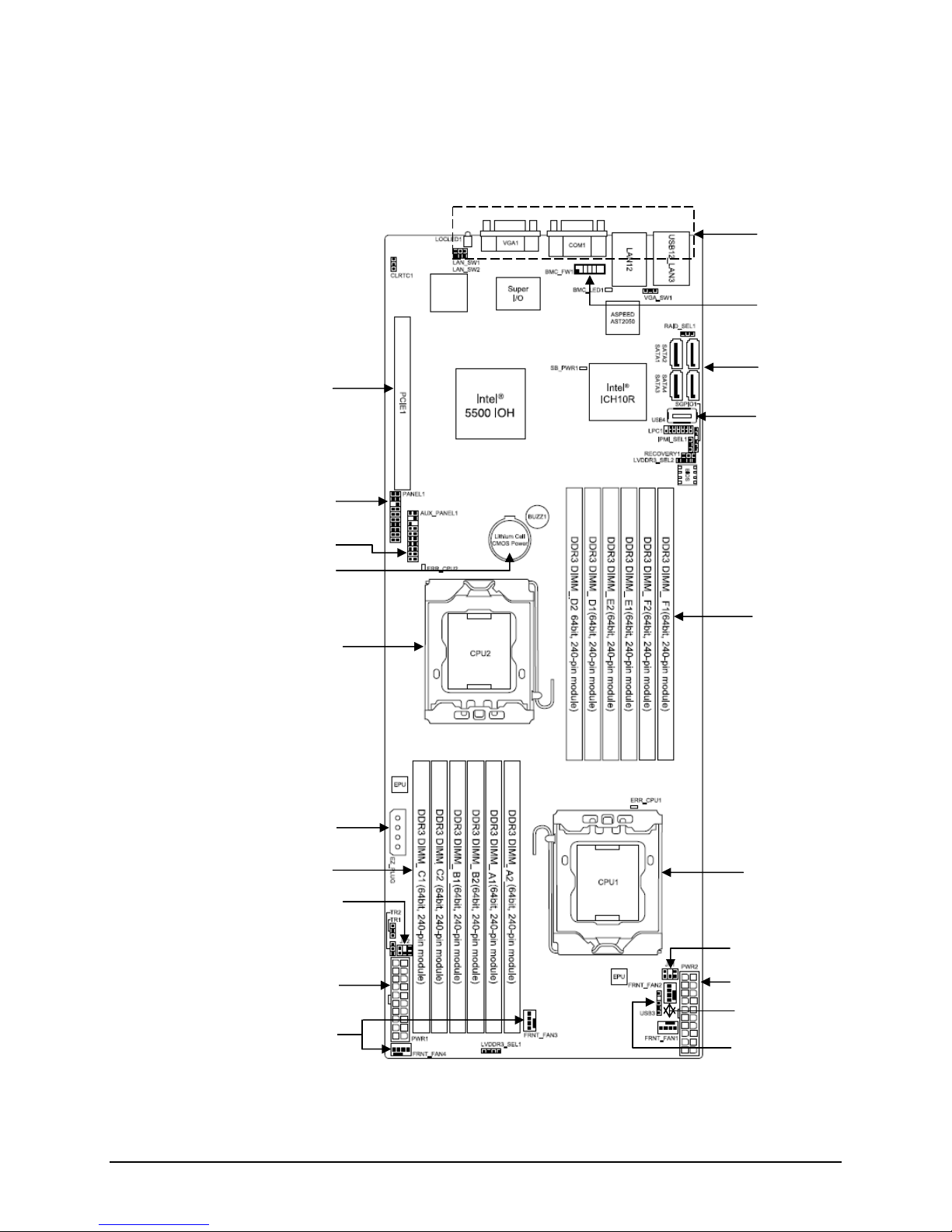
2.2.1 Server Board Connector and Component Layout
The following figure shows the board layout of the server board. Each connector and major
component is identified by letter, with a description of each given in Table 2.
A
B
Q
D
K
P
O
N
E
M
L
F
G
G
Figure 2. Intel® Server Board S5500HV Layout
5 Intel Confidential Revision 1.2
Intel order number E69391-006
H
I
H
I
J
Page 15
Overview Intel® Server Board S5500HV/Intel® Server System SR1670HV TPS
Table 2. Major Board Components
A Rear I/O Connectors K CPU 1 DIMM Slots (Slots A1– C2)
B BMC Management Module connector L Peripheral Drive Power Connector – 4 pin
C SATA Ports 1-4 M CPU 2 - LGA 1366 Socket
D Internal USB(4) 2.0 Port N CMOS Battery
E CPU 2 DIMM Slots (Slots D1 – F2) O Auxilary Front Panel Header
F CPU 1 - LGA 1366 Socket P Front Panel Header
G Power Supply SMBus - 2x3 Pin Header Q X16 GEN 2 PCI Express* Riser Card Slot
H Main Power Connector – 20 pin
I System Fan Connectors
J USB(3) 2.0 - 1x5 Pin Header
Description Description
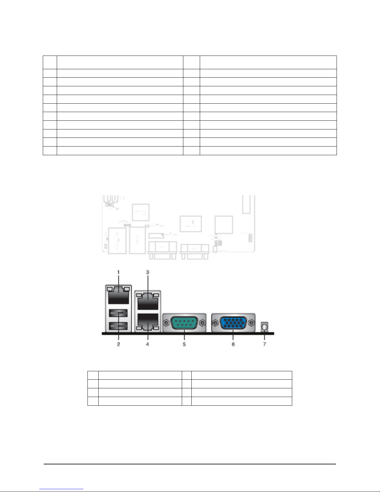
2.2.2 Server Board Rear I/O Layout
The following figure shows the layout of the rear I/O components for the server board.
1 BMC Management NIC Port 5 COM 1 Serial Port
2 Stacked USB 2.0 Ports 6 Video Connector
3 LAN 1 Port 10/100/1000 7 Blue System ID LED
4 LAN 2 Port 10/100/1000
Figure 3. Intel® Server Board S5500HV Rear I/O Layout
Revision 1.2 Intel Confidential 6
Intel order number E69391-006
Page 16
Intel® Server Board S5500HV/Intel® Server System SR1670HV TPS Functional Architecture
®
®
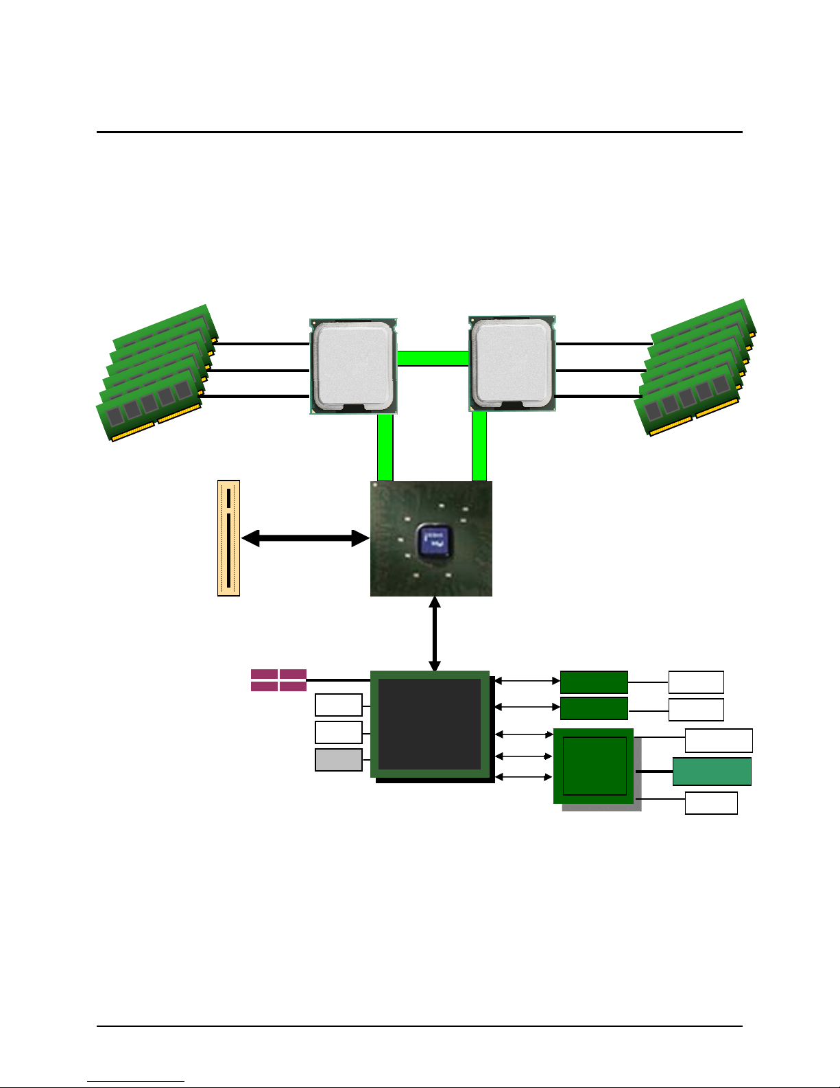
3. Functional Architecture
The Intel® Server Board S5500HV is based on Intel architecture with I/O and performance
features provided with the Intel
and the Intel
Interconnect (Intel
®
Xeon® processor 5500 Series and 5600 Series featuring Intel® QuickPath
®
QPI).
®
5500 Chipset I/O Hub (IOH), Intel® ICH10R I/O controller hub,
This chapter provides a high-level description of the functionality associated with each chipset
component and the architectural blocks that make up the server board.
DDR3 – C1, C2
DDR3 – B1, B2
DDR3 – A1, A2 DDR3 – D1, D2
Intel® Xeon®
Processor
5500 Series
EP
QuickPath
Intel® Xeon®
Processor
5500 Series
EP
DDR3 – F1, F2
DDR3 – E1, E2
QuickPath
CPU 2
X16 Riser Card Slot
PCI Express* Gen 2
CPU 1
QuickPath
Intel
X16
5500 Chipset IOH
ESI
4 x SATA
USB 1
USB 2
USB 3
Intel
ICH10R
X1
X1
PCI 33
LPC
USB
®
Figure 4. Intel
Server Board S5500HV Functional Block Diagram
3.1 Processor Support
The server board supports the following:
Two on board FC-LGA 1366 socket B package processor sockets.
AST2050
MGNT NIC
BMC Module
7 Intel Confidential Revision 1.2
Intel order number E69391-006
Page 17

Functional Architecture Intel® Server Board S5500HV/Intel® Server System SR1670HV TPS
Functional support for one or two Intel® Xeon® Processors 5500 Series and 5600 Series
with 4.8 GT/s, 5.86 GT/s or 6.4 GT/s with Intel
®
QuickPath Interconnect.
Up to 130 Watt Thermal Design Power (TDP)
NOTE: Previous generations of the Intel
®
Xeon® processors are not supported on this server
board.
3.1.1 Intel
®
Xeon® Processor 5500 Series and 5600 Series
The Intel® Xeon® Processor 5500 Series and 5600 Series are new micro-architecture based on
Intel 45nm and 32nm process technology. The enhancements of the Intel Xeon Processor 5500
Series and 5600 Series are a result of six major technology developments:
New processor architecture
Intel
®
QuickPath Technology
Hyper-threading
Intelligent power
Turbo boost
Integrated Memory Controller
The processor supports all the existing Streaming SIMD Extensions 2 (SSE2), Streaming SIMD
Extensions 3 (SSE3) and Streaming SIMD Extensions 4 (SSE4); in addition to several
advanced technologies including:
Execute Disable Bit
Intel
Enhanced Intel SpeedStep
Intel
Simultaneous Multithreading.
®
Extended Memory 64 Technology (Intel® EM64T)
®
Technology
®
Virtualization Technology (Intel® VT)
3.1.1.1 New Processor Architecture
®
The Intel
Xeon® Processor 5500 Series and 5600 Series feature several new architectural
innovations, including:
A distinction between the core and “uncore” in terms of chip design
Four distinct cores per processor
New Level 3 shared Smart Cache
More parallelism: 33% more micro-ops over 45nm Intel
Enhanced algorithms and branch prediction capabilities
High bandwidth Intel
An Integrated Memory Controller
Revision 1.2 Intel Confidential 8
Intel order number E69391-006
®
Xeon® Processor 5400 Series
®
QuickPath Memory Controller: up to 25.6GB/s
Page 18
Intel® Server Board S5500HV/Intel® Server System SR1670HV TPS Functional Architecture
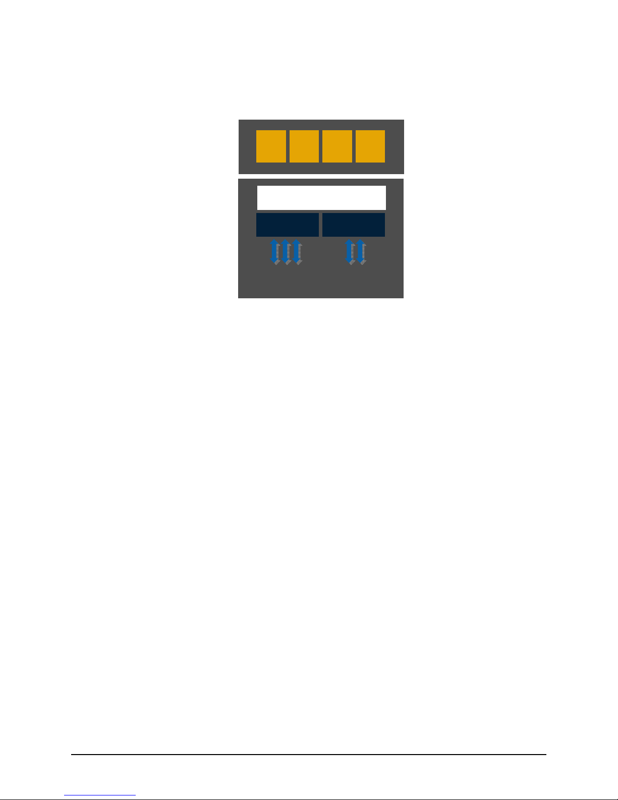
Core Core Core Core
8M Shared Cache
Memory
Controller
3x DDR3
Channels
Link
Controller
2x Intel
QuickPath
interconnects
Core
Uncore
Figure 5 Processor Architecture
The Intel Smart Cache architecture features a new three-level hierarchy.
st
1
Level Cache
32 KB instruction cache
32 KB data cache (which supports more L1 misses in parallel than Core 2)
nd
Level Cache
2
New cache introduced in the Intel
®
Xeon® Processor 5500 Series and 5600 Series
Unified (holds code and data)
256KB per core
Performance: Very low latency (new dedicated L2 cache improves performance by
reducing latency to frequently used data)
Scalability: As core count increases, pressure on shared cache is reduced
rd
Level Cache
3
Shared across all cores
Size depends on number of cores
Quad-core: up to 8 MB
Scalability: built to vary size with varied core counts with the ability to easily increase L3
size in future parts
Inclusive cache policy for best performance
The data residing in L1/L2 must be present in 3rd level
Shares memory among all cores
9 Intel Confidential Revision 1.2
Intel order number E69391-006
Page 19

Functional Architecture Intel® Server Board S5500HV/Intel® Server System SR1670HV TPS
3.1.1.2 Intel
®
QPI is a cache-coherent, link-based interconnect specification for processor, chipset, and
Intel
I/O bridge components. Intel
platforms spanning IA-32 and Intel
®
QuickPath Interconnect (Intel® QPI)
®
QPI can be used in a wide variety of desktop, mobile, and server
®
Itanium® architectures. Intel® QPI also provides support for
high-performance I/O transfer between I/O nodes. It allows connection to standard I/O buses
such as PCI Express*, PCI-X, PCI (including peer-to-peer communication support), AGP, etc.,
through appropriate bridges.
Each Intel
and receiver, plus a differential forwarded clock. A full width Intel
signals (20 differential pairs in each direction) plus a forwarded differential clock in each
direction. Each Intel
links, one going to the other processor and the other to the Intel
In the current implementation, Intel
6.4 GT/s. Intel
- 5 lanes) independently in each direction between a pair of devices communicating via Intel
®
QPI link consists of 20 pairs of uni-directional differential lanes for the transmitter
®
Xeon® Processor 5500 Series and 5600 Series supports two Intel® QPI
®
®
QPI ports operate at multiple lane widths (full - 20 lanes, half - 10 lanes, quarter
QPI ports are capable of operating at transfer rates of up to
®
QPI link pair consists of 84
®
5500 Chipset IOH.
®
QPI. The server board supports full width communication only.
3.1.1.3 Intel
®
Hyper-Threading Technology lets you run two threads at the same time per core. This
Intel
®
Hyper-Threading Technology
capability lets the processor take advantage of a 4-wide execution engine, effectively hiding the
latency of a single thread. However, the data residing in L1/L2 must be present in 3rd level
cache.
This is the most power efficient performance feature of the Intel
®
Xeon® Processor 5500 Series
and 5600 Series. It’s very efficient performance boost that comes at a very low die area cost.
Depending on the application, it can provide significant performance benefit and is much more
efficient than adding an entire core. It supports larger caches and provides for massive memory
bandwidth.
3.1.1.4 Intel
®
The Intel
Xeon® Processor 5500 Series and 5600 Series feature two Intel® Intelligent Power
®
Intelligent Power Technology
Technologies:
Integrated Power Gates - this feature lets individual idle cores reduce power to nearly zero
independently. Core power can be controlled automatically or manually.
Automated Low Power States – this feature allows for more and lower CPU power states with
reduced latency during transitions. Also, it now features power management on memory and I/O
chip as well as the processor. This adjusts system power consumption based on real-time loads.
3.1.1.5 Turbo Mode
®
Intel
Turbo Boost Technology opportunistically and automatically allows the processor to run
faster than the marked frequency if the part is operating below power, temperature, and current
limits. This can result in increased performance of both multi-threaded and single threaded
workloads.
Revision 1.2 Intel Confidential 10
Intel order number E69391-006
Page 20

Intel® Server Board S5500HV/Intel® Server System SR1670HV TPS Functional Architecture
Turbo boost operation:
Operates under OS control – only entered when OS requests higher performance state
(P0).
Turbo Boost availability is independent of the number of active cores
Max Turbo boost frequency is dependent on the number of active cores and varies by
processor configuration.
Amount of time the system spends in Turbo Boost will depend on the workload,
operating environment, and platform design.
Turbo Boost can be enabled or disabled by BIOS.
3.1.1.6 Integrated Memory Controller
®
The Intel
as the Intel
5500 Chipset Series employs a new design where the memory controller, referred to
®
QuickPath Memory Controller, is now embedded as part of the processor
architecture.
The Intel
®
QuickPath Memory Controller provides up to three memory channels per processor
supporting up to 32 GB/s bandwidth per memory controller. Supported memory follows the
DDR3 specification and supports the following characteristics:
800MHz, 1066MHz and 1333MHz operating frequencies
Single-rank (SR), dual-rank (DR) and quad-rank (QR)
Registered DIMM (RDIMM) or Unbuffered DIMM (UDIMM)
3.1.2
Processor Population Rules
Note: Although the server board does support dual-processor configurations consisting of
different processors that meet the defined criteria below, Intel does not perform validation
testing of this configuation. For optimal system performance in dual-processor configurations,
Intel recommends that identical processors be installed.
When using a single processor configuration, the processor can be installed into either CPU1 or
CPU2 processor sockets.
When two processors are installed, the following population rules apply:
Both processors must have the same Intel
Both processors must have the same core frequency
Both processors must have the same internal cache sizes
Both processors must have the same Thermal Design Power (TDP - Watts) rating
Processor stepping within a common processor family can be mixed as long as it is
®
QuickPath Interconnect frequency
listed in the processor specification updates published by Intel Corporation.
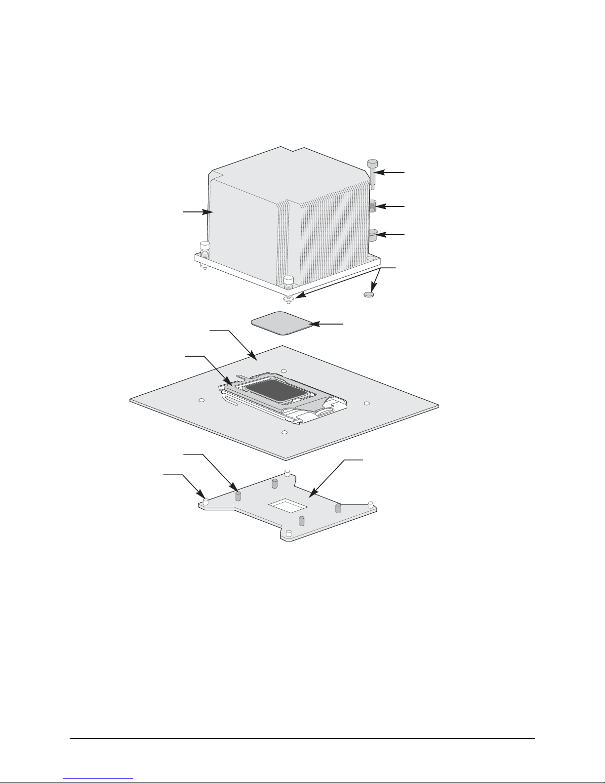
3.1.3
Unified Retention System Support
The server board complies with Intel’s Unified Retention System (URS) and the Unified
Backplate Assembly. The server board ships with a made-up assembly of Independent Loading
Mechanism (ILM) and Unified Backplate for each processor socket.
11 Intel Confidential Revision 1.2
Intel order number E69391-006
Page 21
Functional Architecture Intel® Server Board S5500HV/Intel® Server System SR1670HV TPS
The URS retention transfers load to the server board through the unified backplate assembly.
The URS spring, captive in the heatsink, provides the necessary compressive load for the
thermal interface material. All components of the URS heatsink solution are captive to the
heatsink and only require a Philips* screwdriver to attach to the unified backplate assembly.
See the following figure for the stacking order of the URS components.
Screw
Heatsink
ILM and Socket
ILM Attach Studs
Heatsink
Attach Studs
Server Board
Compression Spring
Retention Cup
Retaining Ring
Thermal Interface Material (TIM)
Unified Backplate
Figure 6. Unified Retention System and Unified Backplate Assembly
3.2 Intel
®
QuickPath Memory Controller and Memory Subsystem
The Intel® QuickPath Memory Controller provides up to three memory channels per processor
supporting up to 32 GB/s bandwidth per memory controller. Supported memory follows the
DDR3 specification and supports the following characteristics:
800MHz, 1066MHz and 1333MHz operating frequencies
Single-rank (SR), dual-rank (DR) and quad-rank (QR)
Revision 1.2 Intel Confidential 12
Intel order number E69391-006
AF002699
Page 22
Intel® Server Board S5500HV/Intel® Server System SR1670HV TPS Functional Architecture
0
Registered DIMM (RDIMM) or Unbuffered DIMM (UDIMM)
RDIMMs must be ECC only
UDIMMs can be ECC or non-ECC and can be mixed within a common configuration
The Channel Independent mode is the only memory RAS mode that supports non-
ECC DIMMs.
The presence of a single non-ECC UDIMM results in the disabling of ECC
functionality.
RDIMMs and UDIMMs cannot be mixed within a common system memory
configuration
Note:
Although non-ECC memory can be used on this server board, Intel does not validate and
strongly discourages their use in a working server environment.
The following table shows the maximum memory amounts possible using RDIMM type memory:
Single Rank RDIMMs
800 MHz and 1066 MHz
Dual Rank RDIMMs
800 MHz and 1066 MHz
Quad Rank RDIMMs (1)
800 MHz only
48 GB
(12x 4GB DIMMs)
96 GB
(12x 8GB DIMMs)
96 GB
(12x 8GB DIMMs)
NOTE: (1) Due to thermal requirements needed to support Quad Rank x4 DDR3 DIMMs, this
memory type is not supported in the Intel® Server System SR1670HV. Support for this memory
type should be verified with other server chassis/system manufacturers planning to support this
server board.
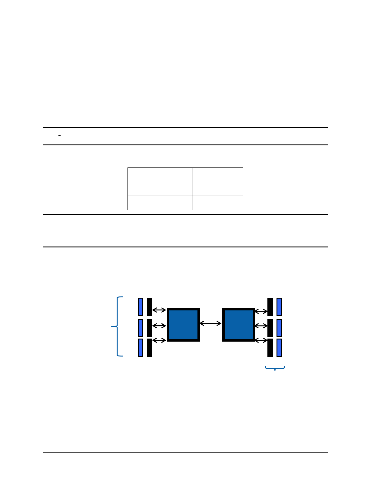
3.2.1 Intel
®
Server Board S5500HV Memory Support
The Intel® Server Board S5500HV provides six DIMM slots across 3 memory channels per
processor, for a total of twelve DIMM slots.
0
1
2
3 channels per
CPU
1
2
Intel®
®
Xeon
Processo
r 5500
CPU 1
QPI
Intel®
Xeon
Processo
r 5500
CPU 2
®
Figure 7. Conceptual Memory Layout Diagram
13 Intel Confidential Revision 1.2
Intel order number E69391-006
1 2
2 1
2 DIMMs per
channel
Page 23
Functional Architecture Intel® Server Board S5500HV/Intel® Server System SR1670HV TPS
A
A
The nomenclature for DIMM slots implemented on the Intel® Server Board S5500HV is detailed
in the following figure.
Processor Socket 1 Processor Socket 2
Channel 0
(A)
A1 A2 B1 B2 C1 C2 D1 D2 E1 E2 F1 F2
Channel 1 (B) Channel 2
(C)
Channel 0
(D)
Channel 1 (E) Channel 2
(F)
Figure 8. DIMM Slot Nomenclature
On the Intel® Server Board S5500HV the DIMM slots are identified as shown below:
D2
D1
E2
E1
F2
F1
CPU 2
Intel® Xeon®
Processor
5500 Series
Intel® Xeon®
Processor
5500 Series
CPU 1
Figure 9. Intel Server Board S5500HV Memory Slot Layout
C2B1B2
C1
2
1
Note: Memory is only populated using DIMM slots associated with a given installed processor.
Ie.) With only one processor installed, only the DIMM slots associated with that processor
should be populated. Memory installed into DIMM slots for a processor that is not installed are
non-functional.
DIMMs are organized into physical slots on DDR3 memory channels that belong to
processor sockets.
The memory channels from processor socket 1 are identified as Channels A, B, and C.
The memory channels from processor socket 2 are identified as Channels D, E, and F.
Revision 1.2 Intel Confidential 14
Intel order number E69391-006
Page 24
Intel® Server Board S5500HV/Intel® Server System SR1670HV TPS Functional Architecture
The memory slots associated with a given processor are unavailable if the given
processor socket is not populated.
A processor may be installed without populating the associated memory slots provided a
second processor is installed with associated memory. In this case, the memory is
shared by the processors. However, this is not a recommended configuration due to the
associated latency which will affect performance.
Processor sockets are self-contained and autonomous. However, all memory subsystem
support (i.e., Memory RAS, Error Management, etc.) in the BIOS setup are applied
commonly across processor sockets.
3.2.1.1 Memory Population Rules
DIMM population requirements are dependent upon the number of slots per channel; the
number of DIMMs installed; and rank type. When installing memory consider the following:
Populate DIMMs by channel starting with the Blue slot farthest from the CPU
All channels in a system will run at the fastest common frequency
RDIMMs and UDIMMs may not be mixed
If two 1333 MHz capable UDIMMs or RDIMMs is detected in the same channel, BIOS
will flag this as a warning and force the speed down to 1066 MHz.
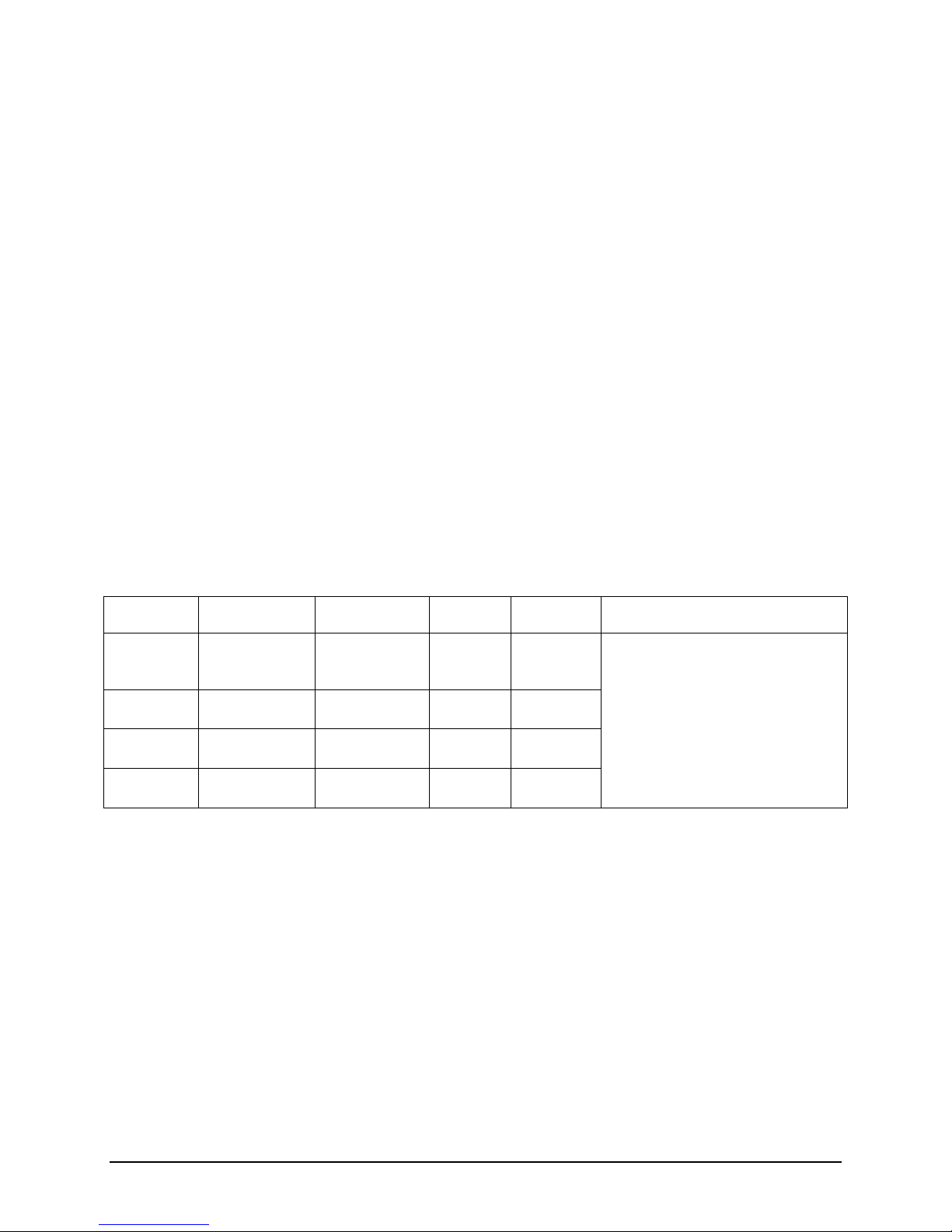
3.2.1.1.1 Supported RDIMM configurations:
Table 3 Supported RDIMM configurations
DIMM Slots
per Channel
2 1 Registered
2 1 Registered
2 2 Registered
2 2 Registered
DIMMs Populated
per Channel
DIMM Type Speeds Ranks per
DIMM
DDR3 ECC
DDR3 ECC
DDR3 ECC
DDR3 ECC
800,
1066,
1333
800, 1066 QR Only
800, 1066 Mixing SR,
800 Mixing SR,
SR or DR
DR
DR, QR
Population Rules
1. Any combination of x4 and x8
RDIMMs, with 1Gb or 2Gb DRAM
density
256 Mb, 512 Mb and 4 Gb DRAM technologies and x16 DRAM on RDIMM are NOT
supported
If a quad rank RDIMM is mixed with a single rank or dual rank DIMM on given channel,
the quad rank DIMM must be populated in the lowest numbered slot.
15 Intel Confidential Revision 1.2
Intel order number E69391-006
Page 25
Functional Architecture Intel® Server Board S5500HV/Intel® Server System SR1670HV TPS
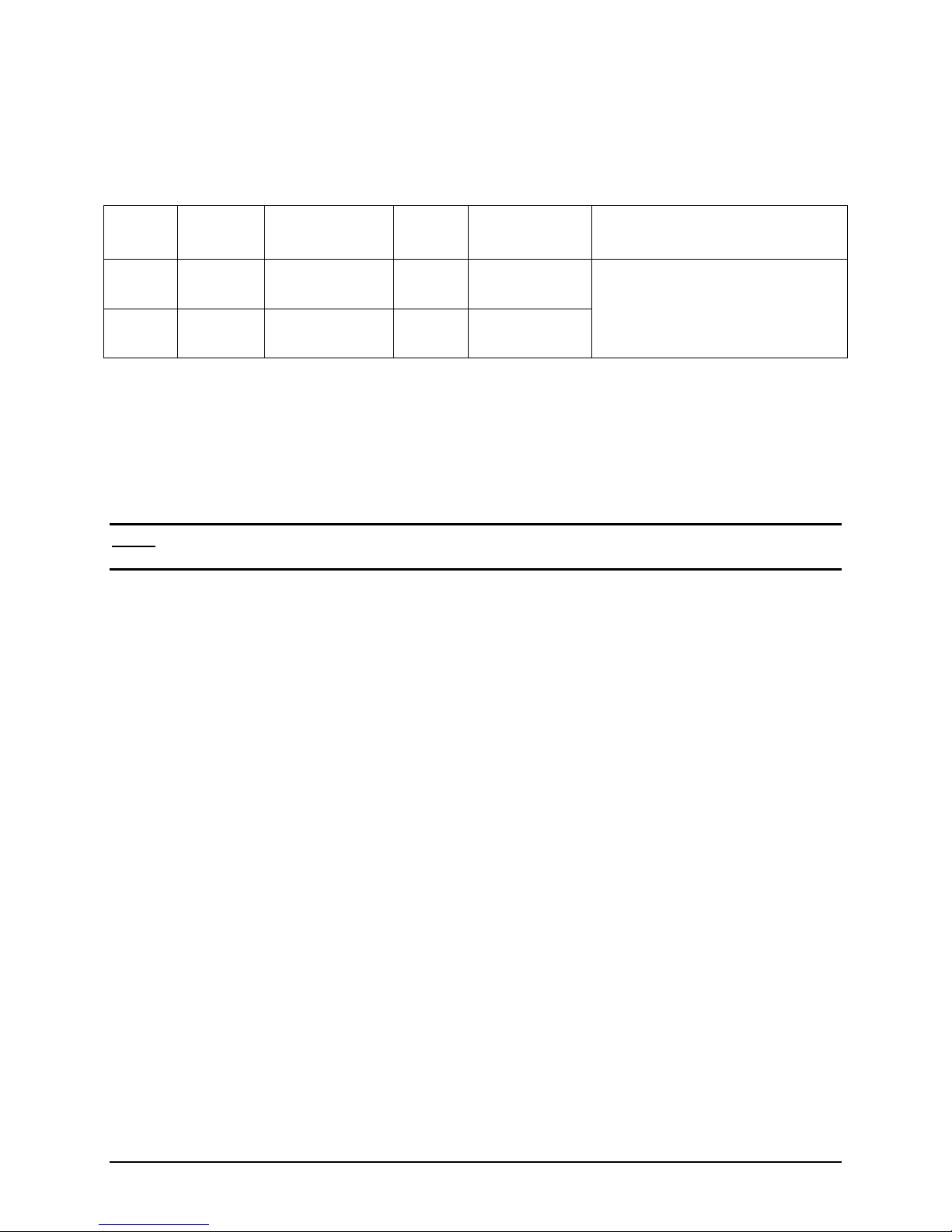
3.2.1.1.2 Supported UDIMM configurations:
Table 4 Supported UDIMM configurations
DIMM
Slots per
Channel
2 1 Unbuffered DDR3
2 2 Unbuffered DDR3
DIMMs
Populated
per Channel
DIMM Type Speeds Ranks per DIMM Population Rules
SR or DR
Mixing SR, DR
1. Any combination of x8 UDIMMs with
1Gb or 2Gb DRAM Density
(with or without
ECC)
(with or without
ECC)
800,
1066,
1333
800,
1066
256 Mb, 512 Mb and 4 Gb DRAM technologies; x4 DRAM on UDIMM and Quad rank
UDIMM are not supported
Mixing ECC and non-ECC UDIMMs anywhere on the platform will force system to run in
non-ECC mode
No RAS support for non-ECC UDIMMs
No x4 SDDC support with UDIMM w/ECC, however x8 SDDC is supported in lock step
mode with x8 UDIMMs w/ECC
Note:
Although non-ECC memory can be used on this server board, Intel does not plan to
validate and strongly discourages their use in a working server environment.
When installing DIMMs, the following population rules should be followed to deliver best
performance
Maximize number of channels populated first
Balanced DIMM population across channels and sockets.
Revision 1.2 Intel Confidential 16
Intel order number E69391-006
Page 26
Intel® Server Board S5500HV/Intel® Server System SR1670HV TPS Functional Architecture
;
;
;
- -
-
-
;
;
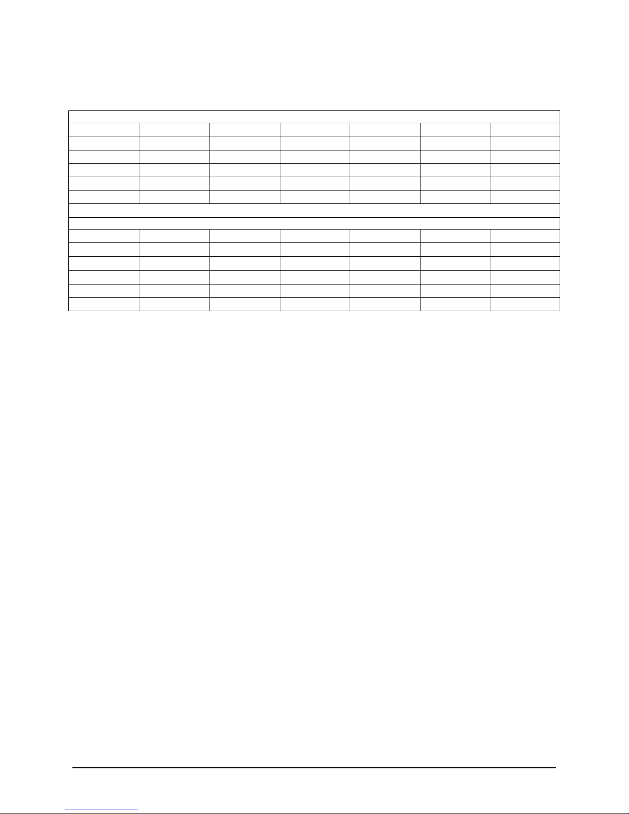
CPU 1 Configuration
1 DIMM
2 DIMMs
3 DIMMs
4 DIMMs
6 DIMMs
Table 5 Memory Population Table
DIMM_A2 DIMM_A1 DIMM_B2 DIMM_B1 DIMM_C2 DIMM_C1
-
-
-
; ;
;
;
;
- - - -
-
-
-
; ; ; ; ; ;
CPU 2 Configuration
1 DIMM
2 DIMMs
3 DIMMs
4 DIMMs
6 DIMMs
DIMM_D2 DIMM_D1 DIMM_E2 DIMM_E1 DIMM_F2 DIMM_F1
-
-
-
; ;
;
;
;
- - - -
-
-
-
;
;
;
- -
-
-
;
;
; ; ; ; ; ;
With two processors installed, the system will operate if only the DIMM slots of one processor
are populated. In this case, memory is shared between the two processors. However, due to the
associated latency of this configuration, this is NOT a recommended operating mode.
3.2.1.2 Memory RAS Modes
The server board supports the following memory RAS Modes:
Independent Channel Mode
Mirrored Channel Mode
Mirrored Channel Mode requires that all installed DIMMs support ECC and that there be
matching DIMM populations between channels. Matching DIMMs must meet the following
criteria: DIMM size, DIMM organization (rank, banks, rows, columns). DIMM timings do not have
to match, however, timings will be set to support all DIMMs populated.
Independent channel mode is the only memory RAS mode that supports either non-ECC or
ECC DIMMs.
Independent Channel Mode
In the Channel Independent mode, channels can be populated in any order (e.g., channels B
and C can be populated while channel A is empty). All three channels may be populated in any
order and have no matching requirements. All channels must run at the same interface
frequency, but individual channels may run at different DIMM timings (RAS latency, CAS
latency, and so on).
The single channel mode is established using the Channel Independent mode by populating
DIMM slots from channel A only.
17 Intel Confidential Revision 1.2
Intel order number E69391-006
Page 27
Functional Architecture Intel® Server Board S5500HV/Intel® Server System SR1670HV TPS
A
A
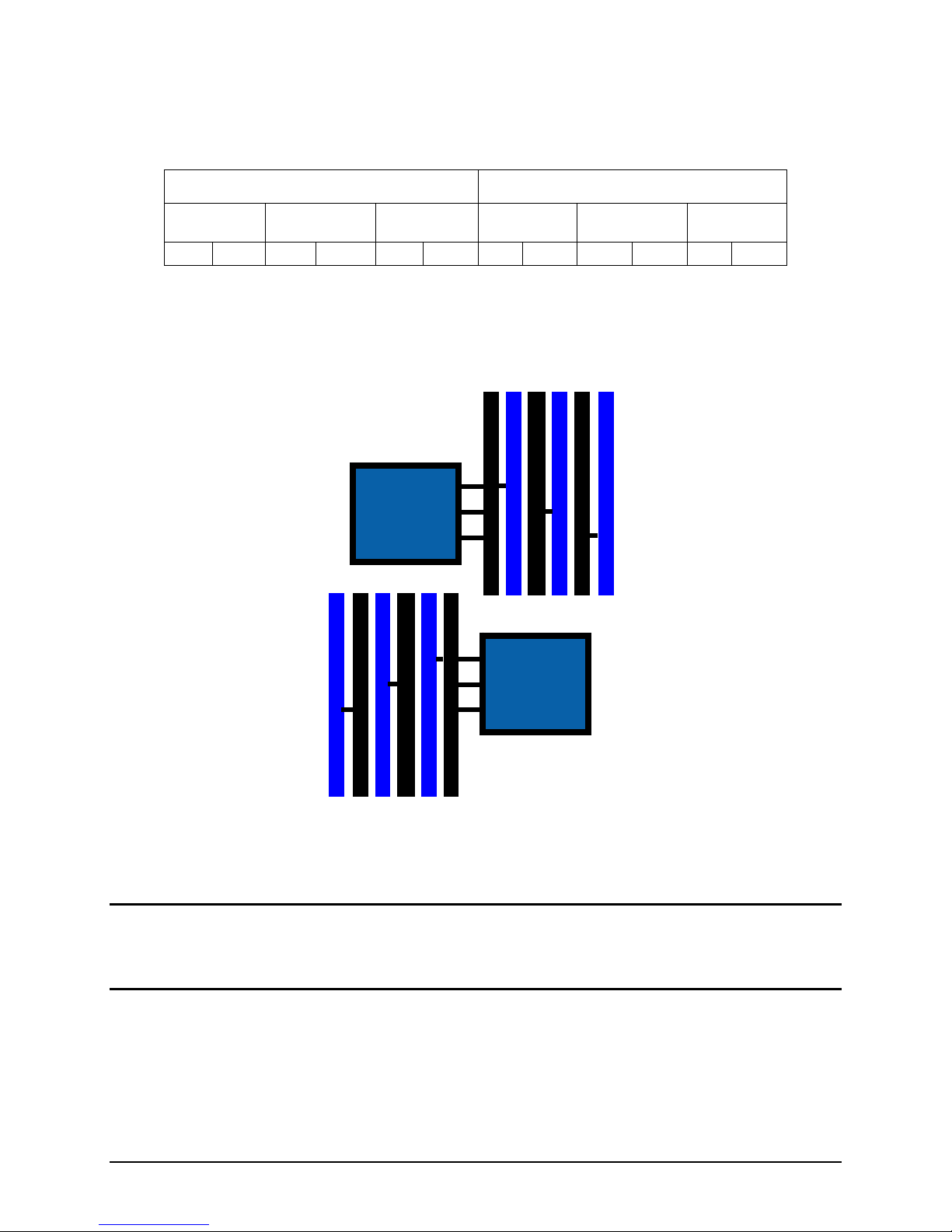
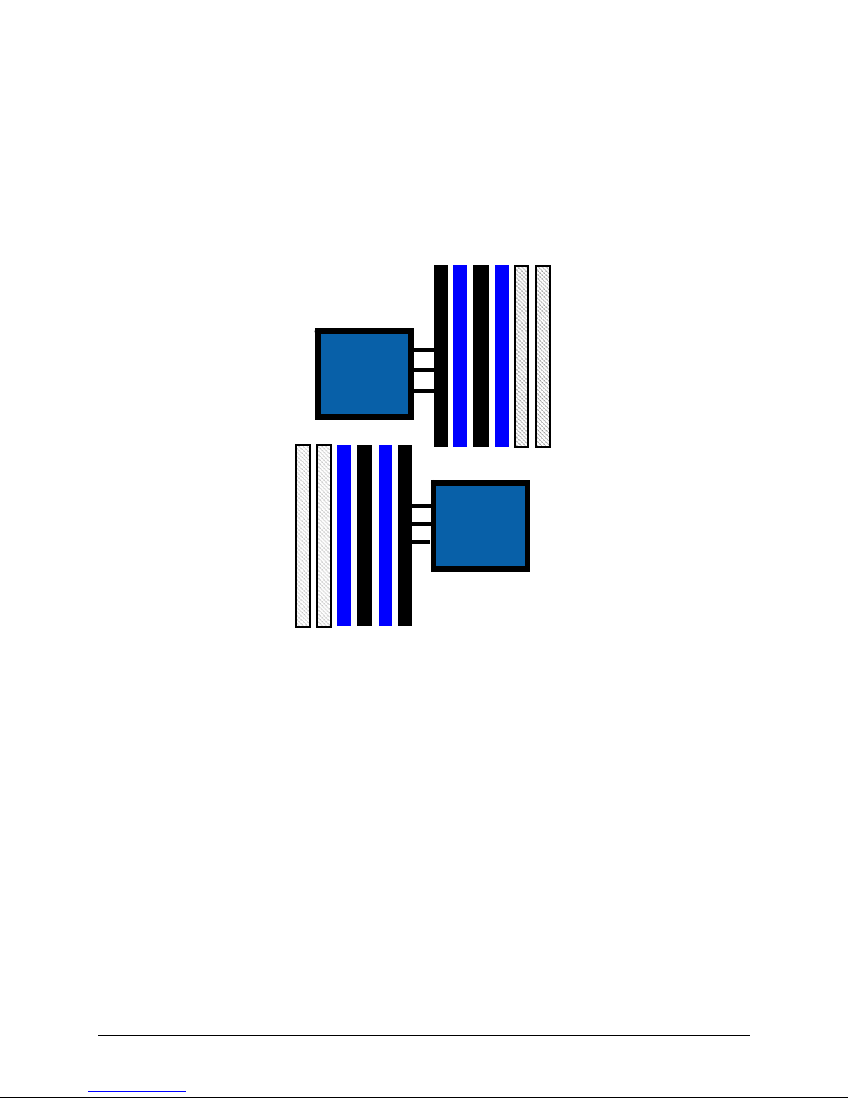
Mirrored Channel Mode
In Mirrored Channel Mode, the memory controller supports mirroring across channels, but not
across CPU sockets. The contents are mirrored between the first 2 channels of a given
processor. For CPU1, mirrored slot pairs include {A1, B1} and {A2, B2}. For CPU2, the mirrored
slot pairs include {D1, E1} and {D2, E2}. The sockets of the 3rd channel of each CPU are not
used in this mode.
D2
D1
E2
E1
F2
F1
Intel® Xeon®
CPU 2
Processor
5500 Series
Intel® Xeon®
Processor
C1
C2
B1
B2
1
5500 Series
2
CPU 1
Figure 10. Mirror Channel Mode Memory Population
Mirrored channel mode requires the following memory population rules:
Channel 0 and Channel 1 of a given processor must be populated identically.
DIMM slot populations within a channel do not have to be identical, but the same DIMM
slot location across Channel 0 and Channel 1 must be populated the same.
For example; DIMM slots A1 and B1 must have identical DIMMs installed to be
mirrored together. DIMM slots A2 and B2 must have identical DIMMs installed to be
mirrored together. However the DIMMs used in mirrored pair {A1, B1} can be
different than those used in mirrored pair {A2, B2}.
With two processors installed, DIMM slots associated with each processor must have a
valid mirroring configuration for memory channels 0 and 1. However, the memory
configuration of each processor can be different from the other.
The exception to this rule is that one processor has no memory installed. Because of
the associated latency, this is NOT a recommended operating mode.
Revision 1.2 Intel Confidential 18
Intel order number E69391-006
Page 28
Intel® Server Board S5500HV/Intel® Server System SR1670HV TPS Functional Architecture
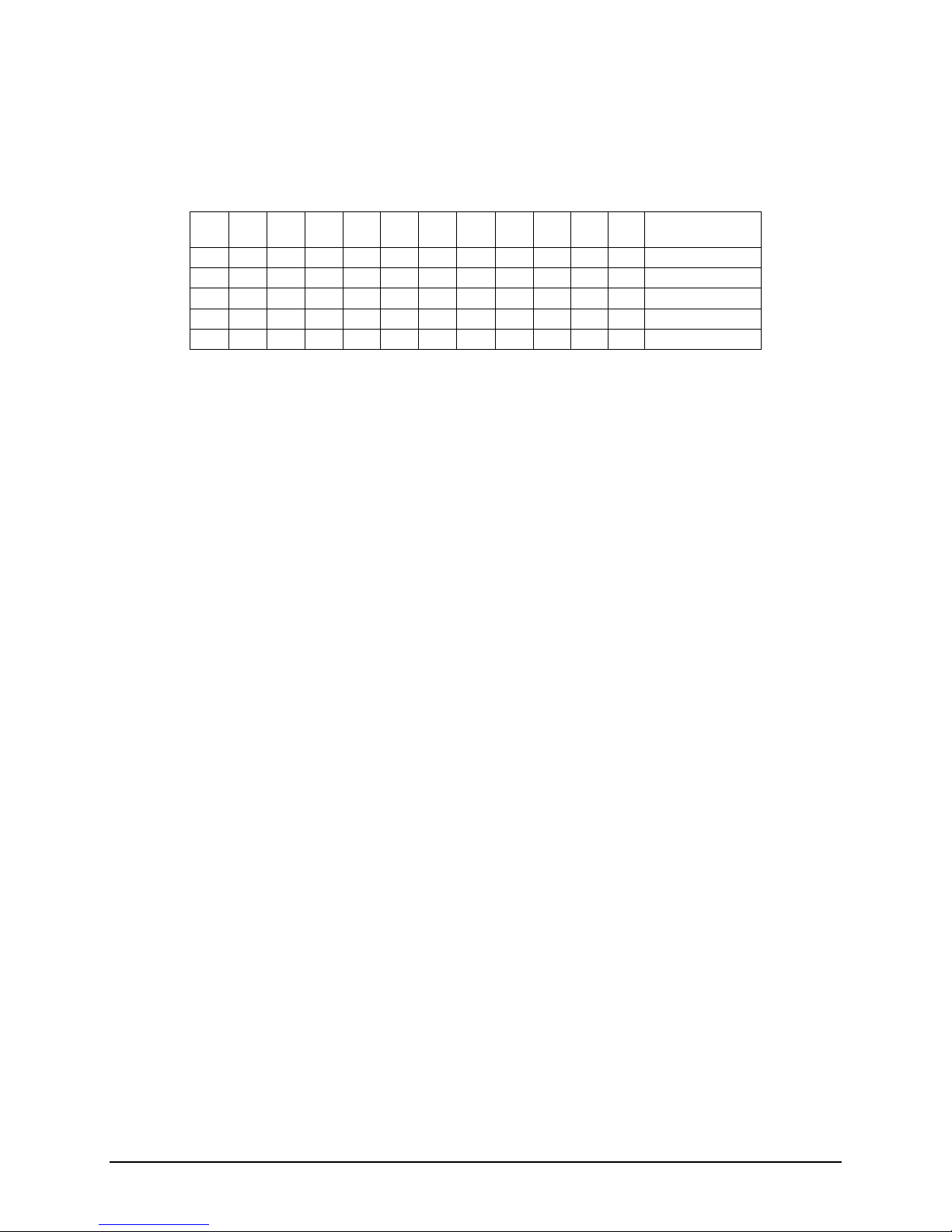
The following table illustrates possible DIMM configurations that can be mirrored, with the
following assumptions: Two processors are installed; all installed DIMMs are identical.
Table 6. Supported Mirrored DIMM Population
A1 A2 B1 B2 C1 C2 D1 D2 E1 E2 F1 F2 Mirroring
Possible?
;
;
;
;
; ; ; ;
; ; ; ;
; ; ; ;
;
;
;
; ; ; ;
;
Yes
Yes
Yes
Yes
Yes
3.3 Intel
The Intel
components and Intel
®
5500 Chipset IOH
®
5500 Chipset I/O Hub (IOH) provides a connection point between various I/O
®
QuickPath Interconnect (Intel® QPI) based processors. It is capable of
interfacing with up to 24 PCI Express* lanes, which can be configured in various combinations
of x4, x8, x16 and limited x2 and x1 devices.
On the Intel Server Board S5500HV the IOH provides the following:
Two Intel
One X16 PCI Express* Gen 2 port supporting a single PCI Express Gen2 compliant X16
®
QuickPath Interconnect (Intel® QPI) interfaces
riser card slot. (Compliant to the PCI Express Base Specification, Revision 2.0)
One X4 ESI link interface to the I/O controller hub Intel
3.4 Intel
®
82801Jx I/O Controller Hub (ICH10R)
®
ICH10R
The server board utilizes features of the Intel® 82801Jx I/O Controller Hub (ICH10R). Supported
features include the following:
PCI Express* Base Specification, Revision 1.1 support
PCI Local Bus Specification, Revision 2.3 support for 33-MHz PCI operations (supports
up to four REQ#/GNT# pairs)
ACPI Power Management Logic Support, Revision 3.0a
Enhanced DMA controller, interrupt controller, and timer functions
Integrated Serial ATA host controllers with independent DMA operation on up to four
ports and AHCI support
USB host interface with support for four USB 2.0 ports; Two external, two internal
System Management Bus (SMBus) Specification, Version 2.0 with additional support for
2
I
C devices
Low Pin Count (LPC) interface support
Firmware Hub (FWH) interface support
Serial Peripheral Interface (SPI) support
19 Intel Confidential Revision 1.2
Intel order number E69391-006
Page 29

Functional Architecture Intel® Server Board S5500HV/Intel® Server System SR1670HV TPS
(
3.4.1.1 Serial ATA Support
The ICH10R has an integrated Serial ATA (SATA) controller that supports independent DMA
operation on four ports with data transfer rates of up to 3.0 Gb/s. The four SATA ports on the
server board are numbered SATA-1 through SATA-4. The SATA ports can be enabled or
disabled and/or configured by accessing the BIOS setup utility during POST.
3.4.1.2 Integrated RAID Support
The server board has embedded support for two RAID options:
Intel
®
Matrix Storage Manager with support for RAID levels 0, 1, 5, and 10 (Windows*
support only)
LSI* MegaRAID (Default) with support for RAID levels 0, 1, and 10 (Windows* and Linux)
By default the server board is configured to support the LSI* MegaRAID option. To change this,
a jumper block on the board needs to be changed. The following diagram shows the location of
the jumper block and its settings.
1
2
3
Default)
LSI
1
2
3
Intel
By default, BIOS does NOT enable RAID support. To enable this feature, on option in BIOS
setup must be set as described in the following procedure:
1. Enter BIOS Setup (F2 Key) during POST
2. Go to the MAIN menu > IDE Configuration, and press <Enter>
3. Set the Configure SATA As option to [RAID]
4. Save changes and then exit BIOS Setup
Note: Refer to Intel
Revision 1.2 Intel Confidential 20
Intel order number E69391-006
®
Server System SR1670HV Service Guide for RAID setup information
Figure 11. RAID Option Jumper Block
Page 30

Intel® Server Board S5500HV/Intel® Server System SR1670HV TPS Functional Architecture
r
3.4.2 USB 2.0 Support
The USB controller functionality integrated into ICH10R provides the server board with an
interface for 4 USB 2.0 ports. All ports are high-speed, full-speed and low-speed capable.
Two external connectors are located on the back edge of the server board.
Two internal connectors (A-Type USB 4, 5x1 header USB 3) allow for optional USB
support
USB 4
Type 4 device
connecto
Figure 12. Internal USB Port Locations
USB 3
Power USB Port A-
USB Port A+
GND
3.4.3 Keyboard and Mouse Support
The server board does not support PS/2 interface keyboards and mice. However, the system
BIOS recognizes USB specification-compliant keyboard and mice.
3.5 Network Interface Controller (NIC)
This server board supports two external Gigabit Ethernet ports in a stacked housing on the back
edge of the server board. The network interface is provided using two on-board Intel
Gigabit Ethernet Controllers supporting 10/100/1000 Mbps operation.
The Intel
1000BASE-T, 100BASE-TX, and 10BASE-T applications (802.3, 802.3u, and 802.3ab).
Each network interface controller (NIC) drives two status LEDs located on each external
network interface connector. The activity/link LED (at the left of the connector) indicates network
connection when on, and transmit/receive activity when blinking. The speed LED (at the right of
21 Intel Confidential Revision 1.2
Intel order number E69391-006
®
82574L device provides MDI (copper) standard IEEE 802.3 Ethernet interface for
®
82574L
Page 31

Functional Architecture Intel® Server Board S5500HV/Intel® Server System SR1670HV TPS
the connector) indicates 1000-Mbps operation when green, 100-Mbps operation when orange,
and 10-Mbps when off. The following table provides an overview of the LEDs.
Act/Link
LED
Speed
LED
Table 7. NIC Status LEDs
Act/Link LED Speed LED
Status Description Status Description
OFF No Link OFF 10 Mbps connection
GREEN Linked ORANGE 100 Mbps connection
BLINKING Data Activity GREEN 1000 Mbps connection
Each LAN port can be enabled (default) or disabled via a jumper block, identified in the
following diagram.
NIC 1
NIC 2
1
2
Enabled
1
2
Disabled
Figure 13. NIC Enable/Disabled Jumper Block
Revision 1.2 Intel Confidential 22
Intel order number E69391-006
Page 32

Intel® Server Board S5500HV/Intel® Server System SR1670HV TPS Functional Architecture
3.6 ASPEED* AST2050 Graphics and Remote Management Processor
This server board utilizes the graphics and baseboard management features of the ASPEED*
AST2050 Graphics and Remote Management Processor. Features utilized include:
Embedded 2D VGA Controller
Baseboard Management Controller
10/100 Mbps MAC (option)
3.6.1
Video Support
Video support on this server board is provided using the video controller features embedded in
the ASPEED* AST2050. Video support includes a 2D VGA controller capable of supporting
video resolutions up to and including 1600x1200@60Hz 16bpp.
The video is accessed using a standard 15-pin VGA connector found on the back edge of the
server board. The on-board video controller can be enabled (default) or disabled via a jumper
on the baseboard, identified in the following diagram:
1
2
Enable
(Default)
1
2
Disable
Figure 14. Video Enable/Disable Jumper Block
3.6.2 Baseboard Management Controller & BMC Module
This server board uses the Baseboard Management Controller feature of the ASPEED
AST2050 along with a Winbond* 83795ADG hardware monitoring chip to monitor various server
board sensors including Processor Temp, Fan Tach, and DC Voltages. Sensor data can be
accessed in-band with or without the included Baseboard Management Module. For out-of-band
access to this sensor data, the included Baseboard Management Module must be installed.
23 Intel Confidential Revision 1.2
Intel order number E69391-006
Page 33

Functional Architecture Intel® Server Board S5500HV/Intel® Server System SR1670HV TPS
3.6.2.1 Baseboard Management Module
The server board includes an IPMI 2.0/1.5 compliant Baseboard Management Module which
provides support for out-of-band system access.
Figure 15. Baseboard Management Module
Additional features of the BMC Module include the following:
IPMI 2.0
Advanced Encryption Standard (AES) support
Secure Socket Layer (SSL) support
Dynamic Host Configuration Protocol (DHCP) support
Telnet Access, SSH support
SMASH CLP support
ARC support
Remote Monitor support
Remote Re-Direct (SOL for Text Mode only)
Remote Update Firmware support
Remote CMOS Setting (Text Mode SOL)
Automatic System Recovery (ASR) by watchdog timer
Remote Reboot
Remote Power On/Off
PEF Configuration
SMTP (Email) support
Platform Event Trap (PET) support
Revision 1.2 Intel Confidential 24
Intel order number E69391-006
Page 34

Intel® Server Board S5500HV/Intel® Server System SR1670HV TPS Functional Architecture
3.6.2.2 Management NIC
The server board provides Serial-Over-LAN support via a dedicated 10/100 Mbps Management
NIC. The management port is located on the back edge of the server board in a stacked
housing over the USB ports as shown in the following diagram.
Management NIC
Figure 16. Management NIC
Note: The Management NIC is only enabled with the BMC Module installed.
25 Intel Confidential Revision 1.2
Intel order number E69391-006
Page 35

Platform Management Intel® Server Board S5500HV/Intel® Server System SR1670HV TPS
4. Platform Management
The platform management subsystem consists of several components of the server board
including the embedded BMC features of the ASPEED* 2050, Winbond* 83795ADG hardware
monitoring chip, BMC Module, on-board sensors, BIOS and Firmware. Together these
components provide several platform management features including:
Note: The following feature list is only supported with the BMC Module installed.
In-band/Out-of-Band Sensor monitoring
PMBus support
PSMI support
PET
SNMP Trap
E-Mail Notification
Fan Control
Error Handling and Reporting
IPMI 2.0 support
System Interface (KCS)
LAN Interface (support RMCP+)
System Event Log (SEL)
Sensor Data Records (SDR)
Field Replaceable Unit (FRU)
Remote Power on/off, reboot
Serial Over LAN (SOL)
Authentication Type: RAKP-HMAC_SHA1
Encryption (AES)
Platform Event Filtering (PEF)
Platform Event Trap (PET)
Watchdog Timer
See also the IPMI 2.0 Specification.
Revision 1.2 Intel Confidential 26
Intel order number E69391-006
Page 36

Intel® Server Board S5500HV/Intel® Server System SR1670HV TPS Platform Management
4.1 System Fan Control
The server board provides four 4-pin system fan connectors.
FAN 2 FAN 1
FAN 3
FAN 4
Figure 17. System Fan Connector Locations
Each system fan connector has the following pin-out definition:
Connector
Key
Figure 18. System Fan Connector Pin-out Definition
Pin 1 – GND
Pin 2 – Fan Power
Pin 3 – Fan Speed
Pin 4 – PWM Control
The fan speed for all the system fans is controlled by a single pulse width modulator (PWM) and
monitored by the BMC. BIOS setup provides two fan speed options: Full Speed Mode & High
Density Mode.
In Full Speed Mode, system fans will only operate at highest fan speed, providing maximum air
flow.
In High Density Mode, fan speed is controlled, allowing for a quieter system. At nominal CPU
temperatures, the fan speeds will operate at 50% of maximum. As CPU temperatures rise, the
fan speeds will gradually increase to a maximum 100%. As CPU temperatures fall, fan speeds
will automatically readjust to a lower speed.
4.2 On-board/System Sensor Information
The server board includes many on-board sensors which are monitored by the BMC for various
server management functions.
27 Intel Confidential Revision 1.2
Intel order number E69391-006
Page 37

Platform Management Intel® Server Board S5500HV/Intel® Server System SR1670HV TPS
The following tables list the sensor identification numbers and information about the sensor
type, name, supported thresholds, assertion and de-assertion information. See the Intelligent
Platform Management Interface Specification, Version 2.0, for sensor and event/reading-type
table information.
Sensor Type
The Sensor Type values are the values enumerated in the Sensor Type Codes table in
the IPMI specification. The Sensor Type provides the context in which to interpret the
sensor, such as the physical entity or characteristic that is represented by this sensor.
Event/Reading Type
The Event/Reading Type values are from the Event/Reading Type Code Ranges and
Generic Event/Reading Type Codes tables in the IPMI specification. Digital sensors are
a specific type of discrete sensor, which have only two states.
Event Offset/Triggers
Event Thresholds are event-generating thresholds for threshold types of sensors.
- [u,l][nr,c,nc]: upper non-recoverable, upper critical, upper non-critical, lower non-
recoverable, lower critical, lower non-critical
- uc, lc: upper critical, lower critical
Event Triggers are supported event-generating offsets for discrete type sensors. The
offsets can be found in the Generic Event/Reading Type Codes or Sensor Type Codes
tables in the IPMI specification, depending on whether the sensor event/reading type is
generic or a sensor-specific response.
MLED
The MLED column indicates whether a particular sensor reading will trigger the Message
LED located on the system front panel to illuminate or not.
Revision 1.2 Intel Confidential 28
Intel order number E69391-006
Page 38

Intel® Server Board S5500HV/Intel® Server System SR1670HV TPS Platform Management
Table 8. System Sensors
System Sensor Table
No Sensor Name Sensor Type Sensor
Type
code
30h
31h
32h CPU2 Temperature Temperature
cch TR1 Temperature Temperature
cdh TR2 Temperature Temperature
34h
35h
36h
37h
38h
39h
3ah
3bh
3ch VBAT Voltage
3dh
3eh
3fh P2VTT Voltage
40h
41h
4Fh
Reserved
CPU1 Temperature
VCORE1 Voltage
VCORE2 Voltage
+3.3V Voltage
+5V Voltage
+12V Voltage
+1.5V_ICH Voltage 02h Threshold (01h)
+1.1V_IOH Voltage 02h Threshold (01h)
+5VSB Voltage
P1VTT Voltage
+1.5V_P1DDR3 Voltage 02h Threshold (01h)
+3.3VSB Voltage
+1.5V_P2DDR3 Voltage 02h Threshold (01h)
Chassis Intrusion Discrete (6Fh)
Temperature
01h
01h
01h
01h
01h
01h
01h
01h
01h
01h
01h
01h
01h
01h
01h
01h
02h Threshold (01h)
02h Threshold (01h)
02h Threshold (01h)
02h Threshold (01h)
02h Threshold (01h)
02h Threshold (01h)
02h Threshold (01h)
02h Threshold (01h)
02h Threshold (01h)
02h Threshold (01h)
Threshold (01h)
00h:Lower Non-critical - going low
01h:Lower Non-critical - going high
02h:Lower Critical - going low
03h:Lower Critical - going high
04h:Lower Non-recoverable - going low
05h:Lower Non-recoverable - going high
06h:Upper Non-critical - going low
07h:Upper Non-critical - going high
08h:Upper Critical - going low
09h:Upper Critical - going high
0Ah:Upper Non-recoverable - going low
0Bh:Upper Non-recoverable - going high
UC, UNC
Threshold (01h)
UC, UNC
Threshold (01h)
UC, UNC
Threshold (01h)
UC, UNC
UC, UNC, LC, LNC
UC, UNC, LC, LNC
UC, UNC, LC, LNC
UC, UNC, LC, LNC
UC, UNC, LC, LNC
UC, UNC, LC, LNC
UC, UNC, LC, LNC
UC, UNC, LC, LNC
UC, UNC, LC, LNC
UC, UNC, LC, LNC
UC, UNC, LC, LNC
UC, UNC, LC, LNC
UC, UNC, LC, LNC
UC, UNC, LC, LNC
01h: General Chassis Intrusion,
02h: Drive Bay Intrusion
Event Type MLED
UC
UC
UC
UC
UC,
LC
UC,
LC
UC,
LC
UC,
LC
UC,
LC
UC,
LC
UC,
LC
UC,
LC
UC,
LC
UC,
LC
UC,
LC
UC,
LC
UC,
LC
UC,
LC
29 Intel Confidential Revision 1.2
Intel order number E69391-006
Page 39

Platform Management Intel® Server Board S5500HV/Intel® Server System SR1670HV TPS
Table 9. LED/Power Module Sensors
LED/Power Module Sensor Table
No Sensor Name Sensor Type Sensor
Type
code
53h
54h
Message LED OEM Message LED C0h Read sensor 0: off, 1:on
Locate LED OEM Locate LED C0h Read sensor 0: off, 1:on
Event Type MLED
Table 10. Backplane Sensors
Backplane 1 Sensor Table
No Sensor Name Sensor Type Sensor
Type
68h
69h
6Ah
6Bh
Backplane1 HD1 Drive Slot 0Dh Discrete (6Fh)
Backplane1 HD2 Drive Slot 0Dh Discrete (6Fh)
Backplane1 HD3 Drive Slot 0Dh Discrete (6Fh)
Backplane1 HD4 Drive Slot 0Dh Discrete (6Fh)
code
01h: Drive Presence,
02h: Drive Fault
01h: Drive Presence,
02h: Drive Fault
01h: Drive Presence,
02h: Drive Fault.
01h: Drive Presence,
02h: Drive Fault.
Event Type MLED
Table 11. Power Module Sensors
Power Module Sensor Table
No Sensor Name Sensor Type Sensor
Type
code
90h
91h
92h
93h
94h
PSU1 PSON Power Supply 08h Discrete (6Fh)
PSU1 PWRGOOD Power Supply 08h Discrete (6Fh)
PSU1 Over Temp Temperature 01h Discrete (07h)
PSU1 FAN Low FAN 04h Discrete (07h)
PSU1 AC Lost Power Supply
08h
Event Type MLED
01h: Presence detected
02h: Power Supply Failure detected
01h: Presence detected
02h: Power Supply Failure detected
01h: Transition to OK
02h: Transition to Non-Critical from
OK
04h: Transition to Critical from less
severe
01h: Transition to OK
02h: Transition to Non-Critical from
OK
Discrete (6Fh)
01h: Presence detected
08h: Power Supply input lost
(AC/DC)
Revision 1.2 Intel Confidential 30
Intel order number E69391-006
Table 12. System Fan Sensors
Page 40

Intel® Server Board S5500HV/Intel® Server System SR1670HV TPS Platform Management
Fan Sensor Table
No Sensor Name Sensor Type Sensor
Type code
A2h
A3h
A4h
A5h
FRNT_FAN1 Fan 04h LC, LNC
FRNT_FAN2 Fan 04h Threshold (01h)
FRNT_FAN3 Fan 04h LC, LNC
FRNT_FAN4 Fan 04h Threshold (01h)
Event Type MLED
Table 13. FRU Sensors
FRU Sensor Table
No FRU Name FRU Type SDR
MB FRU MB FRU 11h
Type
code
FRU ID=0Ah
FRI ID
4.3 Error Handling and Messaging
BIOS has the ability to generate many possible error messages and BIOS initialization
checkpoints during the POST process. The following table provides a description for each
possible BIOS generated error message and checkpoint:
Note: Some of the listed error messages and checkpoints may not be supported on this server
board.
Table 14. BIOS Error Messages and Checkpoints
Message Displayed Message Description
Memory
Invalid Memory Configuration
on CPU1
Invalid Memory Configuration
on CPU2
Parity Error Fatal memory parity error has been detected. System will halt after displaying this
Storage Devices
SATA Port-1 Device Error Failed SATA Device detected on SATA Port-1
SATA Port-2 Device Error Failed SATA Device detected on SATA Port-2
SATA Port-3 Device Error Failed SATA Device detected on SATA Port-3
SATA Port-4 Device Error Failed SATA Device detected on SATA Port-4
SMART capable but
command failed
SMART Command Failed The BIOS tried to send a SMART message to a hard disk, but the command
SMART Status Bad, Backup A SMART capable hard disk sends this message when it detects an imminent
When CPU1 is not installed, this message will occur when DIMMs are populated in
any of the DIMM slots associated with CPU-1
When CPU2 is not installed, this message will occur when DIMMs are populated in
any of the DIMM slots associated with CPU-2
message
The BIOS tried to send a SMART message to a hard disk, but the command
transaction failed.
This message can be reported by an ATAPI device using the SMART error reporting
standard. SMART failure messages may indicate the need to replace the hard disk
transaction failed.
This message can be reported by an ATAPI device using the SMART error reporting
standard. SMART failure messages may indicate the need to replace the hard disk
31 Intel Confidential Revision 1.2
Intel order number E69391-006
Page 41

Platform Management Intel® Server Board S5500HV/Intel® Server System SR1670HV TPS
Message Displayed Message Description
and Replace failure.
This message can be reported by an ATAPI device using the SMART error reporting
standard. SMART failure messages may indicate the need to replace the hard disk.
SMART capable and status
BAD
System Configuration
DMA-1 Error Error initializing primary DMA controller. This is a fatal error often indicating a
DMA-2 Error Error initializing primary DMA controller. This is a fatal error often indicating a
DMA Controller Error POST error while trying to initialize the DMA controller. This is a fatal error often
Checking NVRAM… Update
Failed
Unknown CPU is detected,
updating BIOS is required to
unleash its full power!
Resource Conflict More than one system device is trying to use the same non-shareable resources
PCI I/O Conflict A PCI adapter generated an I/O resource conflict when configured by BIOS POST
PCI ROM Conflict A PCI adapter generated an I/O resource conflict when configured by BIOS POST
PCI IRQ Conflict A PCI adapter generated an I/O resource conflict when configured by BIOS POST
Timer Error Indicates an error while programming the count register of channel 2 of the 8254
Interrupt Controller-1 Error BIOS POST could not initialize the Master Interrupt Controller. This may indicate a
Interrupt Controller-2 Error BIOS POST could not initialize the Slave Interrupt Controller. This may indicate a
CMOS
CMOS Date/Time Not Set The CMOS Date and/or Time are invalid. This error can be resolved by resetting the
CMOS Battery Low CMOS battery is low. This message usually indicates that the CMOS battery needs
CMOS Settings Wrong CMOS settings are invalid. This error can be resolved by resetting and saving
CMOS Checksum Bad CMOS contents failed the checksum check. Indicates that the CMOS data has been
Miscellaneous
Chassis Intrusion Detected This message will occur when a chassis intrusion switch has triggered a chassis
Serial Port Component was
not detected
Boot Block Initialization Code
Checkpoints
D0 1. go to flat mode with 4GB limit and GA20 enabled
A SMART capable hard disk sends this message when it detects an imminent
failure.
This message can be reported by an ATAPI device using the SMART error reporting
standard. SMART failure messages may indicate the need to replace the hard disk.
problem with system hardware
problem with system hardware
indicating a problem with system hardware
BIOS could not write to the NVRAM block. This message appears when the FLASH
part is write protected or if there is no FLASH part present.
BIOS could not find or load the CPU microcode update for the CPU detected.
(memory or I/O)
timer. This may indicate a problem with system hardware
problem with system hardware
problem with system hardware
system time in BIOS Setup
to be replaced.
options in BIOS setup.
changed by a program other than the BIOS or that the CMOS is not retaining its
data due to a malfunction. This error can typically be resolved by resetting and
saving options in BIOS Setup.
intrusion event
This message will occur when the serial redirection feature is enabled but no serial
port is available.
2. Initialize CAR function
3. Initialize CPU
Revision 1.2 Intel Confidential 32
Intel order number E69391-006
Page 42

Intel® Server Board S5500HV/Intel® Server System SR1670HV TPS Platform Management
Message Displayed Message Description
D1 1. Initialize KBC and RTC
D2 1. Check BIOS Checksum
D3 1. Initialize IOH
2. Initialize ICH10
3. Initialize SIO
4. Initialize IPMI
5. Initialize Intel RC code
D4 Test base 512KB memory. Adjust policies and cache first 8MB. Set stack
D5 Boot block code is copied from ROM to lower system memory and control is given to
it. BIOS now executes out of RAM
D6 Both key sequence and OEM specific method is checked to determine if BIOS
recovery is forced. Main BIOS checksum is tested. If BIOS recovery is necessary,
control flows to checkpoint E0.
D7 Restore CPUID value back into register. The Boot block runtime interface module is
moved to system memory and control is given to it. Determine whether to execute
serial flash
D8 The runtime module is uncompressed into memory. CPUID information is stored in
memory.
D9 Store the uncompressed pointer for future use in PMM. Copying main BIOS into
memory.
DA Restore CPUID value back into register. Give control to BIOS POST.
Boot Block Recovery Code
Checkpoints
E0 Initialize the floppy controller in the super IO. DMA controller is initialized. 8259
E9 Set up floppy controller and data. Attempt to read from floppy
EA Enable ATAPI hardware. Attempt to read from ARMD and ATAPI CDROM
EB Disable ATAPI hardware. Jump back to checkpoint E9
EF Read error occurred on media. Jump back to checkpoint EB
E9 or EA Determine information about root directory of recovery media
F0 Search for pre-defined recovery file name in root directory
F1 Recovery file not found
F2 Start reading FAT table and analyze FAT to find the clusters occupied by the
F3 Start reading the recovery file cluster by cluster
F5 Disable L1 cache
FA Check the validity of the recovery file configuration to the current configuration of the
FB Make flash write enabled. Detect proper flash part. Verify that the found flash part
F4 The recovery file size does not equal the found flash part size
FC Erase the flash part
FD Program the flash part
FF The flash has been updated successfully. Make flash write disabled. Disable ATAPI
Post Code Checkpoints
03 Disable NMI, Parity, video for EGA and DMA controllers. Initialize BIOS, POST,
04 Check CMOS diagnostic byte to determine if battery power is OK and CMOS
interrupt controller is initialized. L1 cache is enabled.
recovery file
flash part
size equals the recovery file size
hardware. Restore CPUID value back into register
Runtime Data area. Also initialize BIOS Modules on POST entry and GPNV area.
33 Intel Confidential Revision 1.2
Intel order number E69391-006
Page 43

Platform Management Intel® Server Board S5500HV/Intel® Server System SR1670HV TPS
Message Displayed Message Description
checksum is OK.
05 Initializes the interrupt controlling hardware (generally PIC) and interrupt vector table
06 Do R/W test to CH-2 count reg. Intialize CH-0 as system timer. Install the POST
INT1Ch handler. Enable IRQ-0 in PIC for system timer interrupt. Traps INT1Ch
vector to POST INT1Ch handler block
08 Initializes the CPU. The BAT test is being done on KBC. Program the keyboard
controller command byte is being done after auto detection of KB/MS
C0 Early CPU init start – disable cache – init local APIC
C1 Setup boot strap processor information
C2 Setup boot strap processor for POST
C5 Enumerate and set up application processors
C6 Re-enable cache for boot strap processor
C7 Early CPU init exit
0A Initializes the 8042 compatible key board controller
0B Detects the presence of PS/2 mouse
0C Detects the presence of keyboard in KBC port
0E Testing and initialization of different input devices. Also update the kernel variables.
Traps the INT09h vector so that the POST INT09h handler gets control for IRQ1.
Uncompress all available language, BIOS logo, and silent logo modules
13 Early POST initialization of chipset registers.
20 Initialize system management interrupt
24 Uncompress and initialize any platform specific BIOS modules
2A Initializes different devices through DIM.
2C Initializes different devices. Detects and initializes video adapter installed in the
system that have option ROMs
2E Initializes all the output devices
31 Allocate memory for ADM module and uncompress itl. Give control to ADM module
for initialization. Initialize language and font modules for ADM. Activate ADM
module.
33 Initializes the silent boot module. Set the window for displaying text information
37 Display sign-on message, CPU information, setup key message, and OEM specific
information
38 Initializes different devices through DIM.
39 Initializes DMAC-1 & DMAC-2
3A Initialize RTC date/time
3B Test for total memory installed in the system. Also check for DEL or ESC keys to
limit memory test. Display total memory in the system.
3C Mid POST initialization of chipset registers
40 Detect different devices successfully installed in the system and update the BDA,
EBDA… etc.
50 Programming the memory hole or any kind of implementation that needs an
adjustment in system RAM size if needed.
60 Initializes NUM-LOCK status and programs the KBD typematic rate
75 Initialize int-13 and prepare for IPL detection
78 Initializes IPL devices controlled by BIOS and option ROMs
84 Log errors encountered during POST
85 Display errors to the user and gets the user response for error
87 Execute BIOS Setup if needed/requested
Revision 1.2 Intel Confidential 34
Intel order number E69391-006
Page 44

Intel® Server Board S5500HV/Intel® Server System SR1670HV TPS Platform Management
Message Displayed Message Description
8D Build ACPI tables (if ACPI is supported)
8C Late POST initialization of chipset registers.
8E Program the peripheral parameters. Enable/Disable NMI as needed.
90 Late POST initialization of system management interrupt
A1 Clean-up work needed before booting to OS
A2 Takes care of runtime image preparation for different BIOS modules. Fill the free
area in F000h segment with 0FFh. Initializes the Microsoft* IRQ routing table.
Prepares the runtime language module. Disables the system configuration display if
needed.
A4 Initialize runtime language module
A7 Displays the system configuration screen if enabled. Intialize the CPUs before boot,
which includes the programming of MTRR’s
A9 Wait for user input at config display if needed
AA Uninstall POST INT1Ch vector and INT09h vector. Deinitializes the ADM module
AB Prepare BBS for Int 19 boot
AC End of POST initialization of chipset registers
B1 Save system context for ACPI
00 Passes control to OS Loader (typically INT19h)
ACPI Runtime Checkpoints
AC First ASL check point. Indicates the system is running in ACPI mode.
AA System is running in ACPI Mode
01, 02, 03, 04, 05 Entering sleep state S1, S2, S3, S4, or S5
10, 20, 30, 40, 50 Waking from sleep state S1, S2, S3, S4, or S5
BIOS Beep Codes
1 long beep and 2 short
beeps
1 long beep and 3 short
beeps
No Memory Available
No Video Available
35 Intel Confidential Revision 1.2
Intel order number E69391-006
Page 45

Connector/Header Locations and Pin-outs Intel® Server Board S5500HV/Intel® Server System SR1670HV TPS
5. Connector/Header Locations and Pin-outs
The following section provides detailed information regarding all connectors and headers on the
server board.
5.1 Power Connectors
The server board provides dual 20-pin ATX Main Power connectors. Both connectors have
identical pin-outs and are not used concurrently.
Figure 19. 20-pin ATX Main Power Connector Pin-out and Location
The server board provides a 4-pin peripheral power connector. This connector can supply
power as needed to add-in peripheral devices such as hard drives or optical drives. This
connector has the following pin-out and board location:
+ 12 V
GND
GND
+ 5 V
Figure 20. 4-pin Peripheral Power Connector Pin-out and Location
5.2 Serial ATA Connectors
The server board provides four red Serial ATA (SATA) connectors numbered SATA-1 thru
SATA-4. The pin-out and location of each is shown below.
Revision 1.2 Intel Confidential 36
Intel order number E69391-006
Page 46

Intel® Server Board S5500HV/Intel® Server System SR1670HV TPS Connector/Header Locations and Pin-outs
Figure 21. SATA Connector Location and Pin-out
5.3 Front Panel Headers
The server board provides two front panel headers, each supporting different platform control
Button and LED options. Pin-out definitions for each are described below.
Figure 22. Front Panel Header Location and Pin-out
37 Intel Confidential Revision 1.2
Intel order number E69391-006
Page 47

Connector/Header Locations and Pin-outs Intel® Server Board S5500HV/Intel® Server System SR1670HV TPS
System Power LED (3-pin PLED)
This 3-pin connector is used to support a front panel system power LED. The LED is illuminated
solid when power is turned on, and will blink when the system enters a sleep mode.
Message LED (2-pin MLED)
This 2-pin connector is used to support a front panel message LED. The message LED is
controlled by system monitoring hardware and will indicate an abnormal system event has
occurred.
System Warning Speaker (4-pin SPEAKER)
This 4-pin connector can be used for an optional front panel mounted speaker. The speaker is
used for BIOS generated beep codes which identify that a specific system event has occurred.
Hard Disk Drive Activity LED (2-pin HDDLED)
This 2-pin connector is used to support a front panel HDD activity LED. The HDD LED is
illuminated each time data is written to or read from one of the attached on-board SATA hard
disks.
Power Button/Sleep Button (2-pin PWRSW)
This connector is used to support a front panel power on/off button or can be used to place the
system into am ACPI sleep mode. Pressing the power button while the system is in a powered
down state will turn the system on. With an operating system running, and depending on how it
is setup, pressing the power button may put the system into an ACPI sleep state. Pressing and
holding the power button in for four seconds while a system is powered on, will power the
system off.
Reset Button (2-pin RESET)
This 2-pin connector is used to support a front panel reset button. Pressing this button while the
system is running will cause the system to cold reboot.
Figure 23. AUX Front Panel Header Location and Pinout
1. Front Panel SMB (1x6 pin FPSMB)
These pins can be used to support a front panel SMB connection.
2. LAN Activity LED (2-pin LAN1_LED, LAN2_LED)
These pins can be used to support front panel LAN activity LEDs for onboard LAN ports 1 and 2
Revision 1.2 Intel Confidential 38
Intel order number E69391-006
Page 48

Intel® Server Board S5500HV/Intel® Server System SR1670HV TPS Connector/Header Locations and Pin-outs
3. Chassis Intrusion Switch (1x4 pin CHASSIS)
These pins can be used to support an optional chassis intrusion switch. When a chassis cover
is removed, the sensor triggers a high level signal to these pins to record a chassis intrusion
event. The default setting is to short by jumper the CASEOPEN and GND pins, which in effect
disables this function.
4. System ID LED (2-pin LOCATORLED1 and 2-pin LOCATORLED2)
These pins can be used to support Chassis ID LEDs. The LEDs will illuminate when the System
ID Button is pushed.
5. System ID Button (2-pin LOCATORBTN)
These pins can be used to support a front panel System ID Button. Pushing this button will
change the state of the System ID LED(s): Off -> On, On -> Off.
5.4 System Management Headers
5.4.1 SGPIO Header
The server board provides a Serial General Purpose Input/Output (SGPIO) connector which can
be used to drive SATA LEDs when utilizing the embedded LSI* MegaRAID or Intel
options.
®
Matrix RAID
Figure 24. SGPIO Header Location and Pin-out
5.4.2
Power Supply SMBus Connectors
The server board provides a 2x3 pin Server Management Bus (SMBus) connector next to each
of the two main power connectors. These connectors can be used to collect power supply data
via server management software using a SMBus interface. The location and pin-out for these
39 Intel Confidential Revision 1.2
Intel order number E69391-006
Page 49

Connector/Header Locations and Pin-outs Intel® Server Board S5500HV/Intel® Server System SR1670HV TPS
connectors is shown below.
Figure 25. Power Supply SMBus Connector Location and Pin-out
5.5 I/O Connectors
5.5.1 VGA Connector
The following table details the pin-out definition of the external VGA connector.
Table 15. VGA Connector Pin-out
Pin Signal Name Description
1 V_IO_R_CONN Red (analog color signal R)
2 V_IO_G_CONN Green (analog color signal G)
3 V_IO_B_CONN Blue (analog color signal B)
4 TP_VID_CONN_B4 No connection
5 GND Ground
6 GND Ground
7 GND Ground
8 GND Ground
9 TP_VID_CONN_B9 No connection
10 GND Ground
11 TP_VID_CONN_B11 No connection
12 V_IO_DDCDAT DDCDAT
13 V_IO_HSYNC_CONN HSYNC (horizontal sync)
14 V_IO_VSYNC_CONN VSYNC (vertical sync)
15 V_IO_DDCCLK DDCCLK
5.5.2 NIC Ports
The server board provides two stacked RJ-45 NIC ports on the back edge of the board. The pinout for NIC connectors are identical and are defined in the following table.
Revision 1.2 Intel Confidential 40
Intel order number E69391-006
Page 50

Intel® Server Board S5500HV/Intel® Server System SR1670HV TPS Connector/Header Locations and Pin-outs
Table 16. RJ-45 10/100/1000 NIC Connector Pin-out
Pin Signal Name
1 GND
2 P1V8_NIC
3 NIC_A_MDI3P
4 NIC_A_MDI3N
5 NIC_A_MDI2P
6 NIC_A_MDI2N
7 NIC_A_MDI1P
8 NIC_A_MDI1N
9 NIC_A_MDI0P
10 NIC_A_MDI0N
11 (D1) NIC_LINKA_1000_N (LED
12 (D2) NIC_LINKA_100_N (LED)
13 (D3) NIC_ACT_LED_N
14 NIC_LINK_LED_N
15 GND
16 GND
5.5.3 Serial Port Connector
The server board provides one external DB9 Serial port with the following pin-out.
Table 17. Serial Port Pin-out
Pin Assignment Description
1 DCD Data Carrier Detect
2 RXD Receive Data
3 TXD Transmit Data
4 DTR Data Terminal Ready
5 GND Signal Ground
6 DSR Data Set Ready
7 RTS Request to Send
8 CTS Clear to Send
9 RI Ring Indicator
5.5.4 USB Connectors
The following table details the pin-out of the external USB connectors found on the back edge of
the server board and system front panel.
41 Intel Confidential Revision 1.2
Intel order number E69391-006
Page 51

Connector/Header Locations and Pin-outs Intel® Server Board S5500HV/Intel® Server System SR1670HV TPS
Table 18. External USB Connector Pin-out
Pin Signal Name Description
1 USB_OC USB_PWR
2 USB_PN DATAL0 (Differential data line paired with DATAH0)
3 USB_PP DATAH0 (Differential data line paired with DATAL0)
4 GND Ground
5.6 Fan Headers
The server board provides four 4-pin system fan connectors, capable of supporting fans that
meet the following specifications: 350mA-740mA (8.88W max) or a total of 3.15 A – 6.66 A
(53.28W max) at +12V.
Table 19. 4-pin System Fan Connector Pin-out
Pin Signal Name Type Description
1 Ground GND Ground is the power supply ground
2 12 V Power Power supply 12 V
3 Fan Tach In FAN_TACH signal is connected to the Integrated BMC to monitor the fan
speed
4 Fan PWM Out FAN_PWM signal to control fan speed
Revision 1.2 Intel Confidential 42
Intel order number E69391-006
Page 52

Intel® Server Board S5500HV/Intel® Server System SR1670HV TPS Configuration Jumpers
6. Configuration Jumpers
The server board has several jumper blocks that can be used to configure, protect, or recover
specific features of the server board.
6.1 Clear RTC RAM (CLRTC1) Jumper
This jumper allows you to clear the Real Time Clock (RTC) RAM in CMOS. Using this jumper,
you can clear the CMOS memory of date, time and system setup parameters.
Figure 26. Clear RTC Jumper Block
The following procedure should be used to clear the RTC RAM:
1. Power OFF the system and unplug it from the AC source
2. Move the jumper from pins 1-2 (default) to pins 2-3. Wait 5-10 seconds.
3. Move the jumper back to pins 1-2
4. Re-apply AC power to the system and power on
5. During POST, enter the BIOS Setup Utility and reset desired options.
43 Intel Confidential Revision 1.2
Intel order number E69391-006
Page 53

Configuration Jumpers Intel® Server Board S5500HV/Intel® Server System SR1670HV TPS
6.2 VGA Controller Enable/Disable Jumper
This jumper block allows you to enable or disable the on-board video controller. Set to pins 1-2
((default) to enable video, set to pin 2-3 to disable video.
Figure 27. Video Enable/Disable Jumper
6.3 NIC 1 & NIC 2 Enable/Disable Jumper
These jumpers allow you to Enable or Disable the onboard LAN controllers. Set jumper to pins
1-2 (Default) to enable LAN controller, set jumper to pins 2-3 to disable LAN controller.
Revision 1.2 Intel Confidential 44
Intel order number E69391-006
Page 54

Intel® Server Board S5500HV/Intel® Server System SR1670HV TPS Configuration Jumpers
Figure 28. NIC1 & NIC2 Enable/Disable Jumper
6.4 Embedded RAID Option Select Jumper
The server board has the option to select either of two embedded SATA RAID options: LSI*
SATA Software RAID or Intel
configured on pins 1-2 to support the LSI option. Moving the jumper to pins 2-3 changes the
RAID option to Intel
®
Matrix Storage Manager. Neither RAID option is enabled until the SATA
Option in BIOS Setup is set to RAID.
®
Matrix Storage Manager. By default the jumper block is
Figure 29. Embedded RAID Option Select Jumper
45 Intel Confidential Revision 1.2
Intel order number E69391-006
Page 55

Configuration Jumpers Intel® Server Board S5500HV/Intel® Server System SR1670HV TPS
6.5 DDR3 voltage control jumpers (**Future Support Only)
The server board provides a DDR3 voltage control jumper block for each CPU bank of memory.
These jumper blocks change the voltage level supplied to the DIMM bank, and should only be
changed when low voltage DDR3 DIMMs are installed.
Caution
– Moving these jumpers from their Default position may cause irreparable damage.The
use of LV (low voltage) DDR3 DIMMs on this server board is intended for future use only, and
will only be supported after Intel has validated their functionality. This document will be updated
with proper usage information once validation is complete and tested LV DDR3 DIMMs are
added to the Tested Memory List for this server board.
Revision 1.2 Intel Confidential 46
Intel order number E69391-006
Page 56

Intel® Server Board S5500HV/Intel® Server System SR1670HV TPS Configuration Jumpers
6.6 BIOS Recovery Jumper
In the unlikely event that the BIOS update process fails or the BIOS becomes corrupted and no
longer allows the system to POST, the server board provides a BIOS recovery jumper, which
forces the system to boot to a DOS image on a removable media. The following procedure
should be followed only in the event the standard BIOS update process fails, the system can no
longer boot, and all other recovery methods have been exhausted.
Figure 30. BIOS Recovery Jumper
The following files must be located in the root directory of the recovery media:
1. xxxxxx.ROM
2. AFUDOS.EXE
Use the following steps to perform the BIOS recovery:
1. Power OFF the system and remove AC power.
2. Insert the recovery media.
3. Move the BIOS Recovery Jumper to pins 2-3.
4. Reapply AC power and power on the system.
5. The BIOS update will automatically begin once the appropriate files are detected
6. Once the BIOS Update has successfully completed, power down the system and
remove AC power.
7. Move the BIOS Recovery Jumper back to its default location on pins 1-2.
8. Power on the server and enter the BIOS Setup Utility when prompted to reconfigure
desired options.
47 Intel Confidential Revision 1.2
Intel order number E69391-006
Page 57

Intel® Light Guided Diagnostics Intel® Server Board S5500HV/Intel® Server System SR1670HV TPS
7. Intel
®
Light-Guided Diagnostics
7.1 Standby Voltage LED
Several server management features of this server board require that a standby voltage be
supplied from the power supply when the rest of the system is powered off. To indicate the
presence of standby power, the server board provides an LED which illuminates as soon as AC
is applied. The LED location is shown in the following illustration.
Figure 31. Stand-by Voltage LED
7.2 CPU Fault LED
The server board provides a CPU Fault LED for each of the processor slots. The LED location is
indicated in the following illustration.
Revision 1.2 Intel Confidential 48
Intel order number E69391-006
Figure 32. CPU Fault LED
Page 58

Intel® Server Board S5500HV/Intel® Server System SR1670HV TPS Intel® Light Guided Diagnostics
7.3 System Identification LED
The server board includes a System ID LED. This LED illuminates when the System ID button
on the front panel is pushed. This LED is used to identify the system when servicing is required
in a racked environment.
Figure 33. System ID LED
Note: The blue system ID LED will turn on when plug power cord until the BMC reset complete.
7.4 BMC LED
The server board includes a BMC LED. With the BMC Management Module installed, this LEDs
blinks once per second to indicate the BMC is operating.
49 Intel Confidential Revision 1.2
Intel order number E69391-006
Figure 34. BMC LED
Page 59

Server System Overview Intel® Server Board S5500HV/Intel® Server System SR1670HV TPS
8. Intel
The Intel® Server System SR1670HV is an integrated 1U rack mount platform utilizing the
features and functions of two Intel
®
Server System SR1670HV Overview
®
Server Boards S5500HV.
Figure 35. Intel® Server System SR1670HV
Revision 1.2 Intel Confidential 50
Intel order number E69391-006
Page 60

Intel® Server Board S5500HV/Intel® Server System SR1670HV TPS Server System Overview
The Intel® Server System SR1670HV supports the following feature set:
Table 20. Intel® Server System SR1670HV Feature Set
Feature Description
Chassis Form Factor
Server Board
Processors
Memory
Chipset
On-board I/O
1U Rack Mount Server
®
2 x Intel
Support for up to four Intel
per server node)
24 x DIMM slots (12 DIMM per server node)
Support for 800/1066/1333 MT/s ECC registered (RDIMM) or unbuffered
(UDIMM) DDR3 memory.
Intel
Intel
Per Node:
Server Boards S5500HV
®
Xeon® Processors 5500 Series and 5600 Series (two
®
5500 Chipset IOH
®
82801Jx I/O Controller Hub (ICH10R)
1 x External Serial Port
2 x RJ-45 NIC ports (stacked)
1 x RJ-45 Management NIC port
3 x USB 2.0 ports (Front x 1, Rear x 2)
1 x VGA port
1 x Internal A-type USB Port
System Fan Support
Add-in Adapter Support
Video On-board ASPEED* AST2050 with integrated Video Controller
Storage
Power Supply
Networking
Server Management On-board ASPEED AST2050 with integrated Baseboard Management
System Dimensions
8 x 4-pin managed system fan. (Four fans per server node)
2 x PCI Express* X16 GEN2 slots supporting low-profile half height add-in cards
(one per server node)
Integrated 2D Video Controller
8 MB Video Memory
8 x 2.5-inch hot-swap SATA Hard Drive Bays (Four drive bays per server node)
Embedded support for the following RAID solutions:
Intel
LSI* SATA Software RAID w/ RAID levels 0/1/10 (Windows and Linux)
Dual 770 Watt cold swap Power Supply modules. (non-redundent)
4 x 10/100/1000 ports provided by Intel
Acceleration Technology (Two LAN ports per server node)
BMC Management Module with IPMI 2.0 support (Included)
2 x 10/100 Management LAN port (One per server node)
686 mm x 444 mm x 43.4 mm
®
Matrix Storage Manager supporting RAID levels 0/1/5/10 (Windows*
Only)
®
82574L PHYs with Intel® I/O
Controller
8.1 Front Panel Features
The server system provides the following features on the system’s front panel:
8 x 2.5-inch hot-swap SATA/ SAS hard drive bays – four for each server node
51 Intel Confidential Revision 1.2
Intel order number E69391-006
Page 61

Server System Overview Intel® Server Board S5500HV/Intel® Server System SR1670HV TPS
Dual independent front control panels – one for each server node
System ID LED
System ID Button
Figure 36. Intel
®
Server System SR1670HV - Front Panel Overview
8.2 Rear Panel Features
The server system provides the following features on the system’s back panel:
Dual cold swap 770-Watt Power Supply modules. (non-redundant)
Add-in card slot covers for each installed server node.
External I/O ports for each installed server node.
Figure 37. Intel® Server System SR1670HV - Back Panel Overview
Revision 1.2 Intel Confidential 52
Intel order number E69391-006
Page 62

Intel® Server Board S5500HV/Intel® Server System SR1670HV TPS Server System Overview
8.3 System LED Overview
8.3.1 Front Control Panel LEDs
The system provides two independent front control panels, one for each server node. Each
control panel supports the following LEDs:
LED Display Status Description
Power LED ON System power ON
HDD Activity LED OFF
Blinking
Message LED OFF
Blinking
System ID LED OFF
ON
LAN LEDs OFF
Blinking
ON
No activity
Read/write data into the HDD
- System is normal; no incoming event
- Indicates a HW monitor event
- Normal status
- System ID Button is pressed (Press the
System ID Button again to turn off)
BMC reset in progress when re-plug
Power cord
- No LAN connection
- LAN is transmitting or receiving data
- LAN connection is present
Figure 38. Intel® Server System SR1670HV - Front Control Panel LEDs
8.3.2 LAN Port LEDs
ACT/LINK LED SPEED LED
Status Description Status Description
OFF No link OFF 10 Mbps connection
GREEN Linked ORANGE 100 Mbps connection
BLINKING Data activity GREEN 1 Gbps connection
Figure 39. LAN Port LED Identification
53 Intel Confidential Revision 1.2
Intel order number E69391-006
Page 63

Server System Overview Intel® Server Board S5500HV/Intel® Server System SR1670HV TPS
8.3.3 Hard Drive Status LEDs
LED Status Description
Power
Active
Green Light ON
Red Light ON
G/R Blinking
OFF
Green Blink Data read/write to HDD
Figure 40. Hard Drive LED Identification
Power On (detection HDD present)
RAID HDD fail (HDD plug-in ready but detection error)
RAID rebuilding
HDD not found
8.4 System Storage
The system can support up to eight 2.5-inch hot-swap SATA/SAS hard drives, four per server
node. Each installed hard drive is tray mounted. Mounting the hard drive into the tray requires
the use of four screws.
Figure 41. Hard Drive Assembly
The hard drive assembly, slides into a drive bay where the hard drive I/O and power connectors
are blind-mated with matching connectors on a backplane.
Hard disk I/O cables from each server node are routed to connectors on the backplane. The
cables can be attached to the SATA ports of each server node (default) or can be attached to
add-in RAID cards. For backplane FRU replacement, the entire hard drive bay is modular and
can be removed from the chassis by removing 6 screws and sliding the entire bay assembly
forward, then up and out of the chassis. See the Intel
for more FRU replacement information.
®
Server System SR1670HV Service Guide
Revision 1.2 Intel Confidential 54
Intel order number E69391-006
Page 64

Intel® Server Board S5500HV/Intel® Server System SR1670HV TPS Server System Overview
Figure 42 Har driver Bay Assembly
8.5 System Cooling
The system provides a bank of four dual rotor system fans for each server node. Each bank of
four system fans is independent of each other and controlled by the server node to which they
are attached. In addition, the system also includes a fan in each power supply module.
System Fans
Server Node 1
Figure 43. System Fan Assembly
System Fans
Server Node 2
The system provides no redundant fan support. To prevent the system from over heating, a
failed fan should be replaced as soon as possible.
Figure 44. System Fan Removal
Each bank of fans is monitored and controlled by the server node to which they are attached.
Fan control is determined by selecting either of two fan control options in BIOS Setup: Full
Speed mode or High Density mode.
In Full Speed Mode, system fans will only operate at the highest fan speed, allowing for
maximum air flow.
In High Density Mode, fan speed is controlled, allowing for a quieter system. At nominal CPU
temperatures, the fan speeds will operate at 50% of maximum. As CPU temperatures rise, the
55 Intel Confidential Revision 1.2
Intel order number E69391-006
Page 65

Server System Overview Intel® Server Board S5500HV/Intel® Server System SR1670HV TPS
fan speeds will gradually increase to a maximum 100%. As CPU temperatures fall, fan speeds
will automatically readjust to a lower speed.
8.6 System Power
The system includes two 770-Watt power supply modules and a power distribution board. Each
power supply module provides power to a single server node. The power supply modules
provide no power redundancy.
Power
Module 1
Main Power
cable
Harness for
Node 1
Power
Module 2
Air Duct
(Shortened for
Photographic purposes
only)
Main Power
cable
Harness for
Node 2
Figure 45. Intel® Server System SR1670HV - Power Sub-system
Each power supply module can be cold swapped. The modules slide into the back of the system
where an edge connector is blind-mated with a matching slot on the power distribution board.
Revision 1.2 Intel Confidential 56
Intel order number E69391-006
Power
Distribution
Page 66

Intel® Server Board S5500HV/Intel® Server System SR1670HV TPS Server System Overview
Figure 46. Power Module Removal
8.6.1 Power Supply Module Specification
Table 21. Power Supply Module Specification
Module Outputs 770 Watt: 62.5 Amps, 5VSB: 4 Amps
Module Efficiency ~85% efficiency @ 20%, 230VAC
~89% efficiency @ 50%, 230VAC
~85% efficiency @ 100% load, 230VAC
AC Input 90VAC to 264VAC
Power Factor Corrected (EN61000-3-2)
IEC 320 inlet connector on module
Hold up time 12msec @100% load (770W)
20msec @ 60% load
SMBUS (PSMI) Module AC input voltage (Vrms), AC input current (Arms), Output
Power (12V), Output Current (12V), Fan speed control
and Temp Sensors, Critical and warning events, FRU
data
Protection Over Current, Over Temperature, Over Voltage
Output Voltage OVP MIN (V) OVP MAX (V)
+12V 13.3 14.5
+5VSB 5.7 6.5
8.6.1.1 Over Temperature Protection (OTP)
The power supply will be protected against over temperature conditions caused by loss of fan
cooling or excessive ambient temperature. In an OTP condition the PS module will shutdown.
When the power supply temperature drops to within specified limits, the power supply shall
restore power automatically, while the 5VSB remains always on. The OTP trop level shall have
a minimum of 4 C of ambient temperature hysteresis, so the power supply will not oscillate on
57 Intel Confidential Revision 1.2
Intel order number E69391-006
Table 22. Over Current Protection Limits
Output Voltage OCP Limits
+12V 69A min; 83A max
+5VSB 5.0A min; 6.0A max
Table 23. Over Voltage Protection Limits
Page 67

Server System Overview Intel® Server Board S5500HV/Intel® Server System SR1670HV TPS
and off due to a temperature recovery condition. The power supply shall alert the system of the
OTP condition via the power supply FAIL signal and the PWR LED.
8.6.2
AC Power Cord Specification Requirements
Table 24. AC Cord Specification
Cable Type SJT
Wire Size 16 AWG
Temperature Rating 105ºC
Amperage Rating 13 A
Voltage Rating 125 V
Figure 47. AC Cord Specification
8.7 Add-in Card Support
Each server node can support a single low profile, half-height, PCI-Express* Gen2, X16 add-in
card. Add-in cards are installed into a riser assembly as shown in the following photographs.
Figure 48. Intel® Server System SR1670HV - Add-in card support
Revision 1.2 Intel Confidential 58
Intel order number E69391-006
Page 68

Intel® Server Board S5500HV/Intel® Server System SR1670HV TPS Environmental Specifications
9. Environmental Specifications
9.1 Intel
®
Server Board S5500HV Environmental Specifications
The operation of the server board at conditions beyond those shown in the following table may
cause permanent damage to the system. Exposure to absolute maximum rating conditions for
extended periods may affect system reliability.
Table 25. Server Board Environmental Limits Summary
Operating Temperature 0º C to 55º C 1 (32º F to 131º F)
Non-Operating Temperature -40º C to 70º C (-40º F to 158º F)
DC Voltage ± 5% of all nominal voltages
Shock (Unpackaged) Trapezoidal, 50 G, 170 inches/sec
Shock (Packaged)
<20 pounds
20 to <40 pounds
40 to <80 pounds
80 to <100 pounds
100 to <120 pounds
120 pounds
Vibration (Unpackaged) 5 Hz to 500 Hz 3.13 g RMS random
1
Chassis design must provide proper airflow to avoid exceeding the Intel® Xeon® processor maximum case
temperature.
36 inches
30 inches
24 inches
18 inches
12 inches
9 inches
Disclaimer Note: Intel Corporation server boards contain a number of high-density VLSI and
power delivery components that need adequate airflow to cool. Intel ensures through its own
chassis development and testing that when Intel server building blocks are used together, the
fully integrated system will meet the intended thermal requirements of these components. It is
the responsibility of the system integrator who chooses not to use Intel developed server
building blocks to consult vendor datasheets and operating parameters to determine the amount
of airflow required for their specific application and environmental conditions. Intel Corporation
cannot be held responsible, if components fail or the server board does not operate correctly
when used outside any of their published operating or non-operating limits.
9.2 Processor Power Support (Server Board Only)
Electrically, the server board supports the Thermal Design Power (TDP) guideline for Intel®
®
Xeon
Icc, TDP power and T
processor 5500 series and 5600 series. The following table provides maximum values for
for the Intel® Xeon® processor 5500 series and 5600 series.
CASE
Table 26. Intel® Xeon® Processor TDP Guidelines
TDP Power Maximum T
130 W 67.0º C 150 A
Icc Maximum
CASE
59 Intel Confidential Revision 1.2
Intel order number E69391-006
Page 69

Environmental Specifications Intel® Server Board S5500HV/Intel® Server System SR1670HV TPS
Note: Intel® Server Systems processor support is limited to 95W TDP power.
9.3 Intel
®
Server System SR1670HV Environmental Specifications
The operation of the server system at conditions beyond those shown in the following table may
cause permanent damage to the system. Exposure to absolute maximum rating conditions for
extended periods may affect system reliability
Table 27. Server System Environmental Limits Summary
Parameter Limits
Operating Temperature +10°C to +35°C with the maximum rate of change not to exceed 10°C per hour
Non-Operating
Temperature
Non-Operating Humidity 90%, non-condensing at 35°C
Acoustic noise Idle = 67.3 dBA
Shock, operating Half sine, 2 g peak, 11 milliseconds
Shock, unpackaged
Shock, packaged
Vibration, unpackaged 5 Hz to 500 Hz, 2.20 g RMS random
Shock, operating Half sine, 2 g peak, 11 milliseconds
ESD +/-15 KV except I/O port +/- 8 KV per Intel® Environmental test specification
System Cooling
Requirement in BTU/Hr
Operating Temperature +10°C to +35°C with the maximum rate of change not to exceed 10°C per hour
-40°C to +70°C
Active = 73.5 dBA
Trapezoidal, 25 g, velocity change 136 inches/second (≧40 lbs to < 80 lbs)
Non-palletized free fall in height 24 inches (≧40 lbs to < 80 lbs)
2550 BTU/hour
Disclaimer Note: Intel Corporation server boards contain a number of high-density VLSI and
power delivery components that need adequate airflow to cool. Intel ensures through its own
chassis development and testing that when Intel server building blocks are used together, the
fully integrated system will meet the intended thermal requirements of these components. It is
the responsibility of the system integrator who chooses not to use Intel developed server
building blocks to consult vendor datasheets and operating parameters to determine the amount
of airflow required for their specific application and environmental conditions. Intel Corporation
cannot be held responsible, if components fail or the server board does not operate correctly
when used outside any of their published operating or non-operating limits.
9.4 Processor Power Support (Integrated System)
Thermally, the Intel Server System SR1670HV can support a maximum Thermal Design Power
(TDP) rating of 95 Watts for Intel
®
Xeon® processor 5500 series and 5600 series.
Revision 1.2 Intel Confidential 60
Intel order number E69391-006
Page 70

Intel® Server Board S5500HV/Intel® Server System SR1670HV TPS Regulatory and Certification
A
A
10. Regulatory and Certification
10.1 Intel
®
Server Board S5500HV Regulatory and Certification
Intended Application – This product was evaluated as Information Technology Equipment
(ITE), which may be installed in offices, schools, computer rooms, and similar commercial type
locations. The suitability of this product for other product categories and environments (such as:
medical, industrial, telecommunications, NEBS, residential, alarm systems, test equipment,
etc.), other than an ITE application, may require further evaluation.
The following table references Server Baseboard Compliance and markings that may appear on
the product. Markings below are typical markings however, may vary or be different based on
how certification is obtained. Some markings may appear in product literature due to limited
space on board for marking.
Note: Certifications Emissions requirements are to Class A.
Table 28. Server Board Product Safety & Electromagnetic (EMC) Compliance
Compliance Regional
Description
ustralia/New Zealand
S/NZS 3548 (Emissions)
Compliance
Reference
Compliance Reference Marking Example
N232
Canada/USA
CENELEC Europe Low Voltage Directive
International CB Certification – IEC60950
CSA 60950 – UL 60950 (Safety)
CONFORMS TO ANSI/UL STD.
60950-1 CERTIFIED TO CAN/CSA
STD. C22.2 No. 60950-1
Industry Canada ICES-003
(Emissions)
FCC
CFR 47, Part 15 (Emissions)
EMC Directive EN55022
(Emissions)
EN55024 (Immunity)
CE Declaration of Conformity
CISPR 22/CISPR 24
CANADA ICES-003 CLASS A
CANADA NMB-003 CLASSE A
This device complies with Part 15 of the
FCC Rules. Operation of this device is
subject to the following two conditions:
(1) This device may not cause harmful
interference, and (2) This device must
accept interference receive, including
interference that may cause undesired operation.
None Required
61 Intel Confidential Revision 1.2
Intel order number E69391-006
Page 71

Regulatory and Certification Intel® Server Board S5500HV/Intel® Server System SR1670HV TPS
Compliance Regional
Description
Japan VCCI Certification
Korea KCC Certification
Taiwan BSMI CNS13438
Compliance
Reference
10.1.1 Electromagnetic Compatibility Notices
Compliance Reference Marking Example
인증번호: CPU-Model Name (A)
D33025
10.1.1.1 USA
This device complies with Part 15 of the FCC Rules. Operation is subject to the following two
conditions: (1) this device may not cause harmful interference, and (2) this device must accept
any interference received, including interference that may cause undesired operation.
For questions related to the EMC performance of this product, contact:
Intel Corporation
5200 N.E. Elam Young Parkway
Hillsboro, OR 97124
1-800-628-8686
This equipment has been tested and found to comply with the limits for a Class A digital device,
pursuant to Part 15 of the FCC Rules. These limits are designed to provide reasonable
protection against harmful interference in a residential installation. This equipment generates,
uses, and can radiate radio frequency energy and, if not installed and used in accordance with
the instructions, may cause harmful interference to radio communications. However, there is no
guarantee that interference will not occur in a particular installation. If this equipment does
cause harmful interference to radio or television reception, which can be determined by turning
the equipment off and on, the user is encouraged to try to correct the interference by one or
more of the following measures:
Reorient or relocate the receiving antenna.
Increase the separation between the equipment and the receiver.
Connect the equipment to an outlet on a circuit other than the one to which the
receiver is connected.
Revision 1.2 Intel Confidential 62
Intel order number E69391-006
Page 72

Intel® Server Board S5500HV/Intel® Server System SR1670HV TPS Regulatory and Certification
Consult the dealer or an experienced radio/TV technician for help.
Any changes or modifications not expressly approved by the grantee of this device could void
the user’s authority to operate the equipment. The customer is responsible for ensuring
compliance of the modified product.
Only peripherals (computer input/output devices, terminals, printers, etc.) that comply with FCC
Class B limits may be attached to this computer product. Operation with noncompliant
peripherals is likely to result in interference to radio and TV reception.
All cables used to connect to peripherals must be shielded and grounded. Operation with
cables, connected to peripherals that are not shielded and grounded may result in interference
to radio and TV reception.
10.1.2
FCC Verification Statement
Product Type: S5500HV
This device complies with Part 15 of the FCC Rules. Operation is subject to the following two
conditions: (1) This device may not cause harmful interference, and (2) this device must accept
any interference received, including interference that may cause undesired operation.
For questions related to the EMC performance of this product, contact:
Intel Corporation
5200 N.E. Elam Young Parkway
Hillsboro, OR 97124-6497
Phone: 1 (800)-INTEL4U or 1 (800) 628-8686
10.1.3
ICES-003 (Canada)
Cet appareil numérique respecte les limites bruits radioélectriques applicables aux appareils
numériques de Classe A prescrites dans la norme sur le matériel brouilleur: “Appareils
Numériques”, NMB-003 édictée par le Ministre Canadian des Communications.
(English translation of the notice above) This digital apparatus does not exceed the Class A
limits for radio noise emissions from digital apparatus set out in the interference-causing
equipment standard entitled “Digital Apparatus,” ICES-003 of the Canadian Department of
Communications.
10.1.4
Europe (CE Declaration of Conformity)
This product has been tested in accordance too, and complies with the Low Voltage Directive
(73/23/EEC) and EMC Directive (89/336/EEC). The product has been marked with the CE Mark
to illustrate its compliance.
10.1.5
Japan EMC Compatibility
Electromagnetic Compatibility Notices (International)
63 Intel Confidential Revision 1.2
Intel order number E69391-006
Page 73

Regulatory and Certification Intel® Server Board S5500HV/Intel® Server System SR1670HV TPS
English translation of the notice above:
This is a Class A product based on the standard of the Voluntary Control Council For
Interference (VCCI) from Information Technology Equipment. If this is used near a radio or
television receiver in a domestic environment, it may cause radio interference. Install and use
the equipment according to the instruction manual.
10.1.6
BSMI (Taiwan)
The BSMI Certification number and the following warning is located on the product safety label
which is located on the bottom side (pedestal orientation) or side (rack mount configuration).
10.1.7
RRL (Korea)
Following is the RRL certification information for Korea.
English translation of the notice above:
1. Type of Equipment (Model Name): On License and Product
2. Certification No.: On RRL certificate. Obtain certificate from local Intel representative
3. Name of Certification Recipient: Intel Corporation
4. Date of Manufacturer: Refer to date code on product
5. Manufacturer/Nation: Intel Corporation/Refer to country of origin marked on product
10.2 Intel
®
Server System SR1670HV Regulatory and Certification
10.2.1 Product Regulatory Compliance
The server system product, when correctly integrated, complies with the following safety and
electromagnetic compatibility (EMC) regulations.
Revision 1.2 Intel Confidential 64
Intel order number E69391-006
Page 74

Intel® Server Board S5500HV/Intel® Server System SR1670HV TPS Regulatory and Certification
Intended Application – This product was evaluated as Information Technology Equipment
(ITE), which may be installed in offices, schools, computer rooms, and similar commercial type
locations. The suitability of this product for other product categories and environments (such as:
medical, industrial, telecommunications, NEBS, residential, alarm systems, test equipment,
etc.), other than an ITE application, may require further evaluation.
Notifications to Users on Product Regulatory Compliance and Maintaining Compliance –
To ensure regulatory compliance, you must adhere to the assembly instructions documented in
the product Service Guide to ensure and maintain compliance with existing product
certifications and approvals. Use only the described, regulated components specified in the
product Service Guide. Use of other products/components will void the UL or other NRTL
listings and other regulatory approvals of the product and will most likely result in
noncompliance with product regulations in the region(s) in which the product is sold.
To help ensure EMC compliance with your local regional rules and regulations, before computer
integration, make sure that the chassis, power supply, and other modules have passed EMC
testing using a server board with a microprocessor from the same family (or higher) and
operating at the same (or higher) speed as the microprocessor used on this server board. The
final configuration of your end system product may require additional EMC compliance testing.
For more information please contact your local Intel Representative. This is an FCC Class A
device and its use is intended for a commercial type market place.
10.2.2
Use of Specified Regulated Components
To maintain the UL and/or other NRTL listings and compliance to other regulatory certifications
and/or declarations, the following regulated components must be used and conditions adhered
to. Interchanging or use of other component will void the UL listing and other product
certifications and approvals.
Updated product information for configurations can be found on the Intel Server Builder Web
site at the following URL:
http://channel.intel.com/go/serverbuilder
If you do not have access to Intel’s Web address, please contact your local Intel representative.
Server chassis (base chassis is provided with power supply and fans) – UL listed.
Server board – you must use an Intel server board – UL or other NRTL recognized.
Add-in boards – must have a printed wiring board flammability rating of minimum
UL94V-1. Add-in boards containing external power connectors and/or lithium batteries
must be UL recognized or UL listed. Any add-in board containing modem
telecommunication circuitry must be UL listed. In addition, the modem must have the
appropriate telecommunications, safety, and EMC approvals for the region in which it
is sold.
Peripheral Storage Devices – must be UL recognized or UL listed accessory and
TUV or VDE licensed. Maximum power rating of any one device or combination of
devices can not exceed manufacturer’s specifications. Total server configuration is not
to exceed the maximum loading conditions of the power supply.
65 Intel Confidential Revision 1.2
Intel order number E69391-006
Page 75

Regulatory and Certification Intel® Server Board S5500HV/Intel® Server System SR1670HV TPS
A
A
The following table references Server System Compliance and markings that may appear on
the product. Markings below are typical markings however, may vary or be different based on
how certification is obtained.
Note: Certifications Emissions requirements are to Class A.
Table 29. Server System Product Safety & Electromagnetic (EMC) Compliance
Compliance Regional
Description
ustralia/New Zealand
Argentina IRAM Certification (Safety)
Canada/USA
S/NZS 3548 (Emissions)
CSA 60950 – UL 60950 (Safety) CONFORMS TO ANSI/UL STD.
60950-1 CERTIFIED TO CAN/CSA
STD. C22.2 No. 60950-1
Industry Canada ICES-003
(Emissions)
FCC
CFR 47, Part 15 (Emissions)
Compliance
Reference
Compliance Reference Marking Example
N232
CANADA ICES-003 CLASS A
CANADA NMB-003 CLASSE A
This device complies with Part 15 of the
FCC Rules. Operation of this device is
subject to the following two conditions:
(1) This device may not cause harmful
interference, and (2) This device must
accept interference receive, including
interference that may cause undesired operation.
CENELEC Europe Low Voltage Directive
EMC Directive EN55022
(Emissions)
EN55024 (Immunity)
EN61000-3-2 (Harmonics)
EN61000-3-3 (Voltage Flicker)
CE Declaration of Conformity
Germany GS Certification – EN60950
International CB Certification – IEC60950
CISPR 22/CISPR 24
Japan VCCI Certification
Revision 1.2 Intel Confidential 66
Intel order number E69391-006
None Required
Page 76

Intel® Server Board S5500HV/Intel® Server System SR1670HV TPS Regulatory and Certification
Compliance Regional
Description
Korea KCC Certification
Compliance
Reference
Compliance Reference Marking Example
인증번호: CPU-Model Name (A)
Russia GOST-R Certification
Ukraine Ukraine Certification None Required
Taiwan BSMI CNS13438
R33025
10.2.3 Electromagnetic Compatibility Notices
10.2.3.1 USA
This device complies with Part 15 of the FCC Rules. Operation is subject to the following two
conditions: (1) this device may not cause harmful interference, and (2) this device must accept
any interference received, including interference that may cause undesired operation.
For questions related to the EMC performance of this product, contact:
Intel Corporation
5200 N.E. Elam Young Parkway
Hillsboro, OR 97124
1-800-628-8686
This equipment has been tested and found to comply with the limits for a Class A digital device,
pursuant to Part 15 of the FCC Rules. These limits are designed to provide reasonable
protection against harmful interference in a residential installation. This equipment generates,
uses, and can radiate radio frequency energy and, if not installed and used in accordance with
the instructions, may cause harmful interference to radio communications. However, there is no
guarantee that interference will not occur in a particular installation. If this equipment does
cause harmful interference to radio or television reception, which can be determined by turning
the equipment off and on, the user is encouraged to try to correct the interference by one or
more of the following measures:
Reorient or relocate the receiving antenna.
Increase the separation between the equipment and the receiver.
Connect the equipment to an outlet on a circuit other than the one to which the receiver is
connected.
67 Intel Confidential Revision 1.2
Intel order number E69391-006
Page 77

Regulatory and Certification Intel® Server Board S5500HV/Intel® Server System SR1670HV TPS
Consult the dealer or an experienced radio/TV technician for help.
Any changes or modifications not expressly approved by the grantee of this device could void
the user’s authority to operate the equipment. The customer is responsible for ensuring
compliance of the modified product.
Only peripherals (computer input/output devices, terminals, printers, etc.) that comply with FCC
Class B limits may be attached to this computer product. Operation with noncompliant
peripherals is likely to result in interference to radio and TV reception.
All cables used to connect to peripherals must be shielded and grounded. Operation with
cables, connected to peripherals that are not shielded and grounded may result in interference
to radio and TV reception.
10.2.3.2 FCC Verification Statement
Product Type: SR1670HV
This device complies with Part 15 of the FCC Rules. Operation is subject to the following two
conditions: (1) This device may not cause harmful interference, and (2) this device must accept
any interference received, including interference that may cause undesired operation.
For questions related to the EMC performance of this product, contact:
Intel Corporation
5200 N.E. Elam Young Parkway
Hillsboro, OR 97124-6497
Phone: 1 (800)-INTEL4U or 1 (800) 628-8686
10.2.3.3 ICES-003 (Canada)
Cet appareil numérique respecte les limites bruits radioélectriques applicables aux appareils
numériques de Classe A prescrites dans la norme sur le matériel brouilleur: “Appareils
Numériques”, NMB-003 édictée par le Ministre Canadian des Communications.
(English translation of the notice above) This digital apparatus does not exceed the Class A
limits for radio noise emissions from digital apparatus set out in the interference-causing
equipment standard entitled “Digital Apparatus,” ICES-003 of the Canadian Department of
Communications.
10.2.3.4 Europe (CE Declaration of Conformity)
This product has been tested in accordance too, and complies with the Low Voltage Directive
(73/23/EEC) and EMC Directive (89/336/EEC). The product has been marked with the CE Mark
to illustrate its compliance.
10.2.3.5 Japan EMC Compatibility
Electromagnetic Compatibility Notices (International)
Revision 1.2 Intel Confidential 68
Intel order number E69391-006
Page 78

Intel® Server Board S5500HV/Intel® Server System SR1670HV TPS Regulatory and Certification
English translation of the notice above:
This is a Class A product based on the standard of the Voluntary Control Council For
Interference (VCCI) from Information Technology Equipment. If this is used near a radio or
television receiver in a domestic environment, it may cause radio interference. Install and use
the equipment according to the instruction manual.
10.2.3.6 BSMI (Taiwan)
The BSMI Certification number and the following warning is located on the product safety label
which is located on the bottom side (pedestal orientation) or side (rack mount configuration).
10.2.3.7 RRL (Korea)
Following is the RRL certification information for Korea.
English translation of the notice above:
1. Type of Equipment (Model Name): On License and Product
2. Certification No.: On RRL certificate. Obtain certificate from local Intel representative
3. Name of Certification Recipient: Intel Corporation
4. Date of Manufacturer: Refer to date code on product
5. Manufacturer/Nation: Intel Corporation/Refer to country of origin marked on product
10.3 Product Ecology Compliance
Intel has a system in place to restrict the use of banned substances in accordance with world
wide product ecology regulatory requirements. The following is Intel’s product ecology
compliance criteria.
69 Intel Confidential Revision 1.2
Intel order number E69391-006
Page 79

Regulatory and Certification Intel® Server Board S5500HV/Intel® Server System SR1670HV TPS
A
A
A
Compliance Regional
Description
California California Code of Regulations, Title 22, Division 4.5;
Chapter 33: Best Management Practices for Perchlorate
Materials.
China
Intel Internal
Specification
China RoHS
dministrative Measures on the Control of Pollution Caused
by Electronic Information Products” (EIP) #39. Referred to as
China RoHS.
Mark requires to be applied to retail products only. Mark
used is the Environmental Friendly Use Period (EFUP).
Number represents years.
China Recycling (GB18455-2001)
Mark requires to be applied to be retail product only. Marking
applied to bulk packaging and single packages. Not applied
to internal packaging such as plastics, foams, etc.
ll materials, parts and subassemblies must not contain
restricted materials as defined in Intel’s Environmental
Product Content Specification of Suppliers and
Outsourced Manufacturers –
http://supplier.intel.com/ehs/environmental.htm
Compliance Reference
Compliance Reference Marking
Example
Special handling may apply.
See
www.dtsc.ca.gov/hazardousw
aste/perchlorate
This notice is required by
California Code of
Regulations, Title 22, Division
4.5; Chapter 33: Best
Management Practices for
Perchlorate Materials. This
product/part includes a
battery which contains
Perchlorate material.
None Required
Europe
Germany
Intel Internal
Specification
Waste Electrical and Electronic Equipment (WEEE)
Directive 2002/96/EC
products only.
European Directive 2002/95/EC
Restriction of Hazardous Substances (RoHS)
Threshold limits and banned substances are
noted below.
Quantity limit of 0.1% by mass (1000 PPM) for:
Lead, Mercury, Hexavalent Chromium,
Polybrominated Biphenyls Diphenyl Ethers
(PBB/PBDE)
Quantity limit of 0.01% by mass (100 PPM) for:
Cadmium
German Green Dot
Applied to Retail Packaging Only for Boxed Boards
ll materials, parts and subassemblies must not contain
restricted materials as defined in Intel’s Environmental
Product Content Specification of Suppliers and
Outsourced Manufacturers –
http://supplier.intel.com/ehs/environmental.htm
– Mark applied to system level
-
None Required
None Required
Revision 1.2 Intel Confidential 70
Intel order number E69391-006
Page 80

Intel® Server Board S5500HV/Intel® Server System SR1670HV TPS Regulatory and Certification
j
Compliance Regional
Description
International
Japan
ISO11469 - Plastic parts weighing >25gm are intended to
be marked with per ISO11469.
Recycling Markings – Fiberboard (FB) and Cardboard (CB)
are marked with international recycling marks. Applied to
outer bulk packaging and single package.
Japan Recycling
Applied to Retail Packaging Only for Boxed Boards
Compliance Reference
10.4 Other Markings
Compliance
Description
Stand-by Power 60950 Safety Requirement
Applied to product is stand-by power switch is used.
Multiple Power Cords
(only for product with
more than 1 power cord)
60950 Safety Requirement
Applied to product if more than one power cord is
used.
Compliance Reference
Compliance Reference Marking
Example
>PC/ABS<
Compliance Reference Marking
Example
.
This unit has more than one
power supply cord. To reduce the
disconnect (2) two power supply
English:
risk of electrical shock,
cords before servicing.
Ground Connection 60950 Deviation for Nordic Countries
71 Intel Confidential Revision 1.2
Intel order number E69391-006
Simplified Chinese:
注意:
本设备包括多条电源系统电缆。
为避免遭受电击,在进行维修之
前应断开两(2)条电源系统电
缆。
Traditional Chinese:
本設備包括多條電源系統電纜。
為避免遭受電擊,在進行維修之
前應斷開兩(2)條電源系統電
Dieses Geräte hat mehr als ein
Stromkabel. Um eine Gefahr des
elektrischen Schlages zu
verringern trennen sie beide (2)
Line1:
“WARNING:”
Swedish on line2:
“Apparaten skall anslutas till
ordat uttag, när den ansluts till
ett nätverk.”
注意:
纜。
German:
Stromkabeln bevor
Instandhaltung.
Page 81

Regulatory and Certification Intel® Server Board S5500HV/Intel® Server System SR1670HV TPS
Compliance
Description
Compliance Reference
Compliance Reference Marking
Example
Finnish on line 3:
“Laite on liitettävä
suojamaadoituskoskettimilla
varustettuun pistorasiaan.”
English on line 4:
“Connect only to a properly
earth grounded outlet.”
Country of Origin Logistic Requirements
Applied to products to indicate where product was
made.
Made in XXXX
10.5 Component Regulatory Requirements to Support System and/or
Baseboard Level Certifications
Various components and materials require component level certifications to support server
system and/or server baseboard level certifications. Certification of components shall be at the
most current certifications standard.
Power Supplies
Minimum Certifications:
UL, cUL Recognition (Canada/USA)
CE DOC (Europe)
CB Certificate & Report (International)
Note: CB to include all CB national deviations) Certification marks to be visible on power
supply. Power supply is to comply with the Intel power supply specification.
Peripheral Devices (e.g. Disk Drives, CD ROMs)
Minimum Certifications:
UL, cUL Recognition (Canada/USA), CE DOC (Europe), One European Approval (e.g. TUV or
VDE; or SEMKO, NEMKO or DEMKO). Certification marks to be visible on peripheral
Fans
Minimum Certifications: UL and TUV or VDE. Certification marks to be visible on fan
Current Limiting Devices (Used for Safety Purposes)
Such Devices may be fuse, PTC or other). Minimum Certifications: UL and TUV or VDE
Lithium Batteries
Require being UL recognized; and battery circuits are to have suitable reverse bias current
protection for the application it is used in. Certification marks to be visible on battery
Printed Wiring Boards
Requires being UL Recognized board from a UL approved bare board fabricator/manufacturer.
Ratings require being minimum V-0 and 130C. Fabricators name and/or trade mark; UL symbol
Revision 1.2 Intel Confidential 72
Intel order number E69391-006
Page 82

Intel® Server Board S5500HV/Intel® Server System SR1670HV TPS Regulatory and Certification
Connectors
Requires being UL Recognized. Rated minimum V-0 and temperature wise suitably rated for its
application.
Cables/Wiring Harnesses
(e.g. Ribbon cables)
Requires being UL Recognized and temperature wise suitably rated for its application.
Certification marks to be visible on harness.
Plastics
Requires being UL Recognized and suitable flammability requirement for its application.
For example:
Fire Enclosure >18Kg requires min 5V
Fire Enclosure <18Kg requires min V-1
All plastic parts require to be marked with Plastic Fabricators name and/or UL Fabricator ID
Material Name (e.g. GE, C2800), Date Code
Labels Use for Product Safety
Require being purchased from UL approved label vendor, and suitable for the surface it is being
applied to. Alternatively, labels may be printed from a UL approved label printing system and
suitable for the surface it is being applied to.
73 Intel Confidential Revision 1.2
Intel order number E69391-006
Page 83

Product Safety Information Intel® Server Board S5500HV/Intel® Server System SR1670HV TPS
11. Product Safety Information
This document applies to Intel® Server Boards, Intel® Server Chassis (pedestal and rack-mount)
and installed peripherals. To reduce the risk of bodily injury, electrical shock, fire, and
equipment damage, read this document and observe all warnings and precautions in this guide
before installing or maintaining your Intel
In the event of a conflict between the information in this document and information provided with
the product or on the website for a particular product, the product documentation takes
precedence.
Your server should be integrated and serviced only by technically qualified persons. You must
adhere to the guidelines in this guide and the assembly instructions in your server manuals to
ensure and maintain compliance with existing product certifications and approvals. Use only the
described, regulated components specified in this guide. Use of other products/components will
void the UL Listing and other regulatory approvals of the product, and may result in
noncompliance with product regulations in the region(s) in which the product is sold.
®
server product.
11.1 Safety Warnings & Cautions
To avoid personal injury or property damage, before you begin installing the product, read,
observe, and adhere to all of the following safety instructions and information. The following
safety symbols may be used throughout the documentation and may be marked on the product
and/or the product packaging.
CAUTION
WARNING
Indicates the presence of a hazard that may cause minor
personal injury or property damage if the CAUTION is ignored.
Indicates the presence of a hazard that may result in serious
personal injury if the WARNING is ignored.
Indicates potential hazard if indicated information is ignored.
Indicates shock hazards that result in serious injury or death if
safety instructions are not followed.
Indicates hot components or surfaces.
Indicates do not touch fan blades, may result in injury.
Indicates to unplug all AC power cord(s) to disconnect AC power
11.2 Site Selection
The system is designed to operate in a typical office environment. Choose a site that is:
Clean, dry, and free of airborne particles (other than normal room dust).
Well-ventilated and away from sources of heat including direct sunlight and radiators.
Away from sources of vibration or physical shock.
Isolated from strong electromagnetic fields produced by electrical devices.
Revision 1.2 Intel Confidential 74
Intel order number E69391-006
Page 84

Intel® Server Board S5500HV/Intel® Server System SR1670HV TPS Product Safety Information
In regions that are susceptible to electrical storms, we recommend you plug your
system into a surge suppresser and disconnect telecommunication lines to your
modem during an electrical storm.
Provided with a properly grounded wall outlet.
Provided with sufficient space to access the power supply cord(s), because they serve
as the product's main power disconnect.
11.3 Equipment Handling Practices
Reduce the risk of personal injury or equipment damage:
Conform to local occupational health and safety requirements when moving and lifting
equipment.
Use mechanical assistance or other suitable assistance when moving and lifting
equipment.
To reduce the weight for easier handling, remove any easily detachable components.
11.4 Power and Electrical Warnings
CAUTION
The power button, indicated by the stand-by power marking, DOES NOT completely turn off the
system AC power, 5V standby power is active whenever the system is plugged in. To remove
power from system, you must unplug the AC power cord from the wall outlet. Your system may
use more than one AC power cord. Make sure all AC power cords are unplugged. Make sure
the AC power cord(s) is/are unplugged before you open the chassis, or add or remove any non
hot-plug components.
Do not attempt to modify or use an AC power cord if it is not the exact type required. A separate
AC cord is required for each system power supply.
The power supply in this product contains no user-serviceable parts. Do not open the power
supply. Hazardous voltage, current and energy levels are present inside the power supply.
Return to manufacturer for servicing.
When replacing a hot-plug power supply, unplug the power cord to the power supply being
replaced before removing it from the server.
To avoid risk of electric shock, turn off the server and disconnect the power cord,
telecommunications systems, networks, and modems attached to the server before opening it.
11.4.1
The lithium battery on the server board powers the real time clock (RTC) for up to 10 years in
the absence of power. When the battery starts to weaken, it loses voltage, and the server
settings stored in CMOS RAM in the RTC (for example, the date and time) may be wrong.
Contact your customer service representative or dealer for a list of approved devices.
Replacing the Back up Battery
WARNING
Danger of explosion if battery is incorrectly replaced. Replace
only with the same or equivalent type recommended by the
equipment manufacturer. Discard used batteries according to
manufacturer’s instructions.
75 Intel Confidential Revision 1.2
Intel order number E69391-006
Page 85

Product Safety Information Intel® Server Board S5500HV/Intel® Server System SR1670HV TPS
ADVARSEL!
Lithiumbatteri - Eksplosionsfare ved fejlagtig håndtering.
Udskiftning må kun ske med batteri af samme fabrikat og type.
Levér det brugte batteri tilbage til leverandøren.
ADVARSEL
Lithiumbatteri - Eksplosjonsfare. Ved utskifting benyttes kun
batteri som anbefalt av apparatfabrikanten. Brukt batteri
returneres apparatleverandøren.
VARNING
Explosionsfara vid felaktigt batteribyte. Använd samma
batterityp eller en ekvivalent typ som rekommenderas av
apparattillverkaren. Kassera använt batteri enligt fabrikantens
instruktion.
VAROITUS
Paristo voi räjähtää, jos se on virheellisesti asennettu. Vaihda
paristo ainoastaan laitevalmistajan suosittelemaan tyyppiin.
Hävitä käytetty paristo valmistajan ohjeiden mukaisesti.
11.4.2
If an AC power cord was not provided with your product, purchase one that is approved for use
in your country.
CAUTION
To avoid electrical shock or fire, check the power cord(s) that will be used with the product as
follows:
Power Cord Warnings
Do not attempt to modify or use the AC power cord(s) if they are not the exact
type required to fit into the grounded electrical outlets
The power cord(s) must meet the following criteria:
The power cord must have an electrical rating that is greater than that of the
electrical current rating marked on the product.
The power cord must have safety ground pin or contact that is suitable for the
electrical outlet.
The power supply cord(s) is/are the main disconnect device to AC power. The
socket outlet(s) must be near the equipment and readily accessible for
disconnection.
The power supply cord(s) must be plugged into socket-outlet(s) that is /are
provided with a suitable earth ground.
Revision 1.2 Intel Confidential 76
Intel order number E69391-006
Page 86

Intel® Server Board S5500HV/Intel® Server System SR1670HV TPS Product Safety Information
11.5 System Access Warnings
CAUTION
To avoid personal injury or property damage, the following safety instructions apply whenever
accessing the inside of the product:
Turn off all peripheral devices connected to this product.
Turn off the system by pressing the power button to off.
Disconnect the AC power by unplugging all AC power cords from the system or
wall outlet.
Disconnect all cables and telecommunication lines that are connected to the
system.
Retain all screws or other fasteners when removing access cover(s). Upon
completion of accessing inside the product, refasten access cover with original
screws or fasteners.
Do not access the inside of the power supply. There are no serviceable parts in
the power supply. Return to manufacturer for servicing.
Power down the server and disconnect all power cords before adding or
replacing any non hot-plug component.
When replacing a hot-plug power supply, unplug the power cord to the power
supply being replaced before removing the power supply from the server.
CAUTION
If the server has been running, any installed processor(s) and heat sink(s) may be hot. Unless
you are adding or removing a hot-plug component, allow the system to cool before opening the
covers. To avoid the possibility of coming into contact with hot component(s) during a hot-plug
installation, be careful when removing or installing the hot-plug component(s).
CAUTION
To avoid injury do not contact moving fan blades. If your system is supplied with a guard over the fan, do
not operate the system without the fan guard in place.
11.6 Rack Mount Warnings
The equipment rack must be anchored to an unmovable support to prevent it from tipping when
a server or piece of equipment is extended from it. The equipment rack must be installed
according to the rack manufacturer's instructions.
Install equipment in the rack from the bottom up, with the heaviest equipment at the bottom of
the rack.
Extend only one piece of equipment from the rack at a time.
You are responsible for installing a main power disconnect for the entire rack unit. This main
disconnect must be readily accessible, and it must be labeled as controlling power to the entire
unit, not just to the server(s).
To avoid risk of potential electric shock, a proper safety ground must be implemented for the
rack and each piece of equipment installed in it.
77 Intel Confidential Revision 1.2
Intel order number E69391-006
Page 87

Product Safety Information Intel® Server Board S5500HV/Intel® Server System SR1670HV TPS
11.7 Cooling and Airflow
CAUTION
Carefully route cables as directed to minimize airflow blockage and cooling problems.
For proper cooling and airflow, operate the system only with the chassis covers installed.
Operating the system without the covers in place can damage system parts. To install the
covers:
1. Check first to make sure you have not left loose tools or parts inside the system.
2. Check that cables, add-in boards, and other components are properly installed.
3. Attach the covers to the chassis according to the product instructions.
11.8 Laser Peripherals or Devices
CAUTION
To avoid risk of radiation exposure and/or personal injury:
Do not open the enclosure of any laser peripheral or device
Laser peripherals or devices have are not user serviceable
Return to manufacturer for servicing
Revision 1.2 Intel Confidential 78
Intel order number E69391-006
Page 88

Intel® Server Board S5500HV/Intel® Server System SR1670HV TPS Appendix A: Product Usage Tips
Appendix A: Product Usage Tips
When adding or removing components or peripherals from the server board, AC power
must be removed. With AC power plugged into the server board, 5-Volt standby is still
present even though the server board is powered off.
Each time AC power is applied to the server, the Blue System ID LED will turn on, the
power button will be disabled, and a delay of 30-45 seconds will occur before the system
is able to power on. This delay is needed to reset the BMC controller on the BMC
Management Module. Once the BMC reset has completed, the System ID LED will turn
off, and the power button will be re-enabled allowing for the system to be powered on.
Only the Intel® Xeon® Processor 5500 Series and 5600 Series with 130 Watt and less
Thermal Design Power (TDP) are supported on the Intel
Previous generations of the Intel
Only the Intel
®
Xeon® Processor 5500 Series and 5600 Series with 95 Watt and less
Thermal Design Power (TDP) are supported in the Intel
Previous generations of the Intel
Only registered DDR3 DIMMs (RDIMMs) and unbuffered DDR3 DIMMs (UDIMMs) are
®
Xeon® processors are not supported.
®
Xeon® processors are not supported.
®
Server Board S5500HV.
®
Server System SR1670HV.
supported on this server board. Mixing of RDIMMs and UDIMMs is not supported.
For the best performance, the number of DDR3 DIMMs installed should be balanced
across both processor sockets and memory channels. For example, a two-DIMM
configuration performs better than a one-DIMM configuration. In a two-DIMM
configuration, DIMMs should be installed in DIMM sockets A1 and D1. A six-DIMM
configuration (DIMM sockets A1, B1, C1, D1, E1, and F1) performs better than a threeDIMM configuration (DIMM sockets A1, B1, and C1).
Due to thermal requirements needed to support Quad Rank x4 DDR3 DIMMs, this
memory type is not supported in the Intel
®
Server System SR1670HV. Support for this
memory type should be verified with other server chassis/system manufacturers
planning to support this server board.
Memory is only populated using DIMM slots associated with a given installed processor.
Ie.) With only one processor installed, only the DIMM slots associated with that
processor should be populated. Memory installed into DIMM slots for a processor that is
not installed are non-functional.
The Management NIC port is only enabled with the BMC Module installed on to the
server board. With no BMC module installed, the Management NIC port, located above
the rear external USB ports, will be non-functional.
Reference the Intel
®
Server System SR1670HV Service Guide for RAID setup
information
Reference the Intel
®
Server System SR1670HV Service Guide for BIOS setup
information
Reference the Intel
®
Server System SR1670HV Service Guide for System Update Utility
usage information
Reference the Intel
®
Server System SR1670HV Service Guide for system service and
support information
.
79 Intel Confidential Revision 1.2
Intel order number E69391-006
Page 89

Glossary Intel® Server Board S5500HV/Intel® Server System SR1670HV TPS
Glossary
This appendix contains important terms used in this document. For ease of use, numeric entries
are listed first (e.g., “82460GX”) followed by alpha entries (e.g., “AGP 4x”). Acronyms are
followed by non-acronyms.
Term Definition
ACPI Advanced Configuration and Power Interface
AP Application Processor
APIC Advanced Programmable Interrupt Control
ARP Address Resolution Protocal
ASIC Application Specific Integrated Circuit
ASMI Advanced Server Management Interface
BIOS Basic Input/Output System
BIST Built-In Self Test
BMC Baseboard Management Controller
Bridge Circuitry connecting one computer bus to another, allowing an agent on one to access the other
BSP Bootstrap Processor
Byte 8-bit quantity
CBC Chassis Bridge Controller (A microcontroller connected to one or more other CBCs, together they
bridge the IPMB buses of multiple chassis.
CEK Common Enabling Kit
CHAP Challenge Handshake Authentication Protocol
CMOS Complementary Metal-oxide-semiconductor
In terms of this specification, this describes the PC-AT compatible region of battery-backed 128 bytes
of memory, which normally resides on the server board.
DHCP Dynamic Host Configuration Protocal
DPC Direct Platform Control
EEPROM Electrically Erasable Programmable Read-Only Memory
EHCI Enhanced Host Controller Interface
EMP Emergency Management Port
EPS External Product Specification
ESB2 Enterprise South Bridge 2
FBD Fully Buffered DIMM
F MB Flexible Mother Board
FRB Fault Resilient Booting
FRU Field Replaceable Unit
FSB Front Side Bus
GB 1024 MB
GPA Guest Physical Address
GPIO General Purpose I/O
GTL Gunning Transceiver Logic
HPA Host Physical Address
HSC Hot-swap Controller
Hz Hertz (1 cycle/second)
I2C Inter-Integrated Circuit Bus
Revision 1.2 Intel Confidential 80
Intel order number E69391-006
Page 90

Intel® Server Board S5500HV/Intel® Server System SR1670HV TPS Glossary
Term Definition
IA Intel® Architecture
IBF Input Buffer
ICH I/O Controller Hub
ICMB Intelligent Chassis Management Bus
IERR Internal Error
IFB I/O and Firmware Bridge
ILM Independent Loading Mechanism
IMC Integrated Memory Controller
INTR Interrupt
I/OAT I/O Acceleration Technology
IOH I/O Hub
IP Internet Protocol
IPMB Intelligent Platform Management Bus
IPMI Intelligent Platform Management Interface
IR Infrared
ITP In-Target Probe
KB 1024 bytes
KCS Keyboard Controller Style
KVM Keyboard, Video, Mouse
LAN Local Area Network
LCD Liquid Crystal Display
LDAP Local Directory Authentication Protocol
LED Light Emitting Diode
LPC Low Pin Count
LUN Logical Unit Number
MAC Media Access Control
MB 1024 KB
MCH Memory Controller Hub
MD2 Message Digest 2 – Hashing Algorithm
MD5 Message Digest 5 – Hashing Algorithm – Higher Security
ME Management Engine
MMU Memory Management Unit
ms Milliseconds
MTTR Memory Type Range Register
Mux Multiplexor
NIC Network Interface Controller
NMI Nonmaskable Interrupt
OBF Output Buffer
OEM Original Equipment Manufacturer
Ohm Unit of electrical resistance
OVP Over-voltage Protection
PECI Platform Environment Control Interface
PEF Platform Event Filtering
PEP Platform Event Paging
81 Intel Confidential Revision 1.2
Intel order number E69391-006
Page 91

Glossary Intel® Server Board S5500HV/Intel® Server System SR1670HV TPS
Term Definition
PIA Platform Information Area (This feature configures the firmware for the platform hardware)
PLD Programmable Logic Device
PMI Platform Management Interrupt
POST Power-On Self Test
PSMI Power Supply Management Interface
PWM Pulse-Width Modulation
QPI QuickPath Interconnect
RAM Random Access Memory
RASUM Reliability, Availability, Serviceability, Usability, and Manageability
RISC Reduced Instruction Set Computing
RMII Reduced Media-Independent Interface
ROM Read Only Memory
RTC Real-Time Clock (Component of ICH peripheral chip on the server board)
SDR Sensor Data Record
SECC Single Edge Connector Cartridge
SEEPROM Serial Electrically Erasable Programmable Read-Only Memory
SEL System Event Log
SIO Server Input/Output
SMBUS System Management BUS
SMI Server Management Interrupt (SMI is the highest priority non-maskable interrupt)
SMM Server Management Mode
SMS Server Management Software
SNMP Simple Network Management Protocol
SPS Server Platform Services
SSE2 Streaming SIMD Extensions 2
SSE3 Streaming SIMD Extensions 3
SSE4 Streaming SIMD Extensions 4
TBD To Be Determined
TDP Thermal Design Power
TIM Thermal Interface Material
UART Universal Asynchronous Receiver/Transmitter
UDP User Datagram Protocol
UHCI Universal Host Controller Interface
URS Unified Retention System
UTC Universal time coordinare
VID Voltage Identification
VRD Voltage Regulator Down
VT Virtualization Technology
Word 16-bit quantity
WS-MAN Web Services for Management
ZIF Zero Insertion Force
Revision 1.2 Intel Confidential 82
Intel order number E69391-006
Page 92

Intel® Server Board S5500HV/Intel® Server System SR1670HV TPS Reference Documents
Reference Documents
Refer to the following documents for additional product information:
Intel
Intel
Intel
LSI* Embedded MegaRAID Software Users Guide
®
Server System SR1670HV Service Guide
®
Server Board S5500HV/Intel® Server System SR1670HV Configuration Guide
®
Matrix Storage Manager 8.x Users Manual
83 Intel Confidential Revision 1.2
Intel order number E69391-006
 Loading...