

Page 1
A guide for technically qualified persons
Intel® Server Board SCB2
Quick Start Guide
Before You Begin ............................................................................... 2
Installation Notes................................................................................4
Common Problems ....................................................................... 4
Server Board Components............................................................5
Back Panel Connectors................................................................. 6
Jumpers ........................................................................................7
Installation Procedures........................................................................8
Install the I/O Shield.....................................................................8
Rearrange the Standoffs................................................................ 9
Server Board Bumpers................................................................. 10
Install the Server Board............................................................... 11
Installing Processors....................................................................12
Install the Processor Terminator.................................................. 16
Memory.......................................................................................17
Connect Cables............................................................................ 18
Finish Setting up Your Chassis....................................................18
Getting Help....................................................................................... 19
Translations of this guide are available at:
Übersetzungen dieses Handbuchs sind erhältlich bei:
Versiones traducidas de esta guía se encuentran disponibles en:
Des traductions de ce guide sont disponibles à l'adresse:
Le versioni tradotte di questa Guida sono disponibili presso:
As traduções deste guia estão disponíveis em:
http://support.intel.com/support/motherboards/server/SCB2/manual.htm
Copyright © 2001 Intel Corporation. All rights reserved. No part of this document may be
copied, or reproduced in any form, or by any means without prior written consent of Intel.
Intel Corporation (Intel) makes no warranty of any kind with regard to this material, including,
but not limited to, the implied warranties of merchantability and fitness for a particular purpose.
Intel assumes no responsibility for any errors that may appear in this document. Intel makes
no commitment to update nor to keep current the information contained in this document.
Intel and Pentium are trademarks or registered trademarks of Intel Corporation or its
subsidiaries in the United States and other countries.
†
Other names and brands may be claimed as the property of others.
Order Number: A55877-003
Page 2

Before You Begin
Emissions Disclaimer
To ensure EMC compliance with your local regional rules and regulations, the final
configuration of your end system product may require additional EMC compliance testing.
For more information please contact your local Intel Representative.
See the Intel
compliance information. This is an FCC Class A device. Integration of it into a Class B
chassis does not result in a Class B device.
Safety Cautions
®
Server Board SCB2 Product Guide for product Safety and EMC regulatory
CAUTIONS
Pressing the power button does not turn off power to this board.
Disconnect the server board from its power source and from any
telecommunications links, networks, or modems before doing any of
the procedures described in this guide. Failure to do this can result in
personal injury or equipment damage. Some circuitry on the server
board may continue to operate even though front panel power button
is off.
Read and adhere to all warnings, cautions, and notices in this guide
and the documentation supplied with the chassis, power supply, and
accessory modules. If the instructions for the chassis and power
supply are inconsistent with these instructions or the instructions for
accessory modules, contact the supplier to find out how you can
ensure that your computer meets safety and regulatory requirements.
Electrostatic discharge (ESD) can damage server board components.
Do the described procedures only at an ESD workstation. If no such
station is available, you can provide some ESD protection by wearing
an antistatic wrist strap and attaching it to a metal part of the computer
chassis.
2 Intel Server Board SCB2 Quick Start Guide
Page 3

Items Provided on the Bootable CD-ROM
Intel Server Board SCB2 Product Guide
®
SR1200 Server Chassis Subassembly Product Guide
Intel
®
SR2200 Server Chassis Subassembly Product Guide
Intel
Software drivers and utilities
To view the product guides, boot to Windows† 95/Windows NT† /
†
Windows 98/Windows 2000 and use Adobe
Acrobat†.
Safety and Regulatory Compliance
See the Intel Server Board SCB2 Product Guide for product Safety and EMC
regulatory compliance information.
Intended uses: This product was evaluated for use in servers that will be
installed in offices, computer rooms, and similar locations. Other uses require
further evaluation.
EMC testing: Before computer integration, make sure that the chassis, power
supply, and other modules have passed EMC testing using a server board with a
microprocessor from the same family (or higher) and operating at the same
(or higher) speed as the microprocessor used on this server board.
Server board diagram label provided: Place the label inside the chassis in an
easy-to-see location, preferably oriented similarly to the server board.
Minimum Hardware Requirements
To avoid integration difficulties and possible board damage, your system must
meet the following minimum requirements. For a list of qualified memory and
chassis components see:
http://support.intel.com/support/motherboards/server/
Processor
®
Minimum of one Intel
Pentium® III processor FC-PGA2. For a complete list of
supported processors see:
http://support.intel.com/support/motherboards/server/scb2
Memory
Minimum of 128 MB of 133 MHz, 3.3 V, ECC, PC/133 compliant registered
SDRAM on 168 pin gold DIMMs.
Power Supply
Minimum of 250 W with 0.8 A +5 V standby current (in order to support
†
Wake On LAN
(WOL)). You must provide standby current, or the board will
not boot.
Intel Server Board SCB2 Quick Start Guide 3
Page 4

Installation Notes
Installation Process Quick Reference
Step Where the information is located
Install the primary processor This guide
Install the processor terminator
(or second processor)
Install memory This guide
Remove the access cover Your chassis manual
Install the I/O shield This guide
Rearrange the standoffs This guide
Install the server board This guide
Connect cables to the server board This guide and your chassis manual
Finish setting up your chassis Your chassis manual
Common Problems
The system does not boot or show video at power on.
• If configuring with only one processor verify that the processor is in the
Primary Processor socket and a terminator is in the Secondary Processor
socket. (See the Server Board Components diagram on page 5).
• Beep code 1-3-3-1 means you have unrecognized or bad memory. Remove
and replace DIMMs one at a time to isolate which one is causing problems.
DIMMs must be populated in pairs.
• Your power supply must provide 0.8 A of +5 V Standby current to support
WOL. If the standby current is not present, your board will not boot.
The system sometimes works, but is exhibiting erratic behavior.
• This is typically the result of using an under-powered power supply. Make
sure you are using at least a 250 W power supply.
This guide
4 Intel Server Board SCB2 Quick Start Guide
Page 5
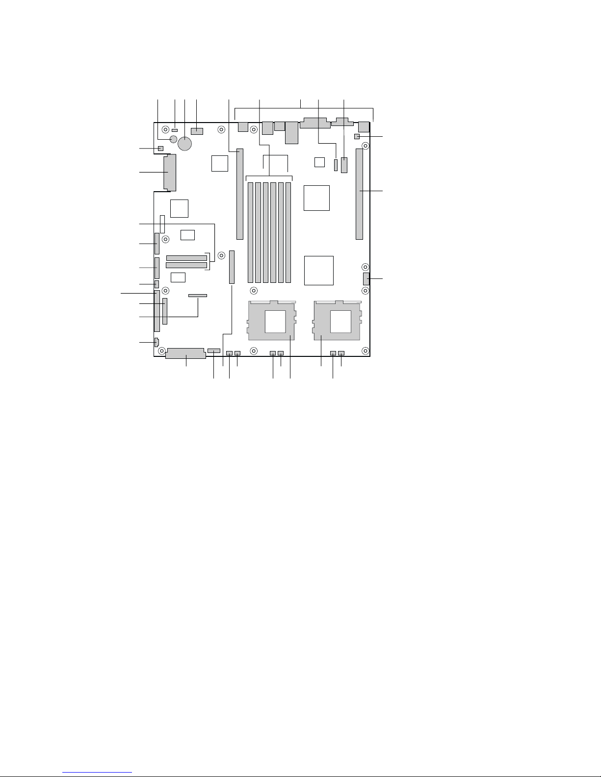
Server Board Components
A C D E
B
GG
FF
EE
DD
CC
BB
AA
Z
Y
X
SU
TV
A. Speaker
B. ID LED
C. Battery
D. Diagnostic LEDs (POST code)
E. 66 MHz/64-bit PCI riser slot (full height)
F. DIMM slots
G. I/O ports
H. ICMB connector
I. COM 1 serial header
J. Chassis intrusion connector
K. 66 MHz/64-bit PCI riser slot (low profile)
L. USB 3 & 4 header
M. Sys fan 3 connector
N. CPU 2 fan connector
O. Secondary processor socket
P. Primary processor socket
Q. Sys fan 2 connector
G
Q
R
R. CPU 1 fan connector
S. Sys fan 1 connector
T. Aux fan connector
U. Floppy drive connector
V. Fan module connector
W. Main power connector
X. Auxiliary signal connector
Y. Floppy/FP/IDE connector
Z. Alternate front panel connector
AA. ATA/IDE connector
BB. IPMB connector
CC. SSI front panel connector
DD. Configuration jumper block
EE. ATA-100 connectors
(ATA version only)
FF. SCSI connector
(SCSI version only)
GG. Hard Disk Drive LED header
IF H
OW M
NP
OM11707
J
K
L
Intel Server Board SCB2 Quick Start Guide 5
Page 6
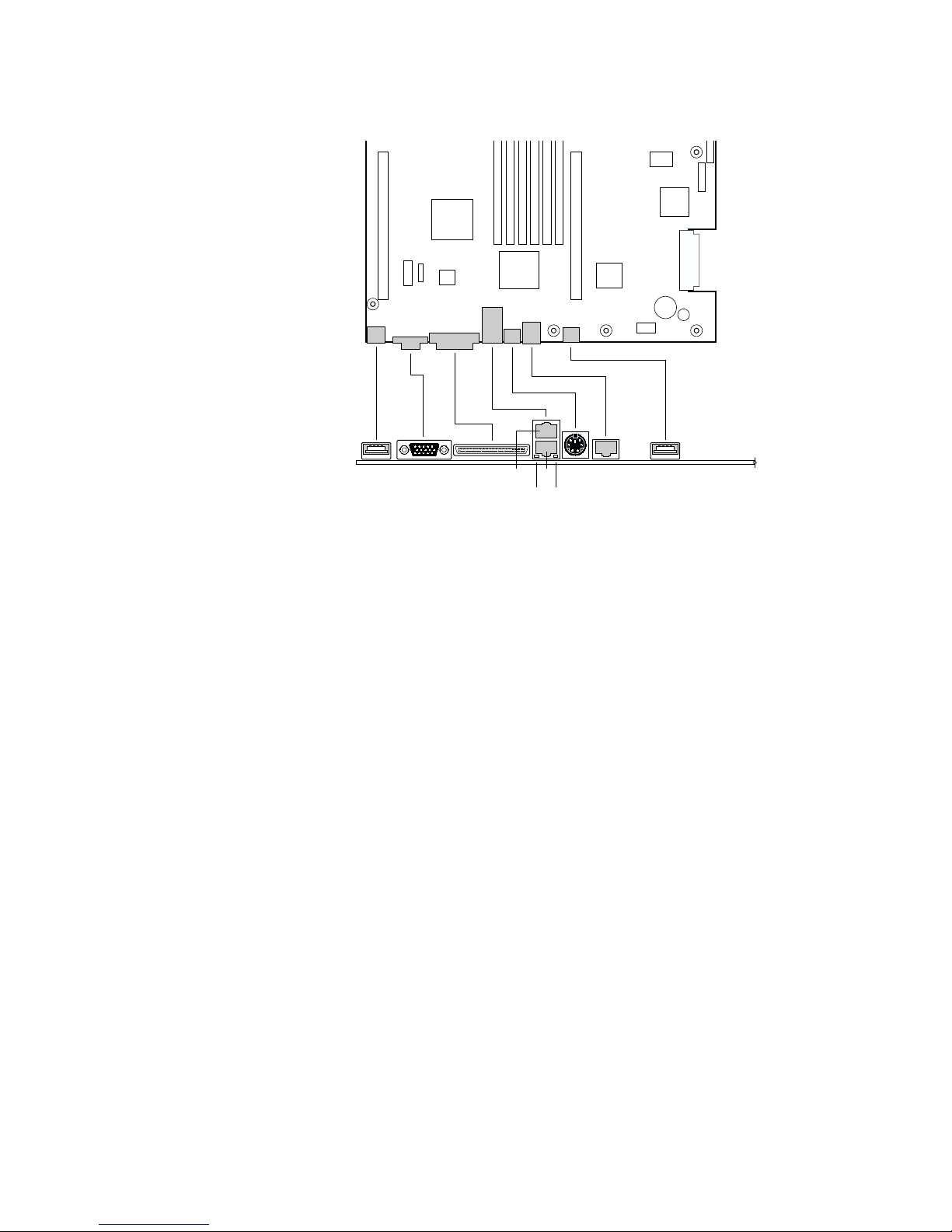
Back Panel Connectors
A
B
CJ
ED
H
I
F G
OM11713
A. USB 1 connector
B. Video connector
C. SCSI connector (SCSI server board only)
D. NIC 2 RJ-45 connector
E. NIC 1 RJ-45 connector
F. Green Status LED
G. Yellow Status LED
H. PS/2
I. RJ-45 serial port
J. USB 2 connector
†
keyboard/mouse connector
6 Intel Server Board SCB2 Quick Start Guide
Page 7
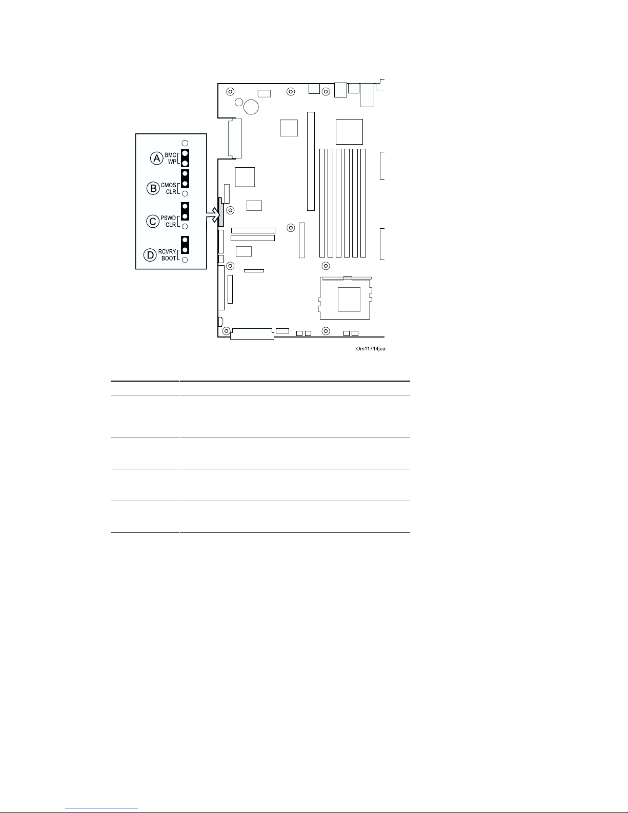
Jumpers
Configuration Jumper
Jumper Name Pins What it does at system reset
BMC WP A BMC boot block is write protected (normal
operation). If these pins are not jumpered, BMC
boot block is erasable and programmable at next
reset.
CMOS CLR B If these pins are jumpered, the CMOS settings are
cleared. These pins should not be jumpered for
normal operation.
PSWD CLR C If these pins are jumpered, the CMOS password is
cleared. These pins should not be jumpered for
normal operation.
RCVRY BOOT D If these pins are jumpered, the system will attempt
BIOS recovery. These pins should not be
jumpered for normal operation.
Intel Server Board SCB2 Quick Start Guide 7
Page 8
Installation Procedures
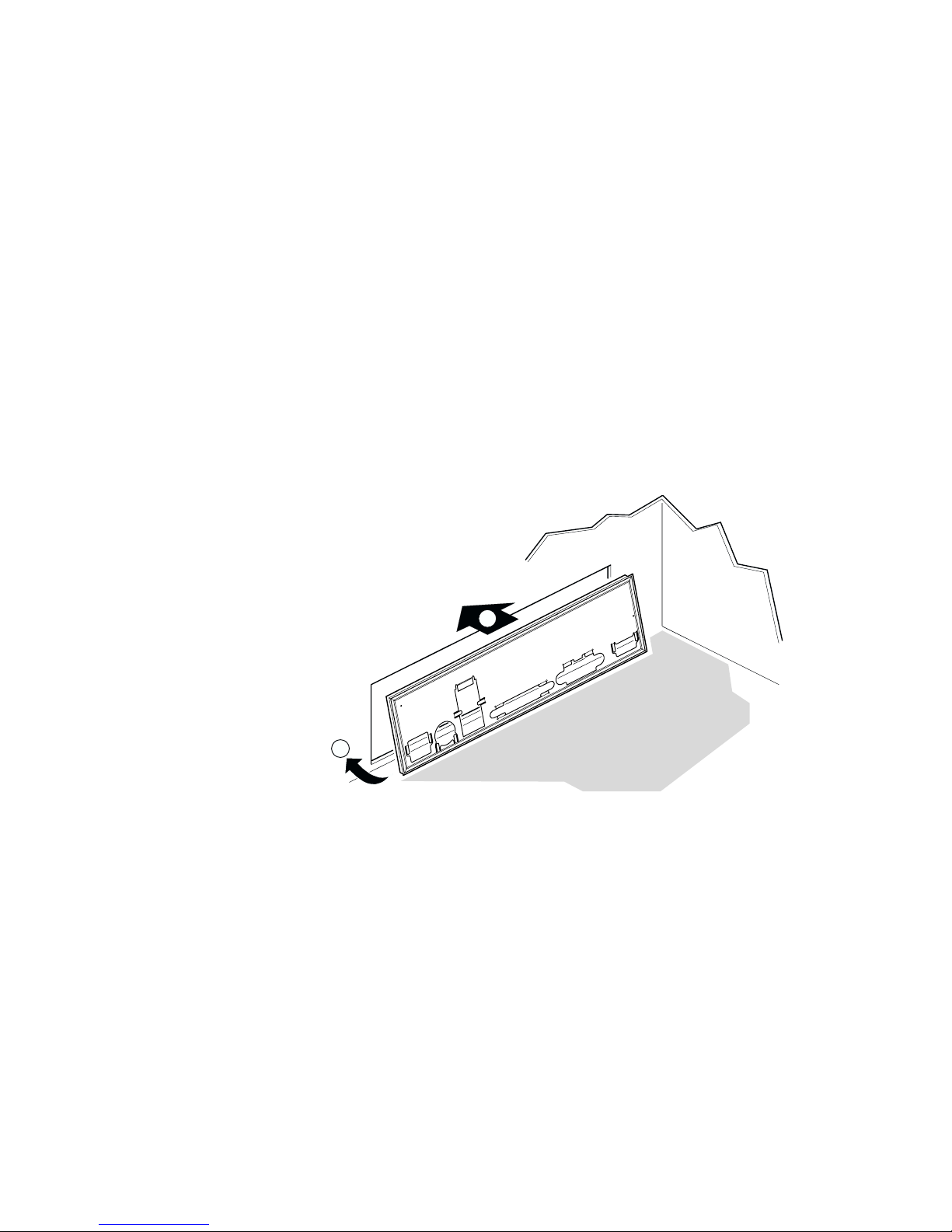
Install the I/O Shield
✏ NOTE
An ATX 2.03-compliant I/O shield is provided with the server board. The
shield is required by Electromagnetic Interference (EMI) regulations to
minimize EMI. If the shield does not fit the chassis, obtain a properly
sized shield from the chassis supplier. The I/O shield does not support
the use of the USB 2 connector.
The shield fits the rectangular opening in the back of a chassis. The shield has
cutouts that match the I/O ports.
1 Install the shield from inside the chassis. Orient the shield so that the
cutouts align with the corresponding I/O connectors on the server board.
Make sure the metal fingers are on the inside of the chassis.
2 Position one edge (A) so that the dotted groove is outside the chassis wall,
and the lip of the shield rests on the inner chassis wall.
3 Hold the shield in place, and push it into the opening (B) until it is seated.
Make sure the I/O shield snaps into place all the way around.
A
B
OM12162
8 Intel Server Board SCB2 Quick Start Guide
Page 9
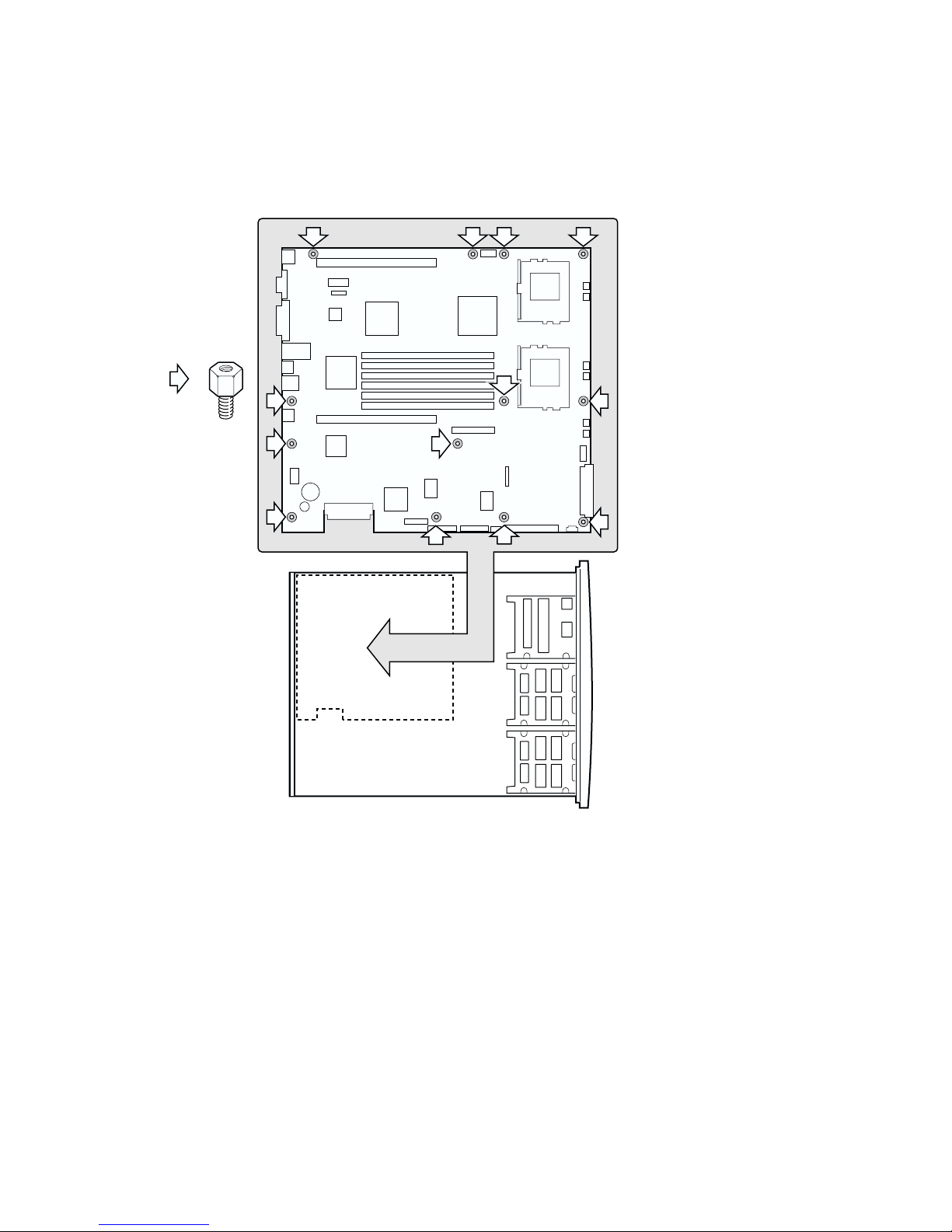
Rearrange the Standoffs
If your chassis does not have board mount standoffs placed as shown, you must
rearrange them so they match the holes in the server board. Failure to properly
rearrange the metal standoffs may cause the server board to malfunction and may
permanently damage it. Your chassis may be different from the illustration.
=
Intel Server Board SCB2 Quick Start Guide 9
OM11716B
Page 10
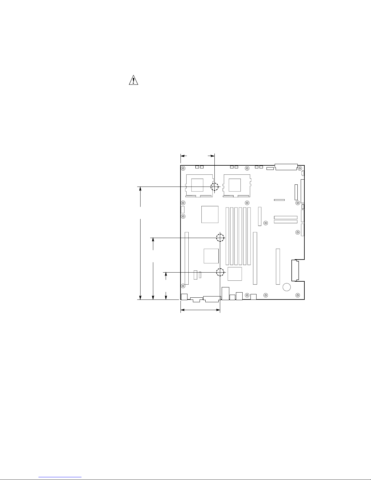
Server Board Bumpers
If you are installing your server board in a non-Intel chassis, you must provide
and install rubber bumpers at the locations shown below. They must be the same
height as the existing board mount standoffs.
CAUTIONS
You must install rubber bumpers in all nonIntel® chassis that do not
already support the board at the locations shown in the illustration.
The rubber bumpers you provide and install must be the same height as
the existing board mount standoffs to properly support your new board.
Failure to install bumpers, or installing bumpers that are too tall or too
short, may damage your board.
DO NOT INSTALL server board bumpers in the Intel
SR2200 server chassis.
3.6 inches
[85.0]
11.0 inches
[280.0]
®
SR1200 and
5.9 inches
[150.0]
2.7 inches
[70.0]
3.8 inches
[97.0]
OM12372
10 Intel Server Board SCB2 Quick Start Guide
Page 11
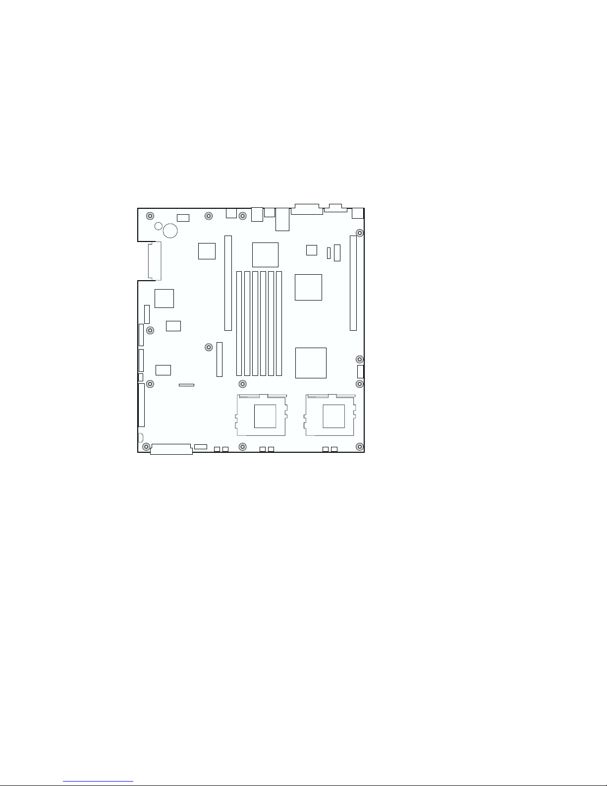
Install the Server Board
To ensure proper grounding and support, it is recommended that you install
screws in all the required mounting holes for your chassis. You may need to
move cables out of the way to properly install your server board.
1 While placing the board on the chassis standoffs, carefully position the
board I/O connectors into the rear chassis I/O openings.
2 Adjust board position to align mounting holes with standoffs.
3 Using the screws that came with your chassis, mount the board to the
chassis.
OM11716A
Intel Server Board SCB2 Quick Start Guide 11
Page 12

Installing Processors
1 Observe the safety and ESD precautions at the beginning of this document.
2 Raise the locking bar on the socket.
OM11711
12 Intel Server Board SCB2 Quick Start Guide
Page 13

3 Aligning the pins of the processor with the socket, insert the processor into
the socket.
4 Lower the locking bar completely.
OM11712
Intel Server Board SCB2 Quick Start Guide 13
Page 14

5 Following the instructions packaged with the applicator, apply thermal
grease to the processor.
6 Position the heat sink slot (2) above the socket/processor slot (3).
7 Aligning the raised metal surfaces, place the heat sink on top of the
processor.
8 Install the heat sink clip with pin (1) inserted into slot (2).
A
2
1
B
3
C
OM11708A
A. Heat sink retention clip
B. Heat sink
C. Socket and processor
14 Intel Server Board SCB2 Quick Start Guide
Page 15

CAUTION
Use care when closing the locking lever—do it slowly.
9 Slowly close the locking lever (A) until it contacts tab (B).
A
B
OM11709A
NOTE
If you are integrating a 1U chassis, do not install a fan on the processor
heat sink. If it is a 2U chassis, proceed to the next step.
10 Following the instructions provided with the processor, install the fan on
the processor heat sink.
11 Connect the fan to (A) if it is on the primary processor or to (B) if it is on
the secondary processor.
BA
CPU 1 Fan CPU 2 Fan
OM12163
Intel Server Board SCB2 Quick Start Guide 15
Page 16

Install the Processor Terminator
If you are installing only one processor, you must install a terminator in the
secondary processor socket (A). If you are installing two processors, skip this
section.
1 Raise the locking bar (B) on the socket.
2 Aligning the two corner marks on the terminator with the handle-side of the
socket (C), insert the terminator into the socket.
3 Lower the locking bar completely (D).
B
C
A
D
OM11710
16 Intel Server Board SCB2 Quick Start Guide
Page 17

Memory
Only PC133-compliant SDRAM is supported by the server board. Install from
128 MB to 6 GB of registered, ECC memory, using up to six DIMMs. A 1U
chassis requires low-profile (LP) 1.2-inch DIMMs.
DIMMs must be installed in pairs and in the following order: 1a and 1b, 2a and
2b, 3a and 3b.
Installed DIMMs must be the same speed and must all be registered. For a list
of supported memory, call your service representative or visit the Intel Support
website:
http://support.intel.com/support/motherboards/server
1A
3A1B2B
2A
3B
OM11715
Intel Server Board SCB2 Quick Start Guide 17
Page 18

Connect Cables
A
S
C
S
I
A
B
T
A
1
0
0
C
D
A
T
E
A
6
6
F
G
H
C
O
K
M
1
J
U
S
I
B
OM11717
Before connecting cables, consult the documentation supplied with your chassis.
A. SCSI connector (SCSI server board only)
B. ATA-100 primary/secondary connectors (ATA server board only)
C. SSI front panel connector (see the server board diagram label for pin out)
D. Front panel connector (For use in a non Intel chassis only)
E. IDE connector (For use in a non Intel chassis only)
F. Main power connector
G. Fan module connector (7-pin)
H. Fan connectors (system and processor)
I. USB header
J. Floppy connector (For use in a non Intel chassis only)
K. COM 1 header
L. Combined Floppy/Front Panel/IDE connector (For use in an
Intel chassis only)
Finish Setting up Your Chassis
You are now ready to install drives into your chassis. We recommend you
install drives before connecting their data cables to the server board.
18 Intel Server Board SCB2 Quick Start Guide
Page 19

Getting Help
World Wide Web
http://support.intel.com/support/motherboards/server/SCB2
Telephone
Talk to a Customer Support Technician*. Credit card calls billed at U.S. $25 per incident,
levied in local currency at the applicable credit card exchange rate plus applicable VAT.
(Intel reserves the right to change pricing for telephone support at any time without notice).
In U.S. and Canada: 1-800-404-2284
In Europe:
UK 0870 6072439
France 01 41 918529
Germany 069 9509 6099
Italy 02 696 33276
Spain 91 377 8166
In Asia-Pacific region:
Australia 1800 649931
Hong Kong 852 2 844 4456
Korea 822 767 2595
PRC 800 820 1100
Singapore 65 213-1311
Taiwan 2 2718 9915
India 0006517-2-830 3634
In Japan
0120-868686 (Domestic) 81-298-47-0800 (Out side country)
In Latin America
Brazil 0021-0811-408-5540
Mexico 001-800-6288686
Colombia 980-9-122-118
Costa Rica 0-800-011-0395
Panama 001-800-628-8686
Miami 1-800-621-8423
Finland 9 693 79297
Denmark 38 487077
Norway 23 1620 50
Sweden 08 445 1251
Holland 020 487 4562
Indonesia 803 65 7249
Malaysia 1-800 80 1390
New Zealand 0800 444 365
Pakistan 632 6368415
Philippines 1-800 1 651 0117
Thailand 1-800 6310003
Vietnam 632 6368416
Chile 800-532-992
Ecuador 999-119, 800-628-8686 (via AT&T)
Guatemala 99-99-190, 800-628-8686 (via AT&T)
Venezuela 800-11-120, 800-628-8686 (via AT&T)
Argentina 001-800-222-1001, 800-628-8686 (via AT&T)
Paraguay 008-11 800,628-8686 (via AT&T)
Peru 0-800-50288, 800-628-8686 (via AT&T)
Uruguay 000-410, 800-628-8686 (via AT&T)
*Or contact your local dealer or distributor.
For an updated support contact list, please see: http://www.intel.com/support/9089.htm
Technical Training & Support
If you are registered in the Intel Product Dealer Program (North America), the
Genuine Intel Dealer Program (Asia-Pacific Region), or the Intel Product
Integrator Program (Europe/Latin America), you are eligible for technical training
and support.
In U.S. and Canada: 1-800-538-3373, ext. 442 (M–F, 5:00 am–5:00 pm, PST)
In Europe: contact your distributor or fax your details to European Literature
on +44 (0) 1793 513142.
In Asia: +65-831-1379 (M–F, 8:30 am–5:30 pm, Singapore local time) or via
e-mail: APAC_gid@ccm.isin.intel.com
Intel Server Board SCB2 Quick Start Guide 19
Page 20

20 Intel Server Board SCB2 Quick Start Guide
Page 21

Intel® SCB2
............................................................................................2
............................................................................................4
......................................................................................4
..........................................................................5
..............................................................................6
..............................................................................................7
............................................................................................8
I/O ..........................................................................8
......................................................................9
.................................................................10
.........................................................................11
.................................................................................12
.....................................................................16
.............................................................................................17
.....................................................................................18
.............................................................................18
...........................................................................................19
Translations of this guide are available at:
Übersetzungen dieses Handbuchs sind erhältlich bei:
Versiones traducidas de esta guía se encuentran disponibles en:
Des traductions de ce guide sont disponibles à l'adresse:
Le versioni tradotte di questa Guida sono disponibili presso:
As traduções deste guia estão disponíveis em:
http://support.intel.com/support/motherboards/server/SCB2/manual.htm
Copyright © 2001, Intel Corporation. Intel
(Intel)
Intel
Intel
†
Intel Intel
Pentium Intel Corporation
Page 22

EMC EMC
SCB2
FCC A B B
(ESD)
Intel
(EMC) Intel®
ESD
2 Intel SCB2
Page 23

CD-ROM
Intel SCB2
®
SR1200 Server Chassis Subassembly Product Guide
Intel
Intel SR1200
®
SR2200 Server Chassis Subassembly Product Guide
Intel
Intel SR2200
Windows† 95/Windows NT† /
Windows 98 / Windows 2000
Adobe† Acrobat†
(EMC)
Intel SCB2
EMC
EMC
http://support.intel.com/support/motherboards/server/
FC-PGA2 Intel® Pentium® III
http://support.intel.com/support/motherboards/server/scb2
168 DIMM 128 MB 133 MHz 3.3 V
ECC PC/133 SDRAM
250W 0.8A +5V Wake On LAN† (WOL)
Intel SCB2 3
Page 24

I/O
•
•
1-3-3-1
DIMM
•
+5 V 0.8 A WOL
•
250 W
5
DIMM
4 Intel SCB2
Page 25

A C D E
GG
FF
EE
DD
CC
BB
AA
Z
Y
X
A.
B. ID LED
C.
D.
E. 66 MHz/64
F. DIMM
G. I/O
H. ICMB
I. COM 1
J.
K. 66 MHz/64
L. USB 3
M.
N. CPU 2
O.
P.
Q.
LED POST
4
3
2
B
TV
PCI
PCI
SU
G
Q
R
R. CPU 1
S.
T.
U.
V.
W.
X.
Y.
Z.
AA. ATA
BB. IPMB
CC. SSI
DD.
EE. ATA-100
FF. SCSI
GG.
(
IDE
SCSI )
IF H
OW M
NP
1
FP IDE
ATA
LED
J
K
L
OM11707
Intel SCB2 5
Page 26

A
B
CJ
ED
H
I
F G
OM11713
A. USB 1
B.
C. SCSI
D. NIC 2 RJ-45
E. NIC 1 RJ-45
F.
G.
H. PS/2
I. RJ-45
J. USB 2
LED
LED
†
SCSI
6 Intel SCB2
Page 27

BMC WP A BMC
BMC
CMOS CLR B CMOS
PSWD CLR C CMOS
RCVRY BOOT D BIOS
Intel SCB2 7
Page 28

I/O
✏
1
(EMI)
USB 2
ATX 2.03 I/O
EMI
I/O
I/O
I/O
2
3
B
(A)
(B) I/O
A
OM12162
8 Intel SCB2
Page 29

=
Intel SCB2 9
OM11716B
Page 30

Intel
11.0 inches
[280.0]
5.9 inches
[150.0]
®
Intel
Intel® SR1200 SR2200
3.6 inches
[85.0]
2.7 inches
[70.0]
3.8 inches
[97.0]
OM12372
10 Intel SCB2
Page 31

1
I/O
2
3
OM11716A
Intel SCB2 11
Page 32

1
ESD
2
OM11711
12 Intel SCB2
Page 33

3
4
OM11712
Intel SCB2 13
Page 34

5
6
7
8
(2) (3)
(1) (2)
A
2
1
B
3
C
OM11708A
A.
B.
C.
14 Intel SCB2
Page 35

9 (A) (B)
A
B
OM11709A
1U
2U
10
11
(A)
(B)
BA
CPU 1 Fan CPU 2 Fan
OM12163
Intel SCB2 15
Page 36

(A)
1
(B)
2
(C)
3
(D)
B
C
A
D
OM11710
16 Intel SCB2
Page 37

PC133 SDRAM
ECC DIMM 128 MB 6 GB 1U
(LP) 1.2 DIMM
DIMM
2b
3a 3b
DIMM
Intel
http://support.intel.com/support/motherboards/server
1A
3A1B2B
2A
3B
1a 1b 2a
OM11715
Intel SCB2 17
Page 38

A
S
C
S
I
A
B
T
A
1
0
0
C
D
A
T
E
A
6
6
F
G
A. SCSI SCSI
B. ATA-100
C. SSI
D.
E. IDE
F.
G.
H.
I. USB
J.
K. COM 1
L.
/ ATA
Intel
Intel
7
Intel
IDE Intel
C
O
K
M
1
J
U
S
I
B
H
OM11717
18 Intel SCB2
Page 39

http://support.intel.com/support/motherboards/server/SCB2
* 25
Intel
0870 6072439
01 41 918529
069 9509 6099
02 696 33276
91 377 8166
1800 649931
852 2 844 4456
822 767 2595
800 820 1100
65 213-1311
2 2718 9915
0006517-2-830 3634
0120-868686
0021-0811-408-5540
001-800-6288686
980-9-122-118
0-800-011-0395
001-800-628-8686
1-800-621-8423
1-800-404-2284
9 693 79297
38 487077
23 1620 50
08 445 1251
020 487 4562
803 65 7249
1-800 80 1390
0800 444 365
632 6368415
1-800 1 651 0117
1-800 6310003
632 6368416
81-298-47-0800
800-532-992
999-119, 800-628-8686 AT&T
99-99-190, 800-628-8686 AT&T
800-11-120, 800-628-8686 AT&T
001-800-222-1001, 800-628-8686 AT&T
008-11 800,628-8686 AT&T
0-800-50288, 800-628-8686 AT&T
000-410, 800-628-8686 AT&T
*
http://www.intel.com/support/9089.htm
Intel
+65-831-1379 8:30
5:30
APAC_gid@ccm.isin.intel.com
Intel SCB2 19
Page 40

20 Intel SCB2
 Loading...