

Page 1

Intel® Server Chassis SC5650-DP/WS/BRP/UP
Service Guide
A Guide for Technically Qualified Assemblers of Intel® Identified Subassemblies/Products
Intel Order Number E55434-003
Page 2

Disclaimer
®
Information in this document is provided in connection with Intel
products. No license, expre ss or implied, by
estoppel or otherwise, to any intellectual property rights is granted by this document. Except as provided in Intel's
Terms and Conditions of Sale for such products, Intel assumes no liability whatsoever, and Intel disclaims any
express or implied warranty, relating to sale and/or use of Intel
®
products including liability or warranties relating to
fitness for a particular purpose, merchantability, or infringement of any patent, copyright or other intellectual property
right. Intel products are not designed, intended or authorized for use in any medical, life saving, or life sustaining
applications or for any other application in which the failure of the Intel product could create a situation where
personal injury or death may occur. Intel may make changes to specifications and product descriptions at any time,
without notice.
l®
server boards contain a number of high-density VLSI and power delivery components that need adequate
Inte
airflow for cooling. Intel's own chassis are designed and tested to meet the intended thermal requirements of these
components when the fully integrated system is used together . It is the responsibility of the system integrator that
chooses not to use Intel developed server building blocks to consult vendor datasheets and operating parameters to
determine the amount of airflow required for their specific application and environmental conditions. Intel Corporation
can not be held responsible if components fail or the server board does not operate correctly when used outside any
of their published operating or non-operating limits.
Intel, Intel Pentium, and Intel Xeon are trademarks or registered trademarks of Intel Corporation or its subsidiaries in
the United States and other countries.
* Other names and brands may be claimed as the property of others.
Copyright © 2009, Intel Corporation. All Rights Reserved
ii Intel® Server Chassis SC5650-DP/WS/BRP/UP Service Guide
Page 3

Safety Information
䞡㽕ᅝܼᣛᇐ
ᠻ㸠ӏԩᣛҸПࠡˈ䇋䯙䇏ᴀ᭛ḷЁⱘ᠔᳝⊼ᛣџ乍ঞᅝܼໄᯢDŽ
http://support.intel.com/support/motherboards/server/sb/CS -010770.htmϞⱘ,QWHO
6HUYHU%RDUGVDQG6HUYHU&KDVVLV6DIHW\,QIRUPDWLRQ˄lj,QWHO
᳡ࡵ఼ЏᵓϢ᳡ࡵ఼ᴎㆅᅝֵܼᙃNJ˅DŽ
Important Safety Instructions
Read all caution and safety statements in this document before performing any of the
instructions. See also Intel Server Boards and Server Chassis Safety Information on the
®
Server Deployment Toolkit CD and/or at http://support.intel.com/support/
Intel
motherboards/server/sb/cs-010770.htm.
Wichtige Sicherheitshinweise
Lesen Sie zunächst sämtliche Warnund Sicherheitshinweise in diesem Dokument, bevor
Sie eine der Anweisungen ausführen. Beachten Sie hierzu auch die Sicherheitshinweise zu
Intel-Serverplatinen und Servergehäusen auf der Intel
oder unter http://support.intel.com/support/motherboards/server/sb/cs-010770.htm.
Consignes de sécurité
®
Server Deployment Toolkit CD
Lisez attention toutes les consignes de sécurité et les mises en garde indiquées dans ce
document avant de suivre toute instruction. Consultez Intel Server Boards and Server
Chassis Safety Information sur le Intel
vous sur le site http://support.intel.com/support/motherboards/server/sb/cs-010770.htm.
®
Server Deployment Toolkit CD ou bien rendez-
Instrucciones de seguridad importantes
Lea todas las declaraciones de seguridad y precaución de este documento antes de realizar
cualquiera de las instrucciones. Vea Intel Server Boards and Server Chassis Safety
Information en el Intel
support/motherboards/server/sb/cs-010770.htm.
®
Server Deployment Toolkit CD y/o en http://support.intel.com/
Intel® Server Chassis SC5650-DP/WS/BRP/UP Service Guide iii
Page 4

Safety Information
Warnings
Heed safety instructions: Before working with your server product, whether you are
using this guide or any other resource as a reference, pay close attention to the safety
instructions. You must adhere to the assembly instructions in this guide to ensure and
maintain compliance with existing product certifications and approvals. Use only the
described, regulated components specified in this guide. Use of other products /
components will void the UL listing and other regulatory approvals of the product and
will most likely result in noncompliance with product regulations in the region(s) in which
the product is sold.
System power on/off: The power button DOES NOT turn off the system AC power. To
remove power from system, you must unplug the AC power cord from the wall outlet.
Make sure the AC power cord is unplugged before you open the chassis, add, or remove
any components.
Hazardous conditions, devices and cables: Hazardous electrical conditions may be
present on power, telephone, and communication cables. Turn off the server and
disconnect the power cord, telecommunications systems, networks, and modems attached
to the server before opening it. Otherwise, personal injury or equipment damage can
result.
Electrostatic discharge (ESD) and ESD protection: ESD can damage disk drives,
boards, and other parts. We recommend that you perform all procedures in this chapter
only at an ESD workstation. If one is not available, provide some ESD protection by
wearing an antistatic wrist strap attached to chassis ground any unpainted metal surface on
your server when handling parts.
ESD and handling boards: Always handle boards carefully. They can be extremely
sensitive to ESD. Hold boards only by their edges. After removing a board from its
protective wrapper or from the server, place the board component side up on a grounded,
static free surface. Use a conductive foam pad if available but not the board wrapper. Do
not slide board over any surface.
Installing or removing jumpers: A jumper is a small plastic encased conductor that slips
over two jumper pins. Some jumpers have a small tab on top that you can grip with your
fingertips or with a pair of fine needle nosed pliers. If your jumpers do not have such a tab,
take care when using needle nosed pliers to remove or install a jumper; grip the narrow
sides of the jumper with the pliers, never the wide sides. Gripping the wide sides can
damage the contacts inside the jumper, causing intermittent problems with the function
controlled by that jumper. Take care to grip with, but not squeeze, the pliers or other tool
you use to remove a jumper, or you may bend or break the pins on the board.
iv Intel® Server Chassis SC5650-DP/WS/BRP/UP Service Guide
Page 5

Preface
About this Manual
Thank you for purchasing and using the Intel® Server Chassis SC5650.
This manual is written for system technicians responsible for troubleshooting, upgrading,
and repairing this server chassis. This document provides a brief overview of the features
of the chassis, a list of accessories or other components you may need, troubleshooting
information, and instructions on how to add and replace components on the Intel
Chassis SC5650. For the latest version of this manual, see: http://support.intel.com/
support/motherboards/server/chassis/sc5650/.
Manual Organization
Chapter 1 provides a brief overview of the Intel® Server Chassis SC5650. In this chapter,
you will find a list of the server chassis features, photos of the product, and product
diagrams to help you identify components and their locations.
Chapter 2 provides instructions on adding and replacing components. Use this chapte r for
step-by-step instructions and diagrams for installing or replacing components such as the
fans, power supply, drives, and other components.
®
Server
At the back of this book, you will find technical specifications, regulatory information,
"getting help" information, and the warranty.
Product Contents, Order Options, and Accessories
This server chassis is compatible with the following Intel® Server Boards:
• Intel
• Intel
• Intel
• Intel
• Intel
Your Intel
• A power factor correction (PFC) power supply, installed in the chassis. Power supply
• A box of hardware components, referred to as the "hardware kit"
®
Server Board S5500BC
®
Server Board S5520HC
®
Server Board S5500HCV
®
Server Board S5520SC
®
Server Board S3420GP Family
®
Server Chassis SC5650 ships with the following items:
wattage depends on the model of server chassis you purchased. Three power supply
configurations are available.
Intel® Server Chassis SC5650-DP/WS/BRP/UP Service Guide v
Page 6

Preface
• Fan cable, installed in the chassis
• Chassis intrusion switch, installed in the chassis
• Front panel, installed in the chassis
• Attention document, in the chassis product box
• Intel
®
Server Chassis SC5650 Quick Start User's Guide, in the chassis product box
• Four M3 screws for installing 5.25-in drive component, in the hardware kit
• Fifteen 6-32 screws for mounting the server board to the chassis, in the hardware kit
• USB cable
In addition, you may need or want to purchase one or more of the following accessory
items for your server:
• Processor, memory DIMMs, Server Motherboard
• Hard drive
• CD-ROM or DVD-ROM drive
• RAID controller
• Operating system
For information about which accessories, memory, processors, and third-party hardware
were tested and can be used with your server board, and for ordering information for
®
products, see: http://support.intel.com/support/motherboards/server/chassis/
Intel
sc5650/compat.htm
Additional Information and Software
If you need more information about this product or information about the accessories that
can be used with this server chassis, use the following resources. These files are available
at: http://support.intel.com/support/motherboards/server/chassis/sc5650/
Unless otherwise indicated in the following table, once on this Web page, type the
document or software name in the search field at the left side of the screen and select the
option to search "This Product."
For this information or
software
For in-depth technical
information about this
product, including
dimensions and power
characteristics
If you just received this
product and need to install
it
®
Intel
Server Chassis SC5650 Technical Product Specification
http://support.intel.com/support/motherboards/server/chassis/
sc5650
®
Intel
Server Chassis SC5650 Quick Start User's Guide in the
product box
Use this Document or Software
vi Intel® Server Chassis SC5650-DP/WS/BRP/UP Service Guide
Page 7

Preface
For this information or
software
For virtual system tours
and interactive repair
information
Accessories or other Intel
server products
Hardware (peripheral
boards, adapter cards, and
so forth) and operating
systems that were tested
with this product
To make sure your system
falls within the allowed
power budget
For software to manage
your Intel
®
server
Use this Document or Software
®
A link to the Intel
Server Configurator tool is available under "Other
Resources" at the right side of the screen at:
http://support.intel.com/support/motherboards/server/chassis/
sc5650
Spares and Configuration Guide
http://support.intel.com/support/motherboards/server/chassis/
sc5650
Tested Hardware/Operating Systems List
http://support.intel.com/support/motherboards/server/chassis/
sc5650
Power Budget Tool at:
http://support.intel.com/support/motherboards/server/s5500BC
®
System Management Software
Intel
Intel® Server Chassis SC5650-DP/WS/BRP/UP Service Guide vii
Page 8

Preface
viii Intel® Server Chassis SC5650-DP/WS/BRP/UP Service Guide
Page 9

Contents
Safety Information ..................................................................................................... iii
Important Safety Instructions ................................................................................................ iii
Wichtige Sicherheitshinweise ............................................................................................... iii
Consignes de sécurité .......................................................................................................... iii
Instrucciones de seguridad importantes ............................................................................... iii
Warnings ............................................................................................................................... iv
Preface .........................................................................................................................v
About this Manual ..................................................................................................................v
Manual Organization ........................................................................................................... ...v
Product Contents, Order Options, and Accessories ..............................................................v
Additional Information and Software .....................................................................................vi
Server Chassis Features ............................................................................................1
Component Identification .......................................................................................................3
Front View Components .............................................................................................. ..3
Internal Components .....................................................................................................5
Back Panel Components ...............................................................................................6
Front Panel ....................................................................................................................7
Peripheral Devices .................................................................................................................8
Hard Disk Drives ............................................................................................................9
Front Bezel Assembly ..........................................................................................................10
Rack-Mounted Systems .......................................................................................................10
Mechanical Locks ................................................................................................................11
Accessories and Order Codes .............................................................................................11
Hardware Installations and Upgrades ....................................................................13
Before You Begin .................................................................................................................13
Tools and Supplies Needed ........................................................................................13
System References .....................................................................................................13
Removing and Installing the Left Side Cover ....................................................................... 13
Removing the Left Side Cover .....................................................................................13
Installing the Left Side Cover .......................................................................................14
Removing and Installing the Right Side Cover ....................................................................15
Removing the Right Side Cover ..................................................................................15
Installing the Right Side Cover ....................................................................................16
Removing and Installing the Front Bezel Assembly ............................................................17
Removing the Front Bezel Assembly ..........................................................................17
Installing the Front Bezel Assembly ............................................................................18
Installing or Removing a Server Board ................................................................................18
Installing and Removing a Fixed Hard Drive .......................................................................24
Installing a Fixed Hard Drive .......................................................................................24
Removing a Fixed Hard Drive .....................................................................................30
Installing or Removing a DVD-ROM or CD-ROM Drive .......................................................33
Installing a DVD-ROM or CD-ROM Drive ....................................................................33
Intel® Server Chassis SC5650-DP/WS/BRP/UP Service Guide ix
Page 10

Removing a CD-ROM or DVD-ROM Drive .................................................................35
Installing and Removing PCI Add-in Boards ....................................................................... 36
Installing PCI Add-in Boards .......................................................................................36
Removing PCI Add-in Boards .....................................................................................38
Replacing the Front Panel Board ........................................................................................40
Replacing a System Fan .....................................................................................................44
Replacing a Fixed Power Supply ........................................................................................48
Installing an Additional Hot Swap Power Supply Module (BRP configuration only) ............ 51
Removing a Hot Swap Power Supply (BRP configuration only) ......................................... 52
Replacing a Hot Swap Power Supply Cage (BRP configuration only) ................................53
Installing Feet for a Pedestal-configured Chassis ............................................................... 59
Hot Swap Drive Cage Upgrade Install Instructions (optional) ..............................61
Before You Begin ................................................................................................................61
Kits Required ...............................................................................................................61
Tools and Supplies Needed ........................................................................................61
System References .....................................................................................................61
Installing a Hot Swap Hard Drive Cage with a SAS/SATA Backplane ................................62
Installing a Hot Swap Hard Drive ........................................................................................75
Removing a Hot-swap Hard Drive ...............................................................................78
Rack Mount Kit Install Instructions (optional) .......................................................83
Before You Begin ................................................................................................................83
Tools and Supplies Needed ........................................................................................83
System References .....................................................................................................83
Setting up a Rack-configured Chassis ................................................................................83
Technical Reference .................................................................................................95
Cable Routing ......................................................................................................................95
Power Supply Specifications ...............................................................................................95
DP 600-W Power Supply Input Voltages ....................................................................95
DP 600-W Power Supply Output Voltages ..................................................................95
600-W Single Power Supply Input Voltages ...............................................................96
600-W Single Power Supply Output Current ...............................................................96
1000-W Single Power Supply Input Voltages .............................................................96
1000-W Single Power Supply Output Voltages ...........................................................96
DP 400-W Power Supply Input Voltages ....................................................................96
DP 400-W Power Supply Output Voltages ..................................................................97
System Environmental Specifications ................................................................................. 97
A. Safety Information ................................................................................................99
English ................................................................................................................................. 99
Server Safety Information ...........................................................................................99
Safety Warnings and Cautions ....................................................................................99
Intended Application Uses ........................................................................................100
Site Selection ............................................................................................................100
Equipment Handling Practices .................................................................................. 100
Power and Electrical Warnings .................................................................................101
Access Warnings ......................................................................................................101
Electrostatic Discharge (ESD) ...................................................................................102
Other Hazards ...........................................................................................................102
Deutsch ............................................................................................................................. 103
x Intel® Server Chassis SC5650-DP/WS/BRP/UP Service Guide
Page 11

Sicherheitshinweise für den Server ...........................................................................103
Sicherheitshinweise und Vorsichtsmaßnahmen ........................................................103
Zielbenutzer der Anwendung .....................................................................................104
Standortauswahl ........................................................................................................104
Handhabung von Geräten .........................................................................................105
Warnungen zu Netzspannung und Elektrizität ..........................................................106
Warnhinweise für den Systemzugang .......................................................................106
Elektrostatische Entladungen (ESD) .........................................................................107
Andere Gefahren .......................................................................................................108
Français .............................................................................................................................109
Consignes de sécurité sur le serveur ........................................................................109
Sécurité: avertissements et mises en garde ..............................................................109
Domaines d’utilisation prévus ....................................................................................110
Sélection d’un emplacement .....................................................................................110
Pratiques de manipulation de l’équipement ...............................................................110
Alimentation et avertissements en matière d’électricité .............................................111
Avertissements sur l’accès au système .....................................................................111
Décharges électrostatiques (ESD) ............................................................................112
Autres risques ............................................................................................................112
Español ..............................................................................................................................113
Información de seguridad del servidor ......................................................................113
Advertencias y precauciones sobre seguridad ..........................................................113
Aplicaciones y usos previstos .................................................................................... 114
Selección de la ubicación ..........................................................................................114
Manipulación del equipo ............................................................................................115
Advertencias de alimentación y eléctricas .................................................................115
Advertencias el acceso al sistema ............................................................................116
Descarga electrostática (ESD) ..................................................................................117
Otros peligros ............................................................................................................117
B. Installation/Assembly Safety Instructions .......................................................125
English ...............................................................................................................................125
Deutsch ..............................................................................................................................127
Français .............................................................................................................................129
Español ..............................................................................................................................131
Italiano ...............................................................................................................................133
C. Getting Help ........................................................................................................137
Getting Help .......................................................................................................................137
Warranty Information .........................................................................................................137
D. Intel® Server Chassis Issue Report Form ........................................................ 139
E. Warranty ..............................................................................................................143
Limited Warranty for Intel® Chassis Subassembly Products .............................................143
Extent of Limited Warranty ................................................................................................143
Warranty Limitations and Exclusions .................................................................................144
Limitations of Liability ................................................................................................144
How to Obtain Warranty Service .......................................................................................144
Telephone Support ....................................................................................................145
Returning a Defective Product ...................................................................................145
F. Regulatory and Compliance Information .........................................................147
Intel® Server Chassis SC5650-DP/WS/BRP/UP Service Guide xi
Page 12

Product Regulatory Compliance ........................................................................................147
Product Safety Compliance .......................................................................................147
Product EMC Compliance - Class A Compliance ..................................................... 148
Certifications / Registrations / Declarations ..............................................................149
Product Regulatory Compliance Markings ................................................................ 149
FCC Verification Statement (USA) ............................................................................ 152
Industry Canada (ICES-003) ..................................................................................... 153
Europe (CE Declaration of Conformity) .....................................................................153
VCCI (Japan) ............................................................................................................153
BSMI (Taiwan) ..........................................................................................................153
Korean Compliance (RRL) ........................................................................................ 154
CNCA (CCC-China) .................................................................................................. 154
Regulated Specified Components .............................................................................154
Restriction of Hazardous Substances (RoHS) Compliance .............................................. 155
End-of-Life / Product Recycling .........................................................................................155
xii Intel® Server Chassis SC5650-DP/WS/BRP/UP Service Guide
Page 13

List of Figures
Figure 1. Front View of Intel® Server Chassis SC5650..............................................................1
Figure 2. Front View Components (with Front Bezel Assembly)................................................3
Figure 3. Front View Components (without Front Bezel Assembly)...........................................4
Figure 4. Internal Components (DP/WS/BRP Configuration Shown).........................................5
Figure 5. Back Panel Components.............................................................................................7
Figure 6. Front Panel Components............................................................................................8
Figure 7. Optional Peripheral Devices (DP/WS/BRP configuration shown)...............................9
Figure 8. Mechanical Locks......................................................................................................11
Figure 9. Removing Left Side Cover........................................................................................14
Figure 10. Installing Left Side Cover........................................................................................14
Figure 11. Removing Right Side Cover from Chassis..............................................................15
Figure 12. Re-installing Right Side Cover on Chassis.............................................................16
Figure 13. Removing Front Bezel Assembly (DP/WS/BRP configuration shown)................... 17
Figure 14. Installing the Front Bezel Assembly (DP/WS/BRP configuration shown) ...............18
Figure 15. Removing Drive Cage EMI Shield from Fixed Drive Cage (DP/WS/BRP configur ation
shown)................................................................................................................................ 19
Figure 16. Removing Fixed Hard Drive Cage (DP/WS/BRP configuration shown)..................20
Figure 17. Removing PCI Card Guide......................................................................................20
Figure 18. Re-installing PCI Card Guide into Chassis.............................................................21
Figure 19. Inserting Fixed Hard Drive Cage into Chassis (DP/WS/BRP configuration only)... 22
Figure 20. Re-attaching Drive Cage EMI Shield......................................................................23
Figure 21. Drive Bay Slot Order...............................................................................................24
Figure 22. Removing Drive Cage EMI Shield from Chassis (DP/WS/BRP configuration shown)
25
Figure 23. Removing PCI Card Guide......................................................................................26
Figure 24. Routing Hard Drive Power Cables..........................................................................26
Figure 25. Unlatching Drive Latch............................................................................................27
Figure 26. Inserting Hard Drive into Drive Cage......................................................................27
Figure 27. Latching Drive Latch ...............................................................................................28
Figure 28. Drive Bay Slot Order...............................................................................................28
Figure 29. Cabling a Fixed Hard Drive.....................................................................................29
Figure 30. Re-installing Drive Cage EMI Shield.......................................................................29
Figure 31. Re-installing PCI Card Guide..................................................................................30
Figure 32. Removing Drive Cage EMI Shield from Chassis (DP/WS/BRP configuration shown)
31
Figure 33. Preparing Fixed Hard Drive for Removal................................................................31
Figure 34. Removing Fixed Hard Drive from Drive Bay...........................................................32
Figure 35. Re-installing Drive Cage EMI Shield.......................................................................32
Figure 36. Removing 5.25-in Drive EMI Shield (DP/WS/BRP configuration shown)................33
Figure 37. Installing CD-ROM or DVD-ROM Drive (DP/WS/BRP configuration shown).......... 34
Figure 38. Removing CD-ROM or DVD-ROM Drive (DP/WS/BRP configuration shown)........35
Figure 39. Installing 5.25-in Drive EMI Shield (DP/WS/BRP configuration shown)..................36
Intel® Server Chassis SC5650-DP/WS/BRP/UP Service Guide xiii
Page 14

Figure 40. Opening PCI Add-in Card Retention Device (DP/WS/BRP configuration shown).. 37
Figure 41. Removing PCI Slot Shield ...................................................................................... 37
Figure 42. Installing PCI Add-in Board..................................................................................... 38
Figure 43. Opening PCI Add-in Card Retention Device (DP/WS/BRP configuration shown).. 39
Figure 44. Removing PCI Add-in Board................................................................................... 39
Figure 45. Replacing PCI Slot Shield....................................................................................... 40
Figure 46. Removing Right Side Cover from Chassis ............................................................. 41
Figure 47. Unattaching Front Panel Board from Chassis........................................................ 41
Figure 48. Removing Front Panel Board from Chassis........................................................... 42
Figure 49. Removing Standoffs from Front Panel.................................................................... 42
Figure 50. Installing Front Panel Board in Chassis.................................................................. 43
Figure 51. Positioning Front Panel Board in Chassis .............................................................. 43
Figure 52. Re-installing Right Side Cover on Chassis............................................................. 44
Figure 53. Removing Fan Duct / System Fan Assembly (DP/WS/BRP configuration)............ 45
Figure 54. Removing System Fan from Chassis ..................................................................... 45
Figure 55. Removing Fan Duct / System Fan Assembly (UP configuration)........................... 46
Figure 56. Installing System Fan in Chassis............................................................................ 46
Figure 57. Re-installing Fan Duct / System Fan Assembly (DP/WS/BRP configuration) ........ 47
Figure 58. Re-installing Fan Duct / System Fan Assembly (UP configuration)........................ 47
Figure 59. Unlocking Fixed Power Supply from Chassis......................................................... 48
Figure 60. Removing Fixed Power Supply from Chassis......................................................... 49
Figure 61. Inserting Fixed Power Supply in Chassis ............................................................... 49
Figure 62. Locking Fixed Power Supply into Chassis.............................................................. 50
Figure 63. Removing Power Supply Filler Panel ..................................................................... 51
Figure 64. Inserting Additional Hot Swap Power Supply Module............................................. 51
Figure 65. Removing Hot Swap Power Supply Module from Chassis..................................... 52
Figure 66. Inserting Hot Swap Power Supply Module in Chassis............................................ 53
Figure 67. Removing Hot Swap Power Supply Module........................................................... 54
Figure 68. Detaching Hot Swap Power Supply Cage from Inside of Chassis.......................... 54
Figure 69. Detaching Hot Swap Power Supply Cage from Rear of Chassis........................... 55
Figure 70. Removing Rear Support Bracket from Hot Swap Power Supply Cage.................. 55
Figure 71. Attaching Rear Support Bracket to Power Supply Cage........................................ 56
Figure 72. Securing Hot Swap Power Supply Cage to Rear of Chassis.................................. 56
Figure 73. Securing Hot Swap Power Supply Cage to Inside of Chassis................................ 57
Figure 74. Re-installing Hot Swap Power Supply Module(s)................................................... 58
Figure 75. Installing Feet on Chassis....................................................................................... 59
Figure 76. Removing Fixed Drive Cage EMI Shield from Chassis (DP/WS/BRP configuration
shown) ............................................................................................................................... 62
Figure 77. Removing Fixed Hard Drive Cage from Chassis (DP/WS/BRP configuration shown)
63
Figure 78. Removing Stud Screws from Hot Swap Drive Cage............................................... 64
Figure 79. Attaching Latch Plate to Hot Swap Drive Cage...................................................... 64
Figure 80. Attaching Filler Panel to Hot Swap Drive Cage...................................................... 65
Figure 81. Removing Thumb Screws from Backplane............................................................. 65
Figure 82. Attaching Fan Bracket to Expanded Hot Swap Drive Cage.................................... 66
Figure 83. Attaching Fan Bracket to Non-Expanded Hot Swap Drive Cage............................ 67
Figure 84. Attaching Fan to Fan Bracket................................................................................. 68
xiv Intel® Server Chassis SC5650-DP/WS/BRP/UP Service Guide
Page 15

Figure 85. Attaching Fan to Fan Bracket Non-Expanded, Hot Swap Drive Cage....................69
Figure 86. Inserting Hot Swap Drive Cage into Chassis (DP/WS/BRP configuration shown)..70
Figure 87. Layout of Cable Connectors on the SAS/SATA Backplane (Backplane without ex-
pander shown)....................................................................................................................72
Figure 88. Making Six-drive SAS/SATA Hot-Swap Drive Cage Backplane without Expander
Connections (DP/WS/BRP configuration shown - fan bracket not shown in the illustration for
clarity).................................................................................................................................73
Figure 89. Making Six-drive Hot Swap Drive Cage Backplane with Expander Connections (DP/
WS/BRP configuration shown - fan bracket not shown in the illustration for clarity).......... 74
Figure 90. Opening Drive Bay Access Door.............................................................................75
Figure 91. Releasing Drive Carrier from Hot Swap Drive Cage...............................................76
Figure 92. Removing Retention Device from Drive Carrier......................................................76
Figure 93. Installing Hard Drive into Drive Carrier....................................................................77
Figure 94. Re-installing Drive Carrier in Hot Swap Drive Cage................................................77
Figure 95. Closing Drive Bay Access Door..............................................................................78
Figure 96. Opening Drive Bay Access Door.............................................................................78
Figure 97. Removing Drive Carrier from Hot Swap Drive Cage...............................................79
Figure 98. Removing Hard Drive from Drive Carrier................................................................79
Figure 99. Installing Hard Drive in Drive Carrier.......................................................................80
Figure 100. Installing Plastic Retention Device in Drive Carrier...............................................80
Figure 101. Re-installing Drive Carrier in Hot Swap Drive Cage..............................................81
Figure 102. Closing Drive Bay Access Door............................................................................81
Figure 103. Removing Chassis Feet........................................................................................84
Figure 104. Removing Top Side Cover from Chassis..............................................................84
Figure 105. Removing PCI Card Guide.................................................................................... 85
Figure 106. Removing Plastic Filler Panel from Chassis (DP/WS/BRP configuration shown).86
Figure 107. Removing Plastic Plugs (DP/WS/BRP configuration shown)................................87
Figure 108. Removing Rear Screws (DP/WS/BRP configuration shown)................................87
Figure 109. Removing Plastic Plugs from Top Side Cover......................................................88
Figure 110. Installing Rack Handle on Left Side Cover............................................................88
Figure 111. Affixing Label to Front Panel.................................................................................89
Figure 112. Installing Top Side Cover on Chassis...................................................................89
Figure 113. Detaching Inner Rack Rail from Rack Rail Assembly...........................................90
Figure 114. Attaching Inner Rack Rails to Chassis (DP/WS/BRP configuration shown)......... 91
Figure 115. Attaching Outer Rack Rails to Rack Uprights.......................................................92
Figure 116. Installing Chassis into Rack..................................................................................93
Intel® Server Chassis SC5650-DP/WS/BRP/UP Service Guide xv
Page 16

xvi Intel® Server Chassis SC5650-DP/WS/BRP/UP Service Guide
Page 17

List of Tables
Table 1. Breakdown of Intel® Server Chassis SC5650 Configurations......................................1
Table 2. Server Chassis Features..............................................................................................2
Table 3. Accessories and Order Codes ...................................................................................11
Table 4. DP 600-W Power Supply Output Capability...............................................................95
Table 5. 600-W Power Supply Output Capability.....................................................................96
Table 6. 1000-W Power Supply Output Capability...................................................................96
Table 7. DP 400-W Power Supply Output Capability...............................................................97
Table 8. System Environmental Specifications........................................................................97
Intel® Server Chassis SC5650-DP/WS/BRP/UP Service Guide xvii
Page 18

xviii Intel® Server Chassis SC5650-DP/WS/BRP/UP Service Guide
Page 19
1 Server Chassis Features
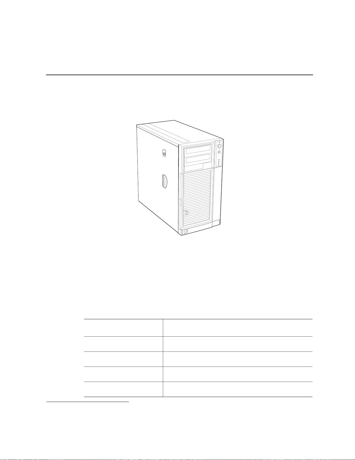
This chapter describes the main features of the Intel® Server Chassis SC5650. The
location of important chassis components and connections, as well as a description of
LED identification, are also presented.
AF000307
®
Figure 1. Front View of Intel
®
The Intel
Server Chassis SC5650 is a 5.2U pedestal1 server chassis and is available in
three configurations: DP (dual-processor), WS (workstation), BRP (base redundant
power) and UP(single-processor). The chassis is designed to support the Intel
Server Chassis SC5650
®
Server
Boards S5500BC, S5520HC, S5500HCV, S5520SC, and S3420GP family. The type of
server board supported depends on the configuration purchased. See Table 1 for a list of
the Intel
®
server boards supported by each server chassis configuration.
Table 1. Breakdown of Intel® Server Chassis SC5650 Configurations
®
Intel
Server Chassis SC5650
Configuration
Intel® Server Chassis SC5650
DP (Dual-processor)
®
Server Chassis SC5650
Intel
WS (Workstation)
®
Server Chassis SC5650
Intel
BRP (Base Redundant Power)
®
Intel
Server Chassis SC5650
UP (Single-Processor)
1. The Intel® Server Chassis SC5650 can be configured as a rack-mountable server chassis when outfitted with the
optional Rack Mount Kit (order code APP3RACKIT).
Intel® Server Boards S5500BC, S5520HC, and S5520HCV
Intel® Server Board S5520SC
Intel® Server Boards S5500BC, S5520HC, and S5500HCV
Intel® Server Boards S3420GP Family
®
Intel
Server Boards Supported
1
Intel® Server Chassis SC5650-DP/WS/BRP/UP Service Guide 1
Page 20

Server Chassis Features
NOTES:
1. For updated server board support, go to: http://support.intel.com/support/motherboards/server/
chassis/sc5650/
Table 2 summarizes the features of the Intel® Server Chassis SC5650.
Table 2. Server Chassis Features
®
Server
Intel
Configuration Intel® Server Chassis SC5650DP
Intel® Server
Board Support
Power Delivery 600-W PFC Intel validated PSU
System Cooling One tool-less, 120-mm chassis fan. One tool-less 120-mm PCI fan. One tool-
Peripheral Bays Two tool-less, multi-mount 5.25-in. peripheral bays. One standard 3.5-in removable media
Drive Bays Includes one tool-less fixed drive bay for up to six fixed drives.
PCI Slots Seven slots, support for six full-length, full-height PCI cards with tail card guide
Form Factor 5.2U tower, convertible to 6U rack mount.
Front Panel LEDs for NIC1, NIC2, HDD activity, power status, and syste m fault status.
External front
connectors
Color Black
Construction 1.0-mm, zinc-plated sheet metal, meets Intel Cosmetic Spec # C25432
Chassis ABS Fire retardant, non-brominated, PC-ABS
with integrated cooling fan.
less 92-mm drive bay fan.
peripheral bay.
and one half-length PCI slot.
Switches for power, NMI, and reset.
Integrated temperature sensor for fan speed management.
Two USB ports
• Intel
• Intel
Intel
S5500HCV
®
Server Board S5500BC
®
Server Board S5520HC/
®
Server Board
Chassis
SC5650BRP
®
• Intel
• Intel
600-W PFC Intel
validated PSU with
integrated cooling
fan. One additional
600-W PSU can be
added for
redundancy.
Server
Board
S5500BC
®
Server
Board
S5520HC/
®
Intel
Server
Board
S5500HCV
Intel® Server
Chassis
SC5650WS
®
• Intel
1000-W PFC Intel
validated PSU with
integrated cooling
fan.
Server
Board
S5520SC
Intel® Server
Chassis
SC5650UP
• Intel
400-W PFC
Intel validated
PSU with
integrated
cooling fan.
One tool-less,
120-mm
chassis fan.
One tool-less
92-mm drive
bay fan.
Full-length, fullheight PCI slot5
and six, halflength, fullheight PCI slot
4
®
Server
Board
S3420GP
Family
2 Intel® Server Chassis SC5650-DP/WS/BRP/UP Service Guide
Page 21
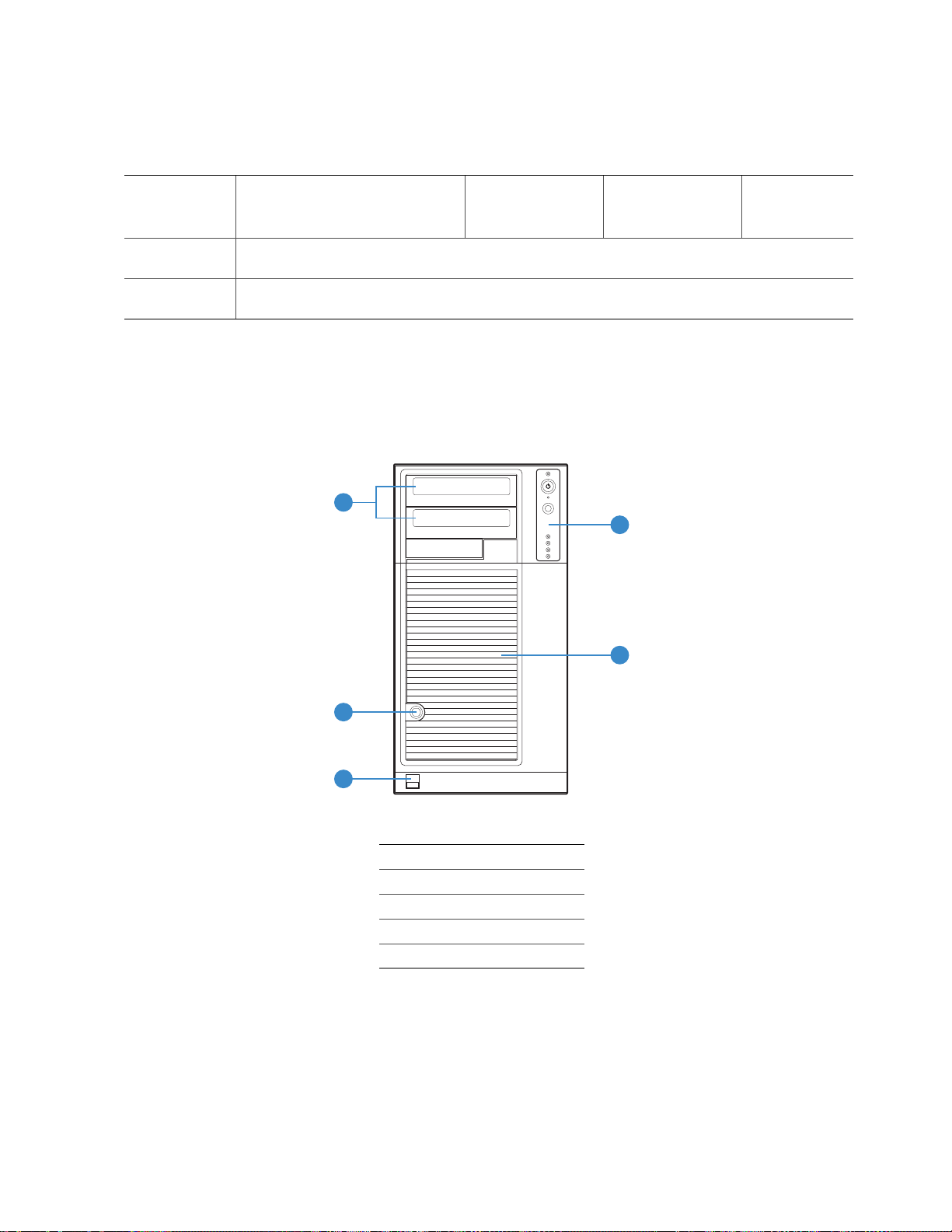
Table 2. Server Chassis Features
B
C
Configuration Intel® Server Chassis SC5650DP
®
Server
Intel
Chassis
SC5650BRP
Server Chassis Features
Intel® Server
Chassis
SC5650WS
Intel® Server
Chassis
SC5650UP
Dimensions
Pedestal
Dimensions
Rack
17.8 in (45.2 cm) x 9.256 in (23.5 cm) x 19 in (48.3 cm)
9.256 in (23.5 cm) x 17.6 in (44.7 cm) x 19 in (48.3 cm)
Component Identification
Front View Components
A
D
E
TP02345
A. 5.25-in Device Drive Bays
B. Front Panel
C. Drive Bay Access Door
D. Door Lock
E. Front Panel USB Ports
Figure 2. Front View Components (with Front Bezel Assembly)
Intel® Server Chassis SC5650-DP/WS/BRP/UP Service Guide 3
Page 22
Server Chassis Features
2
A
B
C
D
E
TP0088
A. 5.25-in Device Drive Bays
B. 3.5-in Device Drive Bay
C. Hard Drive Cage
D. Drive Bay EMI Shield (shown open)
E. Front Panel USB Ports
Figure 3. Front View Components (without Front Bezel Assembly)
4 Intel® Server Chassis SC5650-DP/WS/BRP/UP Service Guide
Page 23
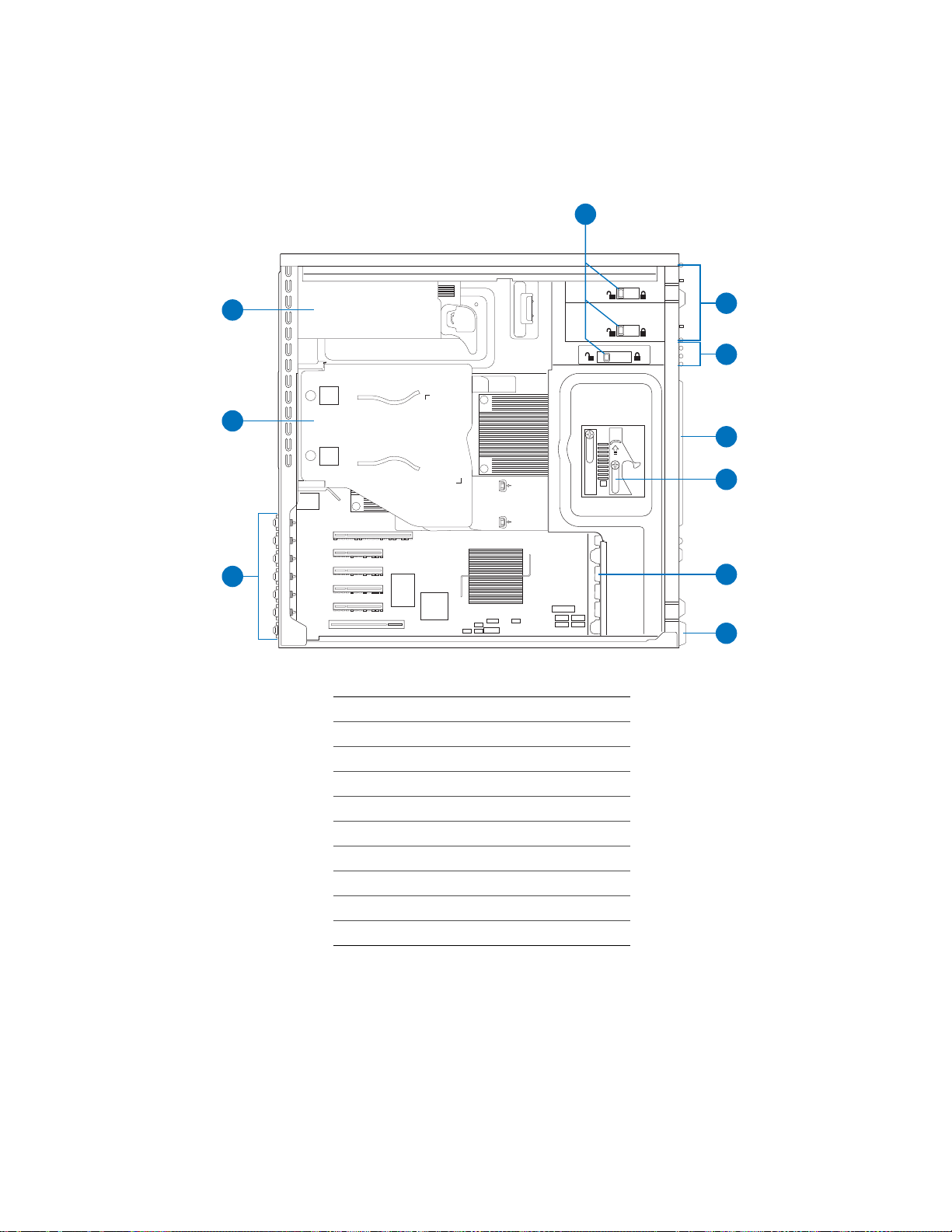
Internal Components
Server Chassis Features
A
J
LOCK
B
C
I
D
E
REMOVE FOR DUAL CPU OPERATION
WARNING: IMPROPER INSTALLATION &
REMOVAL OF DUCT CAN CAUSE DAMAGE
TO THE SERVER BOARD. INSTALL &
REMOVE THE DUCT WITH CAUTION
H
F
G
AF002995
A. Tool-less Device Bay Locks
B. 5.25-in Device Bays
C. 3.5-in Device Bay
D. Drive Bay EMI Shield
E. Drive Cage Retention Mechanism
F. PCI Add-in Card Guide
G. Front Panel USB Ports
H. Rear Tool-less PCI Retention Mechanisms
I. Fan Duct / System Fan Assembly
J. Power Supply
Figure 4. Internal Components (DP/WS/BRP Configuration Shown)
Intel® Server Chassis SC5650-DP/WS/BRP/UP Service Guide 5
Page 24
Server Chassis Features
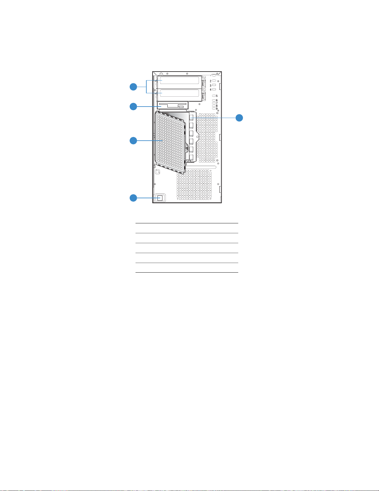
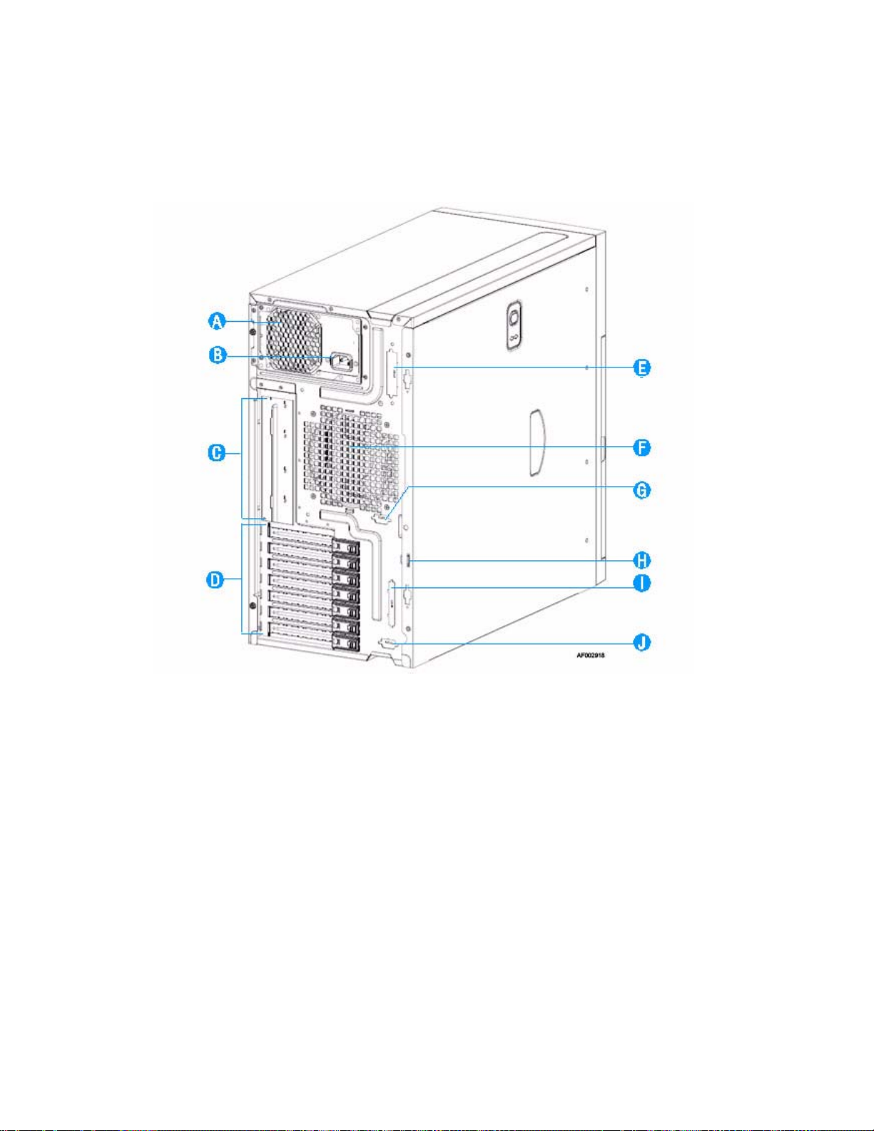
Back Panel Components
6 Intel® Server Chassis SC5650-DP/WS/BRP/UP Service Guide
Page 25
A. Power Supply
A
C
F
H
NOTE: Fixed Power Supply shown. Your Power Supply may
vary depending on chassis configuration purchased
B. A/C Power In
Server Chassis Features
Front Panel
NOTE: Fixed Power Supply shown. Your Power Supply may
vary depending on chassis configuration purchased.
C. I/O Shield
NOTE: I/O connectors vary, depending on the server board
installed. See your server board documentation for
port identification.
D. PCI Add-in Card slots
E. External SCSI knockout
F. System Fan
G. Serial B port knockout (UP only)
H. Location to install padlock Loop
I. External SCSI knockout
J. Alternate Serial B port knockout
Figure 5. Back Panel Components
B
D
E
G
TP02346
Intel® Server Chassis SC5650-DP/WS/BRP/UP Service Guide 7
Page 26

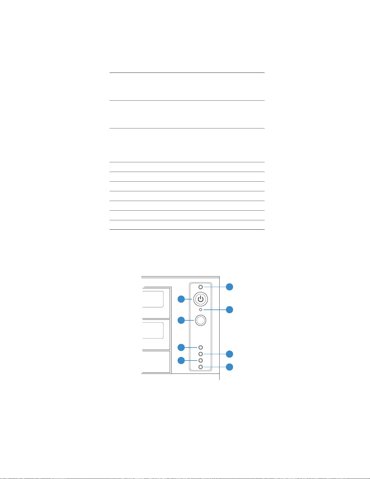
Server Chassis Features
NOTES:
Callout Feature
A. Power/Sleep LED Continuous green light indicates the system has power applied to it.
B. Power Button Powers the system off or on.
C. NMI Button Used to force system halt and dump memory contents to screen or file.
D. Reset Button Reboots and initializes the system.
E.
F.
G. Hard Drive Activity
H. Status LED Solid green indicates system ready (not supported by all server boards).
NIC 1 Activity LED
NIC 2 Activity LED
LED
1,2
Function
Continuous amber light indicates the system is in S1 Sleep state.
No light indicates the power is off / or the system is in S4 Sleep state.
Continuous green light indicates a link between system and network.
Blinking green light indicates network activity.
No light indicates the NIC is disconnected.
Random blinking green light indicates hard drive activity (SAS/SATA).
Continuous amber light indicates a hard drive fault.
No light indicates no hard disk drive activity.
Blinking green indicates processor or memory disabled.
Solid amber indicates a critical temperature or voltage fault, or a missing
CPU/terminator.
Blinking amber indicates a power fault, fan fault, or a non-critical
temperature or voltage fault.
No light indicates a fatal error during POST.
1. LED status may vary depending on server board integrated.
Figure 6. Front Panel Components
Peripheral Devices
The server chassis provides locations and hardware for installing hard drives, a floppy
drive, CD-ROM drive, DVD-ROM drive, or tape drive. You must purchase the drives
separately. The following figure shows the available options.
8 Intel® Server Chassis SC5650-DP/WS/BRP/UP Service Guide
Page 27
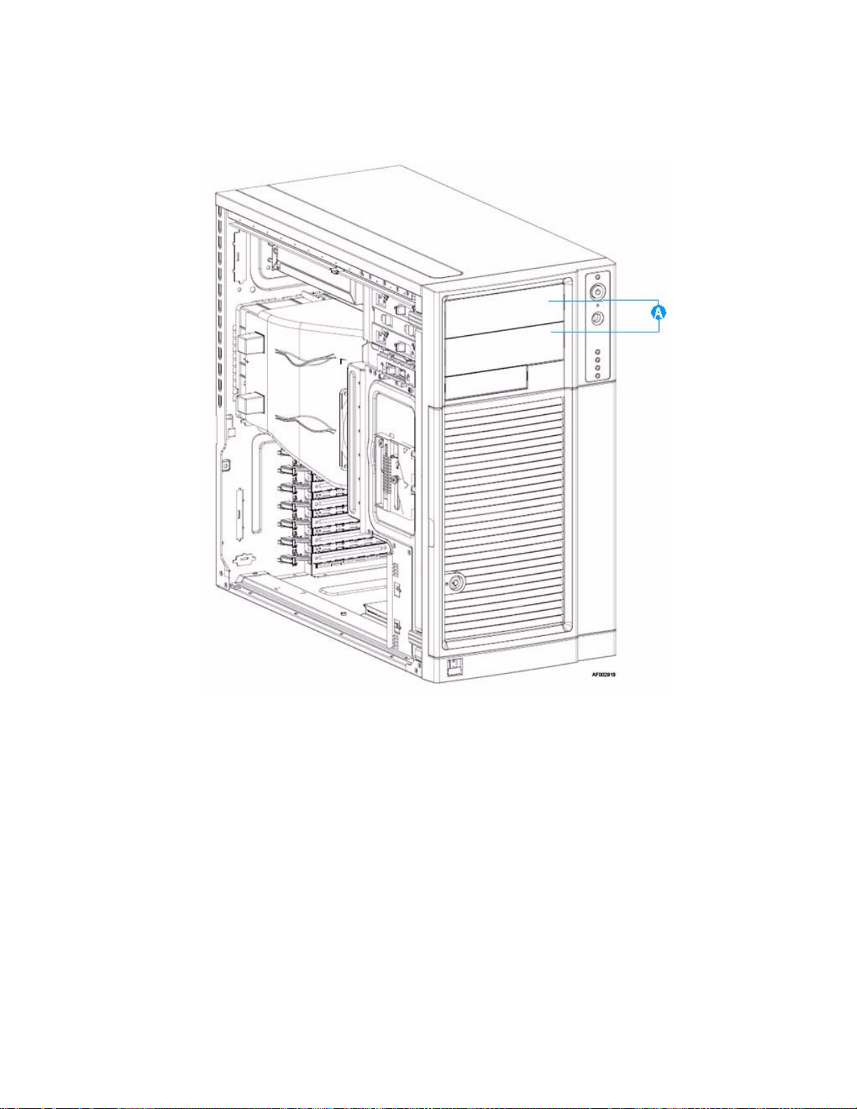
Server Chassis Features
NOTE: It is recommended that screws be used to secure large devices if shipping chassis
integrated.
Figure 7. Optional Peripheral Devices (DP/WS/BRP configuration shown)
Hard Disk Drives
The server chassis ships with one fixed hard drive cage capable of supporting up to six
cabled 3.5-in x 1-in hard drives. Power requirements for each individual hard drive may
limit the maximum number of drives that can be integrated into the server chassis.
You may purchase an optional hot-swap or SAS/SATA backplane hard drive cage
(capable of handling up to six hot-swappable, SATA or SAS hard drives) to replace the
fixed hard drive cage. See Table 3 for order code information.
For instructions on installing hard drives, see “Installing and Removing a Fixed Hard
Drive”.
Intel® Server Chassis SC5650-DP/WS/BRP/UP Service Guide 9
Page 28

Server Chassis Features
Note: Drives can consume up to 18.4 watts of power each. Drives must be specified to run at a
maximum ambient temperature of 45C.
®
Note: The Intel
“Additional Information and Software” for a web link to a list of supported hardware.
Server Chassis SC5650 does not support all Serial ATA hard drives. See
Front Bezel Assembly
The front bezel assembly provides a snap-on design that allows for maximum airflow
through the server chassis.
All configurations of the server chassis ship with a two-piece front bezel assembly.
Rack-Mounted Systems
Your Intel® Server Chassis SC5650 can be optionally mounted into a rack. Instru ctions for
installing your chassis into a rack are included with the rail kit.
The order number for the rack mounting kit is APP3RACKIT.
10 Intel® Server Chassis SC5650-DP/WS/BRP/UP Service Guide
Page 29
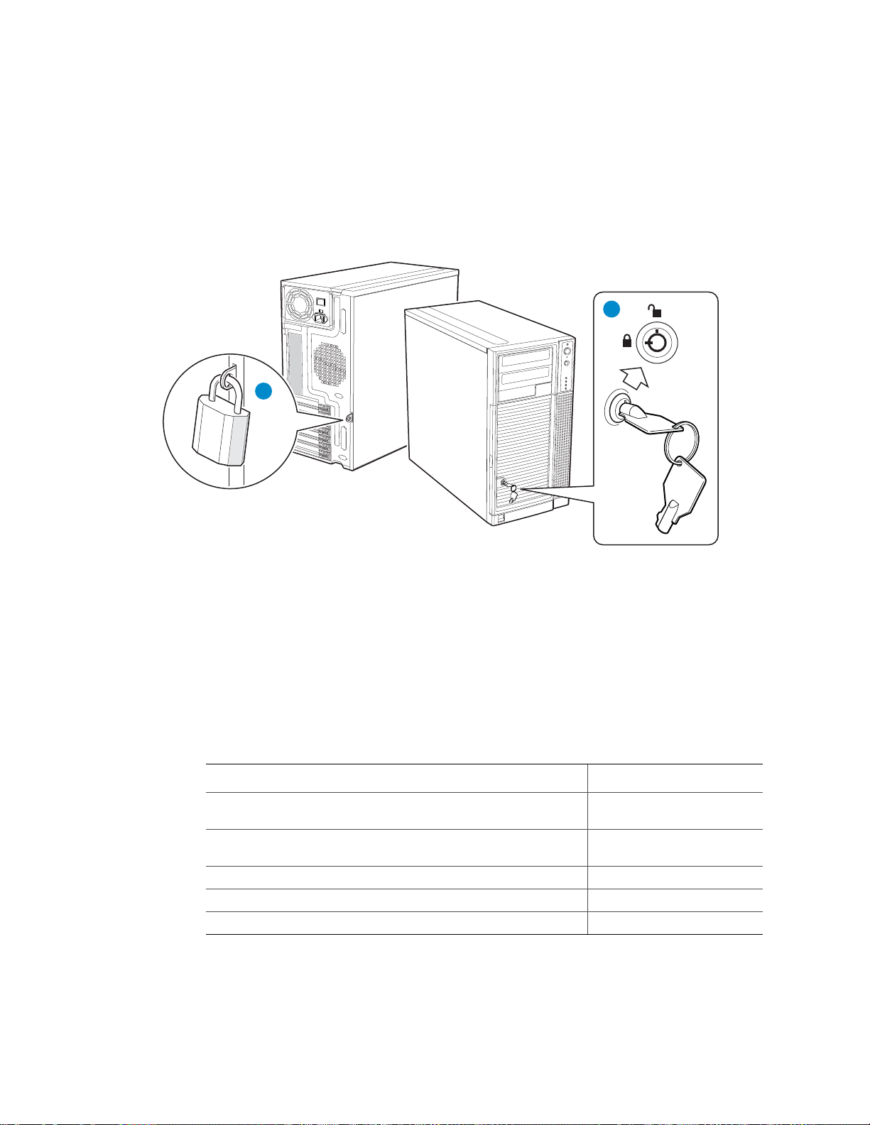
Mechanical Locks
AF000308
A
B
All configurations of the server chassis can support the installation of a padlock loop (see
letter “A” in the following figure) at the rear of the chassis. Additionally, the server
chassis ships with a two-position mechanical lock (see letter “B”) on the front bezel
assembly to prevent access to the hard drives and the interior of the chassis.
Server Chassis Features
Figure 8. Mechanical Locks
Accessories and Order Codes
For a complete list of spares and accessories available for your chassis, see:
http://support.intel.com/go/serverbuilder
Table 3. Accessories and Order Codes
6-Drive Hot-Swap, Expander SATA/SAS Backplane Assembly
Cage Kit
6-Drive Hot-Swap, Non-Expanded SATA/SAS Backplane
Assembly Cage Kit
Hot-Swap Drive Cooling and Mounting Kit APPTHSDBKIT
Hot Swap Conversion Kit APP3HSDBKIT
Rack Mount Kit APP3 RACKIT
Note: AXX6DRV3GEXP should be used with APP3HSDBKIT; AXX6DRV3GR should be used
with APPTHSDBKIT.
Accessory Order Code
AXX6DRV3GEXP
AXX6DRV3GR
Intel® Server Chassis SC5650-DP/WS/BRP/UP Service Guide 11
Page 30

Server Chassis Features
12 Intel® Server Chassis SC5650-DP/WS/BRP/UP Service Guide
Page 31

2 Hardware Installations and Upgrades
This document provides instructions for adding and replacing chassis components. For
instructions on replacing components on the server board, such as the processor and
memory DIMMs, see the instructions provided with the server board.
Before You Begin
Before working with your server product, review the important safety information listed
in Appendix A, “Safety Information”.
Tools and Supplies Needed
• Phillips* (cross head) screwdriver (#1 bit and #2 bit)
• Needle-nosed pliers
• Anti-static wrist strap and conductive foam pad (recommended)
• Hex nut driver (6 mm)
System References
All references to the left, right, front, top, and bottom assume the reader is facing the front
of the chassis as it would be positioned for pedestal operation.
Removing and Installing the Left Side Cover
Warning: This chassis must be operated with the left side cover installed to ensure proper cooling.
Removing the Left Side Cover
The Intel® Server Chassis SC5650 must be operated with the left side cover in place to
ensure proper cooling. You must remove the left side cover to add or replace components
inside of the platform. Before removing the left side cover, power down the server and
unplug all peripheral devices and the AC power cable.
Note: You may need a non-skid surface or a stop behind the chassis to prevent the chassis from
sliding on your work surface.
1. Observe the safety and ESD precautions listed in Ap pend ix A, “Safety Information”.
2. Turn off all peripheral devices connected to the server. Turn off the server.
3. Disconnect the AC power cord(s).
Intel® Chassis SC5650-DP/WS/BRP/UP Service Guide 13
Page 32

Hardware Installations and Upgrades
4. If present, remove the two screws (see letter “A” in the following figure). Push in on
the latch with your right hand (see letter “B”), and with your left hand, grasp the rear
cover clasp and slide the left side cover rearward to remove from chassis (see letter
“C”).
A
B
C
A
Figure 9. Removing Left Side Cover
TP00559
Installing the Left Side Cover
Warning: This chassis must be operated with the left side cover installed to ensure proper cooling.
1. Slide the left side cover on the chassis and latch securely (see letter “A” in the
following figure).
2. (Optional) Replace screws (see letter “B”).
B
A
B
Figure 10. Installing Left Side Cover
3. Reconnect all peripheral devices and the AC power cord. Power up the server.
14 Intel® Chassis SC5650-DP/WS/BRP/UP Service Guide
TP00831
Page 33

Hardware Installations and Upgrades
Removing and Installing the Right Side Cover
Warning: This chassis must be operated with the right side cover installed to ensure proper cooling
Removing the Right Side Cover
1. Observe the safety and ESD precautions listed in Ap pend ix A, “Safety Information”.
2. Power down the server and unplug all peripheral devices and the AC power cable.
3. Remove the left side cover. For instructions, see “Removing the Left Side Cover”.
4. If it is installed, remove the front bezel assembly. For instructions, see “Removing the
Front Bezel Assembly”.
5. Remove the two screws (see letter “A” in the following figure”) securing the right
side cover to the chassis. Lift the right side cover off the chassis.
A
A
TP01736
Figure 11. Removing Right Side Cover from Chassis
Intel® Chassis SC5650-DP/WS/BRP/UP Service Guide 15
Page 34

Hardware Installations and Upgrades
Installing the Right Side Cover
1. Reinstall the right side cover. Reinstall the two screws.
Warning: This chassis must be operated with the right side cover installed to ensure proper cooling.
TP01741
Figure 12. Re-installing Right Side Cover on Chassis
2. Reinstall the front bezel assembly. For instructions, see “Installing the Front Bezel
Assembly”.
3. Reinstall the left side cover. For instructions, see “Installing the Left Side Cover”
4. Reconnect all peripheral devices and the AC power cable. Power up the server.
16 Intel® Chassis SC5650-DP/WS/BRP/UP Service Guide
Page 35

Hardware Installations and Upgrades
Removing and Installing the Front Bezel Assembly
All configurations of the Intel® Server Chassis SC5650 ship with a two-piece front bezel
assembly.
Removing the Front Bezel Assembly
1. Observe the safety and ESD precautions listed in Ap pend ix A, “Safety Information”.
2. Turn off all peripheral devices connected to the server. Turn off the server.
3. Disconnect the AC power cord.
4. Remove the left side cover. For instructions, see “Removing the Left Side Cover”.
5. Disengage the two bezel tabs from the left side of the chassis (see letter “A” in the
following figure). Rotate the left side of the front bezel assembly outward slightly (see
letter “B”). Disengage the three clips that attach the right side of the front bezel
assembly to the chassis and remove (see letter “C”).
C
A
C
C
A
B
TP02034
Figure 13. Removing Front Bezel Assembly (DP/WS/BRP configuration shown)
Intel® Chassis SC5650-DP/WS/BRP/UP Service Guide 17
Page 36

Hardware Installations and Upgrades
Installing the Front Bezel Assembly
1. Line up the three clips on the right side of the front bezel assembly with the
corresponding slots on the right side of the chassis (see letter “A” in the following
figure). Engage the clips with the slots (see letter “B”). Rotate the left side of the front
bezel assembly towards the chassis (see letter “C”). Snap the two bezel tabs into the
corresponding recesses at the left edge of the chassis front panel (see letter “D”).
A
A
D
A
B
A
D
Figure 14. Installing the Front Bezel Assembly (DP/WS/BRP configuration shown)
2. Reinstall the left side cover. For instructions, see “Installing the Left Side Cover”.
3. Reconnect all peripheral devices and the AC power cable. Power up the server.
C
TP02035
Installing or Removing a Server Board
Note: The type of Intel® Server Board you can install in your chassis depends on the model of
chassis you purchased. For a breakout of server board/chassis model compatibility, see
Table 1, “Breakdown of Intel® Server Chassis SC5650 Configurations”.
To install or remove a server board, do the following:
1. Observe the safety and ESD precautions listed in Appendix A, “Safety Information”.
2. Power down the server and unplug all peripheral devices and the AC power cable.
3. Remove the left side cover. For instructions, see “Removing the Left Side Cover”.
4. Remove the front bezel assembly. For instructions, see “Removing the Front Bezel
Assembly”.
18 Intel® Chassis SC5650-DP/WS/BRP/UP Service Guide
Page 37

Hardware Installations and Upgrades
5. Loosen thumb screw and remove the drive cage EMI shield (see letter “A” in the
following figure).
A
B
TP01869
Figure 15. Removing Drive Cage EMI Shield from Fixed Drive Cage (DP/WS/BRP
configuration shown)
6. Disconnect cables from any installed fixed hard drives. If necessary, remove hard
drives from fixed hard drive cage. For instructions on removing fixed hard drives, see
“Removing a Fixed Hard Drive”.
Intel® Chassis SC5650-DP/WS/BRP/UP Service Guide 19
Page 38

Hardware Installations and Upgrades
7. Push the blue plastic release mechanism upward to release the fixed hard drive cage
(see letter “A” in the following figure). Once released, pull the fixed hard drive cage
from the chassis (see letter “B”).
A
B
TP02038
Figure 16. Removing Fixed Hard Drive Cage (DP/WS/BRP configuration shown)
8. Remove any PCI add-in boards that are present.
9. For Intel
®
Server Board SC5500BC Only: Remove the PCI card guide by pressing
in on the blue tabs (see letter “A” in the following figure) and pulling the PCI card
guide outward (see letter “B”).
A
B
TP01732
Figure 17. Removing PCI Card Guide
20 Intel® Chassis SC5650-DP/WS/BRP/UP Service Guide
Page 39

Hardware Installations and Upgrades
10. If installing a server board, refer to your Intel® Server Board User’s Guide and/or
Quick Start User’s Guide for installation instructions. Use the mounting screws,
bumpers and standoffs (if necessary) that came with your chassis to secure the server
board to the chassis. Make sure the server board is properly seated and then tighten
the screws firmly, starting with the screws at the center of the server board.
If removing a server board
additional removal instructions, refer to your Intel
, disconnect all cables connected to the server board. For
®
Server Board User’ s Guide and/or
Quick Start User’s Guide.
11. For Intel
®
Server Board SC5500BC Only: Re-install the PCI card guide. Insert tabs
on left side of PCI card guide into slots in chassis (see letter “A” in the following
figure). Swing PCI card guide into chassis until right-side blue tabs snap into place
(see letter “B”).
A
B
TP01735
Figure 18. Re-installing PCI Card Guide into Chassis
Intel® Chassis SC5650-DP/WS/BRP/UP Service Guide 21
Page 40

Hardware Installations and Upgrades
12. Slide the fixed hard drive cage into the drive bay slot of the chassis. You should hear a
click when the blue plastic retention mechanism locks into place.
TP02039
Figure 19. Inserting Fixed Hard Drive Cage into Chassis (DP/WS/BRP configuration
only)
13. If pre vio usly removed, install fixed hard drives and connect power and data cables.
For instructions, see “Installing a Fixed Hard Drive”.
22 Intel® Chassis SC5650-DP/WS/BRP/UP Service Guide
Page 41

Hardware Installations and Upgrades
14. Re-attach the drive cage EMI shield to the fixed hard drive cage and tighten the thumb
screw.
AF000315
Figure 20. Re-attaching Drive Cage EMI Shield
15. Re-install the front bezel assembly . For instructions, see “Removing and Installing the
Front Bezel Assembly”
16. Re-install the left side cover. For instructions, see “Installing the Left Side Cover”
17. Plug all peripheral devices and the AC power cable(s) back into the server. Power up
the server.
Intel® Chassis SC5650-DP/WS/BRP/UP Service Guide 23
Page 42

Hardware Installations and Upgrades
Installing and Removing a Fixed Hard Drive
You can install up to six fixed hard drive s in the fixed hard drive cage that ships with the
®
Server Chassis SC5650. Power requirements for each individual hard drive may
Intel
limit the maximum number of drives that can be integrated into the server chassis.
Note: The Intel
®
Server Chassis SC5650 does not support all hard drives. See “Additional
Information and Software” for a web link to a list of supported hard drives.
Installing a Fixed Hard Drive
Caution: Fixed drives are NOT hot-swappable. Before removing or replacing the drive, you must
first take the server out of service, turn off all peripheral devices connected to the system,
turn off the system by pressing the power button, and unplug the AC power cord from the
system or wall outlet.
Warning: You MUST populate drive ba y slots 1, 3, and 5 first. Failure to do so could result in
thermal issues within the chassis.
1
2
3
4
5
6
AF000316
Note: SAS/SATA drives illustrated.
Figure 21. Drive Bay Slot Order
1. Observe the safety and ESD precautions listed in Appendix A, “Safety Information”.
2. Power down the server and unplug all peripheral devices and the AC power cable.
24 Intel® Chassis SC5650-DP/WS/BRP/UP Service Guide
Page 43

Hardware Installations and Upgrades
3. Remove the left side cover. For instructions, see “Removing the Left Side Cover”.
4. Remove the front bezel assembly. For instructions, see “Removing the Front Bezel
Assembly”.
5. Loosen thumb screw and remove the drive cage EMI shield (see letter “A” in the
following figure).
A
B
TP01869
Figure 22. Removing Drive Cage EMI Shield from Chassis (DP/WS/BRP configuration
shown)
6. Remove any PCI add-in boards that use the PCI card guide. For instructions, see
“Removing PCI Add-in Boards”.
Intel® Chassis SC5650-DP/WS/BRP/UP Service Guide 25
Page 44

Hardware Installations and Upgrades
7. Remove the PCI card guide by pressing in on the blue tabs (see letter “A” in the
following figure) and pulling the PCI card guide outward (see letter “B”).
Figure 23. Removing PCI Card Guide
A
B
TP01732
8. Route the required power cables (connectors P7-P10 for DP/BRP/WS, P6-P8 and
P10-P12 for UP) from behind the PCI card guide through the cable routing area at the
bottom of the fixed drive cage.
AF000317
Figure 24. Routing Hard Drive Power Cables
26 Intel® Chassis SC5650-DP/WS/BRP/UP Service Guide
Page 45

Hardware Installations and Upgrades
9. Pull the drive latch forward to unlatch the drive locking assembly for the drive bay
you want to install a hard drive in.
AF000318
Figure 25. Unlatching Drive Latch
10. Insert fixed hard drive into drive bay and push until it stops. Ensure the power and
data connector end of the hard drive are facing forward.
AF000319
Figure 26. Inserting Hard Drive into Drive Cage
Intel® Chassis SC5650-DP/WS/BRP/UP Service Guide 27
Page 46

Hardware Installations and Upgrades
11.Push drive latch in to lock hard drive into drive bay.
AF000320
Figure 27. Latching Drive Latch
12. Install additional drives as necessary.
Warning: You MUST populate drive ba y slots 1, 3, and 5 first. Failure to do so could result in
thermal issues within the chassis.
1
2
3
4
5
6
AF000316
Figure 28. Drive Bay Slot Order
28 Intel® Chassis SC5650-DP/WS/BRP/UP Service Guide
Page 47

Hardware Installations and Upgrades
13. Install power (see letter “A” in the following figure) and data (see letter “B”) cables to
each of the installed drives.The cables route through the oval opening at the bottom of
the fixed drive cage.
A
B
AF000429
Figure 29. Cabling a Fixed Hard Drive
14. Re-attach the drive cage EMI shield to the chassis and tighten the thumb screw.
AF000315
Figure 30. Re-installing Drive Cage EMI Shield
Intel® Chassis SC5650-DP/WS/BRP/UP Service Guide 29
Page 48

Hardware Installations and Upgrades
15. Re-install the PCI card guide. Insert tabs on the left side of PCI card guide into slots in
chassis (see letter “A” in the following figure). Swing PCI card guide into chassis
until right-side blue tabs snap into place (see letter “B”).
A
B
TP01735
Figure 31. Re-installing PCI Card Guide
16. Re-install any PCI add-in cards that were removed. For instructions, see “Installing
PCI Add-in Boards”.
17. Re-insta ll the front bezel assembly. For instructions, see “Installing the Front Bezel
Assembly”
18. Re-insta ll the left side cover. For instructions, see “Installing the Left Side Cover”
19. Plug all peripheral devices and the AC power cable back into the server. Power up the
server.
Removing a Fixed Hard Drive
Caution: Fixed drives are NOT hot-swappable. Before removing or replacing the drive, you must
first take the server out of service, turn off all peripheral devices connected to the system,
turn off the system by pressing the power button, and unplug the AC power cord from the
system or wall outlet.
1. Observe the safety and ESD precautions listed in Appendix A, “Safety Information”.
2. Power down the server and unplug all peripheral devices and the AC power cable.
3. Remove the left side cover. For instructions, see “Removing the Left Side Cover”.
4. Remove the front bezel assembly. For instructions, see “Removing and Installing the
Front Bezel Assembly”.
30 Intel® Chassis SC5650-DP/WS/BRP/UP Service Guide
Page 49

Hardware Installations and Upgrades
5. Loosen thumb screw (see letter “A” in the following figure). Apply slight pressure to
the right side of drive bay access door and swing door outward (see letter “B”).
A
B
TP01869
Figure 32. Removing Drive Cage EMI Shield from Chassis (DP/WS/BRP configuration
shown)
6. Disconnect the data and power cables from the hard drive to be removed (see letter
“A” in the following figure). Pull the drive latch forward (see letter “B”) to unlatch
the drive-locking mechanism for the hard drive you want to remove.
B
A
AF000430
Figure 33. Preparing Fixed Hard Drive for Removal
Intel® Chassis SC5650-DP/WS/BRP/UP Service Guide 31
Page 50

Hardware Installations and Upgrades
7. Slide the hard drive out of the fixed hard drive cage and place the hard drive on an
anti-static surface. If replacing the hard drive, see “Installing a Fixed Hard Drive” for
instructions.
AF000431
Figure 34. Removing Fixed Hard Drive from Drive Bay
8. Re-attach the drive cage EMI shield to the chassis and tighten the thumb screw.
AF000315
Figure 35. Re-installing Drive Cage EMI Shield
9. Re-install the front bezel assembly. For instructions, see “Installing the Front Bezel
Assembly”.
10. Re-insta ll the left side cover. For instructions, see “Installing the Left Side Cover”.
32 Intel® Chassis SC5650-DP/WS/BRP/UP Service Guide
Page 51

Hardware Installations and Upgrades
11.Plug all peripheral devices and the AC power cable(s) into the server. Power up the
server.
Installing or Removing a DVD-ROM or CD-ROM Drive
Caution: CD-ROM and DVD-ROM drives are NOT hot-swappable. Before removing or replacing
the drive, you must first take the server out of service, turn off all peripheral devices
connected to the system, turn off the system by pressing the power button, and unplug the
AC power cord from the system or wall outlet.
Installing a DVD-ROM or CD-ROM Drive
1. Observe the safety and ESD precautions listed in Ap pend ix A, “Safety Information”.
2. Power down the server and unplug all peripheral devices and the AC power cable.
3. Remove the left side cover. For instructions, see “Removing the Left Side Cover”.
4. Remove the front bezel assembly. For instructions, see “Removing the Front Bezel
Assembly”.
5. Remove the EMI shield from the 5.25-in device drive bay (see letter “A” in the
following figure). Move latch to the “unlock” position (see letter “B”).
B
A
TP01063
Figure 36. Removing 5.25-in Drive EMI Shield (DP/WS/BRP configuration shown)
Intel® Chassis SC5650-DP/WS/BRP/UP Service Guide 33
Page 52

Hardware Installations and Upgrades
6. Insert the CD-ROM or DVD-ROM drive into the 5.25-in device drive bay (see letter
“C” in the following figure). Line up holes in CD-ROM drive with holes in chassis
(see letter “D”). Move latch to the “lock” position (see letter “E”). Connect power (P5
or P6connector from the power supply. An additional 4-pin IDE male-to SATA 15poin power cables adapter may be needed if the CD-ROM or DVD-ROM does not
have a 4-pin power connector.) and data cables to the rear of the CD-ROM or DVDROM drive (see letter “F”).
Figure 37. Installing CD-ROM or DVD-ROM Drive (DP/WS/BRP configuration shown)
7. If necessary, remove the filler panel from the front bezel assembly.
TP01723
34 Intel® Chassis SC5650-DP/WS/BRP/UP Service Guide
Page 53

8. Reinstall the front bezel assembly. For instructions, see “Installing the Front Bezel
C
E
Assembly”.
9. Reinstall the left side cover. For instructions, see “Installing the Left Side Cover”.
10. Reconnec t all peripheral devices and the AC power cable(s). Power up the server.
Removing a CD-ROM or DVD-ROM Drive
1. Observe the safety and ESD precautions listed in Ap pend ix A, “Safety Information”.
2. Power down the server and unplug all peripheral devices and the AC power cable.
3. Remove the chassis cover. For instructions, see “Removing the Left Side Cover”.
4. Remove the Front Bezel Assembly. For instructions, see “Removing the Front Bezel
Assembly”.
5. Disconnect the power and data cables from the rear of the CD-ROM or DVD-ROM
drive (see letter “F” in the following figure). Move latch to the “unlock” position (see
letter “D”). Slide CD-ROM or DVD-ROM drive out of the Device Drive Bay (see
letter “C”).
Hardware Installations and Upgrades
D
F
Power
Figure 38. Removing CD-ROM or DVD-ROM Drive (DP/WS/BRP configuration shown)
Data
AF003105
Intel® Chassis SC5650-DP/WS/BRP/UP Service Guide 35
Page 54

Hardware Installations and Upgrades
TP02048
6. If reinstalling a new CD-ROM or DVD-ROM drive, see “Installing a DVD-ROM or
CD-ROM Drive” for instructions. If not replacing the drive, reinstall the EMI shield
and front bezel filler panel, if available.
Figure 39. Installing 5.25-in Drive EMI Shield (DP/WS/BRP configuration shown)
7. Reinstall the front bezel assembly. For instructions, see “Installing the Front Bezel
Assembly”.
8. Reinstall the chassis cover. For instructions, see “Installing the Left Side Cover”.
9. Reconnect all peripheral devices and the AC power cable(s). Power up the server.
Installing and Removing PCI Add-in Boards
The following instructions describe how to install and remove a PCI add-in board in the
®
Server Chassis SC5650. These instructions depend on the server board. See your
Intel
server board documentation to determine PCI add-in board compatibility.
Caution: Do not overload the server board by installing add-in boards that draw excessive current.
Caution: PCI add-in boards can be extremely sensitive to electric static discharge (ESD) and
always require careful handling. After removing the add-in board from its protective
wrapper or from the server board, place it component side up on a grounded, static-free
surface or conductive foam pad. Do not slide the add-in board over any surface.
Installing PCI Add-in Boards
Note: Before installing any PCI add-in boards, you may want to install an operating system.
1. Observe the safety and ESD precautions listed in Appendix A, “Safety Information”.
2. Power down the server and unplug all peripheral devices and the AC power cable.
36 Intel® Chassis SC5650-DP/WS/BRP/UP Service Guide
Page 55

Hardware Installations and Upgrades
TP02049
3. Remove the left side cover. For instructions, see “Removing the Left Side Cover”.
4. Open the back panel PCI Add-in Card Retention Device by pressing open from the
inside of the chassis.
Figure 40. Opening PCI Add-in Card Retention Device (DP/WS/BRP configuration
shown)
5. If it is already not removed, remove the PCI slot shield by pushing the shield out from
the inside of the chassis.
TP01744
Figure 41. Removing PCI Slot Shield
6. Remove a PCI add-in board from its protective wrapper. Be careful not to touch the
components or gold-edge connectors. Place the board on an anti-static surface. Record
the type and serial number of the add-in board in your equipment log. Set jumpers or
switches on the board according to the manufacturer’s instructions.
Intel® Chassis SC5650-DP/WS/BRP/UP Service Guide 37
Page 56

Hardware Installations and Upgrades
7. Hold the PCI add-in board by its top edge or upper corners. Firmly press the add-in
board into an expansion slot on the server board (see letter “A” in the following
figure). Close the back panel PCI Add-in Card Retention Device (see letter “B”).
B
B
A
TP01745
Figure 42. Installing PCI Add-in Board
8. Repeat the previous steps until all PCI add-in boards are installed.
9. Attach cables, if necessary.
10. Reinstall the left side cover. For instructions, see “Installing the Left Side Cover”.
11.Reconnect all peripheral devices and the AC power ca ble. Power up the server.
Removing PCI Add-in Boards
Caution: PCI add-in boards can be extremely sensitive to electric static discharge (ESD) and
always require careful handling. After removing the add-in board from its protective
wrapper or from the server board, place it component side up on a grounded, static-free
surface or conductive foam pad. Do not slide the add-in board over any surface.
1. Observe the safety and ESD precautions listed in Appendix A, “Safety Information”.
2. Power down the server and unplug all peripheral devices and the AC power cable.
3. Remove the left side cover. For instructions, see “Removing the Left Side Cover”.
38 Intel® Chassis SC5650-DP/WS/BRP/UP Service Guide
Page 57

Hardware Installations and Upgrades
TP02049
4. Open the back panel PCI Add-in Card Retention Device by pressing open from the
inside of the chassis.
Figure 43. Opening PCI Add-in Card Retention Device (DP/WS/BRP configuration
shown)
5. Disconnect any cables that may be attached to the PCI add-in board that needs to be
removed.
6. Firmly grab the PCI add-in board by its top edge or upper corners and remove from
the expansion slot on the server board (see letter “A” in the following figure). Place
the removed add-in board in an anti-static protective wrapper. Close the back panel
PCI Add-in Card Retention Device (see letter “B”).
B
B
A
TP01724
Figure 44. Removing PCI Add-in Board
Intel® Chassis SC5650-DP/WS/BRP/UP Service Guide 39
Page 58

Hardware Installations and Upgrades
7. If available, replace the PCI slot shield by pressing the slot shield into the opening on
the chassis.
TP01726
Figure 45. Replacing PCI Slot Shield
8. Reinstall the left side cover. For instructions, see “Installing the Left Side Cover”.
9. Reconnect all peripheral devices and the AC power cable(s). Power up the server.
Replacing the Front Panel Board
Your server must be operated with a front panel board installed.
Caution: The front panel board is NOT hot-swappable. Before removing or replacing the front
panel board, you must first take the server out of service, turn off all peripheral devices
connected to the system, turn off the system by pressing the power button, and unplug the
AC power cord from the syste m or wall outlet.
1. Observe the safety and ESD precautions listed in Appendix A, “Safety Information”.
2. Power down the server and unplug all peripheral devices and the AC power cable.
3. Remove the left side cover. For instructions, see “Removing the Left Side Cover”.
4. Remove the front bezel assembly if it is installed. For instructions, see “Removing the
Front Bezel Assembly”.
40 Intel® Chassis SC5650-DP/WS/BRP/UP Service Guide
Page 59

Hardware Installations and Upgrades
5. Remove the two screws (see letter “A” in the following figure”) securing the right
side cover to the chassis. Lift the right side cover off the chassis.
A
A
TP01736
Figure 46. Removing Right Side Cover from Chassis
6. Remove the three screws securing the front panel board to the chassis.
TP01737
Figure 47. Unattaching Front Panel Board from Chassis
Intel® Chassis SC5650-DP/WS/BRP/UP Service Guide 41
Page 60

Hardware Installations and Upgrades
0
7. Carefully remove the front panel board through the opening in the left side of the
chassis (see letter “A” in the following figure). Disconnect the front panel cable (see
letter “B”) and the chassis intrusion cable (see letter “C”) from the front panel board.
A
Figure 48. Removing Front Panel Board from Chassis
B
C
AF000432
8. Remove standoffs from the old front panel and install on the new front panel.
TP0200
Figure 49. Removing Standoffs from Front Panel
42 Intel® Chassis SC5650-DP/WS/BRP/UP Service Guide
Page 61

Hardware Installations and Upgrades
9. Attach the front panel cable (see letter “A” in the following figure) and the chassis
intrusion cable (see letter “B”) to the new front panel board. Slide the new front panel
board through the opening in the left side of chassis (see letter “C”).
C
A
B
AF000433
Figure 50. Installing Front Panel Board in Chassis
10. Use one hand to align the front panel board in position inside the chassis. With your
other hand, tighten the three screws to secure the front panel board to the front of the
chassis.
TP01740
Figure 51. Positioning Front Panel Board in Chassis
Intel® Chassis SC5650-DP/WS/BRP/UP Service Guide 43
Page 62

Hardware Installations and Upgrades
11.Reinstall the right side cover. Reinstall the two screws.
Warning: This chassis must be operated with the right side cover installed to ensure proper cooling.
TP01741
Figure 52. Re-installing Right Side Cover on Chassis
12. Reinsta ll the front bezel assembly. For instructions, see “Installing the Front Bezel
Assembly”.
13. Reinstall the left side cover. For instructions, see “Installing the Left Side Cover”
14. Reconnect all pe ripheral devices and the AC power cable. Power up the server.
Replacing a System Fan
Caution: The system fan for the Intel® Server Chassis SC5650 is NOT hot swappable. Before
removing or replacing a fan, you must first take the server out of service, turn off all
peripheral devices connected to the system, turn off the system by pressing the power
button, and unplug the AC power cord from the system or wall outlet.
1. Observe the safety and ESD precautions listed in Appendix A, “Safety Information”.
2. Power down the server and unplug all peripheral devices and the AC power cable.
3. Remove the left side cover. For instructions, see “Removing the Left Side Cover”.
44 Intel® Chassis SC5650-DP/WS/BRP/UP Service Guide
Page 63

Hardware Installations and Upgrades
4. (For all server boards on DP/WS/BRP configuration EXCEPT Intel® Server Board
S5500BC) Remove the fan duct /system fan assembly.
Figure 53. Removing Fan Duct / System Fan Assembly (DP/WS/BRP configuration)
5. Disc onnec t the fan power cab le from the s erver board (see lett er “A” in the follo wing
figure). Remove the system fan from its snap-in bracket by pressing the two bracket
tabs outward (see letter “B”).
Figure 54. Removing System Fan from Chassis
Intel® Chassis SC5650-DP/WS/BRP/UP Service Guide 45
Page 64

Hardware Installations and Upgrades
6. (For UP config uration) Remove fan duct assembly and system fan by pushing the left
and right tabs outward and disengaging from snap-in bracket.
Figure 55. Removing Fan Duct / System Fan Assembly (UP configuration)
7. For Intel
new system fan in the snap-in bracket is shown in the following figure.
®
Server Board S5500BC only, install the fan guard. For installation, the
1
3
Figure 56. Installing System Fan in Chassis
8. (For all server boards on DP/WS/BRP configuration EXCEPT Intel
S5500BC) Re-install the fan duct / system fan assembly.
46 Intel® Chassis SC5650-DP/WS/BRP/UP Service Guide
®
Server Board
Page 65

Hardware Installations and Upgrades
Figure 57. Re-installing Fan Duct / System Fan Assembly (DP/WS/BRP configuration)
9. For UP only, insert the system fan and fan duct assembly into the snap-in bracket on
the chassis back panel.
Figure 58. Re-installing Fan Duct / System Fan Assembly (UP configuration)
10. Reconnect the fan cable to the server board. Refer to the User Guide that came with
your server board for connection location.
11.Install the left side cover. For instructions, see “Installing the Left Side Cover”.
12. Plug all peripheral devices and the AC power cable into the server. Power up the
server.
Intel® Chassis SC5650-DP/WS/BRP/UP Service Guide 47
Page 66

Hardware Installations and Upgrades
Replacing a Fixed Power Supply
Warning: Hazardous conditions, power supply: Hazardous voltage, current, and energy levels are
present inside the power supply . There are no user-serviceable parts inside it; servicing of
the power supply should only be done by technically qualified personnel.
Caution: The fixed power su pply is NOT hot-swappa ble in the DP, UP, and WS models of the Intel
Server Chassis SC5650. Before removing or replacing the fixed power supply, you must
first take the server out of service, turn off all peripheral devices connected to the system,
turn off the system by pressing the power button, and unplug the AC power cord from the
system or wall outlet.
To replace a fixed power supply, use the following instructions:
1. Observe the safety and ESD precautions listed in Appendix A, “Safety Information”.
2. Power down the server and unplug all peripheral devices and the AC power cable.
3. Remove the left side cover. For instructions, see “Removing the Left Side Cover”.
4. Disconnect all internal power cables from chassis components and server board.
5. Rotate the blue locking mechanism (see letter “A” in the following figure to the open
position.
®
A
TP01757
Figure 59. Unlocking Fixed Power Supply from Chassis
48 Intel® Chassis SC5650-DP/WS/BRP/UP Service Guide
Page 67

Hardware Installations and Upgrades
TP01754
TP01753
A
6. Once the f ixed power supp ly i s loose, p ush the power supply against the blue locking
mechanism and then lift the power supply out of the chassis.
Figure 60. Removing Fixed Power Supply from Chassis
7. Insert the new fixed power supply in chassis. Ensure the blue locking mechanism is
still in the open position. Make sure the new fixed power supply rests on the small
metal shelf on the side wall of the chassis (see letter “A” in the following figure).
Figure 61. Inserting Fixed Power Supply in Chassis
Intel® Chassis SC5650-DP/WS/BRP/UP Service Guide 49
Page 68

Hardware Installations and Upgrades
8. Rotate the blue locking mechanism to the locked position (see letter “A” in the
following figure).
A
TP01755
Figure 62. Locking Fixed Power Supply into Chassis
9. Rou te and connect the P1 , P2, P3 and P4 (for DP/BRP/WS), P1 and P2 (for UP)cables
to the server board. Refer to the Intel
Guide that came with your Intel
®
Server Board Quick Start User’s Guide or User
®
server board for appropriate power connections.
10. Route the P5 and P6 cables (for WS) to the PCI Express* graphic cards.
11.Route the P9 and P10 (for DP/BRP/WS), P3 and P4 (for UP) cables to the 5.25-in.
removable media device bays and connect to installed devices.
12. Route the P11, P12, P13, and P14 (for DP/BRP/WS), P6-P8 and P10-P12 (for UP)
cables to the hard drive cage and connect power cables to installed devices.
13. Install the left side cover. For instructions, see “Installing the Left Side Cover”.
14. Reconnect all pe ripheral devices and the AC power cable to the server. Power up the
server.
50 Intel® Chassis SC5650-DP/WS/BRP/UP Service Guide
Page 69

Hardware Installations and Upgrades
Installing an Additional Hot Swap Power Supply Module (BRP
configuration only)
Note: This install procedure only applies to a chassis with redundant power supply capability.
DO NOT perform this install procedure if your chassis has a fixed power supply.
Warning: Hazardous conditions, power supply: Hazardous voltage, current, and energy levels are
present inside the power supply . There are no user-serviceable parts inside it; servicing of
the power supply should be done only by technically qualified personnel.
1. Observe the safety and ESD precautions listed in Ap pend ix A, “Safety Information”.
.
2. Insert finger into hole in middle of filler panel and remove filler panel from chassis.
UP
UP
AF002947
Figure 63. Removing Power Supply Filler Panel
3. Insert new hot swap power supply module until it clicks into place.
Figure 64. Inserting Additional Hot Swap Power Supply Module
Intel® Chassis SC5650-DP/WS/BRP/UP Service Guide 51
Page 70

Hardware Installations and Upgrades
Removing a Hot Swap Power Supply (BRP configuration only)
Warning: Hazardous conditions, power supply: Hazardous voltage, current, and energy levels are
present inside the power supply . There are no user-serviceable parts inside it; servicing of
the power supply should be done only by technically qualified personnel.
1. Observe the safety and ESD precautions listed in Appendix A, “Safety Information”.
2. Remove power cable from defective power supply.
3. Press up on green latch (see letter “A” in t he following figure) while pulling on handle
(see letter “B”) to remove hot swap power supply from chassis.
Figure 65. Removing Hot Swap Power Supply Module from Chassis
4. Insert new hot swap power supply module.
52 Intel® Chassis SC5650-DP/WS/BRP/UP Service Guide
Page 71

Hardware Installations and Upgrades
Figure 66. Inserting Hot Swap Power Supply Module in Chassis
5. Connect power cable to replaced hot swap power supply.
Replacing a Hot Swap Power Supply Cage (BRP configuration only)
Warning: Hazardous conditions, power supply: Hazardous voltage, current, and energy levels are
present inside the power supply . There are no user-serviceable parts inside it; servicing of
the power supply should be done by technically qualified personnel.
1. Observe the safety and ESD precautions listed in Ap pend ix A, “Safety Information”.
2. Power down the server and unplug all peripheral devices and the AC power cable.
3. Remove the left side cover. For instructions, see “Removing the Left Side Cover”.
4. Press up on green latch (see letter “A”) while pulling on handle to remove hot swap
power supply module from chassis.
Intel® Chassis SC5650-DP/WS/BRP/UP Service Guide 53
Page 72

Hardware Installations and Upgrades
Figure 67. Removing Hot Swap Power Supply Module
5. Remove second (redundant) hot swap power supply module (or filler panel), if one is
present.
6. Disconnect all internal power cables from chassis components and server board.
7. Remove two internal screws (see letter “A” in the following figure) securing hot swap
power supply cage to chassis.
A
Figure 68. Detaching Hot Swap Power Supply Cage from Inside of Chassis
8. Remove five external screws securing back of power supply cage to chassis. Slide the
power supply cage out of the chassis.
54 Intel® Chassis SC5650-DP/WS/BRP/UP Service Guide
Page 73

Hardware Installations and Upgrades
A
B
Note: You may have to work the power cables through slot openings with your free hand as you
remove the power supply cage from the chassis.
TP01762
Figure 69. Detaching Hot Swap Power Supply Cage from Rear of Chassis
9. Remove the two screws (see letter “A” in the following figure) attaching the rear
support bracket to the old power supply cage. Remove the rear support bracket (see
letter “B”).
Figure 70. Removing Rear Support Bracket from Hot Swap Power Supply Cage
10. Attach the rear support bracket to the new power supply cage with the two screws
removed from the previous step.
Intel® Chassis SC5650-DP/WS/BRP/UP Service Guide 55
Page 74

Hardware Installations and Upgrades
Figure 71. Attaching Rear Support Bracket to Power Supply Cage
11.Insert new hot swap power supply cage into chassis. Secure back of hot swap power
supply cage to chassis with five screws.
Note: Ensure you r oute the power supply cables thr ough the power supply opening in the chassis
first before inserting the power supply cage.
TP01766
Figure 72. Securing Hot Swap Power Supply Cage to Rear of Chassis
12. Secure the inside panel of the hot swap power supply cage to chassis with two screws.
56 Intel® Chassis SC5650-DP/WS/BRP/UP Service Guide
Page 75

Hardware Installations and Upgrades
A
AF002934
Figure 73. Securing Hot Swap Power Supply Cage to Inside of Chassis
13. Route and connect the P1, P2, P3, and P4 cables to the server board. Refer to the
®
Intel
Server Board Quick Start User’s Guide or User Guide that came with your
®
server board for appropriate power connections.
Intel
14. Route the P5 and P6 cables to the PCI Express* graphic cards.
15. Route the P9 and P10 cables to the 5.25-in. removable media device bays and connect
to installed devices.
16. Route the P11, P12, P13, and P14 cables to the hard drive cage and connect power
cables to installed devices.
17. Reinstall the hot swap power supply module(s). The power supply module(s) clicks
into place when properly seated.
Intel® Chassis SC5650-DP/WS/BRP/UP Service Guide 57
Page 76

Hardware Installations and Upgrades
AF002929
Figure 74. Re-installing Hot Swap Power Supply Module(s)
18. Install the left side cover. For instructions, see “Installing the Left Side Cover”.
19. Reconnect all pe ripheral devices and the AC power cable(s) to the server. Power up
the server.
58 Intel® Chassis SC5650-DP/WS/BRP/UP Service Guide
Page 77

Hardware Installations and Upgrades
Installing Feet for a Pedestal-configured Chassis
Note: Do not install feet on your Intel® Server Chassis SC5650 if it is to be installed in a rack.
Only install feet on a pedestal-configured chassis.
1. Observe the safety and ESD precautions listed in Ap pend ix A, “Safety Information”.
2. Power down the server and unplug all peripheral devices and the AC power cable.
3. Lay the chassis down on its right side.
4. Insert rubber foot into chassis hole (see letter “A” in the following figure). Secure foot
to chassis by inserting a pin through the rubber foot (see letter “B”). Repeat process
for remaining feet.
A
B
TP01709
Figure 75. Installing Feet on Chassis
5. Put chassis in the upright position.
6. Reconnect all peripheral devices and the AC power cable to the server. Power up the
server.
Intel® Chassis SC5650-DP/WS/BRP/UP Service Guide 59
Page 78

Hardware Installations and Upgrades
60 Intel® Chassis SC5650-DP/WS/BRP/UP Service Guide
Page 79

3 Hot Swap Drive Cage Upgrade Install
Instructions (optional)
The fixed hard drive cage that ships with your Intel® Server Chassis SC5650 is
upgradeable to a hot swap drive cage with a SAS/SATA backplane. See your Intel
Representative for ordering information.
You can install up to six hot swap hard drives in the optional hot swap drive ca ge . Pow er
requirements for each individual hard drive may limit the maximum number of drives that
can be integrated into the server chassis.
®
Note: The Intel
Information and Software” for a web link to a list of supported hard drives.
Before You Begin
Before working with your server product, review the important safety information listed
in Appendix A, “Safety Information”.
Server Chassis SC5650 does not support all hard drives. See “Additional
Kits Required
• A hot swap conversion kit or a hot-swap drive cooling and mounting kit (part number:
APP3HSDBKIT or APPT HSDBKIT).
OR
• A SAS/SATA backplane with expander (part number AXX6DRV3GEXP).
OR
• A hot swap drive cage kit with a SAS/SATA backplane without expander (part
number AXX6DRV3GR)
Tools and Supplies Needed
• Phillips* (cross head) screwdriver (#1 bit and #2 bit)
• Needle-nosed pliers
• Anti-static wrist strap and conductive foam pad (recommended)
System References
All references to the left, right, front, top, and bottom assume the reader is facing the front
of the chassis as it would be positioned for pedestal operation.
Intel® Server Chassis SC5650-DP/WS/BRP/UP Service Guide 61
Page 80

Hot Swap Drive Cage Upgrade Install Instructions (optional)
Installing a Hot Swap Hard Drive Cage with a SAS/SATA Backplane
1. Observe the safety and ESD precautions listed in Appendix A, “Safety Information”.
2. Power down the server and unplug all peripheral devices and the AC power cable.
3. Remove the left side cover. For instructions, see “Removing the Left Side Cover”.
4. Remove the front bezel assembly. For instructions, see “Removing the Front Bezel
Assembly”.
5. Loosen the thumb screw and remove the fixed drive cage EMI shield.
A
B
TP01869
Figure 76. Removing Fixed Drive Cage EMI Shield from Chassis (DP/WS/
BRP configuration shown)
6. Disconnect cables from any fixed hard drives and remove hard drives from the fixed
hard drive cage. For instructions on removing fixed hard drives, see “Removing a
Fixed Hard Drive”.
62 Intel® Server Chassis SC5650-DP/WS/BRP/UP Service Guide
Page 81

Hot Swap Drive Cage Upgrade Install Instructions (optional)
7. Push the blue plastic release mechanism upward to release the fixed hard drive cage
(see letter “A” in the following figure). Once released, pull the fixed hard drive cage
from the chassis (see letter “B”).
A
B
TP02038
Figure 77. Removing Fixed Hard Drive Cage from Chassis (DP/WS/BRP
configuration shown)
8. Gather together the components for the hot swap drive cage installation. You should
have a hot swap drive cage with a SAS/SATA backplane, a side filler panel, a latch
plate, a fan bracket, and a fan.
Intel® Server Chassis SC5650-DP/WS/BRP/UP Service Guide 63
Page 82

Hot Swap Drive Cage Upgrade Install Instructions (optional)
5
9. Remove the stud screws from the top of the hot swap drive cage.
AF00293
Figure 78. Removing Stud Screws from Hot Swap Drive Cage
10. Attach the latch plate to the left side of the hot swap drive cage.
TP01060
Figure 79. Attaching Latch Plate to Hot Swap Drive Cage
64 Intel® Server Chassis SC5650-DP/WS/BRP/UP Service Guide
Page 83

Hot Swap Drive Cage Upgrade Install Instructions (optional)
AF002936
11.Attach the side filler panel to the right side of the hot swap drive cage.
TP01059
Figure 80. Attaching Filler Panel to Hot Swap Drive Cage
12. Remove the two thumb screws that secure the backplane to the hot swap drive cage.
Figure 81. Removing Thumb Screws from Backplane
Intel® Server Chassis SC5650-DP/WS/BRP/UP Service Guide 65
Page 84

Hot Swap Drive Cage Upgrade Install Instructions (optional)
13. Align the fan bracket with the three pegs on the drive cage (see letter “A” in the
following figure) and slide the fan bracket into position. Replace the two thumb
screws (see letter “B”).
Caution: The backplane may have slipped once the thumb screws were removed.
Ensure the backplane is positioned correctly before re-tightening the
thumb screws.
B
A
B
AF002937
Figure 82. Attaching Fan Bracket to Expanded Hot Swap Drive Cage
66 Intel® Server Chassis SC5650-DP/WS/BRP/UP Service Guide
Page 85

Hot Swap Drive Cage Upgrade Install Instructions (optional)
A
B
AF003066
Figure 83. Attaching Fan Bracket to Non-Expanded Hot Swap Drive Cage
Intel® Server Chassis SC5650-DP/WS/BRP/UP Service Guide 67
Page 86

Hot Swap Drive Cage Upgrade Install Instructions (optional)
14. Attach the fan to the fan bracket by placing two corners of the fan into the two holding
slots on the fan bracket. Press the fan into the fan bracket until it clicks into place.
Caution: Ensure the label and directional airflow arrow on fan are pointed out
(away from the backplane).
AF002940
Figure 84. Attaching Fan to Fan Bracket
68 Intel® Server Chassis SC5650-DP/WS/BRP/UP Service Guide
Page 87

Hot Swap Drive Cage Upgrade Install Instructions (optional)
AF003067
Figure 85. Attaching Fan to Fan Bracket Non-Expanded, Hot Swap Drive
Cage
Intel® Server Chassis SC5650-DP/WS/BRP/UP Service Guide 69
Page 88

Hot Swap Drive Cage Upgrade Install Instructions (optional)
TP02051
15. Slide the drive cage into the drive bay slot on the chassis. You should hear a click
when the blue plastic retention mechanism locks into place. Be sure to feed the fan
cable through the slot first so it exits through the back of the drive cage. Connect the
fan cable to its connector on the server board.
Figure 86. Inserting Hot Swap Drive Cage into Chassis (DP/WS/BRP
configuration shown)
16. Connect the fan cable to the appropriate connector on the server board. See your
server board documentation for information on the location of the fan cable connector.
70 Intel® Server Chassis SC5650-DP/WS/BRP/UP Service Guide
Page 89

Hot Swap Drive Cage Upgrade Install Instructions (optional)
17. Make the ba ckplane and server board/RAID controller card cable connections. Cable
instructions differ depending upon whether you are installing an SAS/SATA hot swap
drive cage. Refer to the documentation that came with your server board and/or RAID
controller card for instructions on connecting backplane cables to your server board or
RAID controller card.
Warning: It is critical that you connect the SAS/SAT A data cables corr ectly from the
SAS/SATA backplane to your server board or RAID controller card.
Failure to do so may result in data loss.
Note: Connect the SES cable from the backplane to the RAID card (if one is
installed).
a. If you are installing a six-drive SAS/SATA hot swap drive cage:
Warning: It is critical that you connect the SAS/SAT A data cables corr ectly from the
SAS/SATA backplane to your server board or RAID Controller card.
Failure to do so may result in data loss.
Note: The SAS/SATA cables are labeled to correspond with each drive. Make sur e to
connect the cables correctly to avoid confusion later.
Intel® Server Chassis SC5650-DP/WS/BRP/UP Service Guide 71
Page 90

Hot Swap Drive Cage Upgrade Install Instructions (optional)
The SAS/SATA connectors are laid out as follows on the SAS/SATA backplane.
A. SATA/SAS hot-swap drive connectors
B. SATA/SAS cable connectors
C. SES header
D. SGPIO header
E. IPMB header
F. Power connectors
Figure 87. Layout of Cable Connectors on the SAS/SATA Backplane (Backplane without
expander shown)
72 Intel® Server Chassis SC5650-DP/WS/BRP/UP Service Guide
Page 91

Hot Swap Drive Cage Upgrade Install Instructions (optional)
b. If you are installing a SAS/SATA hot swap backplane without expander:
Warning: SATA controllers cannot be used with an expander backplane.
i. Connect the two power cables (see letter “A” in the following figure) to the
power cable connectors on the SAS/SATA backplane.
ii. Connect a SAS/SATA data cable (see letter “B”) to each appropriate SAS/
SATA connector on the SAS/SATA backplane.
iii. Connect the IPMB cable (see letter “C”).
iv. Connect the SES cable (see letter “D”).
v. Connect the fan power to the server board.
vi. Connect the IPMB cable (see letter “E”). For other Intel
®
server boards, refer to
the Quick Start User’s Guide that came with the server board.
6-Drive Non-expander
HS Bac
kplane
HDD 3
HDD 2
HDD 1
HDD 0
A
D
C
HDD 5
HDD 4
E
B
AF00449
Figure 88. Making Six-drive SAS/SATA Hot-Swap Drive Cage Backplane without
Expander Connections (DP/WS/BRP configuration shown - fan bracket not shown in the
illustration for clarity)
Intel® Server Chassis SC5650-DP/WS/BRP/UP Service Guide 73
Page 92

Hot Swap Drive Cage Upgrade Install Instructions (optional)
c. If you are installing a SAS/SATA hot swap backplane with expander:
Warning: SATA controllers cannot be used with an expander backplane.
i. Connect the two power cables (see letter “A” in the following figure) to the
power cable connectors on the SAS/SATA backplane.
ii. Connect an SAS/SATA data cable (see letter “B”) to each appropriate SAS/
SATA connector on the SAS/SATA backplane.
iii. Connect the IPMB cable (see letter “C”).
iv . Connect the fan power to the server board. For other Intel
to the Quick Start User’s Guide that came with the server board.
6-Drive Expander HS Backplane
®
server boards, refer
A
SAS 1
SAS 0
C
B
AF00448
Figure 89. Making Six-drive Hot Swap Drive Cage Backplane with Expander
Connections (DP/WS/BRP configuration shown - fan bracket not shown in the
illustration for clarity)
18. Install the hot swap hard drives.
19. Install the front bezel assembly. For instructions, see “Installing the Front Bezel
Assembly”.
20. Install the left side cover. For instructions, see “Installing the Left Side Cover”.
21. Plug all peripheral devices and the AC power cable into the serve r.
74 Intel® Server Chassis SC5650-DP/WS/BRP/UP Service Guide
Page 93

Hot Swap Drive Cage Upgrade Install Instructions (optional)
Installing a Hot Swap Hard Drive
Note: The following set of instructions is only applicable if you replaced the fixed hard drive
cage that shipped with your chassis with a SAS/SA TA hard drive cage. If you ar e r eplacing
a fixed hard drive, see “Removing a Fixed Hard Drive” for instructions.
Note: The Intel
Information and Software”for an Internet link to a list of supported hard drives.
1. Open the drive bay access door.
®
Server Chassis SC5650 does not support all hard drives. See “Additional
AF000311
Figure 90. Opening Drive Bay Access Door
Intel® Server Chassis SC5650-DP/WS/BRP/UP Service Guide 75
Page 94

Hot Swap Drive Cage Upgrade Install Instructions (optional)
2. Remove a drive carrier from the hot swap drive cage. Press in on the green latch (see
letter “A” in the following figure) at the end of the drive carrier to disengage the drive
carrier from the drive cage. Pull out on the black lever (see letter “B”) to push the
drive carrier partially out of the drive cage. Slide the drive carrier all the way out of
the drive cage.
A
B
Figure 91. Releasing Drive Carrier from Hot Swap Drive Cage
3. Remove the four screws that attach the plastic retention device to the drive carrier.
Two screws are located on each side of the retention device.
Note: Store the plastic retention device for future use.
Figure 92. Removing Retention Device from Drive Carrier
4. Remove the hard drive from its wrapper and place it on an anti-static surface.
5. Set any jumpers and/or switches on the drive according to the drive manufacturer's
instructions.
AF000312
TP00928
6. With the drive circuit-side down, position the connector end of the drive so that it is
facing the rear of the drive carrier.
76 Intel® Server Chassis SC5650-DP/WS/BRP/UP Service Guide
Page 95

Hot Swap Drive Cage Upgrade Install Instructions (optional)
7. Align the holes in the drive to the holes in the drive carrier and attach the drive to the
carrier with the screws that were formerly attached to the plastic retention device.
TP00929
Figure 93. Installing Hard Drive into Drive Carrier
8. With the black lever in the fully open position, insert the drive carrier into the hot
swap drive cage. The green latch at the front of the drive carrier must be to the left of
the drive cage. Do not push on the black drive carrier lever until the lever begins to
close by itself. Once the black drive carrier lever begins to close by itself, push on it to
lock the drive carrier into place.
AF000313
Figure 94. Re-installing Drive Carrier in Hot Swap Drive Cage
Intel® Server Chassis SC5650-DP/WS/BRP/UP Service Guide 77
Page 96

Hot Swap Drive Cage Upgrade Install Instructions (optional)
9. Close the drive bay access door.
AF000314
Figure 95. Closing Drive Bay Access Door
Removing a Hot-swap Hard Drive
1. Open the drive bay access door.
AF000311
Figure 96. Opening Drive Bay Access Door
78 Intel® Server Chassis SC5650-DP/WS/BRP/UP Service Guide
Page 97

Hot Swap Drive Cage Upgrade Install Instructions (optional)
2. Press in on the green latch at the front of the drive carrier (see letter “A” in the
following figure). Pull out on the black lever (see letter “B”) to slide the drive carrier
from the hot swap drive cage.
A
B
AF000312
Figure 97. Removing Drive Carrier from Hot Swap Drive Cage
3. Remove the four screws that attach the hard drive to the drive carrier. Lift the drive
from the carrier. Store the old drive in an anti-static bag.
TP01714
Figure 98. Removing Hard Drive from Drive Carrier
Intel® Server Chassis SC5650-DP/WS/BRP/UP Service Guide 79
Page 98

Hot Swap Drive Cage Upgrade Install Instructions (optional)
4. Remove the new drive from its anti-static bag and place in the drive carrier. With the
drive circuit-side down, position the connector end of the drive so it is facing the rear
of the drive carrier. Align the holes in the drive to the holes in the drive carrier and
attach the drive to the carrier with the screws removed in the previous step.
Note: If you are not installing a new drive, place a plastic r etention device into the drive carrier,
using the four screws you removed from the hard drive.
Figure 99. Installing Hard Drive in Drive Carrier
TP00929
TP01713
Figure 100. Installing Plastic Retention Device in Drive Carrier
5. With the black lever in the fully open position, slide the drive carrier into the chassis.
The green latch must be to the left. Do not push on the black lever until the lever
begins to close by itself. When the black lever begins to close by itself, push on it to
lock the drive carrier into place.
80 Intel® Server Chassis SC5650-DP/WS/BRP/UP Service Guide
Page 99

Hot Swap Drive Cage Upgrade Install Instructions (optional)
Note: For proper airflow , the drive carrier must be replaced in the chassis, even if no hard drive
is installed in it.
AF000313
Figure 101. Re-installing Drive Carrier in Hot Swap Drive Cage
6. Close the drive bay access door.
Figure 102. Closing Drive Bay Access Door
AF000314
Intel® Server Chassis SC5650-DP/WS/BRP/UP Service Guide 81
Page 100

Hot Swap Drive Cage Upgrade Install Instructions (optional)
82 Intel® Server Chassis SC5650-DP/WS/BRP/UP Service Guide
 Loading...