

Page 1

Intel® Server System SC5400RA User’s
Guide
A Guide for Technically Qualified Assemblers of Intel® Identified Subassemblies/
Products
Intel Order Number D36227-002
Page 2

Disclaimer
Information in this document is provided in connection with Intel® products. No license, express or implied, by
estoppel or otherwise, to any intellectual property rights is granted by this document. Except as provided in Intel's
Terms and Conditions of Sale for such products, Intel assumes no liability whatsoever, and Intel disclaims any
express or implied warranty, relating to sale and/or use of Intel products including liability or warranties relating to
fitness for a particular purpose, merchantability, or infringement of any patent, copyright or other intellectual property
right. Intel products are not designed, intended or authorized for use in any medical, life saving, or life sustaining
applications or for any other application in which the failure of the Intel product could create a situation where
personal injury or death may occur. Intel may make changes to specifications and product descriptions at any time,
without notice.
Intel server boards contain a number of high-density VLSI and power delivery components that need adequate
airflow for cooling. Intel's own chassis are designed and tested to meet the intended thermal requirements of these
components when the fully integrated system is used together. It is the responsibility of the system integrator that
chooses not to use Intel developed server building blocks to consult vendor datasheets and operating parameters to
determine the amount of airflow required for their specific application and environmental conditions. Intel
Corporation can not be held responsible if components fail or the server board does not operate correctly when used
outside any of their published operating or non-operating limits.
Intel, Intel Pentium, and Intel Xeon are trademarks or registered trademarks of Intel Corporation or its subsidiaries in
the United States and other countries.
* Other names and brands may be claimed as the property of others.
Copyright © 2006-2007, Intel Corporation. All Rights Reserved
ii Intel® Server System SC5400RA User’s Guide
Page 3

Safety Information
Important Safety Instructions
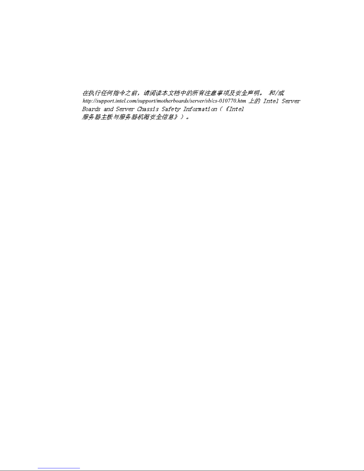
Read all caution and safety statements in this document before performing any of the
instructions. See also Intel Server Boards and Server Chassis Safety Information on the
®
Server Deployment Toolkit 2.0 CD and/or at http://support.intel.com/support/
Intel
motherboards/server/sb/cs-010770.htm.
Wichtige Sicherheitshinweise
Lesen Sie zunächst sämtliche Warnund Sicherheitshinweise in diesem Dokument, bevor
Sie eine der Anweisungen ausführen. Beachten Sie hierzu auch die Sicherheitshinweise zu
Intel-Serverplatinen und Servergehäusen auf der Intel
oder unter http://support.intel.com/support/motherboards/server/sb/cs-010770.htm.
®
Server Deployment Toolkit 2.0 CD
Consignes de sécurité
Lisez attention toutes les consignes de sécurité et les mises en garde indiquées dans ce
document avant de suivre toute instruction. Consultez Intel Server Boards and Server
Chassis Safety Information sur le Intel
rendez-vous sur le site http://support.intel.com/support/motherboards/server/sb/cs-
010770.htm.
®
Server Deployment Toolkit 2.0 CD ou bien
Instrucciones de seguridad importantes
Lea todas las declaraciones de seguridad y precaución de este documento antes de realizar
cualquiera de las instrucciones. Vea Intel Server Boards and Server Chassis Safety
Information en el Intel
support.intel.com/support/motherboards/server/sb/cs-010770.htm.
®
Server Deployment Toolkit 2.0 CD y/o en http://
Intel® Server System SC5400RA User’s Guide iii
Page 4
Warnings
重要安全指导
Heed safety instructions: Before working with your server product, whether you are
using this guide or any other resource as a reference, pay close attention to the safety
instructions. You must adhere to the assembly instructions in this guide to ensure and
maintain compliance with existing product certifications and approvals. Use only the
described, regulated components specified in this guide. Use of other products /
components will void the UL listing and other regulatory approvals of the product and
will most likely result in noncompliance with product regulations in the region(s) in which
the product is sold.
System power on/off: The power button DOES NOT turn off the system AC power. To
remove power from system, you must unplug the AC power cord from the wall outlet.
Make sure the AC power cord is unplugged before you open the chassis, add, or remove
any components.
Hazardous conditions, devices and cables: Hazardous electrical conditions may be
present on power, telephone, and communication cables. Turn off the server and
disconnect the power cord, telecommunications systems, networks, and modems attached
to the server before opening it. Otherwise, personal injury or equipment damage can
result.
Electrostatic discharge (ESD) and ESD protection: ESD can damage disk drives,
boards, and other parts. We recommend that you perform all procedures in this chapter
only at an ESD workstation. If one is not available, provide some ESD protection by
wearing an antistatic wrist strap attached to chassis ground any unpainted metal surface on
your server when handling parts.
ESD and handling boards: Always handle boards carefully. They can be extremely
sensitive to ESD. Hold boards only by their edges. After removing a board from its
protective wrapper or from the server, place the board component side up on a grounded,
static free surface. Use a conductive foam pad if available but not the board wrapper. Do
not slide board over any surface.
iv Intel® Server System SC5400RA User’s Guide
Page 5

Installing or removing jumpers: A jumper is a small plastic encased conductor that slips
over two jumper pins. Some jumpers have a small tab on top that you can grip with your
fingertips or with a pair of fine needle nosed pliers. If your jumpers do not have such a
tab, take care when using needle nosed pliers to remove or install a jumper; grip the
narrow sides of the jumper with the pliers, never the wide sides. Gripping the wide sides
can damage the contacts inside the jumper, causing intermittent problems with the
function controlled by that jumper. Take care to grip with, but not squeeze, the pliers or
other tool you use to remove a jumper, or you may bend or break the pins on the board.
Intel® Server System SC5400RA User’s Guide v
Page 6

vi Intel® Server System SC5400RA User’s Guide
Page 7

Preface
About this Manual
Thank you for purchasing and using the Intel® Server System SC5400RA.
This manual is written for system technicians who are responsible for troubleshooting,
upgrading, and repairing this server system. This document provides a brief overview of
the features of the server system, a list of accessories or other components you may need,
troubleshooting information, and instructions on how to add and replace components on
the Intel
support.intel.com/support/motherboards/server/SC5400RA/.
Manual Organization
Chapter 1 provides a brief overview of the Intel® Server System SC5400RA. In this
chapter, you will find a list of the server system features, photos of the product, and
product diagrams to help you identify components and their locations.
®
Server System SC5400RA. For the latest version of this manual, see http://
Chapter 2 provides instructions on adding and replacing components. Use this chapter for
step-by-step instructions and diagrams for installing or replacing components such as the
fans, power supply, drives, and other components.
Chapter 3 provides instructions on using the utilities that are shipped with the board or
that may be required to update the system. This includes how to navigate through the
BIOS Setup screens, how to perform a BIOS update, and how to reset the password or
CMOS. Information about the specific BIOS settings and screens is available in the
Technical Product Specification. See “Additional Information and Software” on page ix
for a link to the Technical Product Specification.
Chapter 4 provides technical reference information on cable routing, power supply
specifications, and system environment requirements.
At the back of this document, you will find appendices on safety, regulatory, "getting
help", and warranty information.
vii
Page 8

Product Contents, Order Options, and
Accessories
Your Intel® Server System SC5400RA ships with the following items:
• One Intel
• One 830-watt power supply, installed in the chassis
• One box of hardware components, referred to in this list as the "server system
hardware box"
• Fans, pre-installed in your server system
• One chassis intrusion switch and cable, installed in your server system
• Attention document, in the server system product box
• One Intel
system hardware box
• One USB cable, installed in the server system
• One IDE cable, in the hardware box
• One COM2 cable, in the hardware box
• Four 24-inch and two 34-inch SATA cables, in the hardware box
®
server board SC5400RA, installed in the chassis
®
Server System SC5400RA Quick Start User's Guide, in the server
• One accessory kit that contains screws and wire ties.
• One Intel
®
Server Deployment Toolkit 2.0 CD
• Two CD package of system management software:
—One Intel
—One Intel
In addition, you may need or want to purchase one or more of the following accessory
items for your server:
Processor, memory DIMMs, hard drive, floppy drive, CD-ROM or DVD-ROM drive,
RAID controller, operating system.
For information about which accessories, memory, processors, and third-party hardware
have been tested and can be used with your board, and for ordering information for Intel
products, see http://support.intel.com/support/motherboards/server/SC5400RA/
compat.htm.
®
System Management Software 1.5 CD
®
Deployment Assistant CD
viii Intel® Server System SC5400RA User’s Guide
Page 9

Additional Information and Software
If you need more information about this product or information about the accessories that
can be used with this server system, use the following resources. These files are available
at http://support.intel.com/support/motherboards/server/SC5400RA/.
Unless otherwise indicated in the table below, once on this Web page, type the document
or software name in the search field at the left side of the screen and select the option to
search "This Product."
For this information or
software
For in-depth technical
information about this
product, including BIOS
settings and chipset
information
If you just received this
product and need to install
it
For virtual system tours
and interactive repair
information
Accessories or other Intel
server products
Hardware (peripheral
boards, adapter cards) and
operating systems that
have been tested with this
product
For software to manage
your Intel
For diagnostics test
software
®
server
Use this Document or Software
®
Intel
Server System SC5400RA Technical Product Specification
Intel® Server System SC5400RA Quick Start User's Guide in the
product box
A link to the SMaRT Tool is available under "Other Resources" at the
right side of the screen at:
http://support.intel.com/support/motherboards/server/SC5400RA/
Spares and Configuration Guide
Tested Hardware Operating Systems List
®
Intel
System Management Software
Search for “Diagnostics”
Intel® Server System SC5400RA User’s Guide ix
Page 10

x Intel® Server System SC5400RA User’s Guide
Page 11

Contents
Safety Information ..................................................................................................... iii
Important Safety Instructions ........................................................................................ iii
Wichtige Sicherheitshinweise ....................................................................................... iii
Consignes de sécurité .................................................................................................. iii
Instrucciones de seguridad importantes ....................................................................... iii
Warnings ...................................................................................................................... iv
Preface .......................................................................................................................vii
About this Manual ........................................................................................................ vii
Manual Organization ................................................................................................... vii
Product Contents, Order Options, and Accessories ....................................................viii
Additional Information and Software ............................................................................. ix
Chapter 1: Server System Features .......................................................................... 1
Component Identification ...............................................................................................4
Front Control Panel ...................................................................................................5
®
Intel
Local Control Panel (optional component) ......................................................7
Back Panel Features .................................................................................................8
Peripheral Devices ..................................................................................................10
Server Board Connector and Header Locations .....................................................11
Configuration Jumpers ............................................................................................13
®
Intel
Light-Guided Diagnostics ..............................................................................15
®
Intel
Remote Management Module and RMM NIC Accessory ..................................17
Rack-mount Installation Options ..................................................................................17
Storage Device Options ...............................................................................................17
Hard Disk Drives .....................................................................................................18
Floppy / CD-ROM / DVD-ROM Slimline Carriers ....................................................18
Processor and Memory Requirements ........................................................................18
Processor ................................................................................................................18
Memory ...................................................................................................................19
Chapter 2: Hardware Installations and Upgrades .................................................23
Before You Begin ........................................................................................................23
Tools and Supplies Needed ....................................................................................23
System References .................................................................................................23
Removing and Installing the Chassis Cover ................................................................24
Removing the Chassis Cover .................................................................................24
Installing the Chassis Cover ...................................................................................25
Removing and Installing the Front Bezel .....................................................................26
Removing the Bezel Assembly (Pedestal Only) .....................................................26
Intel® Server System SC5400RA User’s Guide xi
Page 12

Installing the Front Bezel (Pedestal Only) .............................................................. 27
Installing and Removing Fixed Hard Drive(s) .............................................................. 28
Installing Fixed Hard Drive(s) ................................................................................. 28
Removing Fixed Hard Drive(s) ............................................................................... 33
Installing and Removing Hot-swap Drive(s) ................................................................ 38
Installing Hot-swap Drive(s) .................................................................................... 38
Removing Hot-swap Drive(s) .................................................................................. 40
Installing and Removing a Slimline USB Floppy/CD-ROM / DVD-ROM Drive Combo 42
Installing a Slimline USB Floppy / CD-ROM / DVD-ROM Slimline Kit .................... 42
Removing a Slimline USB Floppy / CD-ROM / DVD-ROM Combo Drive ............... 49
Installing and Removing a DVD-ROM or CD-ROM Drive ........................................... 51
Installing a DVD-ROM or CD-ROM Drive ............................................................... 51
Removing a DVD-ROM or CD-ROM Drive ............................................................. 53
Installing and Removing PCI Add-in Card(s) .............................................................. 54
Installing PCI Add-in Card(s) .................................................................................. 54
Removing PCI Add-in Card(s) ................................................................................ 58
Installing and Removing Memory ................................................................................ 60
Installing FBDIMMs ................................................................................................ 60
Removing FBDIMMs .............................................................................................. 66
Removing and Installing the Processor Air Duct ......................................................... 68
Removing the Processor Air Duct .......................................................................... 68
Installing the Processor Air Duct ............................................................................ 69
Installing or Removing a Processor ............................................................................ 70
Installing a Processor ............................................................................................. 70
Removing a Processor ........................................................................................... 74
Installing or Removing a Heatsink ............................................................................... 76
Installing a Heatsink ............................................................................................... 76
Removing a Heatsink ............................................................................................. 77
Installing and Removing the Intel
®
Remote Management Module and the Intel® RMM
NIC .................................................................................................................. 79
Installing the Intel
Removing the Intel
®
RMM and the Intel® RMM NIC ................................................ 79
®
RMM and the Intel® RMM NIC .............................................. 81
Replacing the Control Panel ....................................................................................... 83
Replacing a System Fan ............................................................................................. 84
Installing an Additional Hot-swap Power Supply Module ............................................ 85
Replacing a Hot-swap Power Supply .......................................................................... 86
Replacing the Power Distribution Board ..................................................................... 88
Replacing the CMOS Battery ...................................................................................... 97
Replacing the Server Board ........................................................................................ 99
Removing the Server Board ................................................................................... 99
Installing a Server Board ...................................................................................... 102
Chapter 3: System Utilities ....................................................................................105
Using the BIOS Setup Utility ..................................................................................... 105
xii Intel® Server System SC5400RA User’s Guide
Page 13

Starting Setup .......................................................................................................105
If You Cannot Access Setup .................................................................................105
Setup Menus .........................................................................................................106
Upgrading the BIOS ..................................................................................................107
Preparing for the Upgrade ....................................................................................108
Upgrading the BIOS ..............................................................................................108
Reverting to the Previous BIOS .................................................................................109
Clearing the Password ..............................................................................................110
Clearing the CMOS ...................................................................................................112
Chapter 4: Technical Reference ............................................................................ 113
Power Cable Routing to Fixed Drives ........................................................................113
Data Cable Routing to Fixed Drives ..........................................................................114
Power Supply Specifications .....................................................................................115
830-W Single Power Input Voltages .....................................................................115
830-W Single Power Supply Output Voltages ......................................................115
System Environmental Specifications .......................................................................116
Appendix A: Installation/Assembly Safety Instructions ..................................... 117
English .......................................................................................................................117
Deutsch .....................................................................................................................119
Français .....................................................................................................................122
Español ......................................................................................................................124
Italiano .......................................................................................................................126
Appendix B: Safety Information ............................................................................ 129
English .......................................................................................................................129
Server Safety Information .....................................................................................129
Safety Warnings and Cautions .............................................................................129
Intended Application Uses ....................................................................................130
Site Selection ........................................................................................................130
Equipment Handling Practices ..............................................................................130
Power and Electrical Warnings .............................................................................131
System Access Warnings .....................................................................................132
Rack Mount Warnings ...........................................................................................132
Electrostatic Discharge (ESD) ..............................................................................133
Other Hazards .......................................................................................................133
Sicherheitshinweise für den Server ......................................................................134
Sicherheitshinweise und Vorsichtsmaßnahmen ...................................................134
Zielbenutzer der Anwendung ................................................................................135
Standortauswahl ...................................................................................................135
Handhabung von Geräten .....................................................................................135
Warnungen zu Netzspannung und Elektrizität ......................................................136
Warnhinweise für den Systemzugang ..................................................................137
Warnhinweise für Racks .......................................................................................138
Intel® Server System SC5400RA User’s Guide xiii
Page 14

Elektrostatische Entladungen (ESD) .................................................................... 138
Andere Gefahren .................................................................................................. 139
Français .................................................................................................................... 140
Consignes de sécurité sur le serveur ................................................................... 140
Sécurité: avertissements et mises en garde ......................................................... 140
Domaines d’utilisation prévus ............................................................................... 141
Sélection d’un emplacement ................................................................................ 141
Pratiques de manipulation de l’équipement .......................................................... 141
Alimentation et avertissements en matière d’électricité ........................................ 142
Avertissements sur l’accès au système ................................................................ 143
Avertissements sur le montage en rack ............................................................... 143
Décharges électrostatiques (ESD) ....................................................................... 144
Autres risques ....................................................................................................... 144
Español ..................................................................................................................... 145
Información de seguridad del servidor ................................................................. 145
Advertencias y precauciones sobre seguridad ..................................................... 145
Aplicaciones y usos previstos ............................................................................... 146
Selección de la ubicación ..................................................................................... 146
Manipulación del equipo ....................................................................................... 147
Advertencias de alimentación y eléctricas ............................................................ 147
Advertencias el acceso al sistema ....................................................................... 148
Advertencias sobre el montaje en bastidor .......................................................... 149
Descarga electrostática (ESD) ............................................................................. 149
Appendix C: Regulatory and Compliance Information .......................................157
Product Regulatory Compliance ............................................................................... 157
Product Safety Compliance .................................................................................. 157
Product Regulatory Compliance References ....................................................... 158
Electromagnetic Compatibility Notices ...................................................................... 161
FCC Verification Statement (USA) ....................................................................... 161
Industry Canada (ICES-003) ................................................................................ 162
Europe (CE Declaration of Conformity) ................................................................ 162
VCCI (Japan) ........................................................................................................ 162
BSMI (Taiwan) ...................................................................................................... 162
Korean Compliance (RRL) ................................................................................... 163
CNCA (CCC-China) .............................................................................................. 163
Product Ecology Compliance ............................................................................... 163
Other Markings ..................................................................................................... 166
Regulated Specified Components ........................................................................ 167
End-of-Life / Product Recycling ................................................................................. 168
Appendix D: Getting Help ......................................................................................169
World Wide Web ....................................................................................................... 169
Telephone ................................................................................................................. 169
xiv Intel® Server System SC5400RA User’s Guide
Page 15

Appendix E: Warranty ............................................................................................173
Limited Warranty for Intel® Server System Subassembly Products ..........................173
Extent of Limited Warranty ........................................................................................174
Warranty Limitations and Exclusions .........................................................................174
Limitations of Liability ............................................................................................174
How to Obtain Warranty Service ...............................................................................175
Telephone Support ...............................................................................................175
Returning a Defective Product ..............................................................................175
Intel® Server System SC5400RA User’s Guide xv
Page 16

xvi Intel® Server System SC5400RA User’s Guide
Page 17

List of Figures
Figure 1. Intel® Server System SC5400RA............................................................................... 1
Figure 2. Component Locations ................................................................................................ 4
Figure 3. Front Control Panel.................................................................................................... 5
Figure 4. Intel
Figure 5. Server System Back................................................................................................... 8
Figure 6. Back Panel Connectors and LEDs............................................................................. 9
Figure 7. Optional Peripherals................................................................................................. 10
Figure 8. Server Board Connector and Component Locations ............................................... 12
Figure 9. Configuration Jumpers............................................................................................. 14
Figure 10. System LEDs ......................................................................................................... 16
Figure 11. DIMM Sockets........................................................................................................ 20
Figure 12. Removing the Chassis Cover................................................................................. 24
Figure 13. Installing the Chassis Cover................................................................................... 25
Figure 14. Removing the Front Bezel...................................................................................... 26
Figure 15. Installing the Front Bezel........................................................................................ 27
Figure 16. Removing Six-drive Fixed Drive Cage ................................................................... 28
Figure 17. Unlocking and Opening Upper Door of Fixed Drive Cage ..................................... 29
Figure 18. Opening Lower Door of Fixed Drive Cage ............................................................. 29
Figure 19. Removing Slides from Drive Cage......................................................................... 30
Figure 20. Attaching Device Slides to Hard Drive................................................................... 30
Figure 21. Inserting Drive/Slide Assembly into Drive Cage..................................................... 31
Figure 22. Closing Lower Door of Fixed Drive Cage............................................................... 31
Figure 23. Closing Upper Door of Fixed Drive Cage............................................................... 32
Figure 24. Tightening Captive Screw ...................................................................................... 32
Figure 25. Removing Six-drive Fixed Drive Cage ................................................................... 33
Figure 26. Unlocking and Opening Upper Door of Fixed Drive Cage ..................................... 34
Figure 27. Opening Lower Door of Fixed Drive Cage ............................................................. 34
Figure 28. Removing Drive/Slide Assembly from Drive Cage................................................. 34
Figure 29. Inserting Empty Device Slides into Drive Cage...................................................... 35
Figure 30. Closing Lower Door of Fixed Drive Cage............................................................... 35
Figure 31. Closing Upper Door of Fixed Drive Cage............................................................... 36
Figure 32. Tightening Thumb Screw ....................................................................................... 37
Figure 33. Removing Drive Carrier from Hot-swap Cage........................................................ 38
Figure 34. Removing Plastic Air Baffle.................................................................................... 38
Figure 35. Securing Hard Drive to Drive Carrier ..................................................................... 39
Figure 36. Inserting Drive Carrier into Hot Swap Cage........................................................... 39
Figure 37. Releasing Drive Carrier from Hot-swap Cage........................................................ 40
Figure 38. Removing Hard Drive from Drive Carrier ............................................................... 40
Figure 39. Installing Plastic Air Baffle in Drive Carrier............................................................. 41
Figure 40. Inserting Drive Carrier into Hot Swap Cage........................................................... 41
Figure 41. Removing Drive Cage from Drive Bay................................................................... 42
Figure 42. Removing Cage Top from Drive Cage................................................................... 43
®
Local Control Panel Features........................................................................... 7
Intel® Server System SC5400RA User’s Guide xvii
Page 18

Figure 43. Inserting Slimline Floppy Drive into Drive Cage .................................................... 43
Figure 44. Securing Slimline Floppy Drive to Drive Cage....................................................... 44
Figure 45. Attaching Backplane to Slimline CD-ROM / DVD-ROM Drive............................... 44
Figure 46. Securing Slimline CD-ROM Drive or Slimline DVD-ROM Drive to Drive Cage ..... 45
Figure 47. Installing the Cage Top to the Drive Cage............................................................. 45
Figure 48. Inserting Drive Cage into Drive Bay....................................................................... 46
Figure 49. Attaching Drive Cage to Drive Bay ........................................................................ 46
Figure 50. Removing EMI Shield/Slide Assembly................................................................... 47
Figure 51. Attaching Drive Rails to Slimline Drive Assembly.................................................. 47
Figure 52. Inserting Slimline Drive Assembly ......................................................................... 47
Figure 53. Cable Connections ................................................................................................ 48
Figure 54. Removing Slimline DVD-ROM / CD-ROM Drive Assembly from Upper Device Bay..
49
Figure 55. Installing Empty EMI Shield/Slide Assembly ......................................................... 50
Figure 56. Removing EMI Shield/Slide Assembly from Upper Device Bay ............................ 51
Figure 57. Attaching Slides to a DVD-ROM or CD-ROM Drive .............................................. 52
Figure 58. Removing DVD-ROM / CD-ROM Drive Assembly from Upper Device Bay .......... 53
Figure 59. Reinserting Empty EMI Shield/Slide Assembly ..................................................... 53
Figure 60. Preparing System for Addition of PCI Add-in Card................................................ 55
Figure 61. Installing Add-in Card ............................................................................................ 56
Figure 62. Reinstalling PCI Add-in Card Retainer .................................................................. 57
Figure 63. Preparing System for Removal of PCI Add-in Card............................................... 59
Figure 64. Opening DIMM Cage............................................................................................. 61
Figure 65. Removing Memory Riser Cards............................................................................. 62
Figure 66. DIMM Sockets ....................................................................................................... 63
Figure 67. Installing FBDIMMs................................................................................................ 64
Figure 68. Inserting Memory Riser Cards............................................................................... 65
Figure 69. Opening DIMM Cage............................................................................................. 66
Figure 70. Removing Memory Riser Cards............................................................................. 67
Figure 71. Removing the Processor Air Duct.......................................................................... 68
Figure 72. Installing the Air Duct............................................................................................. 69
Figure 73. Locating Processor Sockets / Heatsinks ............................................................... 71
Figure 74. Removing Heatsink................................................................................................ 72
Figure 75. Opening Processor Socket Lever.......................................................................... 72
Figure 76. Opening Load Plate............................................................................................... 72
Figure 77. Removing Protective Cover from Load Plate......................................................... 73
Figure 78. Setting Processor in Place..................................................................................... 73
Figure 79. Opening Processor Socket Lever.......................................................................... 74
Figure 80. Opening Load Plate............................................................................................... 74
Figure 81. Removing Processor from Socket ......................................................................... 75
Figure 82. Installing Protective Cover onto Load Plate........................................................... 75
Figure 83. Applying Thermal Grease...................................................................................... 76
Figure 84. Installing a Heatsink............................................................................................... 77
Figure 85. Preparing System for Addition of Intel
Figure 86. Installing Intel
Figure 87. Installing the Intel
Figure 88. Removing the Intel
®
RMM NIC...................................................................................... 80
®
Remote Management Module ................................................ 81
®
RMM NIC.............................................................................. 82
®
RMM NIC ................................................ 79
xviii Intel® Server System SC5400RA User’s Guide
Page 19

Figure 89. Removing the Intel® Remote Managemrnt Module ............................................... 82
Figure 90. Removing a Fixed Fan........................................................................................... 84
Figure 91. Removing the Power Supply Filler Panel............................................................... 85
Figure 92. Installing an Additional Hot-swap Power Supply Module....................................... 86
Figure 93. Removing a Hot-swap Power Supply..................................................................... 86
Figure 94. Installing Hot Swap Power Supply ......................................................................... 87
Figure 95. Removing Hot Swap Power Supply ....................................................................... 88
Figure 96. Detaching Center Divider....................................................................................... 89
Figure 97. Removing Center Divider....................................................................................... 90
Figure 98. Detaching Power Distribution Board ...................................................................... 91
Figure 99. Removing Power Distribution Board ...................................................................... 92
Figure 100. Inserting Power Distribution Board....................................................................... 93
Figure 101. Securing Power Distribution Board to Power Supply Cage ................................. 94
Figure 102. Re-installing Center Divider ................................................................................. 95
Figure 103. Securing Center Divider....................................................................................... 96
Figure 104. Installing Hot Swap Power Supply ....................................................................... 96
Figure 105. Locating and Removing the CMOS Battery ......................................................... 98
Figure 106. Opening Memory Riser Cage............................................................................... 99
Figure 107. Removing Memory Riser Cards......................................................................... 100
Figure 108. Removing Memory Riser Cage.......................................................................... 101
Figure 109. Installing Memory Riser Cage............................................................................ 102
Figure 110. BIOS Bank Select Jumper in Force Lower Bank Position.................................. 109
Figure 111. Password Clear Jumper in Clear Password Position......................................... 111
Figure 112. CMOS Clear Jumper in the Clear CMOS Position............................................. 112
Figure 113. Routing Power Cables to Fixed Drives .............................................................. 113
Figure 114. Routing SATA Data Cables................................................................................ 114
Intel® Server System SC5400RA User’s Guide xix
Page 20

xx Intel® Server System SC5400RA User’s Guide
Page 21

List of Tables
Table 1. Server System Features ..............................................................................................2
Table 2. Front Control Panel LED Descriptions ........................................................................6
Table 3. NIC LEDs ....................................................................................................................9
Table 4. Setup Menu Key Use ..............................................................................................106
Table 5. 830-W Power Supply Output Capability ..................................................................115
Table 6. Environmental Specifications ..................................................................................116
Table 7. Product Regulatory Compliance Markings ..............................................................158
Table 8. Product Ecology Compliance Markings ...................................................................164
Table 9. Other Markings ........................................................................................................166
Intel® Server System SC5400RA User’s Guide xxi
Page 22

xxii Intel® Server System SC5400RA User’s Guide
Page 23
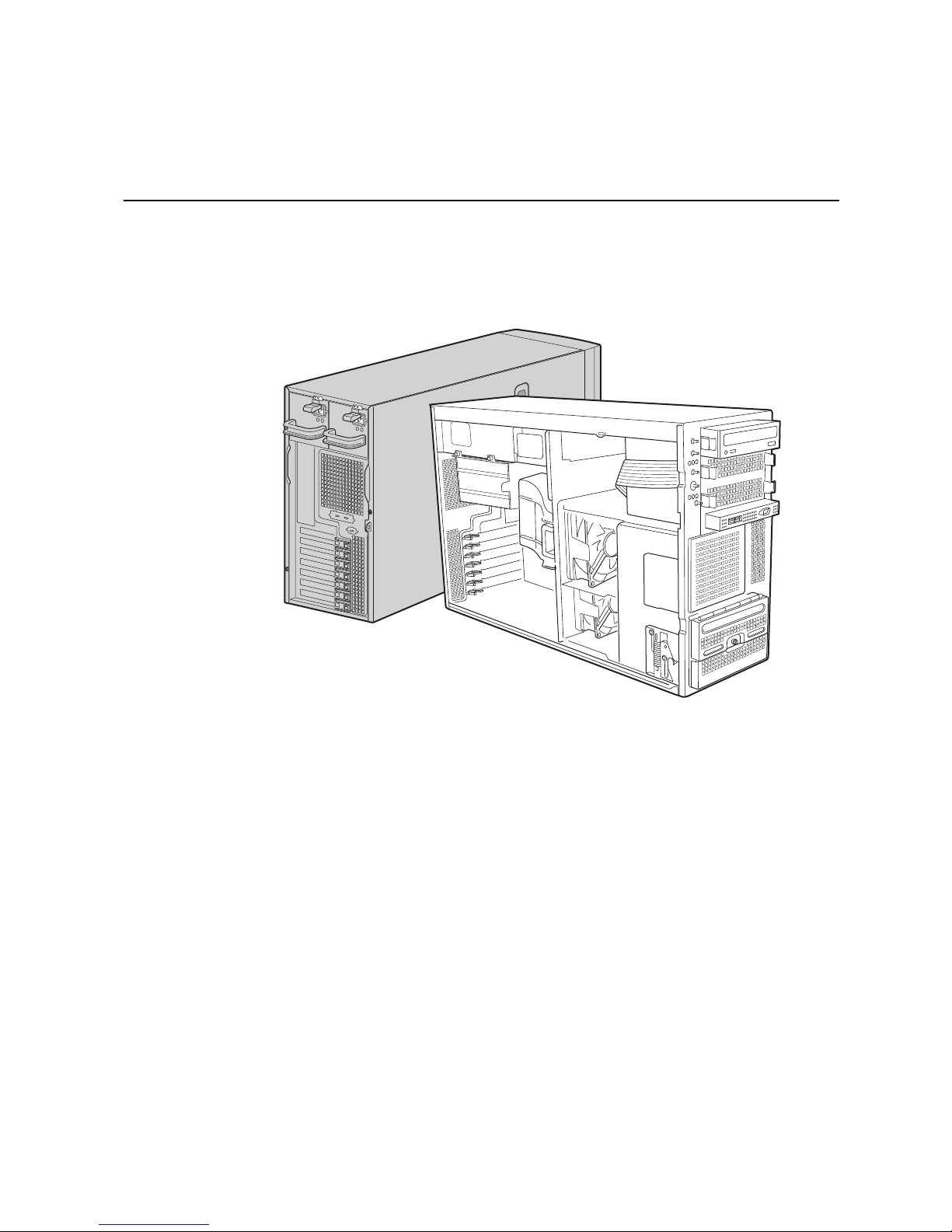
1 Server System Features
This chapter briefly describes the main features of the Intel® Server System SC5400RA.
This chapter provides a list of the server system features, and diagrams that show the
location of important components and connections in the server system.
AF001483
Figure 1. Intel
Intel® Server System SC5400RA User’s Guide 1
®
Server System SC5400RA
Page 24

The table below summarizes the features of the Intel® Server System SC5400RA.
Table 1. Server System Features
Feature Description
Dimensions • 16.6 inches high (pedestal: 17 inches)
• 8.6 inches wide
• 27.4 inches deep (pedestal: 28.4 inches)
• 36.2 kilograms
Hard Drives One fixed drive bay for up to six fixed SATA drives.
Optional hot swap drive bay:
• Ultra ATA-100 support: One IDE channel that is capable of
supporting up to two drives
• Six SATA connectors at 3 GB/s
Peripherals Three multi-mount 5.25-inch peripheral bays
RAID support Six-port SATA with BIOS-enabled embedded RAID 0, 1, and 10 with
Control Panel (dependent
on option selected)
LEDs and displays
(dependent on option
selected)
optional RAID 5 support provided by the Intel
AXXRAKSW5.
• Front Control Panel
®
• Intel
With Front Control Panel:
Local Control Panel (optional)
• NIC1 Activity
®
RAID Activation Key
• NIC2 Activity
• Power / Sleep
• System Status
• System Identification
• Hard Drive Activity
Power Supply One 830-W power supply is standard. Upgradable to 830-W
USB 2.0
redundant power by adding a second power supply module.
• Two front panel USB ports with Front Control Panel
• Four back panel USB ports
• One internal USB port on the server board
Video
• On-board ATI* ES1000 video controller with 16-MB DDR
SDRAM
• One rear panel video port
Processor support Support for up to two Dual-Core Intel
System memory support
5100 sequence with a 677-, 1066-, or 1333-MHz front side bus or up
to two Quad-Core Intel
MHz front side bus
• DDR2-533 and DDR2-667 FBDIMM sockets that support a total
of 64 MB memory
®
Xeon® processors with a 1066-, or 1333-
®
Xeon® processor 5000 or
• Quad-channel memory architecture
®
Intel
S5000P chipset • Intel® 6321ESB I/O Controller Hub
• Intel
®
5000P Memory Controller Hub
2 Intel® Server System SC5400RA User’s Guide
Page 25

Feature Description
Cooling Two fixed, non-redundant chassis fans:
• One 120-mm fan
• One 92-mm fan
Add-in card slots Six expansion slots:
• One PCI Express* x4 slot
• Three PCI Express* x8 slots
• One 64-bit 100-MHz PCI-X* slot
• One 64-bit 100- / 133-MHz PCI-X slot
I/O control support External connections:
• PS/2* ports for keyboard and mouse
• DB9 serial port A connection
• One DH10 serial port B connector
• Two RJ45 NIC connectors for 10/100/1000 Mb connections:
®
Dual GbE with Intel
I/O Acceleration Technology
• Four USB 2.0 ports at the back of the board
Internal connections:
• One 9-pin USB header that supports two external USB 2.0 ports
• One internal USB port that supports a peripheral, such as a
floppy drive
• One DH10 serial port B header
• One ATA-100 40-pin connector
• One SSI-compliant 24-pin front control panel header
Management support • Support for the Intel® Local Control Panel (optional component
sold separately)
• Support for the Intel
component sold separately)
• Support for Intel
®
• Intel
Light-Guided Diagnostics on field replaceable units
®
Remote Management Module (optional
®
System Management software
Intel® Server System SC5400RA User’s Guide 3
Page 26
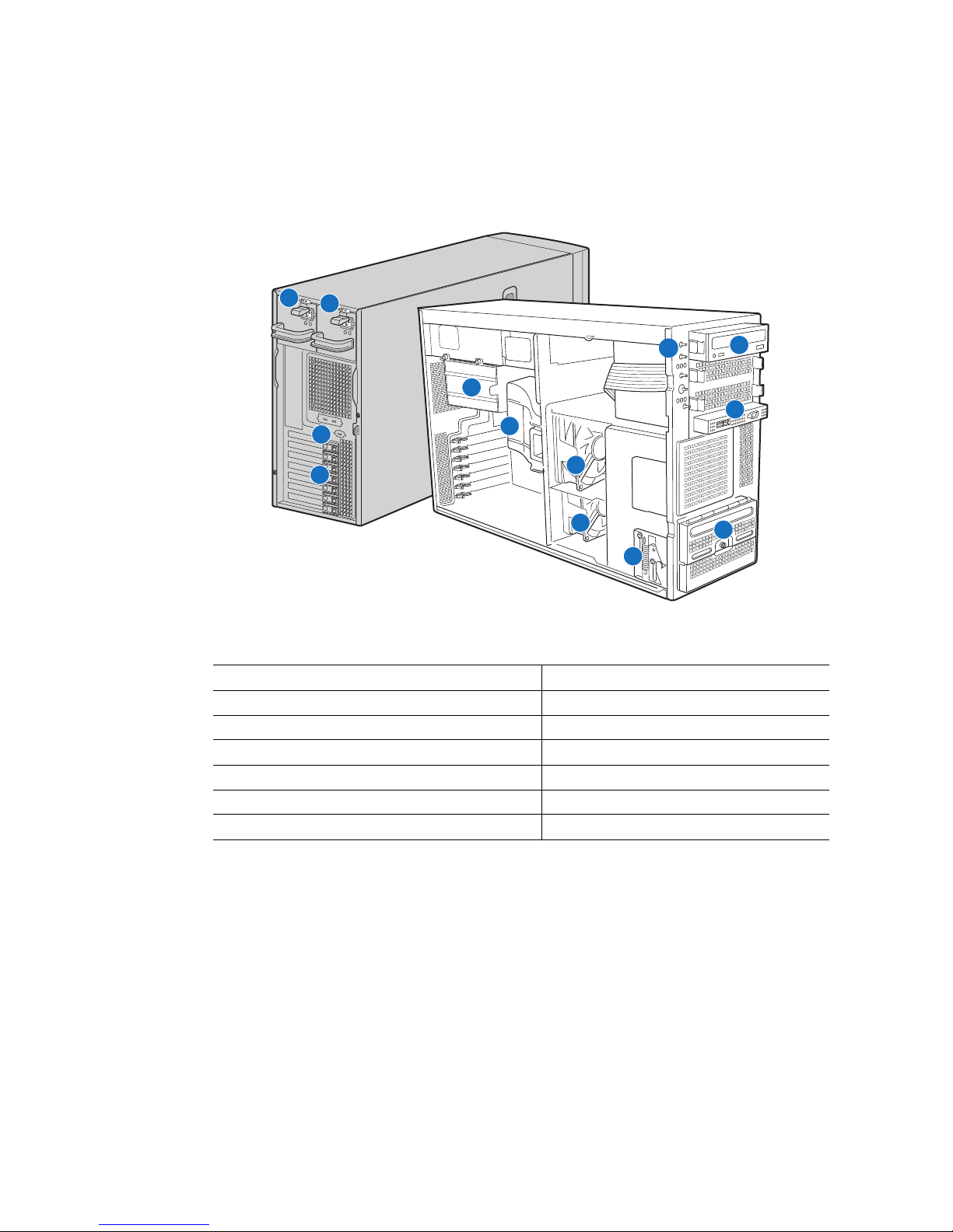
Component Identification
1
2
10
11
5
12
3
4
6
7
8
13
9
AF001484
1. Hot swap power supply 8. Fixed fan - small
2. Hot swap power supply (optional) 9. Hard drive cage release mechanism
3. Rear Serial B connector 10. Front panel controls
4. PCI add-in card panel 11. 5.25-inch device bays (three)
5. Memory cage 12. Front panel USB / Serial B connectors
6. Processor air duct 13. Six-drive fixed drive cage
7. Fixed fan - large
4 Intel® Server System SC5400RA User’s Guide
Figure 2. Component Locations
Page 27
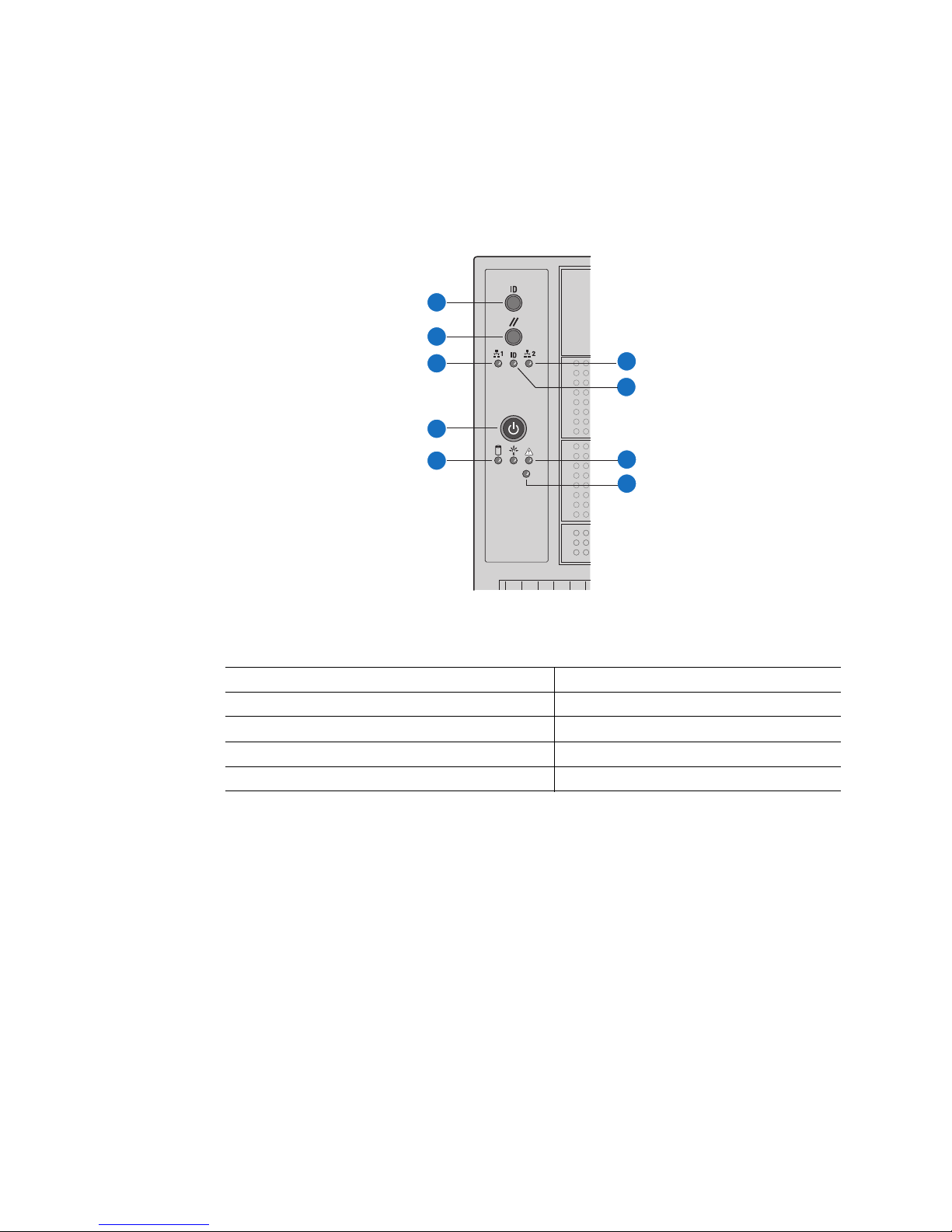
Front Control Panel
The following figure shows the features available on the front control panel. The Intel®
Local Control Panel is optional.
A
B
C
F
G
D
E
H
I
TP00701
A. ID Toggle Switch F. NIC2 Activity LED (green)
B. Reset Button G. ID LED (blue)
C. NIC 1 Activity LED (green) H. Status LED (bi-color)
D. Power Button I. NMI Button
E. Hard Drive Activity LED (green)
Figure 3. Front Control Panel
Intel® Server System SC5400RA User’s Guide 5
Page 28
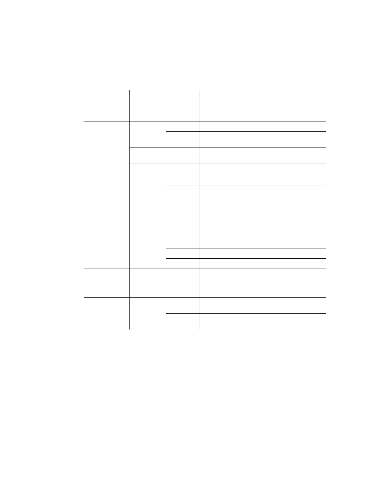
Descriptions of the front control panel LEDs are listed in the following table.
Table 2. Front Control Panel LED Descriptions
LED Name Color Condition Description
Power LED Green On Power on
Off Power off
Status Green On System ready
Blink System ready, but degraded: some CPU fault,
DIMM killed
Green/Blink
Amber
Amber On Critical alarm: critical power module failure, critical
Hard drive
activity
NIC1 activity Green On Linked
NIC2 activity Green On Linked
ID LED Blue Blink Server identification; toggled by ID button or
Green Blink Hard drive activity
Blink Condition during BMC reset.
fan failure, voltage (power supply), voltage and
thermal fault
Blink Non-critical failure: redundant fan failure,
redundant power failure, non-critical power and
voltage
Off System not ready: POST error/NMI event/PCI or
terminator missing
Blink LAN activity
Off Idle
Blink LAN activity
Off Idle
software
Off Server identification; toggled by ID button or
software
6 Intel® Server System SC5400RA User’s Guide
Page 29
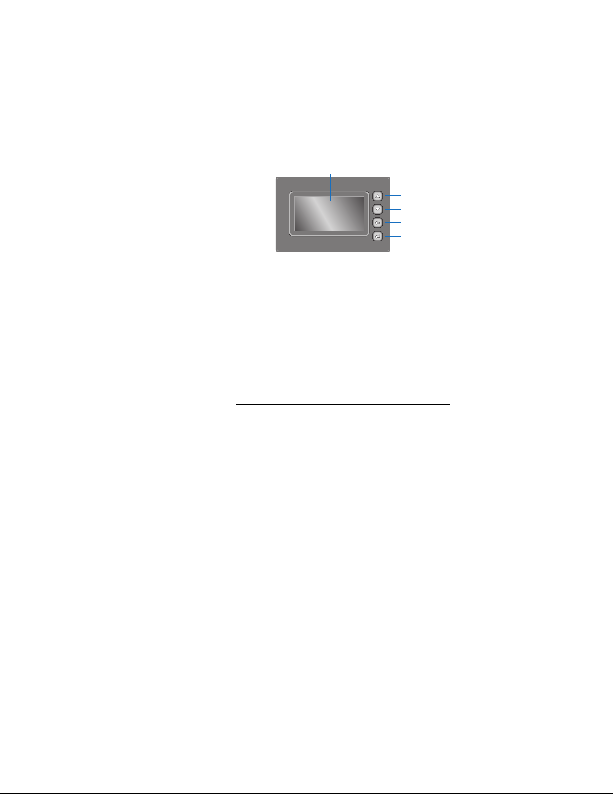
Intel® Local Control Panel (optional component)
The following figure shows the features available on the Intel® Local Control Panel. The
Intel Local Control Panel is optional.
A
B
C
D
E
AF000955
Callout Function
A. LCD display (variable content)
B. LCD up navigation button
C. LCD down navigation button
D. LCD backup level navigation button
E. LCD command enter button
Figure 4. Intel
®
Local Control Panel Features
Intel® Server System SC5400RA User’s Guide 7
Page 30
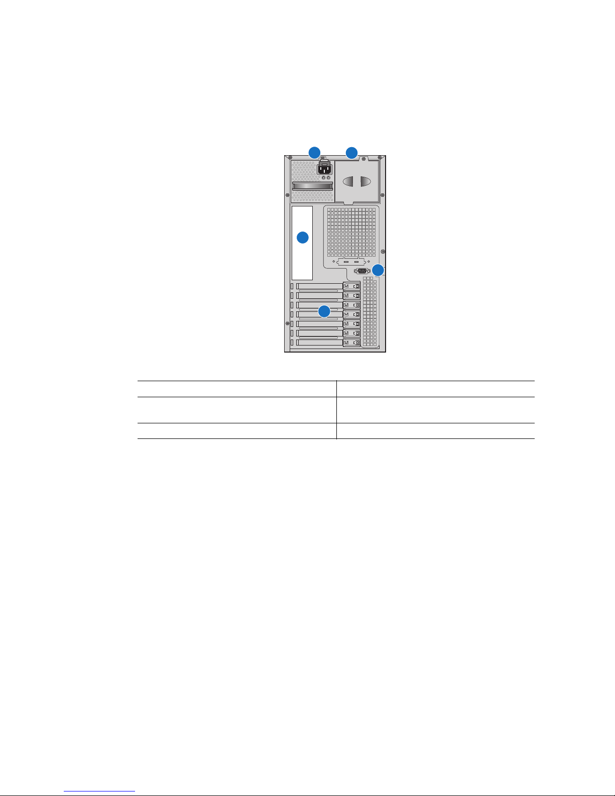
Back Panel Features
A
B
C
E
D
AF001485
A. Power supply D. PCI card area
B. Location for installing optional redundant
power supply
C. I/O Ports. See Figure 6 on page 9
E. Rear Serial B Connector (optional)
Figure 5. Server System Back
The diagram and table show the back panel connectors and LEDs. For information about
the LEDs, see “Intel
8 Intel® Server System SC5400RA User’s Guide
®
Light-Guided Diagnostics” on page 15.
Page 31

C E G
A H I JB D F
A. Mouse (top), Keyboard (bottom) F. Bit 1 LED (POST LED)
B. Status LED G. LSB LED (POST LED)
C. ID LED H. Serial A (top), Video (bottom)
D. MSB LED (POST LED) I. NIC1 (top), two USB (bottom)
E. Bit 2 LED (POST LED) J. NIC 2 (top), two USB (bottom)
Figure 6. Back Panel Connectors and LEDs
The NIC LEDs at the right and left of each NIC provide the following information.
Table 3. NIC LEDs
LED LED State Description
Left Off No network connection is in place
AF000421
Right Off 10 Mbps connection (if left LED is on or blinking)
Intel® Server System SC5400RA User’s Guide 9
Solid green Active network connection is in place
Blinking green Transmit / receive activity is occurring
Solid green 100 Mbps connection
Solid amber 1000 Mbps connection
Page 32

Peripheral Devices
The server system provides locations and hardware for installing hard drives, a floppy
drive, a CD-ROM drive, or a DVD-ROM drive. The drives must be purchased separately.
The following figure shows the available options.
A
B
C
E
A. Slimline floppy drive / DVD-ROM drive / CD-ROM drive
B. Optical or floppy drive bay
C. Optical or floppy drive bay
D. Hard drive cage for six hard drives. Can be replaced with 6-drive
hot-swap drive cage.
E. Release mechanism for hard drive cage
D
AF001510
Figure 7. Optional Peripherals
10 Intel® Server System SC5400RA User’s Guide
Page 33

Server Board Connector and Header Locations
I
A B DGFEC
J
H
K
L
OO
NN
MM
LL
KK
JJ
HH
GG
FF
EE
DD
M
N
O
P
II
Q
R
S
CC YAA
ZBB
XWV
U
T
AF001418
A. PCI-X* 64-bit, 100-MHz
slot 1
B. PCI-X 64-bit, 100-/133-MHz
slot 2
C. PCI Express* x4 slot 3 Q. Processor 1 socket EE. SATA 0
D. RMM NIC connector R. Processor 2 socket FF. SATA 1
E. PCI Express x8 slot 4 S. System fan 4 header GG. SATA 2
F. PCI Express x8 slot 5 T. System fan 3 header HH. SATA 3
G. PCI Express x8 slot 6 U. IPMB connector II. SATA 4
H. CMOS battery V. System fan 2 header JJ. SATA 5
I. P12V4 connector W. System fan 1 header KK. USB port
Intel® Server System SC5400RA User’s Guide 11
O. Auxiliary power signal
connector
P. DIMM riser sockets (see
Figure 11 on page 20)
CC. Hot-swap backplane B
header
DD. Hot-swap backplane A
header
Page 34

J. RMM connector (connector
for Intel
®
Remote
Management Module)
X. Processor power connector LL. Front control panel header
K. Back panel I/O ports (see
Y. USB header MM. SATA_Key: SATA RAID 5
Figure 6 on page 9)
L. Diagnostic and Identify
LEDs (see “Intel
®
Light-
Z. IDE connector NN. Serial B / emergency
Guided Diagnostics” on
page 15)
M. DIMM LEDs (see “Intel
Light-Guided Diagnostics”
®
AA. Enclosure management
SATA SGPIO header
on page 15)
N. Main power connector BB. Intel
header
Figure 8. Server Board Connector and Component Locations
®
Local Control Panel
key connector
management port header
OO. Chassis intrusion header
12 Intel® Server System SC5400RA User’s Guide
Page 35

Configuration Jumpers
BIOS Bank Select
Bank 0
Normal
Operation
J1C3
CMOS Clear
Disable
Enable
J1D1
Password Clear
Protect
Clear
J1D2
BMC Force Update
Disable
Enable
J1E3
2
3
2
3
2
3
2
3
AF001419
Jumper Name Pins What Happens at System Reset
BIOS Bank Select
(J1C3)
1 - 2 Bank 0: Boot to an alternate BIOS.
2 - 3 Boot from the standard BIOS. These pins should be
jumpered for normal operation.
CMOS Clear
(J1D1)
1 - 2 Protect CMOS: these pins should be jumpered for normal
operation.
2 - 3 Erase CMOS: If these pins are jumpered for 5 to 10
seconds, the CMOS settings will be cleared on the next
server reset. These pins should not be jumpered for
normal operation.
To clear the CMOS: Power down the server, leaving AC
power connected. Place the jumper on pins 2 - 3 for 5 to
10 seconds. Move the jumper back to pins 1 - 2. Power on
the server.
Intel® Server System SC5400RA User’s Guide 13
Page 36

Jumper Name Pins What Happens at System Reset
Password Clear
(J1D2)
BMC Force Update
(J1E3)
1 - 2 Protect password: These pins should be jumpered for
normal operation.
2 - 3 Erase password: If these pins are jumpered for 5 to 10
seconds, the password will be cleared on the next server
reset. These pins should not be jumpered for normal
operation.
To use this jumper to reset the password: Power down the
server. Place the jumper on pins 2 - 3. Power on the
server and wait 5 to 10 seconds. Power down the server.
Move the jumper back to pins 1 - 2. Power on the server.
1 - 2 Disable force update: These pins should be jumpered for
normal operation.
2 - 3 Enable force update: Jumpering these pins forces a BMC
update.
Figure 9. Configuration Jumpers
14 Intel® Server System SC5400RA User’s Guide
Page 37

Intel® Light-Guided Diagnostics
The server board contains diagnostic LEDs to help you identify failed and failing
components and to help you identify the server from among several servers. Except for the
ID LED, the status LED, and the +5-volt standby LED, the LEDs turn on (amber) only if a
failure occurs.
JK
A1 C1
A2
A3
A4
B1
B2
B3
B4
C2
C3
C4
D1
D2
D3
D4
B
A
C
D
E
F
G
H
I
Callout LED Function
A. LSB LED POST LED. The sequence of lit POST LEDs is used
B. Bit 1 LED POST LED. The sequence of lit POST LEDs is used
Intel® Server System SC5400RA User’s Guide 15
AF001420
to identify specific errors that might occur during the
boot process. See the appendix of the Technical
Product Specification for a description of how to read
these LEDs.
to identify specific errors that might occur during the
boot process. See the appendix of the Technical
Product Specification for a description of how to read
these LEDs.
Page 38

Callout LED Function
C. Bit 2 LED POST LED. The sequence of lit POST LEDs is used
to identify specific errors that might occur during the
boot process. See the appendix of the Technical
Product Specification for a description of how to read
these LEDs.
D. MSB LED POST LED. The sequence of lit POST LEDs is used
to identify specific errors that might occur during the
boot process. See the appendix of the Technical
Product Specification for a description of how to read
these LEDs.
E. ID LED This LED can be turned on and off either by pressing
a server system button or by using system
management software. This LED is useful when the
system is grouped with several systems, such as in a
rack, and you need to easily find the system to
perform maintenance on it.
F. Status LED The status LED indicates whether a system is
operating correctly, has experienced a minor fault, or
a major system error. For details about this LED, see
the Technical Product Specification.
G. +5-volt standby LED This LED is green whenever AC power is applied to
the system. The system does not need to be
powered on in order for this LED to be on.
H. Processor 2 fault LED This LED indicates a fault has occurred with the
processor installed in socket CPU_2 socket. Replace
the faulty processor.
I. Processor 1 fault LED This LED indicates a fault has occurred with the
processor installed in socket CPU_1 socket. Replace
the faulty processor.
J. DIMM riser card 1 fault
LEDs
K. DIMM riser card 2 fault
LEDs
This LED indicates a fault has occurred with the
corresponding DIMM in DIMM riser card 1. Replace
the failed DIMM. See Figure 11 on page 20 to locate
the DIMM sockets.
This LED indicates a fault has occurred with the
corresponding DIMM in DIMM riser card 2. Replace
the failed DIMM. See Figure 11 on page 20 to locate
the DIMM sockets.
Figure 10. System LEDs
16 Intel® Server System SC5400RA User’s Guide
Page 39

Intel® Remote Management Module and RMM
NIC Accessory
The Intel® Remote Management Module and the RMM NIC is an optional accessory kit.
These components plug into connectors on the server board and act as components of the
server board, not as separate products. These two components must be installed together.
These components provide a way to view and operate the server remotely, in real-time.
Keyboard, video, and mouse control (KVM) is redirected to a managing system. This
provides remote control. USB media redirection allows you to use a USB device
anywhere on the network as if it was installed on the managed server. For example, you
can insert a CD-ROM disk in a workstation CD-ROM drive and the managed server will
view it as its own CD-ROM drive.
®
For installation instructions, see “Installing and Removing the Intel
Management Module and the Intel
®
RMM NIC” on page 79.
Remote
Rack-mount Installation Options
Your Intel® Server System SC5400RA can be mounted into a rack. Intel provides a toolless rail kit and a cable management arm to mount this server system into a rack. When
installing the server system into a rack, Intel recommends you install systems from the
bottom of the rack to the top. In other words, install the first system in the rack into the
bottom position of the rack, the second system in the second position from the bottom, and
so on. Instructions for installing your server system into a rack are included in the rail kit.
The order numbers are as follows:
• Tool-less Rail Kit: ARIGRACK
• Cable Management Arm: AXXCMA3U7U (requires the tool-less rail kit,
ARIGRACK)
Storage Device Options
The Intel® Server System SC5400RA supports the following drive options:
• Optical hard disk drives
• Six SATA ports at 3 GB/s
• Parallel ATA (IDE): The server board includes one IDE connector.
Intel® Server System SC5400RA User’s Guide 17
Page 40

Hard Disk Drives
One drive cage that supports six cabled drives ships with the server system. An optional
hot-swap drive cage can be installed to replace the six-drive fixed drive cage. For
instructions on installing hard drives, see “Installing and Removing Hot-swap Drive(s)”
on page 38.
Note: Drives can consume up to 17 watts of power each. Drives must be specified to run at a
maximum ambient temperature of 45
The Intel
Information and Software” on page ix for an Internet link to a list of supported hardware.
®
Server System SC5400RA does not support all hard drives. See “Additional
o
C.
Floppy / CD-ROM / DVD-ROM Slimline Carriers
For installation instructions on installing a floppy drive see “Installing and Removing a
Slimline USB Floppy/CD-ROM / DVD-ROM Drive Combo” on page 42. For installation
instructions on installing a CD-ROM drive or DVD-ROM drive, see “Installing and
Removing a DVD-ROM or CD-ROM Drive” on page 51.
To use one of the slimline drives provided by Intel, use the following order codes:
• Slimline CD-ROM Drive: AXXSCD
• Slimline DVD/CDR Drive: AXXDVDCDR
• Slimline Floppy Drive: AXXCDUSBFDBRK
®
Note: The Intel
DVD-ROM hard drives. See “Additional Information and Software” on page ix for an
Internet link to a list of supported hardware. Intel provides accessory kits for these drives.
Server System SC5400RA does not support all slimline floppy, CD-ROM or
Processor and Memory Requirements
To avoid integration difficulties and possible board damage, your system must meet the
requirements outlined below. For a list of qualified components, see the links under
“Additional Information and Software” on page ix.
Processor
One or two Multi-Core Intel®Xeon® processors 5000, 5100, or 5300 sequence. For a list
of supported processors, see the links under “Additional Information and Software” on
page ix.
18 Intel® Server System SC5400RA User’s Guide
Page 41

Memory
The Intel® Server System SC5400RA provides 16 DIMM sockets in four channels:
• Channel A is in the left riser card, nearest to the center of the server board. This
channel consists of
— DIMM_A1 (must be populated for minimum configuration)
—DIMM_A2
—DIMM_A3
—DIMM_A4
• Channel B is in the left riser card, nearest to the center of the server board. This
channel consists of
— DIMM_B1 (must be populated for minimum configuration)
—DIMM_B2
—DIMM_B3
—DIMM_B4
• Channel C is in the right riser card, nearest to the right side of the server board. This
channel consists of
— DIMM_C1 (must be populated for minimum configuration)
—DIMM_C2
—DIMM_C3
—DIMM_C4
• Channel D is in the right riser card, nearest to the right side of the server board. This
channel consists of
— DIMM_D1 (must be populated for minimum configuration)
—DIMM_D2
—DIMM_D3
—DIMM_D4
Intel® Server System SC5400RA User’s Guide 19
Page 42

See the following diagram to identify the DIMM sockets.
B1
B2
B3
B4
Callout DIMM Socket Callout DIMM Socket
Riser Card 1, at the left Riser Card 2, at the right
A1 DIMM_A1 C1 DIMM_C1
A2 DIMM_A2 C2 DIMM_C2
A4
A3
A2
A1
E
F
D1 C4
D2
D3
D4
G H
C3
C2
C1
AF001486
A3 DIMM_A3 C3 DIMM_C3
A4 DIMM_A4 C4 DIMM_C4
B1 DIMM_B1 D1 DIMM_D1
B2 DIMM_B2 D2 DIMM_D2
B3 DIMM_B3 D3 DIMM_D3
B4 DIMM_B4 D4 DIMM_D4
E Channel B G Channel D
F Channel A H Channel C
Figure 11. DIMM Sockets
20 Intel® Server System SC5400RA User’s Guide
Page 43

Either 4, 8, 12, or 16 DIMMs must be used. A minimum of four 512 MB FBDIMMs are
required. These must be in sockets DIMM_A1 and DIMM_B1 on riser card 1, and
DIMMC1 and DIMM_D1 on riser card 2.
If 8 DIMMs are used, they must be in the 4 sockets noted above in addition to DIMM_A2
and DIMM_B2 on riser card 1, and DIMM_C2 and DIMM_D2 on riser card 2.
If 12 DIMMs are used, they must be in the 8 sockets noted above in addition to
DIMM_A3 and DIMM_B3 on riser card 1, and DIMM_C3 and DIMM_D3 on riser card
2.
If 16 DIMMs are used, all sockets on both riser cards are populated.
FBDIMMs must meet the following requirements:
• Use only FBDIMMs (DDR2-533 or DDR2-667).
• Use only 240-pin FBDIMMs.
• Use FBDIMMs with capacities of 512 MB, 1 GB, 2 GB, or 4 G.
• Use only FBDIMMs that comply with the JEDEC Rev 2.0 specifications.
• The FBDIMMs must be populated in multiples of four. First populate sockets A1,
B1 (card 1), and C1, D1 (card 2). Then populate sockets A2, B2 (card 1), and C2, D2
(card 2), and so on.
• DIMMs within each group of four must be identical with respect to size, speed, and
organization. DIMM capacities can be different between different groups of four.
For example, a valid mixed-DIMM configuration can consist of 512 MB DIMMs
installed in sockets A1, B1, C1, and D1, and 1 GB DIMMs installed in sockets A2,
B2, C2, and D2.
Note: Full DIMM heat spreader (FDHS) FBDIMMs are required.
During the boot process, FBDIMMs that do not meet the population requirements are
disabled.
For a complete list of supported FBDIMMs, see the links under “Additional Information
and Software” on page ix.
Intel® Server System SC5400RA User’s Guide 21
Page 44

Memory Sparing and Mirroring
The chipset includes hardware that supports memory mirroring and memory on-line
sparing. Both memory mirroring and memory on-line sparing provide a way to prevent
data loss in case a FBDIMM fails.
In determining your memory requirements, the need for memory sparing or memory
mirroring must be considered.
• The minimum FBDIMM population for memory mirroring is four DIMMs:
DIMM_A1, DIMM_B1, DIMM_C1 and DIMM_D1.
• The minimum FBDIMM population for memory sparing is eight DIMMs:
DIMM_A1, DIMM_A2, DIMM_B1, DIMM_B2, DIMM_C1, DIMM_C2,
DIMM_A1, and DIMM_A2.
With memory mirroring the system maintains two copies of all data in the memory
subsystem. If a FBDIMM fails, the data is not lost because the second copy of the data is
available from the mirrored FBDIMM in the opposite channel. The system will not fail
due to memory error unless both the primary and the mirrored copy of the data become
corrupt at the same time.
In a mirrored system, the maximum usable memory is one-half of the installed memory,
with a minimum of four FBDIMMs installed. Since the data is duplicated across
FBDIMMs, it means that up to one-half of the installed FBDIMMs are actively in use at
any one time. The remaining FBDIMMs are used for mirroring.
Memory mirroring and memory sparing are mutually exclusive. Only one can be active at
a time. See the Intel
®
Server Board Technical Product Specification for additional
information regarding the memory sub-system.
22 Intel® Server System SC5400RA User’s Guide
Page 45

2 Hardware Installations and
Upgrades
Before You Begin
Before working with your server product, pay close attention to the “Safety Information”
on page iii.
This document provides instructions for adding and replacing server system components.
Tools and Supplies Needed
• Phillips* (cross head) screwdriver (#1 bit and #2 bit)
• Needle nosed pliers
• Antistatic wrist strap and conductive foam pad (recommended)
System References
All references to left, right, front, top, and bottom assume the reader is facing the front of
the server system as it would be positioned for normal operation.
23
Page 46

Removing and Installing the Chassis Cover
AF000555
A
B
A
B
Removing the Chassis Cover
The Intel® Server System SC5400RA must be operated with the top cover in place to
ensure proper cooling. You will need to remove the top cover to add or replace
components inside of the platform. Before removing the top cover, power down the server
and unplug all peripheral devices and the AC power cable.
Note: A nonskid surface or a stop behind the server system may be needed to prevent the system
from sliding on your work surface.
1. Observe the safety and ESD precautions at the beginning of this book. See “Safety
Information” on page iii.
2. Turn off all peripheral devices connected to the server. Turn off the server.
3. Disconnect the AC power cord.
4. Remove the access cover screw if it is installed. See letter "A" in the following
figure.
5. While holding in the blue button at the top of the chassis (see letter "B"), slide the
top cover back until it stops.
6. Lift the cover outward to remove it.
24 Intel® Server System SC5400RA User’s Guide
Figure 12. Removing the Chassis Cover
Page 47

Installing the Chassis Cover
1. Slide the cover onto the chassis.
2. Latch the cover securely to the chassis.
3. If the chassis will be re-shipped, secure the cover to the chassis with the access
cover screw. See letter “A” in the following figure.
A
A
Figure 13. Installing the Chassis Cover
AF000572
Intel® Server System SC5400RA User’s Guide 25
Page 48

Removing and Installing the Front Bezel
Removing the Bezel Assembly (Pedestal Only)
Caution: Do not rotate the bezel assembly more than 40 degrees or you will damage the bezel
assembly.
Note: The bezel assembly consists of two components, a front door and a sub-bezel. The system
was sent to you with the bezel key attached to the back of the bezel.
1. Observe the safety and ESD precautions at the beginning of this book.
2. Power down the server and unplug all peripheral devices and the AC power cable.
3. Remove the chassis cover. For instructions, see “Removing the Chassis Cover” on
page 24.
4. Release the two plastic tabs on the left side of the bezel assembly to disengage the
tabs. See letter “A” in the following figure.
5. Rotate the bezel assembly no more than 40 degrees outward. See letter “B” in the
figure.
6. At a 40-degree angle, push the bezel assembly away from the chassis. See letter
“C”. If the bezel assembly does not immediately disconnect from the chassis, tap
the left-hand side of the bezel assembly to disengage the bezel hooks on the righthand side of the chassis.
A
C
A
B
AF000557
Figure 14. Removing the Front Bezel
26 Intel® Server System SC5400RA User’s Guide
Page 49

Installing the Front Bezel (Pedestal Only)
Caution: This step applies to a pedestal configuration system only. For instructions on installing a
bezel in a rack-mount configuration, see the Rack Conversion kit Installation Guide:
®
Server Chassis SC5400.
Intel
1. Open the outer bezel door of the bezel assembly (see letter “A” in the following
figure).
2. Remove the filler panels that correspond to installed devices (see letter “B”).
3. Close the outer bezel door (see letter “C”).
4. Fit the right edge of the bezel assembly against the right side of the chassis.
5. Engage the plastic bezel hooks (see letter “D”) into the raised metal slots at the
chassis edge.
6. Rotate the bezel assembly toward the chassis.
7. Latch the two plastic tabs (see letter “E”) on the left side of the bezel assembly to
the chassis.
D
B
E
A
C
Figure 15. Installing the Front Bezel
E
40° Max
AF001505
Intel® Server System SC5400RA User’s Guide 27
Page 50

Installing and Removing Fixed Hard Drive(s)
Installing Fixed Hard Drive(s)
1. Observe the safety and ESD precautions at the beginning of this book.
2. Power down the server and unplug all peripheral devices and the AC power cable.
3. Remove the chassis cover. For instructions, see “Removing the Chassis Cover” on
page 24.
4. Remove the front bezel if it is installed. For instructions, see “Removing and
Installing the Front Bezel” on page 26.
5. Optional: Remove the hard drive cage. The drives can be installed without
removing the drive bay from the system. For clarity, the figures below show the
installation process with the drive cage removed. If you find it easier to install the
drives with the drive bay removed:
— Push the blue plastic release mechanism upward to release the fixed drive cage.
See letter “A” in the following figure.
— Pull the drive cage from the system. See letter “B” in the figure below.
— Position the drive bay horizontally before opening the drive cage doors.
A
B
TP001490
Figure 16. Removing Six-drive Fixed Drive Cage
28 Intel® Server System SC5400RA User’s Guide
Page 51

6. Loosen the captive screw. See letter “A” in the following figure.
7. Open the upper door. See letter “B”.
B
A
AF000579
Figure 17. Unlocking and Opening Upper Door of Fixed Drive Cage
8. Open the lower door.
Intel® Server System SC5400RA User’s Guide 29
AF000580
Figure 18. Opening Lower Door of Fixed Drive Cage
Page 52

9. Remove a pair of device slides from the drive cage.
AF000581
Figure 19. Removing Slides from Drive Cage
10. Attach the device slides to the hard drive. This is a tool-less operation. Insert pins
on device slides into mounting holes on hard drive. Press firmly to secure device
slides to hard drive. Ensure that the metal tabs on the device slides are facing the
front of the hard drive and facing towards each other, as shown in the figure.
30 Intel® Server System SC5400RA User’s Guide
AF000582
Figure 20. Attaching Device Slides to Hard Drive
Page 53

11. Insert the drive/slide assembly into the drive cage. Make sure the cable connector
end of the hard drive faces towards the rear of the drive cage.
AF000583
Figure 21. Inserting Drive/Slide Assembly into Drive Cage
12. Repeat above steps for installation of additional hard drives into the drive cage.
13. Close the lower door of drive cage.
.
Intel® Server System SC5400RA User’s Guide 31
AF000584
Figure 22. Closing Lower Door of Fixed Drive Cage
Page 54

14. Close the upper door of drive cage.
Figure 23. Closing Upper Door of Fixed Drive Cage
15. Tighten the captive screw.
AF000585
16. If you removed the drive cage, slide it into the server system to re-install it.
17. Connect power and data cables to connectors on hard drive(s).
18. Install the front bezel. For instructions, see “Removing and Installing the Front
Bezel” on page 26.
19. Install the chassis cover. For instructions, see “Installing the Chassis Cover” on
page 25.
20. Plug all peripheral devices and the AC power cable into the server.
21. Power up the server.
32 Intel® Server System SC5400RA User’s Guide
AF000586
Figure 24. Tightening Captive Screw
Page 55

Removing Fixed Hard Drive(s)
1. Observe the safety and ESD precautions at the beginning of this book.
2. Power down the server and unplug all peripheral devices and the AC power cable.
3. Remove the chassis cover. For instructions, see “Removing the Chassis Cover” on
page 24.
4. Remove the front bezel if it is installed. For instructions, see “Removing and
Installing the Front Bezel” on page 26.
5. Remove the power and data cables from the hard drive connectors.
6. Optional: Remove the hard drive cage. The drives can be installed without
removing the drive bay from the system. For clarity, the figures below show the
installation process with the drive cage removed. If you find it easier to install the
drives with the drive bay removed:
— Push the blue plastic release mechanism upward to release the fixed drive cage.
See letter “A” in the following figure.
— Pull the drive cage from the system. See letter “B” in the figure below.
— Position the drive bay horizontally before opening the drive cage doors.
A
TP001490
Figure 25. Removing Six-drive Fixed Drive Cage
7. Loosen the thumb screw. See letter “A” in the following figure.
8. Open the upper door of the drive cage. See letter “B”.
B
Intel® Server System SC5400RA User’s Guide 33
Page 56

B
A
AF000579
Figure 26. Unlocking and Opening Upper Door of Fixed Drive Cage
9. Open the lower door.
AF000946
Figure 27. Opening Lower Door of Fixed Drive Cage
10. Remove the drive/slide assembly from the drive cage.
AF000588
Figure 28. Removing Drive/Slide Assembly from Drive Cage
34 Intel® Server System SC5400RA User’s Guide
Page 57

11. Remove the device slides from hard drive. If you are not replacing hard drive, insert
empty device slides into drive cage.
AF000947
Figure 29. Inserting Empty Device Slides into Drive Cage
12. Close the lower door of drive cage.
13. Close the upper door.
Intel® Server System SC5400RA User’s Guide 35
AF000948
Figure 30. Closing Lower Door of Fixed Drive Cage
Page 58

AF000949
Figure 31. Closing Upper Door of Fixed Drive Cage
36 Intel® Server System SC5400RA User’s Guide
Page 59

14. Tighten the captive screw.
AF000586
Figure 32. Tightening Thumb Screw
15. If you removed the drive cage, slide it into the server system to re-install it.
16. If other hard drives remain in the drive cage, reconnect power and data cables.
17. Install the front bezel. For instructions, see “Removing and Installing the Front
Bezel” on page 26.
18. Install the chassis cover. For instructions, see “Installing the Chassis Cover” on
page 25.
19. Plug all peripheral devices and the AC power cable into the server.
20. Power up the server.
Intel® Server System SC5400RA User’s Guide 37
Page 60

Installing and Removing Hot-swap Drive(s)
Your server system will have either hot-swap or fixed drives. If your server system has
fixed drives, see “Installing and Removing Fixed Hard Drive(s)” on page 28 for drive
installation and removal steps.
Installing Hot-swap Drive(s)
1. Press in on the green latch at the end of the drive carrier to disengage it from the hot
swap drive cage. See letter “A” in the following figure.
2. Pull out on the black lever to fully open the drive carrier. See letter “B” in the
figure.
3. When the lever reaches a fully opened position, it will push the drive carrier out
from the hot swap drive cage. Slide the drive carrier out of the drive cage. See letter
“C”..
A
B
C
Figure 33. Removing Drive Carrier from Hot-swap Cage
4. Remove the four screws that secure the plastic air baffle to the drive carrier.
Remove the plastic air baffle.
Figure 34. Removing Plastic Air Baffle
AF000589
AF000590
38 Intel® Server System SC5400RA User’s Guide
Page 61

5. Secure the hard drive to the drive carrier using the four screws that were formerly
attached to the plastic air baffle. Ensure that the connector end of the hard drive is
facing the back of the drive carrier. The label side of the hard drive should be facing
up in the drive carrier.
AF000591
Figure 35. Securing Hard Drive to Drive Carrier
6. With the black lever open, insert the drive carrier into the drive cage. Once inserted,
rotate the black lever upwards to latch the drive carrier into position.
AF000592
Figure 36. Inserting Drive Carrier into Hot Swap Cage
Intel® Server System SC5400RA User’s Guide 39
Page 62

Removing Hot-swap Drive(s)
AF000593
1. Rotate the black lever downwards to unlatch the drive carrier. With the black lever
open, remove the drive carrier from the drive cage.
Figure 37. Releasing Drive Carrier from Hot-swap Cage
2. Remove the four screws securing the hard drive to the drive carrier. Remove the
hard drive from the drive carrier.
Figure 38. Removing Hard Drive from Drive Carrier
40 Intel® Server System SC5400RA User’s Guide
AF000595
Page 63

3. If you are not installing a replacement drive, re-install the plastic air baffle into the
empty drive carrier. Secure the plastic air baffle to the drive carrier using the four
screws that were formerly attached to the hard drive.
Note: Plastic air baffles are necessary in all empty drive carriers to ensure proper
airflow within the server system.
AF000950
Figure 39. Installing Plastic Air Baffle in Drive Carrier
4. With the black lever open, insert the drive carrier into the drive cage. Once inserted,
rotate the black lever upwards to latch the drive carrier into position.
AF000592
Figure 40. Inserting Drive Carrier into Hot Swap Cage
Intel® Server System SC5400RA User’s Guide 41
Page 64

Installing and Removing a Slimline USB Floppy/
CD-ROM / DVD-ROM Drive Combo
Note: You can install either a slimline CD-ROM drive OR a slimline DVD-ROM drive.You
cannot install both.
Note: For Intel supplied CD-ROM/DVD-ROM drives, the correct setting is “No Jumper”.
Note: For non-Intel supplied CD-ROM/DVD-ROM drives, see the documentation that came
with your slimline drive for master/slave jumper settings.
Installing a Slimline USB Floppy / CD-ROM / DVD-ROM
Slimline Kit
1. Observe the safety and ESD precautions at the beginning of this book. See “Safety
Information” on page iii.
2. Power down the server system and unplug all peripheral devices and the AC power
cable.
3. Remove the chassis cover. For instructions, see “Removing the Chassis Cover” on
page 24.
4. Remove the front bezel. For instructions, see “Removing the Bezel Assembly
(Pedestal Only)” on page 26.
5. Remove the two screws that attach the drive cage to the drive bay. See letter “A” in
the following figure.
6. Tilt the rear of the drive cage up and slide it rearward. See letter “B”.
7. Lift the drive cage up and out of the drive bay.
B
A
AF001522
42 Intel® Server System SC5400RA User’s Guide
Figure 41. Removing Drive Cage from Drive Bay
Page 65

8. Turn the drive cage so you are facing the front of it.
9. Pull out slightly on the rolled lip at the left side of the cage top.
10. Disengage the cage top from the tabs at the left side. See letter “A” in the following
figure.
11. Lift the left side of the cage top.
12. Disengage the cage top from the tabs on the right side of the drive cage.
13. Remove the cage top. See letter “B” in the following figure.
A
B
AF000492
Figure 42. Removing Cage Top from Drive Cage
14. Insert the slimline floppy drive into the bottom tray of the drive cage. See the figure
below.
AF000494
Figure 43. Inserting Slimline Floppy Drive into Drive Cage
Intel® Server System SC5400RA User’s Guide 43
Page 66

15. Line up the screw holes on the left and right sides of the slimline floppy drive with
the corresponding holes in the drive cage. See letter “A” in the following figure.
The front of the slimline floppy drive will extend slightly out from the front of the
drive cage.
16. Use four screws in the bag labeled “FDU” that came with your slimline drive kit to
attach the drive to the drive cage (two screws on each side). Do not completely
tighten these screws until the CD-ROM / DVD-ROM drive is inserted into the drive
cage.
A
A
AF000487
Figure 44. Securing Slimline Floppy Drive to Drive Cage
17. Turn the drive cage so that the metal flange at the side of the drive extends to the
right.
18. Lay the slimline CD-ROM drive or the slimline DVD-ROM drive in the drive cage,
with the front of the drive facing you. The slimline CD-ROM / DVD-ROM drive
lies on top of the slimline floppy drive.
19. Insert the backplane connector into the drive connector. See letter “A” in the
following figure.
20. Use two screws from the bag labeled “A” to secure backplane to slimline CD-ROM
/ DVD-ROM drive. See letter “B” in the figure below.
A
B
AF000490
Figure 45. Attaching Backplane to Slimline CD-ROM / DVD-ROM Drive
44 Intel® Server System SC5400RA User’s Guide
Page 67

21. Line up the screw holes on the left and right sides of the slimline CD-ROM / DVDROM drive with the corresponding screws on the drive cage. See letter “A” in the
following figure. The front of the slimline drive will extend slightly from the front
of the drive cage.
22. Use four screws from the bag marked “CD” to attach the drive to each side of the
drive cage (two screws on each side).
A
A
AF000487
Figure 46. Securing Slimline CD-ROM Drive or Slimline DVD-ROM Drive to
Drive Cage
23. Hold the cage top at a downward angle toward the drive cage. See letter “A” in the
following figure.
24. Engage the slots at the right side of the cage top to the tabs at drive cage base. See
letter “B” in the figure.
25. Rotate the cage top downward at the left side to engage the left tabs. See letter “C”.
C
A
C
B
AF001519
Figure 47. Installing the Cage Top to the Drive Cage
Intel® Server System SC5400RA User’s Guide 45
Page 68

26. Insert the front of the device cage into the drive bay then lower the back of the drive
cage. See the following figure. When properly positioned, the front of the cage will
be flush and the screw holes in the drive cage will match the screw holes in the
bottom of the drive bay.
AF001520
Figure 48. Inserting Drive Cage into Drive Bay
27. Use two screws to secure the drive cage to the drive bay. See the following figure.
AF001521
Figure 49. Attaching Drive Cage to Drive Bay
.
28. Press in on the side latches to remove the EMI shield/slide assembly from the upper
device bay of the server system. See letter “A” in the following figure.
46 Intel® Server System SC5400RA User’s Guide
Page 69

A
A
AF000634
Figure 50. Removing EMI Shield/Slide Assembly
29. Attach the drive rails to the slimline drive assembly using the top set of holes. See
the following figure.
A
Figure 51. Attaching Drive Rails to Slimline Drive Assembly
30. Slide the slimline drive assembly into the server chassis. See the following figure.
Make sure that the drive rails are in the correct slots in the chassis.
A
AF000633
Figure 52. Inserting Slimline Drive Assembly
Intel® Server System SC5400RA User’s Guide 47
Page 70

31. Connect the IDE cable from the chassis to the slimline drive backplane. See letter
“A” in the following figure.
32. Connect the power adapter cable from a power connection to the slimline drive
backplane. See letter “B” in the figure.
33. Connect the USB cable from the server board to the slimline drive backplane. See
letter “C”.
A
B
C
AF000491
Figure 53. Cable Connections
34. Install the front bezel. For instructions, see “Removing and Installing the Front
Bezel” on page 26.
35. Install the chassis cover. For instructions, see “Installing the Chassis Cover” on
page 25.
36. Plug all peripheral devices and the AC power cable into the server.
37. Power up the server.
48 Intel® Server System SC5400RA User’s Guide
Page 71

Removing a Slimline USB Floppy / CD-ROM / DVD-ROM
Combo Drive
1. Observe the safety and ESD precautions at the beginning of this book.
2. Power down the server and unplug all peripheral devices and the AC power cable.
3. Remove the chassis cover. For instructions, see “Removing the Chassis Cover” on
page 24.
4. Remove the front bezel if it is installed. For instructions, see “Removing and
Installing the Front Bezel” on page 26.
5. Disconnect the power and data cables to the slimline combo drive assembly.
6. Remove the combo drive/slide assembly from the server system by pressing in on
the slide release latches. See letter “A” in the following figure.
7. Remove the slides from the slimline combo drive tray by pulling the slides away
from the tray. See letter “B”. A gentle pull should release the slide from the side
dimple on the drive tray.
A
A
B
B
AF000575
Figure 54. Removing Slimline DVD-ROM / CD-ROM Drive Assembly from
Upper Device Bay
Intel® Server System SC5400RA User’s Guide 49
Page 72

8. If not replacing with another drive, re-attach pair of slides to an EMI shield and reinsert EMI shield/slide assembly into the server system for proper airflow. See the
following figure.
AF000605
Figure 55. Installing Empty EMI Shield/Slide Assembly
9. Install the front bezel. For instructions, see “Removing and Installing the Front
Bezel” on page 26.
10. Install the chassis cover. For instructions, see “Installing the Chassis Cover” on
page 25.
11. Plug all peripheral devices and the AC power cable into the server.
12. Power up the server.
50 Intel® Server System SC5400RA User’s Guide
Page 73

Installing and Removing a DVD-ROM or CD-ROM
Drive
Installing a DVD-ROM or CD-ROM Drive
1. Observe the safety and ESD precautions at the beginning of this book.
2. Power down the server and unplug all peripheral devices and the AC power cable.
3. Remove the chassis cover. For instructions, see “Removing the Chassis Cover” on
page 24.
4. Remove the front bezel if it is installed. For instructions, see “Removing and
Installing the Front Bezel” on page 26.
5. Remove the EMI shield/slide assembly from the upper device bay by pressing the
two slide assembly latches inward. See letter “A” in the following figure.
6. Remove the slides from the EMI shield by pulling the slides away from the EMI
shield to release them from the EMI shield. See letter “B”.
A
A
B
Figure 56. Removing EMI Shield/Slide Assembly from Upper Device Bay
7. Attach slides to the DVD-ROM or CD-ROM drive by pressing the slides firmly
into the side dimples on the DVD-ROM or CD-ROM drive.
B
AF000945
Intel® Server System SC5400RA User’s Guide 51
Page 74

AF001489
Figure 57. Attaching Slides to a DVD-ROM or CD-ROM Drive
8. Insert the drive/slide assembly into the upper device bay until the slides lock into
place.
9. Connect power and data cables.
10. Install the front bezel. For instructions, see “Removing and Installing the Front
Bezel” on page 26.
11. Install the chassis cover. For instructions, see “Installing the Chassis Cover” on
page 25.
12. Plug all peripheral devices and the AC power cable into the server.
13. Power up the server.
52 Intel® Server System SC5400RA User’s Guide
Page 75

Removing a DVD-ROM or CD-ROM Drive
1. Observe the safety and ESD precautions at the beginning of this book.
2. Power down the server and unplug all peripheral devices and the AC power cable.
3. Remove the chassis cover. For instructions, see “Removing the Chassis Cover” on
page 24.
4. Remove the front bezel if it is installed. For instructions, see “Removing and
Installing the Front Bezel” on page 26.
5. Disconnect the power and data cables to the DVD-ROM / CD-ROM drive.
6. Remove the DVD-ROM / CD-ROM assembly from the server system by pressing
in on the slide release latches. See letter “A” in the following figure.
7. Remove the slides from the DVD-ROM or CD-ROM drive by pulling the slides
away from the drive. See letter “B”. A gentle pull should release the slide from the
side dimple on the drive.
A
A
B
B
AF000575
Figure 58. Removing DVD-ROM / CD-ROM Drive Assembly from Upper
Device Bay
8. If not replacing with another drive, re-attach pair of slides to an EMI shield and reinsert EMI shield/slide assembly into the server system for proper airflow. See the
following figure.
Figure 59. Reinserting Empty EMI Shield/Slide Assembly
Intel® Server System SC5400RA User’s Guide 53
AF000605
Page 76

9. Install the front bezel. For instructions, see “Removing and Installing the Front
Bezel” on page 26.
10. Install the chassis cover. For instructions, see “Installing the Chassis Cover” on
page 25.
11. Plug all peripheral devices and the AC power cable into the server.
12. Power up the server.
Installing and Removing PCI Add-in Card(s)
Installing PCI Add-in Card(s)
Note: You may want to install an operating system before installing add-in cards.
Do not overload the server board by installing add-in boards that draw excessive current.
Add-in boards can be extremely sensitive to ESD and always require careful handling.
After removing the board from its protective wrapper, place it component side up on a
grounded, static-free surface. Do not slide the board over any surface.
When removing a full-length add-in card, you must pull back on the latch on the plastic
card guide at the front of the chassis to release the card from the card guide.
1. Observe the safety and ESD precautions in “Safety Information” on page 129.
2. Turn off all peripheral devices connected to the server. Turn off the server.
3. Disconnect the AC power cord from the server.
4. Remove the chassis cover. For instructions, see “Removing the Chassis Cover” on
page 24.
5. Remove the front bezel if it is installed. For instructions, see “Removing and
Installing the Front Bezel” on page 26.
6. Press in on the two plastic tabs to release the PCI add-in card retainer from the
server system. See letter “A” in the following figure.
7. Open the back panel PCI add-in card retention device by pulling it open from the
inside of the system. See letter “B”.
8. If a PCI slot cover is installed, remove it by pushing the cover out from the inside of
the system. See letter “C”.
54 Intel® Server System SC5400RA User’s Guide
Page 77

Figure 60. Preparing System for Addition of PCI Add-in Card
AF000954
B
C
A
A
9. Remove the PCI add-in card from its protective wrapper. Be careful not to touch the
components or gold edge connectors. Place the add-in board on an anti-static
surface while you record the type and serial number of the add-in board in your
equipment log.
10. Set the jumpers or switches on the board according to the add-in card
manufacturer’s instructions.
Intel® Server System SC5400RA User’s Guide 55
Page 78

11. Hold the add-in card by its top edge or upper corners. Firmly press the add-in card
into an expansion slot on the server board. See letter “A” in the following figure.
12. Close the back panel PCI add-in card retention device. See letter “B”.
A
B
AF000599
Figure 61. Installing Add-in Card
13. Repeat steps 6 through 12 to install any other add-in cards.
56 Intel® Server System SC5400RA User’s Guide
Page 79

14. Reinstall the PCI add-in card retainer.
AF000600
Figure 62. Reinstalling PCI Add-in Card Retainer
15. Attach cables to the add-in cards if necessary. See the add-in card manufacturer’s
instructions for information.
16. Install the front bezel. For instructions, see “Removing and Installing the Front
Bezel” on page 26.
17. Install the chassis cover. For instructions, see “Installing the Chassis Cover” on
page 25.
18. Plug all peripheral devices and the AC power cable into the server.
19. Power up the server.
Intel® Server System SC5400RA User’s Guide 57
Page 80

Removing PCI Add-in Card(s)
Caution: When removing a full-length add-in card, you must pull back the latch on the plastic card
guide at the front of the server system to release the card from the card guide.
1. Observe the safety and ESD precautions in “Safety Information” on page 129.
2. Turn off all peripheral devices connected to the server. Turn off the server.
3. Disconnect the AC power cord from the server.
4. Remove the chassis cover. For instructions, see “Removing the Chassis Cover” on
page 24.
5. Remove the front bezel if it is installed. For instructions, see “Removing and
Installing the Front Bezel” on page 26.
6. Remove any cables attached to the add-in card, if necessary.
7. Press in on the two plastic tabs to release the PCI add-in card retainer from the
server system. See letter “A” in the following figure.
8. Open the back panel PCI add-in card retention device by pulling it open from the
inside of the system. See letter “B”.
58 Intel® Server System SC5400RA User’s Guide
Page 81

A
A
B
AF000600
Figure 63. Preparing System for Removal of PCI Add-in Card
9. Firmly grab the PCI add-in card by its top edge or outer corners and lift it from the
expansion slot on the server board. Place the removed PCI add-in board in an antistatic protective wrapper.
10. Close the back panel PCI add-in card retention device.
11. Remove additional PCI add-in card as necessary.
12. Reinstall the PCI add-in card retainer.
13. Install the front bezel. For instructions, see “Removing and Installing the Front
Bezel” on page 26.
14. Install the chassis cover. For instructions, see “Installing the Chassis Cover” on
page 25.
15. Plug all peripheral devices and the AC power cable into the server.
16. Power up the server.
Intel® Server System SC5400RA User’s Guide 59
Page 82

Installing and Removing Memory
Caution: Use an ESD-approved workstation for this installation. Memory components are sensitive
to ESD and require careful handling. After removing a memory riser card from the system,
place it with the component side facing up on a grounded, static-free surface. Do not slide
the memory riser card across any surface.
The server board includes two memory riser cards that are installed in a memory riser
cage. The DIMMs are installed onto these memory riser cards.
The silkscreen on the memory riser cards displays DIMM_A1, DIMM_A2, DIMM_A3,
DIMM_A4, DIMM_B1, DIMM_B2, DIMM_B3, and DIMM_B4 on riser card 1; and
DIMM_C1, DIMM_C2, DIMM_C3, DIMM_C4, DIMM_D1, DIMM_D2, DIMM_D3,
and DIMM_D4 on riser card 2. DIMM numbering starts from the inside of the board.
Riser card 1 is in the the socket closest to the MCH. See “Memory” on page 19 for a
discussion of the memory requirements and options. See “Additional Information and
Software” on page ix for a link to the list of tested FBDIMMs.
Installing FBDIMMs
To install FBDIMMs, follow these steps:
1. Observe the safety and ESD precautions in “Safety Information” on page 129.
2. Turn off all peripheral devices connected to the server. Turn off the server.
3. Disconnect the AC power cord from the server.
4. Remove the chassis cover. For instructions, see “Removing the Chassis Cover” on
page 24.
5. Loosen the thumbscrew on the DIMM cage. See letter “A” in the following figure.
6. Lift the DIMM cage cover. See letter “B” in the figure.
60 Intel® Server System SC5400RA User’s Guide
Page 83

B
A
AF001406
Figure 64. Opening DIMM Cage
Intel® Server System SC5400RA User’s Guide 61
Page 84

7. Pull the memory riser cards from the DIMM cage. See the figure below.
AF001407
Figure 65. Removing Memory Riser Cards
8. Identify the DIMM socket(s) you need to use. See the following figure. DIMMs
must be installed in sockets DIMM_A1 and DIMM_B1 on memory riser card 1,
and in sockets DIMM_C1 and DIMM_D1 on memory riser card 2.
62 Intel® Server System SC5400RA User’s Guide
Page 85

B1
B2
B3
B4
Callout DIMM Socket Callout DIMM Socket
Riser Card 1, at the left Riser Card 2, at the right
A1 DIMM_A1 C1 DIMM_C1
A2 DIMM_A2 C2 DIMM_C2
A3 DIMM_A3 C3 DIMM_C3
A4
A3
A2
A1
E
F
D1 C4
D2
D3
D4
G H
C3
C2
C1
AF001486
A4 DIMM_A4 C4 DIMM_C4
B1 DIMM_B1 D1 DIMM_D1
B2 DIMM_B2 D2 DIMM_D2
B3 DIMM_B3 D3 DIMM_D3
B4 DIMM_B4 D4 DIMM_D4
E Channel B G Channel D
F Channel A H Channel C
Figure 66. DIMM Sockets
Intel® Server System SC5400RA User’s Guide 63
Page 86

9. Make sure the clips at each end of the DIMM socket(s) are pushed outward to the
open position. See letter “A” in Figure 67.
10. Holding the FBDIMM by the edges, remove it from its anti-static package.
11. Position the FBDIMM above the socket. Align the notch on the bottom edge of the
FBDIMM with the key in the DIMM socket. The arrow for letter “B” in Figure 67
is pointing to the key in the socket.
12. Insert the bottom edge of the FBDIMM into the socket.
13. When the FBDIMM is inserted, push down on the top edge of the FBDIMM until
the retaining clips snap into place. See letter “C” in Figure 67.
14. Make sure the clips latch firmly in place. See letter “D” in Figure 67.
C
D
B
A
TP000425
Figure 67. Installing FBDIMMs
64 Intel® Server System SC5400RA User’s Guide
Page 87

15. Slide the memory riser cards into the memory cage. Be sure to insert each side edge
of the memory riser cards through the channel guides in the memory riser cage. See
the figure below.
AF001413
Figure 68. Inserting Memory Riser Cards
16. Push firmly on the top edge of the memory riser cards to seat them into the sockets
on the server board.
17. Close the door on the memory cage and tighten the thumbscrew.
18. Install the chassis cover. For instructions, see “Installing the Chassis Cover” on
page 25.
19. Reconnect the AC power cord.
Intel® Server System SC5400RA User’s Guide 65
Page 88

Removing FBDIMMs
To remove a FBDIMM, follow these steps:
1. Observe the safety and ESD precautions in “Safety Information” on page 129.
2. Turn off all peripheral devices connected to the server. Turn off the server.
3. Remove the AC power cord from the server.
4. Remove the chassis cover. For instructions, see “Removing the Chassis Cover” on
page 24.
5. Loosen the thumbscrew to open the memory riser cage.
B
A
AF001406
Figure 69. Opening DIMM Cage
66 Intel® Server System SC5400RA User’s Guide
Page 89

6. Pull the memory board(s) from the DIMM cage. See the following figure.
AF001523
Figure 70. Removing Memory Riser Cards
7. Push the clips at each end of the DIMM socket(s) outward to the open position. The
FBDIMM lifts from the socket.
8. Holding the FBDIMM by the edges, lift it from the socket. Store the FBDIMM in
an anti-static package.
Note: For your server system to be functional, DIMMs must be installed in sockets
DIMM_A1 and DIMM_B1 on memory riser card 1, and in sockets DIMM_C1
and DIMM_D1 on memory riser card 2.
9. Insert the memory board into the memory cage. Push down firmly to seat the
memory board into the socket on the server board.
10. Close the door on the memory cage and tighten the thumbscrew on the cage.
11. Replace the chassis cover. For instructions, see “Installing the Chassis Cover” on
page 25
12. Reconnect the AC power cord.
Intel® Server System SC5400RA User’s Guide 67
Page 90

Removing and Installing the Processor Air Duct
Always operate your server system with the processor air duct in place. The air duct is
required for proper airflow within the server system.
Removing the Processor Air Duct
1. Observe the safety and ESD precautions at the beginning of this book. See “Safety
Information” on page iii.
2. Power down the server system and unplug all peripheral devices and the AC power
cable.
3. Remove the chassis cover. For instructions, see “Removing the Chassis Cover” on
page 24.
4. Squeeze together at the touch points on the processor air duct to disengage it from
the server system. See letter “A” in the following figure.
5. Lift the processor air duct from the server system. See letter “B”.
B
68 Intel® Server System SC5400RA User’s Guide
A
AF001506
Figure 71. Removing the Processor Air Duct
Page 91

Installing the Processor Air Duct
1. Set the processor air duct into place, making sure the tabs on the processor air duct
engage their matching slots and hooks in the chassis. See letters “A” and “B” in the
figure below.
A
B
AF001507
Figure 72. Installing the Air Duct
Intel® Server System SC5400RA User’s Guide 69
Page 92

Installing or Removing a Processor
Caution: Processor must be appropriate: You may damage the server board if you install a
processor that is inappropriate for your server. See “Additional Information and
Software” on page ix for a link to the list of compatible processor(s).
Caution: ESD and handling processors: Reduce the risk of electrostatic discharge (ESD) damage to
the processor by doing the following: (1) Touch the metal chassis before touching the
processor or server board. Keep part of your body in contact with the metal chassis to
dissipate the static charge while handling the processor. (2) Avoid moving around
unnecessarily.
Installing a Processor
Notes:
• Do not touch the contacts on either the processor or the processor socket.
• Do not force the processor socket into place. When correctly aligned, the socket will
easily drop into place.
To install a processor, follow these instructions:
1. Observe the safety and ESD precautions in “Safety Information” on page 129.
2. Turn off all peripheral devices connected to the server. Turn off the server.
3. Disconnect the AC power cord from the server.
4. Remove the chassis cover. For instructions, see “Removing the Chassis Cover” on
page 24.
5. Remove the processor air duct. For instructions, see “Removing the Processor Air
Duct” on page 68.
70 Intel® Server System SC5400RA User’s Guide
Page 93

6. The processor sockets are covered by the heatsinks. Locate the heatsinks /
AF001416
A B
processor sockets. See Figure 73.
Callout Processor Socket Callout Processor Socket
A. Heatsink and CPU_2
socket
B. Heatsink and CPU_1
socket
Figure 73. Locating Processor Sockets / Heatsinks
Intel® Server System SC5400RA User’s Guide 71
Page 94

7. Remove the heatsink from the processor socket.
AF001492
Figure 74. Removing Heatsink
8. Push down on the lever attached to the processor socket. While holding the lever
down, pull it towards the center of the board to disengage the lever from the hook.
Fully open the lever. See Figure 75.
AF000095
Figure 75. Opening Processor Socket Lever
9. Push down on the rear tab of the load plate to swing the front of the load plate up
slightly. Fully open the load plate. See Figure 76.
AF000096
Figure 76. Opening Load Plate
72 Intel® Server System SC5400RA User’s Guide
Page 95

10. If the protective cover is attached from the load plate, remove it and store it for
future use.
AF000097
Figure 77. Removing Protective Cover from Load Plate
11. Remove the processor from the box and remove the protective shipping cover.
12. Set the processor in the socket with the processor cutout matching the processor
socket notch. See Figure 78.
13. Close the load plate.
14. Close the socket lever. Push downward on the socket lever while pushing it toward
the center of the processor socket to engage it under the hook on the processor
socket.
15. Install the heatsink(s). See “Installing a Heatsink” on page 76 for instructions.
Intel® Server System SC5400RA User’s Guide 73
AF000101
Figure 78. Setting Processor in Place
Page 96

Removing a Processor
1. Observe the safety and ESD precautions in “Safety Information” on page 129.
2. Turn off all peripheral devices connected to the server. Turn off the server.
3. Remove the AC power cord from the server.
4. Remove the chassis cover. For instructions, see “Removing the Chassis Cover” on
page 24.
5. Remove the air duct. For instructions, see “Removing the Processor Air Duct” on
page 68.
6. Remove the heatsink. For instructions, see “Removing a Heatsink” on page 77.
7. Push down on the lever attached to the processor socket. While holding the lever
down, pull it towards the center of the board to disengage the lever from the hook.
Fully open the lever. See Figure 79.
AF000095
Figure 79. Opening Processor Socket Lever
8. Push down on the rear tab of the load plate to swing the front of the load plate up
slightly. Fully open the load plate. See Figure 80.
AF000415
Figure 80. Opening Load Plate
74 Intel® Server System SC5400RA User’s Guide
Page 97

9. Lift the processor from the socket. See Figure 78.
Caution: Do not touch the contacts on either the processor or the processor socket.
AF000416
Figure 81. Removing Processor from Socket
10. Store the processor in the packaging materials in which it came.
11. Install the protective cover over the load plate if a replacement processor will not be
installed.
AF000417
Figure 82. Installing Protective Cover onto Load Plate
Intel® Server System SC5400RA User’s Guide 75
Page 98

12. Close the load plate.
13. Close the socket lever. Push downward on the socket lever while pushing it toward
the center of the processor socket to engage it under the hook on the processor
socket.
14. If installing a replacement processor, see “Installing a Processor” on page 70.
15. Reinstall and reconnect any parts you removed or disconnected to reach the
processor sockets.
16. Install the chassis cover. For instructions, see “Installing the Chassis Cover” on
page 25.
Installing or Removing a Heatsink
Installing a Heatsink
Caution:
• If you have removed the processor from the socket, thoroughly clean the thermal
grease from the underside of the heatsink before re-installing the heatsink over the
processor socket. If you are installing a replacement processor, clean the thermal
grease and reapply thermal grease.
• The server system must be operated with both heatsinks installed, even if only a
single processor is installed.
• Use only the heatsinks that were shipped with the server system. Do not use the
heatsink that shipped with the boxed processor in this server system.
Use the following steps to install a heatsink.
1. Use the syringe to apply thermal grease to the top of the processor.
AF001487
Figure 83. Applying Thermal Grease
2. Set the heatsink over the processor socket, lining up the four captive screws with
the four posts surrounding the processor socket.
76 Intel® Server System SC5400RA User’s Guide
Page 99

3. Loosely screw in the captive screws on the heat sink corners in the order shown by
Figure 84. Do not fully tighten one screw before loosely attaching the others.
4. In the same order, gradually and equally tighten each captive screw until each is
firmly tightened. Do not fully tighten one screw at a time.
3
2
1
4
AF001488
5. Install the processor air duct. For instructions, see “Installing the Processor Air
Duct” on page 69.
6. Replace the chassis cover. For instructions, see “Installing the Chassis Cover” on
page 25.
7. Reconnect the AC power cord.
Removing a Heatsink
Caution:
• Do not attempt to operate your server system without a heatsink installed over each
installed processor. Doing so will cause your server to overheat and may cause
permanent damage.
• The server system must be operated with both heat sinks installed, regardless of
whether one or two processors are installed.
Figure 84. Installing a Heatsink
Intel® Server System SC5400RA User’s Guide 77
Page 100

You will need to remove the heatsink under the following conditions:
• A processor is installed under the heatsink and you need to remove the processor.
• You are installing a processor in this processor socket for the first time. The system
was shipped to you with the heatsinks installed over the empty processor sockets.
The heatsinks must both be installed at all times during system operation.
Use the following steps to remove a heatsink:
1. Unscrew the captive screws on each corner of the heatsink.
2. If a processor is installed under the heatsink, twist the heat sink slightly to break the
seal between the heat sink and the processor.
3. Lift the heat sink from the system. If it does not pull up easily, make sure the screws
are fully loosened and twist the heat sink slighly again if a processor is installed
beneath the heatsink. Do not force the heatsink from the processor. Doing so could
damage the processor.
78 Intel® Server System SC5400RA User’s Guide
 Loading...