

Page 1

Intel R1000 Development
Platform
Quick Start Guide
July 2007
Revision 1.1
Document Number: 317118
Page 2

Introduction
INFORMATION IN THIS DOCUMENT IS PROVIDED IN CONNECTION WITH INTEL® PRODUCTS. NO LICENSE, EXPRESS OR
IMPLIED, BY ESTOPPEL OR OTHERWISE, TO ANY INTELLECTUAL PROPERTY RIGHTS IS GRANTED BY THIS DOCUMENT. EXCEPT
AS PROVIDED IN INTEL’S TERMS AND CONDITIONS OF SALE FOR SUCH PRODUCTS, INTEL ASSUMES NO LIABILITY
WHATSOEVER, AND INTEL DISCLAIMS ANY EXPRESS OR IMPLIED WARRANTY, RELATING TO SALE AND/OR USE OF INTEL
PRODUCTS INCLUDING LIABILITY OR WARRANTIES RELATING TO FITNESS FOR A PARTICULAR PURPOSE, MERCHANTABILITY,
OR INFRINGEMENT OF ANY PATENT, COPYRIGHT OR OTHER INTELLECTUAL PROPERTY RIGHT. Intel products are not intended for
use in medical, life saving, or life sustaining applications.
Intel may make changes to specifications and product descriptions at any time, without notice.
Designers must not rely on the absence or characteristics of any features or instructions marked "reserved" or "undefined." Intel
reserves these for future definition and shall have no responsibility whatsoever for conflicts or incompatibilities arising from
future changes to them.
The Intel R10000, Intel R1000 Development Platform and the Intel R1000 Firmware may contain design defects or errors known
as errata which may cause the product to deviate from published specifications. Current characterized errata are available on
request.
Contact your local Intel sales office or your distributor to obtain the latest specifica tions and before placing your product order.
*Other names and brands may be claimed as the property of others.
Copyright © 2007, Intel Corporation. All rights reserved.
2
317118-001 / Quick Start Guide
Page 3

Introduction
Contents
1 Introduction.....................................................................................................5
1.1 Reference documents..............................................................................5
2 Intel R1000 Quick Start .....................................................................................6
2.1 Overview ..............................................................................................6
2.2 Intel® R1000 Development Platform Package.............................................6
2.3 Reading Tags with the Intel R1000 Development Platform..........................10
2.4 Changing the Host Interface from USB to UART ........................................13
2.5 Next Steps ..........................................................................................14
317118-001 / Quick Start Guide 3
Page 4
Revision history
Document
Number
Revision
Number
Introduction
Description Revision Date
317118
1.0 Initial release. April 2007
1.1 Updated with Release 1.1 July 2007
§
4
317118-001 / Quick Start Guide
Page 5

Introduction
1 Introduction
The Intel® R1000 Development Quick Start Guide explains how to set up an Intel®
R1000 Development Platform and start reading tags out of the box.
1.1 Reference documents
Document Document #
Intel RFIR Transceiver Interface API Reference Manual 313410
Intel R1000 Firmware Interface Specification 316527
Intel R1000 Firmware Datasheet 314525
§
317118-001 / Quick Start Guide 5
Page 6

Intel R1000 Quick Start
2 Intel R1000 Quick Start
2.1 Overview
The Intel R1000 Development Platform package, when used in conjunction with a host
platform, provides the components required to implement and evaluate the Intel
R1000 and Intel R1000 Firmware as used in an RFID reader environment.
2.2 Intel® R1000 Development Platform Package
The Intel R1000 Development Platform package includes the items listed below. The
user should first verify that all components are present, if a component is missing
please contact you Intel representative.
1. Intel R1000 Development Platform base board RFID radio module housed in
chassis.
2. Intel R1000 Development Platform PA module housed in chassis and preconnected to Intel R1000 Development Platform base board.
Figure 1: Base board & PA housed in chassis
6
317118-001 / Quick Start Guide
Page 7

Intel R1000 Quick Start
Figure 1 shows the base board and PA module pre-installed in the chassis. The
chassis cover has been removed for the purposes of clarity. In general the
chassis cover does not need to be removed.
Figure 2 shows the underside of the Intel R1000 Development Platform, the
red arrow points to which operating mode the development kit comes with as
well as the default loaded firmware revision.
Figure 2: Intel R1000 development platform underside of chassis
Figure 3 shows the topside of a typical Intel R1000 Development Platform unit.
317118-001 / Quick Start Guide 7
Page 8

Intel R1000 Quick Start
Figure 3: Intel R1000 development platform chassis top view
3. External 5V power supply module (110/240V)
4. External power supply power cord
Figure 4 shows the power supply module and power cord.
Figure 4: Power supply and power cord
8
317118-001 / Quick Start Guide
Page 9
Intel R1000 Quick Start
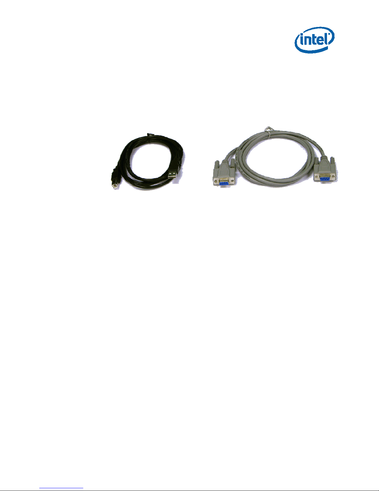
5. USB cable
6. Serial cable
Figure 5 shows the USB and Serial cables
Figure 5: USB and serial cable
7. Ten (10) Intel R1000 chips
8. Intel R1000 Collateral CD. The CD contains the following
o Intel R1000 software files:
Intel R1000 Firmware binary file
Intel R1000 host software binary files (Windows XP, Windows
CE and Linux versions. Please see Intel R1000 Software
Development Kit Getting Started Guide for full details)
Intel RFID Tracer Application binary files (Please see Intel
RFID Tracer Application User Guide for full details)
o Entire product documentation set
Intel R1000 Datasheet
Intel R1000 Evaluation Platform Application Note
Intel R1000 Firmware Datasheet
Intel R1000 Firmware Interface Specification
Intel R1000 Quick Start Guide
Intel RFID Transceiver Interface API Reference Manual
317118-001 / Quick Start Guide 9
Intel RFID Reader SDK Getting Started Guide
Intel R1000 Firmware Release Notes
Intel R1000 Firmware Upgrade Application Note
Page 10

Intel R1000 Quick Start
Intel RFID Tracer Demonstration Application
o Intel R1000 Evaluation Platform design collateral:
Base board & PA schematic
Base board and PA Gerber’s
Base board & PA BOM
2. Hard copy of this Quick Start Guide
Note: In order to use the Intel R1000 Evaluation Platform the users must supply the
following components:
1. A Host platform. For the remainder of this document the host platform is
assumed to be an IA-32 (aka. Pentium) based PC running Windows XP (SP1 or
later). However other host platforms are possible, please see Intel R1000
Software Development Kit Getting Started Guide for full details.
2. RFID ready antenna cables.
3. RFID ready antennas.
4. One or more 18000-6C Tags.
2.3 Reading Tags with the Intel R1000 Development
Platform
Note: The Intel R1000 Development Platform will always initialize in FCC mode, irrespective
of whether the platform hardware is targeted for FCC or ETSI compliant regions. Please
consult with your regulatory advisor to ensure you have the correct licences in place to
broadcast in the FCC or ETSI spectrum. In order to configure Intel R1000 Development
Platform to ETSI mode please consult Intel RFID Tracer User Guide.
Note: All computer boards are sensitive to electrostatic discharge. Handle all static-sensitive
boards and components at a static-safe work area, and observe anti-static precautions at all
times.
Note: The Intel R1000 Development Platform is shipped with the Intel R1000 Firmware in
persistent storage on the platform. No loading of the firmware is required in order to get the
platform to read tags.
Note: The Intel R1000 Development Platform default register setting values allow tags to be
read out of the box.
Note: Do not apply power to the system until the TX antenna ports have been terminated
either by an antenna or a termination connector.
10
317118-001 / Quick Start Guide
Page 11

Intel R1000 Quick Start
This section provides the steps to follow to get the Intel Evaluation Platform up and
reading tags. The Intel R1000 evaluation platform and software are very versatile, for
a full understanding of their capabilities you should consult the appropriate deep dive
document.
1. Install the following components from the Intel R1000 Collateral CD on the host
PC.
a. Intel RFID Tracer application. See Intel® RFID Tracer Application User
b. Intel R1000 USB Bus Driver for Windows XP.. See Intel® R1000 SDK
2. Connect the components as depicted in the Figure 5
Guide for details of how to install and launch this application.
Getting Started Guide for details of how to install the driver.
Figure 5: Component connections (using USB)
Note: The default ports
are TX1/RX3
Note: Ensure that the tag is stationary, positioned directly in front of the antenna at a
distance of about 1 meter. The goal is to verify correct setup rather than to exercise the Intel
R1000 read range or rate.
3. The Intel R1000 development platform is by default configured for a bistatic
antenna configuration (ie. a separate antenna is required for the Rx and Tx paths).
Please refer to the Intel R1000 Development Platform Application Note for
317118-001 / Quick Start Guide 11
and RX3
Page 12

Intel R1000 Quick Start
information on how to configure it to a monostatic configuration (ie. single Rx/Tx
antenna).
4. Apply power to the Intel R1000 Development Platform. At this point the Windows
XP will detect the platform and display the “Found New Hardware Wizard”.
a. The first screen asks if Windows “Can connect to Windows Update
to search for the software”, select “No, not this time” and then click
the “NEXT” button.
b. On the next wizard screen, select the “Install from a list of specific
location” option, then click the NEXT button.
c. On the next wizard screen:
i. Select the “Search for the best driver in these locations”
radio button.
ii. Uncheck the “Search removable media” check box
Check the “include this location in the search” box - and then
use the browse button to select the path where the USB driver
files usbharve.sys and usbharve.inf are located.
d. A dialog will popup indicating that the driver has not passed
“Windows Logo Testing”, click the “CONTINUE ANYWAY” button.
Note: If you are prompted again for a .sys file on an “installation
disk”, just use the browse button and point the dialog to the driver
file location again.
e. When the last screen appears, click the “Finish” button to dismiss
the New Hardware Wizard
5. Launch the RFID Tracer Application by selecting > Start > Programs > Intel RFID
SDK > Intel RFID Tracer
6. Execute an inventory command from the Intel RFID Tracer application and verify
that the tag data for the tag in the field of view of the antenna is returned to the
Tracer main window. See Intel® RFID Tracer Application User Guide for details on
how to operate the Intel RFID Tracer application.
12
317118-001 / Quick Start Guide
Page 13

Intel R1000 Quick Start
Figure 6: Example of three tags being captured by Intel RFID Tracer
2.4 Changing the Host Interface from USB to UART
The Intel R1000 Development Platform can be operated over USB or UART.
The development platform requires the USB cable to be plugged in to the PC
in order to power up even if using the serial port. This is because the platform
was designed for USB operation. When designing a system around the R1000 the USB
port can be omitted.
There are two ways to enable the UART interface.
Option 1: Using the debug port
Edit the file RFIDcomm.cfg. Change the number “1” to the actual COM port you would
like to use. Then copy this file into the directory from which the Tracer application will
run. To locate the Tracer application executable use Explorer to view the directory:
C:\Documents and Settings\[ USER ]\Local Settings\Apps\2.0\
Where [ USER ] is the name of the user active when the Tracer application was
installed on the system.
Once you have entered the indicated directory you should see one ( and possibly
more) directories with names consisting of what appear to be random character
317118-001 / Quick Start Guide 13
Page 14

Intel R1000 Quick Start
sequences. This name will change from machine to machine and from user to user
when ever Tracer is installed. If you enter that directory, you will notice it contains
one or more directories, again consisting of random character sequences.
At this point, you must look thru each of the ‘child’ directories and look for the RFID
Tracer.exe program and RFID Library dll files. The library file names of interest are
rfid.dll, rfidtx.dll and cpl.dll. The directory that contains all four of these files is the
directory where you should place the RFIDcomm.cfg file.
Connect the serial cable to the debug port and to your PC. Open a terminal program
such as HyperTerminal. Open a session with the settings 8N1 115kbps. Make sure the
USB cable is plugged into the PC and the development platform and the serial cable is
connected to the debug port of the development platform. Power up the development
platform.
In the HyperTerminal window, press the space bar before board boots to start the
debug shell.
Enter the following commands to switch between USB/UART
FOR SERIAL
->write_oemcfg
Valid OEM address are from 0x00 to 0xA2
Enter OEM config word ADDRESS
32 hex format NNNNNNNN, q to abort->000000A0
Enter OEM config word DATA
32 hex format NNNNNNNN, q to abort->00000001
write succeeded
FOR USB
->write_oemcfg
Valid OEM address are from 0x00 to 0xA2
Enter OEM config word ADDRESS
32 hex format NNNNNNNN, q to abort->000000A0
Enter OEM config word DATA
32 hex format NNNNNNNN, q to abort->00000000
write succeeded
Reboot the system then start Tracer. If you Tracer was already open, then you must
close and restart the application.
Option 2
Use the code example in the “R1000 Firmware Datasheet” Appendix D.
2.5 Next Steps
Once the basic operation of the Intel R1000 Development Platform has been verified,
we advise that you become familiar with the capabilities of the Intel R1000 and related
14
317118-001 / Quick Start Guide
Page 15

Intel R1000 Quick Start
related hardware and software components. Please refer to the table below for a quick
reference on how the documents relate to the Intel components.
Intel R1000 Intel R1000 Datasheet
Intel R1000 Firmware
Component Document
Intel R1000 Firmware Datasheet
Intel R1000 Firmware Interface Specification
Intel R1000 SDK Getting Started Guide
Intel R1000 Host Software
Intel R1000 Tracer
Application
Intel R1000 Development
Platform
Intel RFID Transceiver Interface Reference Manual
Intel R1000 Firmware Interface Specification
Intel RFID Tracer Application User Guide
Intel R1000 SDK Getting Started User Guide
Intel R1000 Development Platform Application Note
Base board and PA board Schematics, Gerbers and BOM
317118-001 / Quick Start Guide 15
 Loading...