

Page 1

Intel® IP Network Server
Intel® NSW1U (1Ux20”D)
Configuration Guide
System / Spares / Accessories List
Rev 1.2
A reference guide to assist customers and the field in ordering these
servers, accessories and spares
~Subject to Change Without Notice~
NSW1U
Page 2

May 2007
INFORMATION IN THIS DOCUMENT IS PROVIDED IN CONNECTION WITH INTEL®
PRODUCTS. NO LICENSE, EXPRESS OR IMPLIED, BY ESTOPPEL OR OTHERWISE, TO
ANY INTELLECTUAL PROPERTY RIGHTS IS GRANTED BY THIS DOCUMENT. EXCEPT
AS PROVIDED IN INTEL'S TERMS AND CONDITIONS OF SALE FOR SUCH PRODUCTS,
INTEL ASSUMES NO LIABILITY WHATSOEVER, AND INTEL DISCLAIMS ANY EXPRESS
OR IMPLIED WARRANTY, RELATING TO SALE AND/OR USE OF INTEL PRODUCTS
INCLUDING LIABILITY OR WARRANTIES RELATING TO FITNESS FOR A PARTICULAR
PURPOSE, MERCHANTABILITY, OR INFRINGEMENT OF ANY PATENT, COPYRIGHT
OR OTHER INTELLECTUAL PROPERTY RIGHT. Intel products are not intended for
use in medical, life saving, life sustaining applications.
Intel may make changes to specifications and product descriptions at any time,
without notice.
Intel server boards, server chassis, and processors may contain design defects
or errors known as errata, which may cause the product to deviate from
published specifications. Current characterized errata are available on request.
Intel, Intel Xeon, Pentium, and the Intel logo are trademarks or registered
trademarks of Intel Corporation or its subsidiaries in the United States and
other countries.
*Other names and brands may be claimed as the property of others.
Copyright © 2007, Intel Corporation
Page 3

Document Table of Contents
I. CHANGE HISTORY 6
II. INTRODUCTION 7
III. PRODUCTION SKUS 9
IV. PRODUCTION SPARES/ACCESSORY LIST 17
V. ADDING BYPASS ETHERNET PORTS 21
VI. DOCUMENTATION 23
APPENDIX A. BASE MODEL 0 SYSTEMS CONFIGURATION 24
APPENDIX B. RACK MOUNTING OPTIONS FOR 1U AND 2U INTEL®
COMMUNICATIONS RACK MOUNT SERVERS 27
5/18/2007 v1.2 3 of 21
Page 4

I. Change History
Revision Date Comments
1.0 11/10/2006 Original version.
1.1 3/19/2007 Updated at SRA. Added Front NIC Bypass SKU.
1.2 5/17/2007 Updated Spares list; new Rack Mount appendix; misc.
updates
5/18/2007 v1.2 4 of 21
Page 5

II. Introduction
The Intel® IP Network Server NSW1U system is the first 1U rack mount server to
join the Intel® IP Network Server family, characterized by having long product
life and a 20” depth chassis. The NSW1U uses the Dual-Core Intel® Xeon®
Processor 5100 Series with 4M cache, and supports a number of CPU speeds.
Intel® IP Network Servers are suited to a host of applications in the network
security and industrial environment. The server is targeted to applications
requiring rugged systems including Intrusion Detection, Intrusion Protection,
Firewall, VPN, SSL VPN, and Application Secure Gateways. It can also support
manufacturing, industrial, utility and military applications where a rugged,
highly reliable server is required for harsh environments such as dust, high
altitude, fire hazard, earthquake propensity, and high ambient temperatures.
The NSW1U product has several phases before being released for general
customer availability (SRA – Ship Release Authorization). These phases include a
Beta, Silver, and Production phase. This document details the options available
on the Production systems.
5/18/2007 v1.2 5 of 21
Page 6

III. Production SKUs
Intel IP Network Servers:
Production NSW1U Server – Rear NIC (AC Supply) - Product Code NSWA0201W
Production NSW1U Server – Rear NIC (DC Supply) - Product Code NSWD0201W
Production NSW1U Server – Front NIC (AC Supply) - Product Code NSWA0301W
Production NSW1U Server – Front NIC with Bypass (AC Supply) - Product Code
NSWA0401W
All listed Production SKUs are model 0 SKUs (no CPU, heatsink, memory, hard
drive or plug-in adapters are provided). Those components must be ordered
separately as Accessories from Intel or from third party vendors listed in the
Tested Hardware and Operating System List (THOL). See Appendix A –
Production SKU Configuration for a list of components included in each
Production model 0 SKU.
NSW1U is designed for the Dual-Core Intel® Xeon® Processor 5100 Series with 4M
L2 cache, and 1066MHz/1333MHz FSB.
Check the following site for more information on the NSW1U:
http://www.intel.com/design/telecom/products/cbp/ipserver/9979/overview.h
tm
Intel® Network Server NSW1U support web site:
http://support.intel.com/support/telecom/computeboards/nsw1u/index.htm
Please note the following:
Please refer to the Intel® IP Network Server NSW1U product
documentation.
AC Power cords are not provided with the base system. Customers
must procure the power cords separately (for AC systems, order the NA
– North American - power cord as indicated).
Ensure customers have the appropriate technical support and contact
before placing the first order.
The NSW1U base configuration comes with a riser to support 1 PCI-
Express slot. An optional replacement riser may be ordered to support
a 1 slot PCI-X.
5/18/2007 v1.2 6 of 21
Page 7
Special instructions for Ordering of Processors:
The NSW1U supports a range of processor speeds from 1.6 GHz to 3.0 GHz.
Ordering details for the CPU for use in NSW1U are listed below, and includes
both Tray (for OEMs) and Boxed (Retail channel) processors.
Dual-Core Intel® Xeon® Processors Supported by NSW1U:
Processor
Number
5160 3.00 GHz 1333 MHz 80W BX805565160A HH80556KJ0804M
5150 2.66 GHz 1333 MHz 65W BX805565150A HH80556KJ0674M
5140 2.33 GHz 1333 MHz 65W BX805565140A HH80556KJ0534M
5130 2.00 GHz 1333 MHz 65W BX805565130A HH80556KJ0414M
5120 1.86 GHz 1066 MHz 65W BX805565120A HH80556KH0364M
5110 1.6 GHz 1066 MHz 65W BX805565110A HH80556KH0254M
LV 5148 2.33 GHz 1333 MHz 40W BX805565148A HH80556JJ0534M
LV 5128 1.86 GHz 1066 MHz 40W N/A HH80556JH0364M
Notes:
Although all of the above processors are tested and supported, Intel
recommends the use of the following processors from Intel’s Infrastructure
Processor Division (IPD) for long availability and support.
The boxed CPUs listed above include a Active/Passive Heatsink Kit.
Simply remove the fan from the Kit, and install into the system as shown
in the product documentation.
For Tray CPUs, you will need to procure a Heatsink Kit (TMWHSNK01W)
and thermal grease for each processor.
Note that CPU product codes can change, and that the above is a snapshot
current as of 5/17/2007. Please consult with your Intel representative for SSpec
or MM# which may be needed for ordering the CPU. Any differences in
functionality is reported in Monthly Specification updates available on
http://developer.intel.com
Speed FSB TDP Boxed Processor
Product Code
o 5140 (2.33 GHz, 1333MHz FSB, 65W)
o 5130 (2.00 GHz, 1333MHz FSB, 65W)
o LV 5148 (2.33 GHz, 1333MHz FSB, 40W)
o LV 5128 (1.86 GHz, 1066MHz FSB, 40W)
.
Tray Processor
Product Code
5/18/2007 v1.2 7 of 21
Page 8

The Production SKUs that can be ordered (see Appendix A for content of each
SKU) are listed below.
PID Order Code Description MM# Minimum
Order
Size
NSWA0201W Intel® IP Network Server NSW1U, 1U,
885432 1
Rear NIC, Base Model 0*.
Includes 450W AC Power Supply.
NSWD0201W Intel® IP Network Server NSW1U, 1U,
Rear NIC, Base
Model 0*.
885433 1
Includes 450W DC Power Supply.
NSWA0301W Intel® IP Network Server NSW1U, 1U,
885501 1
Front NIC, Base Model 0*.
Includes 450W AC Power Supply.
NSWA0401W Intel® IP Network Server NSW1U, 1U,
888296 1
Front NIC with Bypass, Base Model 0*.
Includes 450W AC Power Supply.
*Note: See definition of “base model 0” at beginning of section III.
Power Cords are not included. For AC Power cords, order the power cord below.
This power cable is RoHS-compliant.
PID MM# Comments
PWRCABLEUS 816324
This AC power cable may be ordered by North America
(NA) customers. International customers should
procure their specific power cords directly.
5/18/2007 v1.2 8 of 21
Page 9

IV. Production Spares/Accessory List
Below are the Spares parts and Accessories that may be ordered with the NSW1U
system. Any of these parts may be ordered as spares for part replacement
purposes or as additional customer inventory. Some of the parts below are not
included in the NSW1U system base model and may be ordered as accessories for
purposes of upgrading the base model to include additional features.
Many of these parts are common to the Intel® Carrier Grade Server TIGW1U
product. For a listing of additional compatible accessories, such as Optical
Devices for use with the CD-ROM carrier, please refer to the Tested Hardware
and Operating System List (THOL).
PID Order Code
TMWACPSU01W
TMWDCPSU01W
TMWHSNK01W
TMWCDRMC01W
TMWSYSCON01W
AXXRMM2
AXXRMM2BULK
NSWDBCBL01W
TMWPCIXRSR01W
TMWPCIERSR01W
Description
TIGW1U AC Power Supply
TIGW1U DC Power Supply
TIGW1U CPU Heatsink
TIGW1U CD-ROM Carrier; i/f board
(no drive)
TIGW1U Syscon Board
Intel® Remote Management Module 2
(RMM2) - Single Pack
Intel® Remote Management Module 2
(RMM2) - Bulk Pack (10)
NSW1U NIC Cable
TIGW1U PCI-X Riser
TIGW1U PCI-Express Riser
Contents
AC power supply
DC power
supply, input
power connector
Heatsink
Carrier, PBA,
screws, pwr
cable, signal
cable
Board, cable,
screws (mini-SD
flash memory
not included)
RMM2 with GCM
(single-pack)
RMM2 with GCM
(10-pack)
Cable, PCI
Support Bracket,
escutcheon,
screws
Riser, screws
Riser, screws
Included
in Base
Model
(Y/N)
Y
one in AC
SKU
Y
one in DC
SKU
N
N
N
N
N
N
N
Y
MM# Minimum
Order
Size
886492
886537
887151
886842
886484
888501
888498
886591
886491
886490
1
1
12
(order in
multiples of 12)
1
1
1
1
(specify ‘1’ for
each 10-pack)
5
(order in
multiples of 5)
1
1
5/18/2007 v1.2 9 of 21
Page 10

Production Spares/Accessories List (continued)
PID Order Code
NSWFBZL01W
NSWFBZL02W
NSWCBLBRK01W
NSIESCFBR100
NSWCDFILL01W
NSWSATAHDD01W
NSWFANSET01W
TMWCBL01W
TMWPDB01W
NSWEFPR01W
NSWEFPF01W
NSWBSBRDR01W
NSWBSBRDF01W
NSWBYPSBRD01W
Description
NSW1U Bezel - Rear NIC
NSW1U Bezel – Front NIC
NSW1U Cable Management Bracket
NSI2U Fiber Escutcheon packaged in
cartons of 48
NSW1U CD-ROM filler
NSW1U SATA HDD Carriers
NSW1U Fanset
TIGW1U Cables, CD-ROM power,
spare
TIGW1U Power Distribution Board
NSW1U Ethernet Front Panel I/O
Board - Rear NIC, Litepipe
NSW1U Ethernet Front Panel I/O
Board - Front NIC, Litepipe
NSW1U Baseboard - Rear NIC
NSW1U Baseboard - Front NIC
NSW1U Ethernet Front Panel - Front
NIC with Bypass
Contents
Bezel
Bezel
Bracket for
chassis face
Escutcheons
(48-pack)
CD filler
2 carriers
Fans, bracket,
air ducts
System cables—
Flex, CD-ROM
power, CD-ROM
signal, SATA
Signal, Front
Panel Panel,
Battery
Board
Board, litepipe
Board, litepipe
Board
Board
Board
Included
in Base
Model
(Y/N)
Y
one in Rear
NIC SKU
one in Front
NIC SKU
one in Rear
NIC SKU
one in Front
NIC SKU
one in Rear
NIC SKU
one in Front
NIC SKU
one in Front
NIC SKU
Y
N
N
N
Y
Y
Y
Y
Y
Y
Y
Y
Y
MM# Minimum
Order
Size
886614
886615
886590
880102
886841
886589
886544
886613
886538
886540
886543
886849
886853
886812
1
1
5
(order in
multiples of 5)
48
(order in
multiples of 48)
1
1
1
1
1
1
1
1
1
1
5/18/2007 v1.2 10 of 21
Page 11

V. Adding Bypass Ethernet ports
The NSW1U comes standard with 4 Gb Ethernet ports either in the front or rear
of the chassis. By adding the Intel® Pro/1000 PT or PF Quad Port Bypass Server
Adapter, four additional ports of Gbit ethernet (either Copper or Fiber) may be
added. These NIC adapters may be purchased separately via normal distribution
channels.
The Quad Copper NIF Bypass adapters require purchase of the NSWDBCBL01W
kit, which includes 5 of the NIF cables designed for the NSW1U system, as well as
the Escutcheons and associated screws to complete the installation of the Bypass
adapter in the system.
The Quad Fiber NIF Bypass adapters require purchase of the NSIESCFBR100
escutcheon accessory.
Intel LAD NIC Order Codes:
PID order code Description MM# Minimum
Order Size
EXPI9014PTBLK
EXPI9024PTBLK
EXPI9014PFBLK
EXPI9024PFBLK
Quad Copper Gb Bypass NIC,
5 PACK
Quad Copper Gb Bypass NIC
in Front, 5 PACK
Quad Fiber Gb Bypass NIC, 5
PACK
Quad Fiber Gb Bypass NIC in
Front, 5 PACK
876697 5
876699 5
876696 5
876694 5
Note: For a list of other tested Network Interface Cards (NICs) refer to the
Tested Hardware and Operating System List (THOL).
5/18/2007 v1.2 11 of 21
Page 12

VI. Documentation
More Product Details:
Check the following web site for more information on the TIGW1U:
http://www.intel.com/design/telecom/products/cbp/ipserver/9979/overview.h
tm
Support.Intel.Com Users:
Product information including specifications, compatibility, user’s guides,
drivers, firmware, and software associated with the Intel® Network Server
NSW1U is available from Intel Customer Support.
Intel® Network Server NSW1U support web site:
http://support.intel.com/support/telecom/computeboards/nsw1u/index.htm
If you can not access the documents using the links provided, please contact your
FAE/FSE for assistance.
5/18/2007 v1.2 12 of 21
Page 13

Appendix A. Base Model 0 Systems Configuration
All Production SKUs are base model 0 SKUs (no CPU, heatsink, memory, hard
drive or plug-in adapters are provided). Those components must be ordered
separately as Accessories from Intel or from third party vendors listed in the
Tested Hardware and Operating System List (THOL). The below table lists how
many of each component is included in the Production model 0 SKU.
NSW1U Production SKU Configuration
Component Description
Chassis (bezel, sheet metal, top cover, PCI
carrier)
S5000PHB Baseboard
(Dual-Core Intel® Xeon® Processor 5100
Series with 4M L2 cache, and 1066MHz and
1333MHz FSB) – CPUs not included
FH-FL Bracket with PCI-Express Riser 1 1
AC power supply (450W) 1 DC power supply (450W) - 1
Power Supply Filler Panel 1 1
SATA HDD Carrier
Server Deployment Toolkit (CD) 1 1
Quick Start Guide 1 1
Power cable1 Purchase separately Purchase separately
CD-ROM Carrier
PCI-X Riser2 Optional Accessory Optional Accessory
Syscon Board2 Optional Accessory Optional Accessory
Intel® Remove Management Module 22 Optional Accessory Optional Accessory
NIC Cable2 Optional Accessory Optional Accessory
Cable Management Bracket2 Optional Accessory Optional Accessory
Bypass Ethernet Ports3 Optional Accessory Optional Accessory
Rack Mount Kits4 Optional Accessory Optional Accessory
Some items above available as optional accessories as noted:
1
Refer to AC power cord accessory in section III
2
Refer to “Production Spares/Accessory List” in section IV
3
Refer to “Adding Bypass Ports” in section V
4
Refer to “Rack Mounts” in Appendix B
Note: For these SKUs to be functional, one or more of the following is
required: Power cord, CPU, Memory, Hard Drive, Operating System, Heatsinks
Configuration
AC SKU
1 1
1 1
2 2
Optional Accessory Optional Accessory
Configuration
DC SKU
5/18/2007 v1.2 13 of 21
Page 14

Appendix B. Rack Mounting Options for 1U and 2U Intel®
Communications Rack Mount Servers
Rack mounting kits for 2-post or 4-post, 19-inch or 23-inch racks are offered for
this product. Please refer to the tables below for the correct options to suit your
needs.
All rack mount kits listed are suitable for 1U and 2U Intel® Communications Rack
Mount Servers. Installation instructions are included in each kit.
2-post Rack Mounting Kit Options
Rack width Post depth Rack fastener hole spacing
Applicable kits:
19 inch 23 inch
3 inch 5 inch EIA-Wide EIA-Universal ETSI
TMLCMOUNT21
TMLPMOUNT41
TMLPMOUNT51
TMLPMOUNT52
4-post Rack Mounting Kit Options
Rack width
Applicable kits:
19 inch 23 inch
TMLPMOUNT41
TMLPMOUNT51
TMLPMOUNT52
TMLPSLIDE01†
†
The TMLPSLIDE01 kit contains server securing brackets. The rails and other
Front-post to
rear-post distance
Min
(inches)
20 24
20 24
20 24
22.5 28 or 34
Max
(inches)
††
options for mounting the server are available through other venders such as
Accuride (http://www.accuride.com/index2.php
††
34-inch span requires the optional Accuride "Long Bracket" kit.
).
Rack fastener
hole spacing
EIA-
Wide
Universal
EIA-
ETSI
5/18/2007 v1.2 14 of 21
Page 15

TMLCMOUNT21
The TMLCMOUNT21 kit mounts Intel® Communication Rack Mount Servers to a 2post, central office type, 19” wide rack. This kit consists of simple L-shaped
brackets; which fasten to the sides of the server and to the rack.
TMLCMOUNT21
5/18/2007 v1.2 15 of 21
Page 16

TMLPMOUNT41, TMLPMOUNT51 and TMLPMOUNT52
TMLPMOUNT41/51/52 series mounts Intel® Communication Rack Mount Servers
to 2-post or 4-post racks.
TMLPMOUNT41 and TMLPMOUNT51 are used for mounting servers on 19” wide
racks. These racks are considered standard EIA (universal hole spacing) racks.
TMLPMOUNT52 is used for mounting servers on 23” wide racks. These racks could
be standard EIA (universal or wide hole spacing) or ETSI (European) racks.
TMLPMOUNT41/51/52 series are designed with a slide-in rail-type system.
Although the mounts are designed as rails, they are not sliding rails. This means
the servers can be slid into the racks for installation purpose, but the rails are
not designed to support a mounted server during service.
TMLPMOUNT4x/5x feature comparison
spacing
4-post rack hole
2U-tall nut bar
Not
included
Included
Included
5
5
2-post chassis
securing screw
Side
access6
Front
access
Front
access
Slide pull-out
locking feature
TMLPMOUNT41 No1
TMLPMOUNT51 Yes
TMLPMOUNT52 Yes
Slide interface
Plastic
strips
Xylan
coating
Xylan
coating
material
2
EIA-Universal
EIA-Wide or EIA-
3
3
Universal4
EIA-Wide, EIA-
Universal or ETSI
Notes:
1. Extra care must be exercised with TMLPMOUNT41 to securely hold the
server with one's hands when sliding it out of the rack, else the server may
fall to the ground as its being removed.
2. Plastic strips on TMLPMOUNT41 have peeled off in some customer
installations. Consequence: The parts are usable, but the server may have
somewhat of a "scrape-in feel" rather than "slide in". Also, the rails will fit
sloppier, so the side-located chassis securing screws may be difficult to
align in 2-post installations. Replacement material is available from the
plastic strip manufacturer.
3. Xylan is a tough, low-friction coating similar to Teflon.
location
Interference
Interferance
rack
"HP Mulan
interference"
No
N/A
5/18/2007 v1.2 16 of 21
Page 17

4. EIA-Wide spacing doesn't have the interstitial hole that is present in EIAUniversal. TMLPMOUNT51 contains an adapter bracket to overcome this
EIA-Wide issue.
5. This component (2U Nut Bar) enables installation of a rail kit into a 1U
rack slot when there is already equipment installed both above and below
that open slot.
6. The sides of the server must be accessible when using TMLPMOUNT41 in 2-
post racks.
5/18/2007 v1.2 17 of 21
Page 18

The diagrams above summarize the components and “slide-in rail-type” system
of the TMLPMOUNT41. It can be adapted for a 2-post or 4-post installation.
5/18/2007 v1.2 18 of 21
Page 19
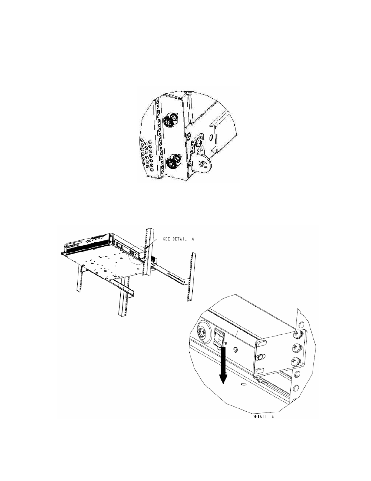
The main difference between the TMLPMOUNT41 and TMLPMOUNT51/52 series is
that the TMLPMOUNT41 series uses a screw to lock the server in place via the
Universal Mounting Bracket, whilst the TMLPMOUNT51/52 series has an
additional Slide Pull-Out Locking feature.
The Universal Front Mounting Bracket on the TMLPMOUNT41
The Slide Pull-Out Locking feature on the TMLPMOUNT51/52
5/18/2007 v1.2 19 of 21
Page 20

TMLPSLIDE01
The TMLPSLIDE01 is an accessory kit designed for use in conjunction with slide
rails to produce a rack mounted serviceable server. The TMLPSLIDE01 kit
contains two Universal Front Mounting Brackets
that secure the server to the
front of the rack. The sliding rails and optional mounting brackets required to
mount the server must be purchased through the channel. For example, the
Accuride 22-inch Model 305A-LR slide rails are designed to mount a server for
“in-rack service.” This example would also use an Accuride mounting bracket kit
and the TMLPSLIDE01.
Universal Front Mounting Bracket with securing tab
Note: Using slide rails may result in non-compliance with Seismic Zone 4
requirements of NEBS-3 certification.
Ordering Information
PID Non-RoHS MM# RoHS MM#
TMLCMOUNT21 862501 881904 10
TMLPMOUNT41 838890 881907 10
TMLPMOUNT51 851760 881934 1
TMLPMOUNT52 851745 881935 1
TMLPSLIDE01 845583 881915 10
Minimum Order
Quantity
5/18/2007 v1.2 20 of 21
Page 21

Customers should order RoHS items for shipments going to the European Union
(EU).
Although these mounts have been designed for industry standard racks, please
consult with your Intel Field Application or Sales Engineer before selecting racks
for these servers.
Compatible rack mounting kits may also be obtained from 3rd party suppliers.
5/18/2007 v1.2 21 of 21
 Loading...