

Page 1

Nios II Custom Instruction User Guide
Subscribe
Send Feedback
UG-20286 | 2020.04.27
Latest document on the web: PDF | HTML
Page 2

Contents
Contents
1. Nios II Custom Instruction Overview..............................................................................4
1.1. Custom Instruction Implementation......................................................................... 4
1.1.1. Custom Instruction Hardware Implementation............................................... 5
1.1.2. Custom Instruction Software Implementation................................................ 6
2. Custom Instruction Hardware Interface......................................................................... 7
2.1. Custom Instruction Types....................................................................................... 7
2.1.1. Combinational Custom Instructions.............................................................. 8
2.1.2. Multicycle Custom Instructions...................................................................10
2.1.3. Extended Custom Instructions................................................................... 11
2.1.4. Internal Register File Custom Instructions................................................... 13
2.1.5. External Interface Custom Instructions....................................................... 15
3. Custom Instruction Software Interface.........................................................................16
3.1. Custom Instruction Software Examples................................................................... 16
3.2. Built-in Functions and User-defined Macros..............................................................17
3.2.1. Built-in Functions with No Return Value.......................................................18
3.2.2. Built-in Functions that Return a Value of Type Int......................................... 18
3.2.3. Built-in Functions that Return a Value of Type Float...................................... 19
3.2.4. Built-in Functions that Return a Pointer Value...............................................19
3.3. Custom Instruction Assembly Language Interface.................................................... 20
3.3.1. Custom Instruction Assembly Language Syntax........................................... 20
3.3.2. Custom Instruction Assembly Language Examples........................................20
3.3.3. Custom Instruction Word Format................................................................21
4. Design Example: Cyclic Redundancy Check................................................................... 23
4.1. Building the CRC Example Hardware.......................................................................23
4.1.1. Setting up the Environment for the CRC Example Design...............................24
4.1.2. Opening the Component Editor.................................................................. 24
4.1.3. Specifying the Custom Instruction Component Type......................................25
4.1.4. Displaying the Custom Instruction Block Symbol.......................................... 26
4.1.5. Adding the CRC Custom Instruction HDL Files.............................................. 26
4.1.6. Configuring the Custom Instruction Parameter Type......................................28
4.1.7. Setting Up the CRC Custom Instruction Interfaces........................................ 29
4.1.8. Configuring the Custom Instruction Signal Type........................................... 31
4.1.9. Saving and Adding the CRC Custom Instruction........................................... 32
4.1.10. Generating and Compiling the CRC Example System................................... 33
4.2. Building the CRC Example Software........................................................................33
4.2.1. Running and Analyzing the CRC Example Software....................................... 34
4.2.2. Using the User-defined Custom Instruction Macro.........................................35
5. Introduction to Nios® II Floating Point Custom Instructions........................................ 37
5.1. Floating Point Background.....................................................................................39
5.2. IEEE 754 Format..................................................................................................39
5.2.1. Unit in the Last Place................................................................................39
5.2.2. Floating Point Value Encoding.................................................................... 40
5.3. Rounding Schemes...............................................................................................41
5.3.1. Nearest Rounding.................................................................................... 41
Nios II Custom Instruction User Guide
2
Send Feedback
Page 3

Contents
5.3.2. Truncation Rounding.................................................................................41
5.3.3. Faithful Rounding..................................................................................... 41
5.3.4. Rounding Examples..................................................................................42
5.4. Special Floating Point Cases.................................................................................. 42
6. Nios II Floating Point Hardware 2 Component.............................................................. 44
6.1. Overview of the Floating Point Hardware 2 Component..............................................44
6.2. Floating Point Hardware 2 IEEE 754 Compliance.......................................................46
6.3. IEEE 754 Exception Conditions with FPH2................................................................47
6.4. Floating Point Hardware 2 Operations..................................................................... 47
6.5. Building the FPH2 Example Hardware..................................................................... 49
6.6. Building the FPH2 Example Software...................................................................... 51
6.6.1. FPH2 and Nios II GCC...............................................................................52
6.6.2. Floating Point Hardware 2 Conversions........................................................52
6.6.3. Nios II FPH2 Software Options................................................................... 53
6.7. FPH2 Implementation of GCC Options.....................................................................55
6.7.1. -fno-math-errno...................................................................................... 55
6.7.2. -fsingle-precision-constant........................................................................ 55
6.7.3. -funsafe-math-optimizations......................................................................56
6.7.4. -ffinite-math-only.................................................................................... 56
6.7.5. -fno-trapping-math.................................................................................. 56
6.7.6. -frounding-math...................................................................................... 57
6.8. Nios II FPH2 and the Newlib Library........................................................................57
6.9. C Macros for round(), fmins(), and fmaxs()............................................................. 58
7. Nios II Floating Point Hardware (FPH1) Component.....................................................59
7.1. Creating the FPH1 Example Hardware ...................................................................59
7.2. Adding FPH1 to the Design and Configuring the Device............................................. 60
7.3. Building the FPH1 Example Software...................................................................... 61
7.3.1. Creating the FPH1 Software Project............................................................ 61
7.3.2. Running and Analyzing the FPH1 Example Software......................................61
7.3.3. Software Implementation for FPH1............................................................. 63
7.4. Nios II FPH1 and the Newlib Library........................................................................63
7.5. Assessing Your Floating Point Optimization Needs.....................................................63
7.6. Hardware Divide Considerations with FPH1..............................................................64
8. Document Revision History for Nios II Custom Instruction User Guide......................... 66
Send Feedback
Nios II Custom Instruction User Guide
3
Page 4
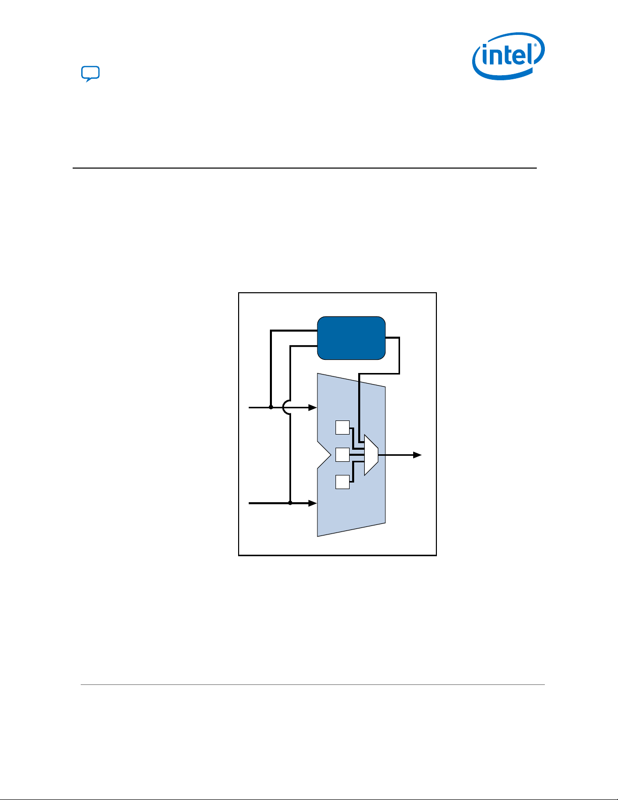
Nios II Embedded Processor
+
–
&
<<
>>
Result
A
Nios II
ALU
B
Custom
Logic
UG-20286 | 2020.04.27
Send Feedback
1. Nios II Custom Instruction Overview
Custom instructions give you the ability to tailor the Nios II processor to meet the
needs of a particular application. You can accelerate time critical software algorithms
by converting them to custom hardware logic blocks. Because it is easy to alter the
design of the FPGA-based Nios II processor, custom instructions provide an easy way
to experiment with hardware-software tradeoffs at any point in the design process.
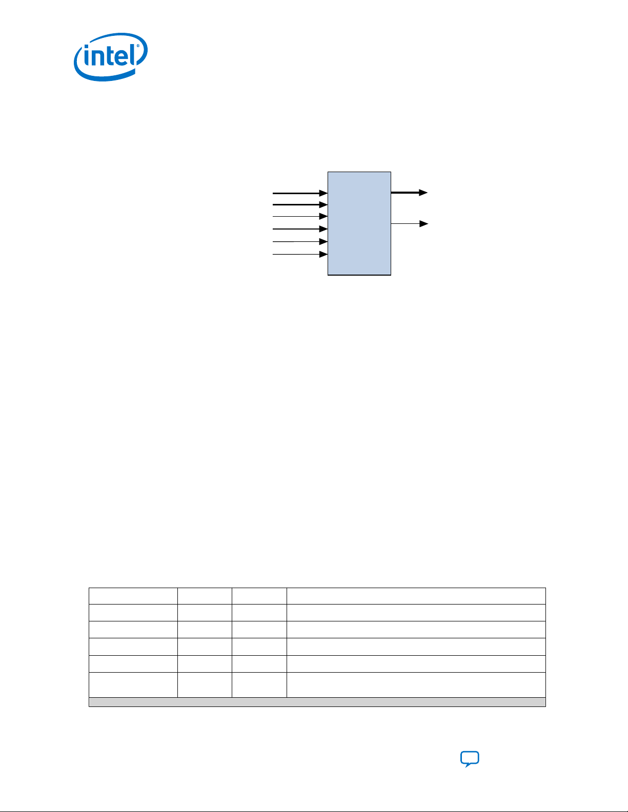
The custom instruction logic connects directly to the Nios II arithmetic logic unit (ALU)
as shown in the following figure.
Figure 1. Custom Instruction Logic Connects to the Nios II ALU
Related Information
• Custom Instruction Software Interface on page 16
• Building the CRC Example Hardware on page 23
1.1. Custom Instruction Implementation
Nios II custom instructions are custom logic blocks adjacent to the arithmetic logic
Intel Corporation. All rights reserved. Agilex, Altera, Arria, Cyclone, Enpirion, Intel, the Intel logo, MAX, Nios,
Quartus and Stratix words and logos are trademarks of Intel Corporation or its subsidiaries in the U.S. and/or
other countries. Intel warrants performance of its FPGA and semiconductor products to current specifications in
accordance with Intel's standard warranty, but reserves the right to make changes to any products and services
at any time without notice. Intel assumes no responsibility or liability arising out of the application or use of any
information, product, or service described herein except as expressly agreed to in writing by Intel. Intel
customers are advised to obtain the latest version of device specifications before relying on any published
information and before placing orders for products or services.
*Other names and brands may be claimed as the property of others.
unit (ALU) in the processor’s datapath.
ISO
9001:2015
Registered
Page 5
Combinatorial
Conduit interface to external
memory, FIFO, or other logic
Multi-cycle
result [31..0]
Extended
Internal
Register File
done
dataa[31..0]
datab[31..0]
clk
clk_en
reset
start
n[7..0]
a[4..0]
readra
b[4..0]
readrb
c[4..0]
writerc
Combinational
Custom
Logic
1. Nios II Custom Instruction Overview
UG-20286 | 2020.04.27
When custom instructions are implemented in a Nios II system, each custom
operation is assigned a unique selector index. The selector index allows software to
specify the desired operation from among up to 256 custom operations. The selector
index is determined at the time the hardware is instantiated with the Platform
Designer or Platform Designer (Standard) software. Platform Designer exports the
selection index value to system.h for use by the Nios II software build tools.
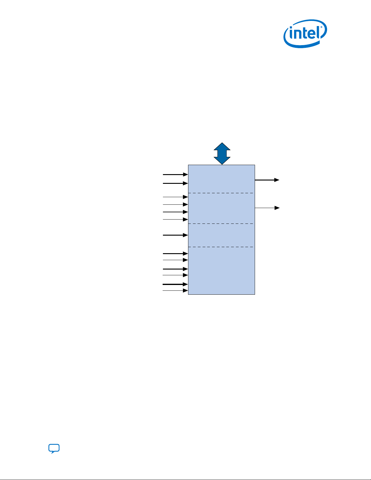
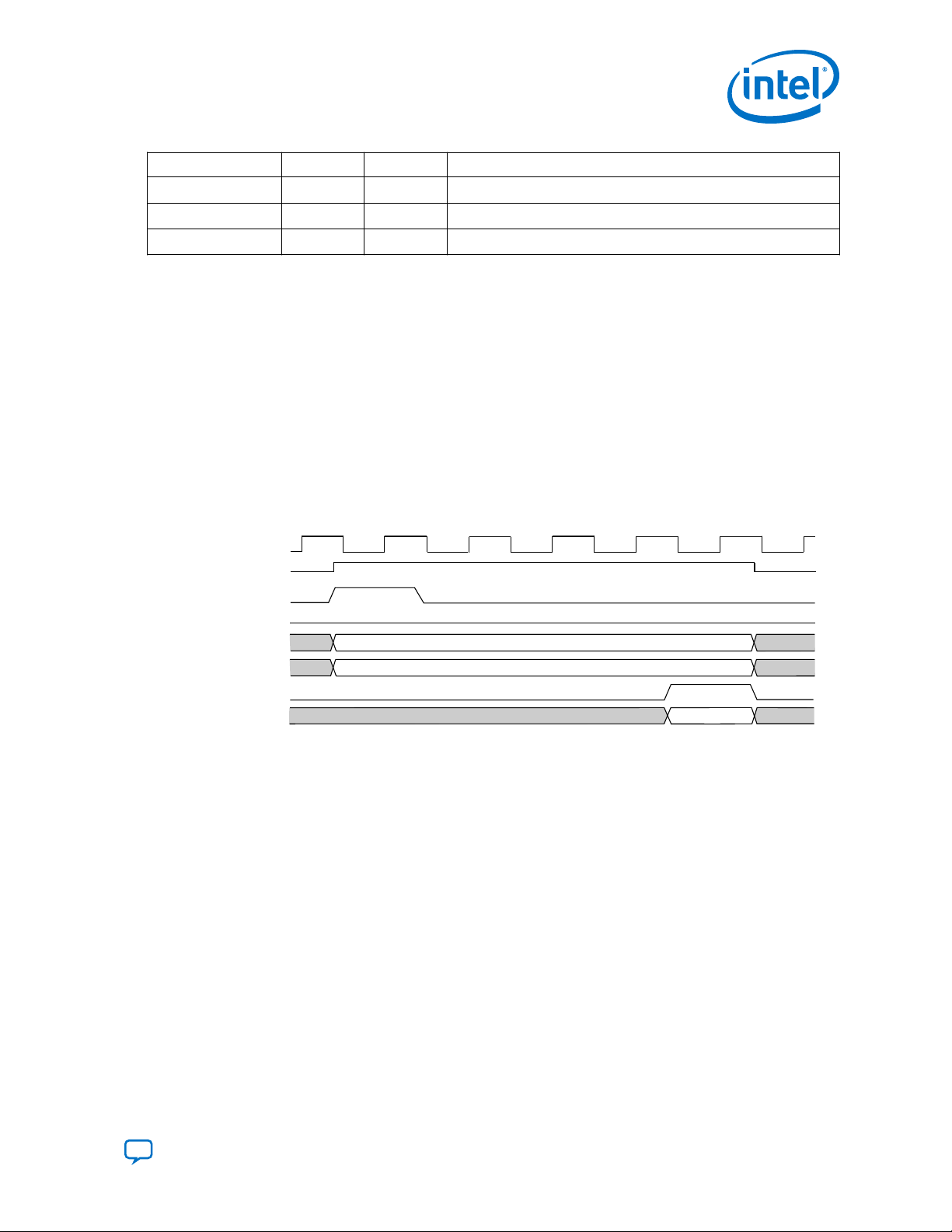
1.1.1. Custom Instruction Hardware Implementation
Figure 2. Hardware Block Diagram of a Nios II Custom Instruction
A Nios II custom instruction logic block interfaces with the Nios II processor through
three ports: dataa, datab, and result.
The custom instruction logic provides a result based on the inputs provided by the
Nios II processor. The Nios II custom instruction logic receives input on its dataa
port, or on its dataa and datab ports, and drives the result to its result port.
The Nios II processor supports several types of custom instructions. The figure above
shows all the ports required to accommodate all custom instruction types. Any
particular custom instruction implementation requires only the ports specific to its
custom instruction type.
The figure above also shows a conduit interface to external logic. The interface to
external logic allows you to include a custom interface to system resources outside of
the Nios II processor datapath.
Send Feedback
Nios II Custom Instruction User Guide
5
Page 6

1. Nios II Custom Instruction Overview
1.1.2. Custom Instruction Software Implementation
The Nios II custom instruction software interface is simple and abstracts the details of
the custom instruction from the software developer.
For each custom instruction, the Nios II Embedded Design Suite (EDS) generates a
macro in the system header file, system.h. You can use the macro directly in your C
or C++ application code, and you do not need to program assembly code to access
custom instructions. Software can also invoke custom instructions in Nios II processor
assembly language.
Related Information
Custom Instruction Software Interface on page 16
UG-20286 | 2020.04.27
Nios II Custom Instruction User Guide
6
Send Feedback
Page 7
UG-20286 | 2020.04.27
Send Feedback
2. Custom Instruction Hardware Interface
2.1. Custom Instruction Types
Different types of custom instructions are available to meet the requirements of your
application. The type you choose determines the hardware interface for your custom
instruction.
Table 1. Custom Instruction Types, Applications, and Hardware Ports
Instruction Type Application Hardware Ports
Combinational Single clock cycle custom logic blocks. •
Multicycle Multi-clock cycle custom logic blocks of fixed or
variable durations.
dataa[31:0]
•
datab[31:0]
•
result[31:0]
•
dataa[31:0]
•
datab[31:0]
•
result[31:0]
•
clk
•
clk_en
•
start
•
reset
•
done
(1)
continued...
(1)
The clk_en input signal must be connected to the clk_en signals of all the registers in the
custom instruction, in case the Nios II processor needs to stall the custom instruction during
execution.
Intel Corporation. All rights reserved. Agilex, Altera, Arria, Cyclone, Enpirion, Intel, the Intel logo, MAX, Nios,
Quartus and Stratix words and logos are trademarks of Intel Corporation or its subsidiaries in the U.S. and/or
other countries. Intel warrants performance of its FPGA and semiconductor products to current specifications in
accordance with Intel's standard warranty, but reserves the right to make changes to any products and services
at any time without notice. Intel assumes no responsibility or liability arising out of the application or use of any
information, product, or service described herein except as expressly agreed to in writing by Intel. Intel
customers are advised to obtain the latest version of device specifications before relying on any published
information and before placing orders for products or services.
*Other names and brands may be claimed as the property of others.
ISO
9001:2015
Registered
Page 8

2. Custom Instruction Hardware Interface
UG-20286 | 2020.04.27
Instruction Type Application Hardware Ports
Extended Custom logic blocks that are capable of
Internal register file
External interface Custom logic blocks that interface to logic
performing multiple operations
Custom logic blocks that access internal register
files for input or output or both.
outside of the Nios II processor’s datapath
•
dataa[31:0]
•
datab[31:0]
•
result[31:0]
•
clk
•
clk_en
•
start
•
reset
•
done
•
n[7:0]
•
dataa[31:0]
•
datab[31:0]
•
result[31:0]
•
clk
•
clk_en
•
start
•
reset
•
done
•
n[7:0]
•
a[4:0]
•
readra
•
b[4:0]
•
readrb
•
c[4:0]
•
writerc
Standard custom instruction ports, plus userdefined interface to external logic.
(1)
(1)
2.1.1. Combinational Custom Instructions
A combinational custom instruction is a logic block that completes its logic function in
a single clock cycle.
A combinational custom instruction must not have side effects. In particular, a
combinational custom instruction cannot have an external interface. This restriction
exists because the Nios II processor issues combinational custom instructions
speculatively, to optimize execution. It issues the instruction before knowing whether
it is necessary, and ignores the result if it is not required.
A basic combinational custom instruction block, with the required ports shown in
"Custom Instruction Types", implements a single custom operation. This operation has
a selection index determined when the instruction is instantiated in the system using
Platform Designer.
You can further optimize combinational custom instructions by implementing the
extended custom instruction. Refer to “Extended Custom Instructions”.
Related Information
• Extended Custom Instructions on page 11
• Custom Instruction Types on page 7
List of standard custom instruction hardware ports, to be used as signal types
Nios II Custom Instruction User Guide
8
Send Feedback
Page 9
dataa[31..0]
datab[31..0]
Combinational result[31..0]
clk
T0
T1 T3T2 T4
dataa[ ]
datab[ ]
result[ ]
dataa[ ] valid
datab[ ] valid
result valid
2. Custom Instruction Hardware Interface
UG-20286 | 2020.04.27
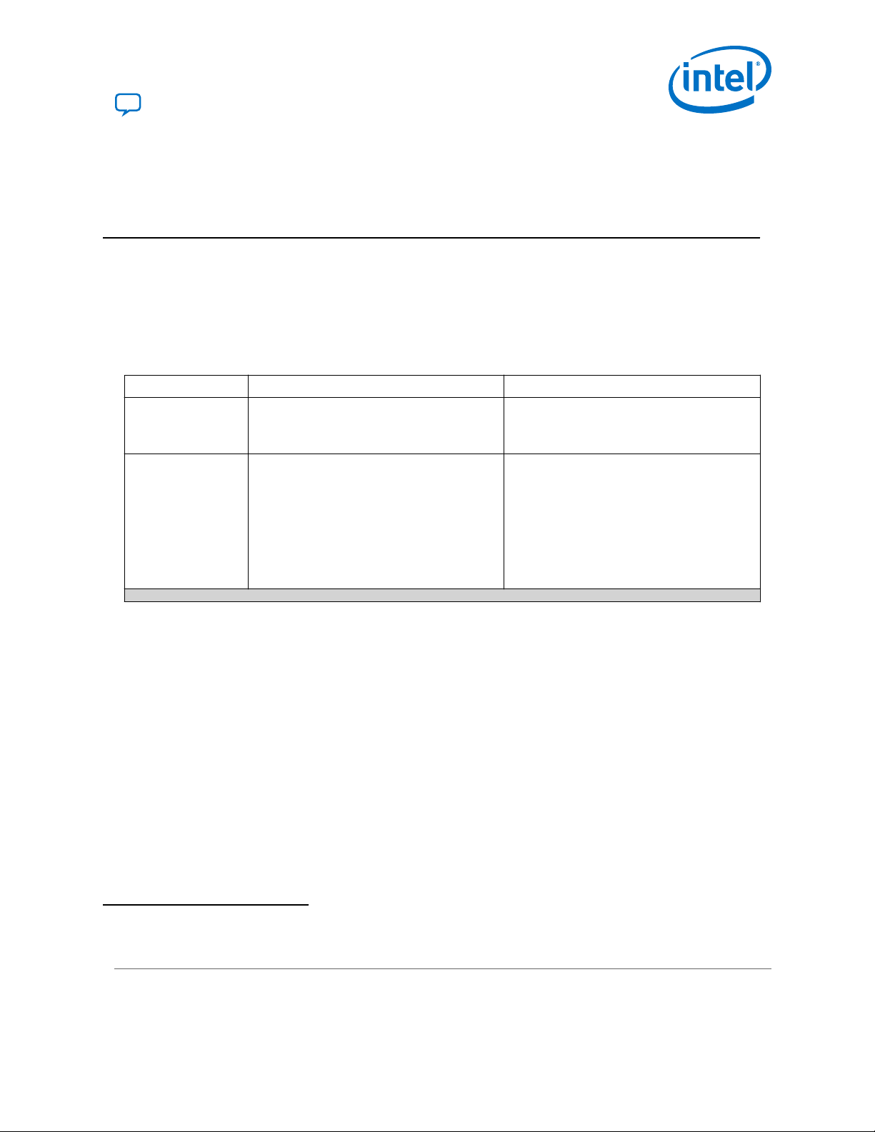
2.1.1.1. Combinational Custom Instruction Ports
A combinational custom instruction must have a result port, and may have optional
dataa and datab ports.
Figure 3. Combinational Custom Instruction Block Diagram
In the figure above, the dataa and datab ports are inputs to the logic block, which
drives the results on the result port. Because the logic function completes in a single
clock cycle, a combinational custom instruction does not require control ports.
Table 2. Combinational Custom Instruction Ports
Port Name Direction Required Description
dataa[31:0]
datab[31:0]
result[31:0]
Input No Input operand to custom instruction
Input No Input operand to custom instruction
Output Yes Result of custom instruction
The only required port for combinational custom instructions is the result port. The
dataa and datab ports are optional. Include them only if the custom instruction
requires input operands. If the custom instruction requires only a single input port,
use dataa.
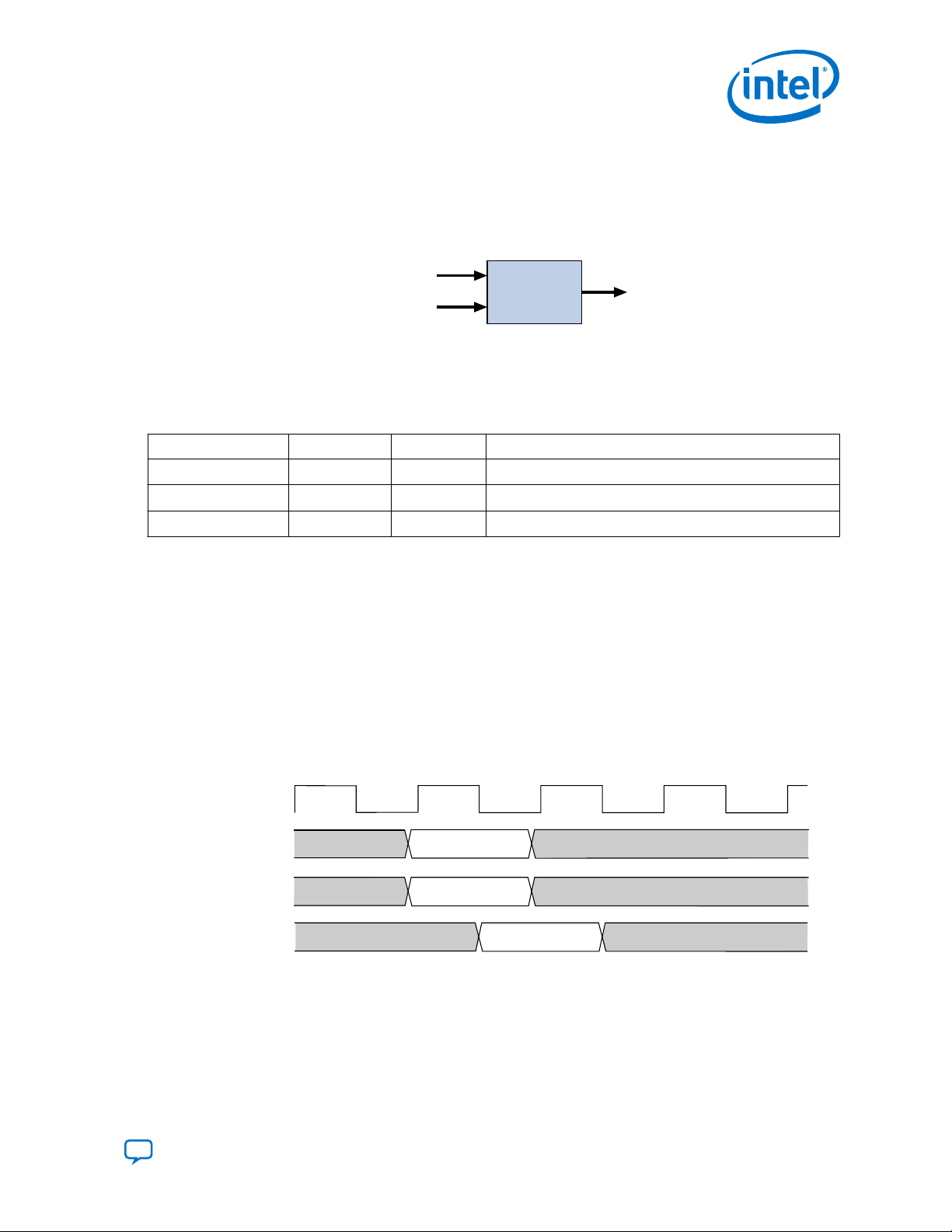
2.1.1.2. Combinational Custom Instruction Timing
The processor presents the input data on the dataa and datab ports on the rising
edge of the processor clock. The processor reads the result port on the rising edge
of the following processor clock cycle.
Figure 4. Combinational Custom Instruction Timing Diagram
Related Information
Combinational Custom Instruction Ports on page 9
Block diagram showing the dataa, datab, and result ports
Send Feedback
Nios II Custom Instruction User Guide
9
Page 10
2.1.2. Multicycle Custom Instructions
dataa[31..0]
datab[31..0]
clk
clk_en
reset
start
Multi-cycle
done
result[31..0]
Multicycle (sequential) custom instructions consist of a logic block that requires two or
more clock cycles to complete an operation.
Figure 5. Multicycle Custom Instruction Block Diagram
Multicycle custom instructions complete in either a fixed or variable number of clock
cycles. For a custom instruction that completes in a fixed number of clock cycles, you
specify the required number of clock cycles at system generation. For a custom
instruction that requires a variable number of clock cycles, you instantiate the start
and done ports. These ports participate in a handshaking scheme to determine when
the custom instruction execution is complete.
2. Custom Instruction Hardware Interface
UG-20286 | 2020.04.27
A basic multicycle custom instruction block, with the required ports shown in "Custom
Instruction Types", implements a single custom operation. This operation has a
selection index determined when the instruction is instantiated in the system using
Platform Designer.
You can further optimize multicycle custom instructions by implementing the extended
internal register file, or by creating external interface custom instructions.
Related Information
• Extended Custom Instructions on page 11
• Internal Register File Custom Instructions on page 13
• External Interface Custom Instructions on page 15
• Custom Instruction Types on page 7
List of standard custom instruction hardware ports, to be used as signal types
2.1.2.1. Multicycle Custom Instruction Ports
Table 3. Multicycle Custom Instruction Ports
Port Name Direction Required Description
clk
clk_en
reset
start
done
Input Yes System clock
Input Yes Clock enable
Input Yes Synchronous reset
Input No Commands custom instruction logic to start execution
Output No Custom instruction logic indicates to the processor that execution is
complete
continued...
Nios II Custom Instruction User Guide
10
Send Feedback
Page 11
clk
dataa[]
datab[]
result[]
valid
valid
T0 T1 T3T2 T4 T5
T6
valid
done
clk_en
start
reset
2. Custom Instruction Hardware Interface
UG-20286 | 2020.04.27
Port Name Direction Required Description
dataa[31:0]
datab[31:0]
result[31:0]
The clk, clk_en, and reset ports are required for multicycle custom instructions.
The start, done, dataa, datab, and result ports are optional. Implement them
only if the custom instruction requires them.
The Nios II system clock feeds the custom logic block’s clk port, and the Nios II
system’s master reset feeds the active high reset port. The reset port is asserted
only when the whole Nios II system is reset.
The custom logic block must treat the active high clk_en port as a conventional clock
qualifier signal, ignoring clk while clk_en is deasserted.
Input No Input operand to custom instruction
Input No Input operand to custom instruction
Output No Result of custom instruction
2.1.2.2. Multicycle Custom Instruction Timing
Figure 6. Multicycle Custom Instruction Timing Diagram
The processor asserts the active high start port on the first clock cycle of the custom
instruction execution. At this time, the dataa and datab ports have valid values and
remain valid throughout the duration of the custom instruction execution. The start
signal is asserted for a single clock cycle.
For a fixed length multicycle custom instruction, after the instruction starts, the
processor waits the specified number of clock cycles, and then reads the value on the
result signal. For an n-cycle operation, the custom logic block must present valid
data on the nth rising edge after the custom instruction begins execution.
For a variable length multicycle custom instruction, the processor waits until the active
high done signal is asserted. The processor reads the result port on the same clock
edge on which done is asserted. The custom logic block must present data on the
result port on the same clock cycle on which it asserts the done signal.
2.1.3. Extended Custom Instructions
Send Feedback
An extended custom instruction allows a single custom logic block to implement
several different operations.
Nios II Custom Instruction User Guide
11
Page 12
dataa[31..0]
0
1
2
n[1..0]
result[31..0]
bit-swap
operation
byte-swap
operation
Custom
Instruction
half-word-swap
operation
2. Custom Instruction Hardware Interface
Extended custom instruction components occupy multiple select indices. The selection
indices are determined when the custom instruction hardware block is instantiated in
the system using Platform Designer.
Extended custom instructions use an extension index to specify which operation the
logic block performs. The extension index can be up to eight bits wide, allowing a
single custom logic block to implement as many as 256 different operations.
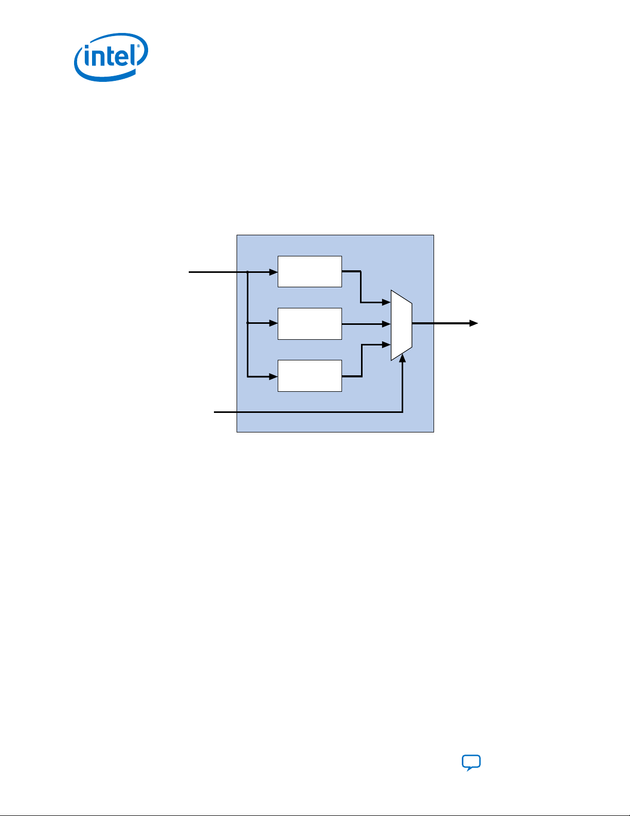
The following block diagram shows an extended custom instruction with bit-swap,
byte-swap, and half-word swap operations.
Figure 7. Extended Custom Instruction with Swap Operations
UG-20286 | 2020.04.27
The custom instruction in the preceding figure performs swap operations on data
received at the dataa port. The instruction hardware uses the two bit wide n port to
select the output from a multiplexer, determining which result is presented to the
result port.
Note: This logic is just a simple example, using a multiplexer on the output. You can
implement function selection based on an extension index in any way that is
appropriate for your application.
Extended custom instructions can be combinational or multicycle custom instructions.
To implement an extended custom instruction, add an n port to your custom
instruction logic. The bit width of the n port is a function of the number of operations
the custom logic block can perform.
An extended custom instruction block occupies several contiguous selection indices.
When the block is instantiated, Platform Designer determines a base selection index.
When the Nios II processor decodes a custom instruction, the custom hardware
block's n port decodes the low-order bits of the selection index. Thus, the extension
index extends the base index to produce the complete selection index.
Nios II Custom Instruction User Guide
12
Send Feedback
Page 13

2. Custom Instruction Hardware Interface
UG-20286 | 2020.04.27
For example, suppose the custom instruction block in Figure 7 on page 12 is
instantiated in a Nios II system with a base selection index of 0x1C. In this case,
individual swap operations are selected with the following selection indices:
• 0x1C—Bit swap
• 0x1D—Byte swap
• 0x1E—Half-word swap
• 0x1F—reserved
Therefore, if n is <m> bits wide, the extended custom instruction component occupies
<m>
2
select indices.
For example, the custom instruction illustrated above occupies four indices, because n
is two bits wide. Therefore, when this instruction is implemented in a Nios II system,
256 - 4 = 252 available indices remain.
Related Information
Custom Instruction Assembly Language Interface on page 20
Information about the custom instruction index
2.1.3.1. Extended Custom Instruction Timing
All extended custom instruction port operations are identical to those for the
combinational and multicycle custom instructions, with the exception of the n port.
The n port timing is the same as that of the dataa port. For example, for an extended
variable multicycle custom instruction, the processor presents the extension index to
the n port on the same rising edge of the clock at which start is asserted, and the n
port remains stable during execution of the custom instruction.
The n port is not present in combinational and multicycle custom instructions.
2.1.4. Internal Register File Custom Instructions
The Nios II processor allows custom instruction logic to access its own internal register
file.
Internal register file access gives you the flexibility to specify whether the custom
instruction reads its operands from the Nios II processor’s register file or from the
custom instruction’s own internal register file. In addition, a custom instruction can
write its results to the local register file rather than to the Nios II processor’s register
file.
Custom instructions containing internal register files use readra, readrb, and
writerc signals to determine if the custom instruction should use the internal
register file or the dataa, datab, and result signals. Ports a, b, and c specify the
internal registers from which to read or to which to write. For example, if readra is
deasserted (specifying a read operation from the internal register), the a signal value
provides the register number in the internal register file. Ports a, b, and c are five bits
each, allowing you to address as many as 32 registers.
Send Feedback
Nios II Custom Instruction User Guide
13
Page 14

dataa[31..0]
datab[31..0]
writerc
result[31..0]
Multiplier
Adder
D Q
CLR
2. Custom Instruction Hardware Interface
Related Information
Instruction Set Reference
Further details about Nios II custom instruction implementation in the Nios II
Processor Reference Guide
2.1.4.1. Internal Register File Custom Instruction Example
Figure 8. Multiply-accumulate Custom Logic Block
UG-20286 | 2020.04.27
This example shows how a custom instruction can access the Nios II internal register
file.
When writerc is deasserted, the Nios II processor ignores the value driven on the
result port. The accumulated value is stored in an internal register. Alternatively, the
processor can read the value on the result port by asserting writerc. At the same
time, the internal register is cleared so that it is ready for a new round of multiply and
accumulate operations.
2.1.4.2. Internal Register File Custom Instruction Ports
To access the Nios II internal register file, you must implement several custom
instruction-specific ports.
The following table lists the internal register file custom instruction-specific optional
ports. Use the optional ports only if the custom instruction requires them.
Table 4. Internal Register File Custom Instruction Ports
Port Name Direction Required Description
readra
readrb
writerc
a[4:0]
b[4:0]
c[4:0]
Input No
Input No
Input No
Input No Custom instruction internal register number for data source A.
Input No Custom instruction internal register number for data source B.
Input No Custom instruction internal register number for data destination.
If readra is high, Nios II processor register a supplies dataa. If readra
is low, custom instruction logic reads internal register a.
If readrb is high, Nios II processor register b supplies datab. If readrb
is low, custom instruction logic reads internal register b.
If writerc is high, the Nios II processor writes the value on the result
port to register c. If writerc is low, custom instruction logic writes to
internal register c.
Nios II Custom Instruction User Guide
14
Send Feedback
Page 15
dataa[31..0]
datab[31..0]
clk
clk_en
reset
start
Conduit Interface
done
result[31..0]
2. Custom Instruction Hardware Interface
UG-20286 | 2020.04.27
The readra, readrb, writerc, a, b, and c ports behave similarly to dataa. When
the custom instruction begins, the processor presents the new values of the readra,
readrb, writerc, a, b, and c ports on the rising edge of the processor clock. All six
of these ports remain stable during execution of the custom instructions.
To determine how to handle the register file, custom instruction logic reads the active
high readra, readrb, and writerc ports. The logic uses the a, b, and c ports as
register numbrs. When readra or readrb is asserted, the custom instruction logic
ignores the corresponding a or b port, and receives data from the dataa or datab
port. When writerc is asserted, the custom instruction logic ignores the c port and
writes to the result port.
All other custom instruction port operations behave the same as for combinational and
multicycle custom instructions.
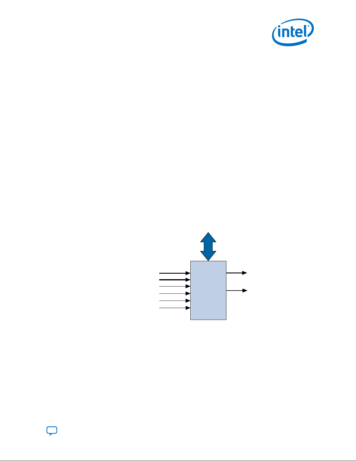
2.1.5. External Interface Custom Instructions
Nios II external interface custom instructions allow you to add an interface to
communicate with logic outside of the processor’s datapath.
At system generation, conduits propagate out to the top level of the Platform Designer
system, where external logic can access the signals. By enabling custom instruction
logic to access memory external to the processor, external interface custom
instructions extend the capabilities of the custom instruction logic.
Figure 9. Custom Instruction with External Interface
Custom instruction logic can perform various tasks such as storing intermediate
results or reading memory to control the custom instruction operation. The conduit
interface also provides a dedicated path for data to flow into or out of the processor.
For example, custom instruction logic with an external interface can feed data directly
from the processor’s register file to an external first-in first-out (FIFO) memory buffer.
Send Feedback
Nios II Custom Instruction User Guide
15
Page 16

UG-20286 | 2020.04.27
Send Feedback
3. Custom Instruction Software Interface
The Nios II custom instruction software interface abstracts logic implementation
details from the application code.
During the build process the Nios II software build tools generate macros that allow
easy access from application code to custom instructions.
3.1. Custom Instruction Software Examples
These examples illustrate how the Nios II custom instruction software interface fits
into your software code.
The following example shows a portion of the system.h header file that defines a
macro for a bit-swap custom instruction. This bit-swap example accepts one 32 bit
input and performs only one function.
#define ALT_CI_BITSWAP_N 0x00
#define ALT_CI_BITSWAP(A) __builtin_custom_ini(ALT_CI_BITSWAP_N,(A))
In this example, ALT_CI_BITWSWAP_N is defined to be 0x0, which is the custom
instruction’s selection index. The ALT_CI_BITSWAP(A) macro accepts a single
argument, abstracting out the selection index ALT_CI_BITWSWAP_N. The macro maps
to a GNU Compiler Collection (GCC) Nios II built-in function.
The next example illustrates application code that uses the bit-swap custom
instruction.
#include "system.h"
int main (void)
{
int a = 0x12345678;
int a_swap = 0;
a_swap = ALT_CI_BITSWAP(a);
return 0;
}
The code in this example includes the system.h file to enable the application software
to use the custom instruction macro definition. The example code declares two
integers, a and a_swap. Integer a is passed as input to the bit swap custom
instruction and the results are loaded in a_swap.
The example above illustrates how most applications use custom instructions. The
macros defined by the Nios II software build tools use C integer types only.
Occasionally, applications require input types other than integers. In those cases, you
can use a custom instruction macro to process non-integer return values.
Intel Corporation. All rights reserved. Agilex, Altera, Arria, Cyclone, Enpirion, Intel, the Intel logo, MAX, Nios,
Quartus and Stratix words and logos are trademarks of Intel Corporation or its subsidiaries in the U.S. and/or
other countries. Intel warrants performance of its FPGA and semiconductor products to current specifications in
accordance with Intel's standard warranty, but reserves the right to make changes to any products and services
at any time without notice. Intel assumes no responsibility or liability arising out of the application or use of any
information, product, or service described herein except as expressly agreed to in writing by Intel. Intel
customers are advised to obtain the latest version of device specifications before relying on any published
information and before placing orders for products or services.
*Other names and brands may be claimed as the property of others.
ISO
9001:2015
Registered
Page 17

3. Custom Instruction Software Interface
UG-20286 | 2020.04.27
Note: You can define custom macros for Nios II custom instructions that allow other 32 bit
input types to interface with custom instructions.
Related Information
Built-in Functions and User-defined Macros on page 17
More information about the GCC built-in functions
3.2. Built-in Functions and User-defined Macros
The Nios II processor uses GCC built-in functions to map to custom instructions.
By default, the integer type custom instruction is defined in a system.h file. However,
by using built-in functions, software can use 32 bit non-integer types with custom
instructions. Fifty-two built-in functions are available to accommodate the different
combinations of supported types.
Built-in function names have the following format:
__builtin_custom_<return type>n<parameter types>
<return type> and <parameter types> represent the input and output types, encoded
as follows:
•
i—int
•
f—float
•
p—void *
•
(empty)—void
The following example shows the prototype definitions for two built-in functions.
void __builtin_custom_nf (int n, float dataa);
float __builtin_custom_fnp (int n, void * dataa);
n is the selection index. The built-in function __builtin_custom_nf() accepts a
float as an input, and does not return a value. The built-in
function__builtin_custom_fnp() accepts a pointer as input, and returns a float.
To support non-integer input types, define macros with mnemonic names that map to
the specific built-in function required for the application.
The following example shows user-defined custom instruction macros used in an
application.
1. /* define void udef_macro1(float data); */
2. #define UDEF_MACRO1_N 0x00
3. #define UDEF_MACRO1(A) __builtin_custom_nf(UDEF_MACRO1_N, (A));
4. /* define float udef_macro2(void *data); */
5. #define UDEF_MACRO2_N 0x01
6. #define UDEF_MACRO2(B) __builtin_custom_fnp(UDEF_MACRO2_N, (B));
7.
8. int main (void)
9. {
10. float a = 1.789;
11. float b = 0.0;
12. float *pt_a = &a;
13.
14. UDEF_MACRO1(a);
15. b = UDEF_MACRO2((void *)pt_a);
Send Feedback
Nios II Custom Instruction User Guide
17
Page 18

16. return 0;
17. }
On lines 2 through 6, the user-defined macros are declared and mapped to the
appropriate built-in functions. The macro UDEF_MACRO1() accepts a float as an
input parameter and does not return anything. The macro UDEF_MACRO2() accepts a
pointer as an input parameter and returns a float. Lines 14 and 15 show code that
uses the two user-defined macros.
Related Information
• GCC, the GNU Compiler Collection
More information about GCC built-in functions
• GCC Floating-point Custom Instruction Support Overview
• GCC Single-precision Floating-point Custom Instruction Command Line
3.2.1. Built-in Functions with No Return Value
The following built-in functions in the Nios II GCC compiler have no return value. n
represents the custom instruction selection index, and dataa and datab represent
the input arguments, if any.
•
void __builtin_custom_n (int n);
•
void __builtin_custom_ni (int n, int dataa);
•
void __builtin_custom_nf (int n, float dataa);
•
void __builtin_custom_np (int n, void *dataa);
•
void __builtin_custom_nii (int n, int dataa, int datab);
•
void __builtin_custom_nif (int n, int dataa, float datab);
•
void __builtin_custom_nip (int n, int dataa, void *datab);
•
void __builtin_custom_nfi (int n, float dataa, int datab);
•
void __builtin_custom_nff (int n, float dataa, float datab);
•
void __builtin_custom_nfp (int n, float dataa, void *datab);
•
void __builtin_custom_npi (int n, void *dataa, int datab);
•
void __builtin_custom_npf (int n, void *dataa, float datab);
•
void __builtin_custom_npp (int n, void *dataa, void *datab);
3. Custom Instruction Software Interface
UG-20286 | 2020.04.27
3.2.2. Built-in Functions that Return a Value of Type Int
The following built-in functions in the Nios II GCC compiler return a value of type int.
n represents the custom instruction selection index, and dataa and datab represent
the input arguments, if any.
•
int __builtin_custom_in (int n);
•
int __builtin_custom_ini (int n, int dataa);
•
int __builtin_custom_inf (int n, float dataa);
•
int __builtin_custom_inp (int n, void *dataa);
Nios II Custom Instruction User Guide
18
Send Feedback
Page 19

3. Custom Instruction Software Interface
UG-20286 | 2020.04.27
•
int __builtin_custom_inii (int n, int dataa, int datab);
•
int __builtin_custom_inif (int n, int dataa, float datab);
•
int __builtin_custom_inip (int n, int dataa, void *datab);
•
int __builtin_custom_infi (int n, float dataa, int datab);
•
int __builtin_custom_inff (int n, float dataa, float datab);
•
int __builtin_custom_infp (int n, float dataa, void *datab);
•
int __builtin_custom_inpi (int n, void *dataa, int datab);
•
int __builtin_custom_inpf (int n, void *dataa, float datab);
•
int __builtin_custom_inpp (int n, void *dataa, void *datab);
3.2.3. Built-in Functions that Return a Value of Type Float
The following built-in functions in the Nios II GCC compiler return a value of type
float. n represents the custom instruction selection index, and dataa and datab
represent the input arguments, if any.
•
float __builtin_custom_fn (int n);
•
float __builtin_custom_fni (int n, int dataa);
•
float __builtin_custom_fnf (int n, float dataa);
•
float __builtin_custom_fnp (int n, void *dataa);
•
float __builtin_custom_fnii (int n, int dataa, int datab);
•
float __builtin_custom_fnif (int n, int dataa, float datab);
•
float __builtin_custom_fnip (int n, int dataa, void *datab);
•
float __builtin_custom_fnfi (int n, float dataa, int datab);
•
float __builtin_custom_fnff (int n, float dataa, float datab);
•
float __builtin_custom_fnfp (int n, float dataa, void *datab);
•
float __builtin_custom_fnpi (int n, void *dataa, int datab);
•
float __builtin_custom_fnpf (int n, void *dataa, float datab);
•
float __builtin_custom_fnpp (int n, void *dataa, void *datab);
3.2.4. Built-in Functions that Return a Pointer Value
The following built-in functions in the Nios II GCC compiler return a pointer value. n
represents the custom instruction selection index, and dataa and datab represent
the input arguments, if any.
•
void *__builtin_custom_pn (int n);
•
void *__builtin_custom_pni (int n, int dataa);
•
void *__builtin_custom_pnf (int n, float dataa);
•
void *__builtin_custom_pnp (int n, void *dataa);
•
void *__builtin_custom_pnii (int n, int dataa, int datab);
•
void *__builtin_custom_pnif (int n, int dataa, float datab);
Send Feedback
Nios II Custom Instruction User Guide
19
Page 20

3. Custom Instruction Software Interface
•
void *__builtin_custom_pnip (int n, int dataa, void *datab);
•
void *__builtin_custom_pnfi (int n, float dataa, int datab);
•
void *__builtin_custom_pnff (int n, float dataa, float datab);
•
void *__builtin_custom_pnfp (int n, float dataa, void *datab);
•
void *__builtin_custom_pnpi (int n, void *dataa, int datab);
•
void *__builtin_custom_pnpf (int n, void *dataa, float datab);
•
void *__builtin_custom_pnpp (int n, void *dataa, void *datab);
3.3. Custom Instruction Assembly Language Interface
The Nios II custom instructions are accessible in assembly code as well as C/C++.
3.3.1. Custom Instruction Assembly Language Syntax
Nios II custom instructions use a standard assembly language syntax:
custom <selection index>, <Destination>, <Source A>, <Source B>
• <selection index>—The 8-bit number that selects the particular custom instruction
•
<Destination>—Identifies the register where the result from the result port (if
any) will be placed
• <Source A>—Identifies the register that provides the first input argument from
the dataa port (if any)
• <Source B>—Identifies the register that provides the first input argument from
the datab port (if any)
UG-20286 | 2020.04.27
You designate registers in one of two formats, depending on whether you want the
custom instruction to use a Nios II register or an internal register:
•
r<i>—Nios II register <i>
•
c<i>—Custom register <i> (internal to the custom instruction component)
The use of r or c controls the readra, readrb, and writerc fields in the the custom
instruction word.
Custom registers are only available with internal register file custom instructions.
Related Information
Custom Instruction Word Format on page 21
Detailed information about instruction fields and register file selection
3.3.2. Custom Instruction Assembly Language Examples
These examples demonstrate the syntax for custom instruction assembly language
calls.
custom 0, r6, r7, r8
Nios II Custom Instruction User Guide
20
Send Feedback
Page 21

31 30 29 28 27 26 25 24 23 22 21 20 19 18 17 16 15 14 13 12 11 10 9 8 7 6 5 4 3 2 1 0
NC
BA
OP=0x32
writerc
readrb
readra
3. Custom Instruction Software Interface
UG-20286 | 2020.04.27
The example above shows a call to a custom instruction with selection index 0. The
input to the instruction is the current contents of the Nios II processor registers r7
and r8, and the results are stored in the Nios II processor register r6.
custom 3, c1, r2, c4
The example above shows a call to a custom instruction with selection index 3. The
input to the instruction is the current contents of the Nios II processor register r2 and
the custom register c4, and the results are stored in custom register c1.
custom 4, r6, c9, r2
The example above shows a call to a custom instruction with selection index 4. The
input to the instruction is the current contents of the custom register c9 and the Nios
II processor register r2, and the results are stored in Nios II processor register r6.
Related Information
custom
More information about the binary format of custom instructions in the Nios II
Processor Reference Guide
3.3.3. Custom Instruction Word Format
Custom instructions are R-type instructions.
The instruction word specifies the 8-bit custom instruction selection index and register
usage.
Figure 10. Custom Instruction Word Format
Table 5. Custom Instruction Fields
Field Name Purpose Corresponding Signal
A
B
C
readra
readrb
writerc
N
OP custom opcode, 0x32
Register address of input operand A
Register address of input operand B
Register address of output operand C
Register file selector for input operand A
Register file selector for input operand B
Register file selector for ouput operand C
Custom instruction select index (optionally includes an
extension index)
readra
readrb
writerc
n/a
Send Feedback
Nios II Custom Instruction User Guide
21
Page 22

The register file selectors determine whether the custom instruction component
7 wn wn-1 0
N
wn = width of n
. . .
. . .
n
accesses Nios II processor registers or custom registers, as follows:
Table 6. Register File Selection
3. Custom Instruction Software Interface
UG-20286 | 2020.04.27
Register File Selector
Value
0 Custom instruction component internal register file
1 Nios II processor register file
Related Information
• R-Type
Information about R-type instructions in the Nios II Processor Reference Guide
• custom
More information about the binary format of custom instructions in the Nios II
Processor Reference Guide
3.3.3.1. Select Index Field (N)
The custom instruction N field, bits 13:6, is the custom instruction select index. The
select index determine which custom instruction executes.
The Nios II processor supports up to 256 distinct custom instructions through the
custom opcode. A custom instruction component can implement a single instruction,
or multiple instructions.
In the case of a simple (non-extended) custom instruction, the select index is a simple
8-bit value, assigned to the custom instruction block when it is instantiated in Platform
Designer.
Components that implement multiple instructions possess an n port, as described in
"Extended Custom Instructions". The n port implements an extension index, which is a
subfield of the select index, as shown in the following figure.
Register File
Figure 11. Select Index Format
Note:
Do not confuse N, the selection index field of the custom instruction, with n, the
extension index port. Although n can be 8 bits wide, it generally corresponds to the
low-order bits of N.
Related Information
Extended Custom Instructions on page 11
Nios II Custom Instruction User Guide
22
Send Feedback
Page 23

UG-20286 | 2020.04.27
Send Feedback
4. Design Example: Cyclic Redundancy Check
The cyclic redundancy check (CRC) algorithm is a useful example of a Nios II custom
instruction.
The CRC algorithm detects the corruption of data during transmission. It detects a
higher percentage of errors than a simple checksum. The CRC calculation consists of
an iterative algorithm involving XOR and shift operations. These operations are carried
out concurrently in hardware and iteratively in software. Because the operations are
carried out concurrently, the execution is much faster in hardware.
The CRC design files demonstrate the steps to implement an extended multicycle Nios
II custom instruction.
Related Information
• Nios II Custom Instruction Design Example
Downloadable design files
• Design Example: Use of custom instruction for the NIOS II processor in Intel
Cyclone® 10 LP devices.
®
4.1. Building the CRC Example Hardware
You use the Platform Designer component editor to instantiate a Nios II custom
instruction based on your custom hardware. The Platform Designer component editor
enables you to create new components, including Nios II custom instructions.
Implementing a Nios II custom instruction involves using the custom instruction tool
flow.
Implementing a Nios II custom instruction hardware entails the following tasks:
1. Opening the component editor
2. Specify the custom instruction component type
3. Displaying the custom instruction block symbol
4. Adding the HDL files
5. Configuring the custom instruction parameter type
6. Setting up the custom instruction interfaces
7. Configuring the custom instruction signal type
8. Saving and adding the custom instruction
9. Generating the system and compiling in the Intel® Quartus® Prime software
Intel Corporation. All rights reserved. Agilex, Altera, Arria, Cyclone, Enpirion, Intel, the Intel logo, MAX, Nios,
Quartus and Stratix words and logos are trademarks of Intel Corporation or its subsidiaries in the U.S. and/or
other countries. Intel warrants performance of its FPGA and semiconductor products to current specifications in
accordance with Intel's standard warranty, but reserves the right to make changes to any products and services
at any time without notice. Intel assumes no responsibility or liability arising out of the application or use of any
information, product, or service described herein except as expressly agreed to in writing by Intel. Intel
customers are advised to obtain the latest version of device specifications before relying on any published
information and before placing orders for products or services.
*Other names and brands may be claimed as the property of others.
ISO
9001:2015
Registered
Page 24

4. Design Example: Cyclic Redundancy Check
UG-20286 | 2020.04.27
Related Information
• Creating Platform Designer Components
Detailed information about the Platform Designer component editor in the
Quartus Prime Pro Edition Handbook Volume 1: Design and Synthesis
• Creating Platform Designer Components
Detailed information about the Platform Designer component editor in the
Quartus Prime Standard Edition Handbook Volume 1: Design and Synthesis.
4.1.1. Setting up the Environment for the CRC Example Design
Before you start the design example, you must set up the design environment to
accommodate the custom instruction implementation process.
To set up the design example environment, follow these steps:
1. Download the ug_custom_instruction_files.zip file from the Nios II Custom
Instruction Design Example web page.
2. Open the ug_custom_instruction_files.zip file and extract all the files to a new
directory.
3. Follow the instructions in the Intel Quartus Prime Project Setup section in the
readme_qsys.txt file in the extracted design files. The instructions direct you to
determine a <project_dir> working directory for the project and to open the
design example project in the Intel Quartus Prime software.
Related Information
Nios II Custom Instruction Design Example
Downloadable design files
4.1.2. Opening the Component Editor
After you finish setting up the design environment, you can open Platform Designer
and the component editor.
Before performing this task, you must perform the steps in “Setting up the
Environment for the CRC Example Design”. After performing these steps, you have an
Intel Quartus Prime project located in the <project_dir> directory and open in the
Intel Quartus Prime software.
To open the component editor, follow these steps:
1. To open Platform Designer, on the Tools menu, click Platform Designer.
2. In Platform Designer, on the File menu, click Open.
3. Browse to the <project_dir> directory if necessary, select the .qsys file, and click
Open.
4. On the Platform Designer Component Library tab, click New. The component
editor appears, displaying the Introduction tab.
Related Information
Setting up the Environment for the CRC Example Design on page 24
Instructions for setting up the design environment
Nios II Custom Instruction User Guide
24
Send Feedback
Page 25

4. Design Example: Cyclic Redundancy Check
UG-20286 | 2020.04.27
4.1.3. Specifying the Custom Instruction Component Type
To specify the custom instruction component type, you specify a name, a display
name, a version, and optionally a group, description (recommended), creator, and
icon. These steps help define the _hw.tcl file for the new custom component.
First, make sure that the component editor displays the Component Type tab.
To specify the initial details in the custom instruction parameter editor, follow these
steps:
1.
For Name and for Display Name, type CRC.
2.
For Version, type 1.0.
3. Leave the Group field blank.
4. Optionally, set the Description, Created by, and Icon fields as you prefer.
Figure 12. Setting Custom Instruction Name and Version
Send Feedback
Nios II Custom Instruction User Guide
25
Page 26

4. Design Example: Cyclic Redundancy Check
4.1.4. Displaying the Custom Instruction Block Symbol
Click Next to display the custom component in the Block Symbol tab.
Figure 13. Viewing the Custom Instruction as a Block Symbol
UG-20286 | 2020.04.27
4.1.5. Adding the CRC Custom Instruction HDL Files
To specify the synthesis HDL files for your custom instruction, you browse to the HDL
logic definition files in the design example.
To specify the synthesis files, follow these steps:
1. Click Next to display the Files tab.
2. Under Synthesis Files, click Add Files.
3.
Browse to <project_dir>/crc_hw, the location of the HDL files for this design
example.
4. Select the CRC_Custom_Instruction.v and CRC_Component.v files and click
Open.
Nios II Custom Instruction User Guide
26
Send Feedback
Page 27

4. Design Example: Cyclic Redundancy Check
UG-20286 | 2020.04.27
Figure 14. Browsing to Custom Instruction HDL Files
5. Open the File Attributes dialog box by double-clicking the Attributes column in
Send Feedback
Note: The Intel Quartus Prime Analysis and Synthesis program checks the design
for errors when you add the files. Confirm that no error message appears.
the CRC_Custom_Instruction.v line.
Nios II Custom Instruction User Guide
27
Page 28

Figure 15. File Attributes Dialog Box
4. Design Example: Cyclic Redundancy Check
UG-20286 | 2020.04.27
6. In the File Attributes dialog box, turn on the Top-level File attribute, as shown
in the figure above. This attribute indicates that CRC_Custom_Instruction.v is
the top-level HDL file for this custom instruction.
7. Click OK.
Note: The Intel Quartus Prime Analysis and Synthesis program checks the design
for errors when you select a top-level file. Confirm that no error message
appears.
8. Click Analyze Synthesis Files to synthesize the top-level file.
9. To simulate the system with the ModelSim* - Intel FPGA Edition simulator, you can
add your simulation files under Verilog Simulation Files or VHDL Simulation
Files in the in the Files tab.
4.1.6. Configuring the Custom Instruction Parameter Type
To configure the custom instruction parameter type, follow these steps:
1.
Click Next to display the Parameters tab. The parameters in the .v files are
displayed.
Nios II Custom Instruction User Guide
28
Send Feedback
Page 29

4. Design Example: Cyclic Redundancy Check
UG-20286 | 2020.04.27
Figure 16. Custom Instruction Parameters
The Editable checkbox next to each parameter indicates whether the parameter
will appear in the custom component's parameter editor. By default, all
parameters are editable.
2. To remove a parameter from the custom instruction parameter editor, you can
turn off Editable next to the parameter. For the CRC example, you can leave all
parameters editable.
When Editable is off, the user cannot see or control the parameter, and it is set to
the value in the Default Value column. When Editable is on, the user can control
the parameter value, and it defaults to the value in the Default Value column.
3. To see a preview of the custom component's parameter editor, you can click
Preview the GUI.
4.1.7. Setting Up the CRC Custom Instruction Interfaces
To set up the custom instruction interfaces, you use the Interfaces tab.
To set up the custom instruction interfaces, follow these steps:
1. In the View menu, click Interfaces to display the Interfaces tab.
Send Feedback
Nios II Custom Instruction User Guide
29
Page 30

Figure 17. Opening the Interfaces Tab
2. If the Remove Interfaces With No Signals button is active, click it.
3. Ensure that a single interface remains, with Name set to the name in the Signals
tab. For the design example, maintain the interface name
nios_custom_instruction_slave.
4. Ensure the Type for this interface is Custom Instruction Slave.
5. For Clock Cycles, type 0. This is the correct value for a variable multicycle type
custom instruction, such as the CRC module in the design example. For other
designs, use the correct number of clock cycles for your custom instruction logic.
6.
For Operands, type 1, because the CRC custom instruction has one operand. For
other designs, type the number of operands used by your custom instruction.
Note: If you rename an interface by changing the value in the Name field, the
Signals tab Interface column value changes automatically. The value
shown in the block diagram updates when you change tabs and return to
the Interfaces tab.
Note:
If the interface includes a done signal and a clk signal, the component
editor infers that the interface is a variable multicycle type custom
instruction interface, and sets the value of Clock Cycles to 0.
4. Design Example: Cyclic Redundancy Check
UG-20286 | 2020.04.27
4.1.7.1. Specifying Additional Interfaces
You can specify additional interfaces in the Interfaces tab.
You can specify additional interfaces if your custom instruction logic requires special
interfaces, either to the Avalon®-Memory Mapped fabric or outside the Platform
Designer system. The design example does not require additional interfaces.
Note: Most custom instructions use some combination of standard custom instruction ports,
such as dataa, datab, and result, and do not require additional interfaces.
The following instructions provide the information you need if a custom instruction in
your own design requires additional interfaces. You do not need these steps if you are
implementing the design example.
Nios II Custom Instruction User Guide
30
Send Feedback
Page 31

4. Design Example: Cyclic Redundancy Check
UG-20286 | 2020.04.27
To specify additional interfaces on the Interfaces tab, follow these steps:
1. Click Add Interface. The new interface has Custom Instruction Slave interface
type by default.
2. For Type, select the desired interface type.
3. Set the parameters for the newly created interface according to your system
requirements.
4.1.8. Configuring the Custom Instruction Signal Type
To configure the custom instruction signal type, follow these steps:
1. In the View menu, click Signals to open the Signals tab.
Figure 18. Custom Instruction Signal Types
2. For each signal in the list, follow these steps:
3. Open the Signals and Interfaces tab.
Send Feedback
a. Select the signal name.
b. In the Interface column, select the name of the interface to which you want
to assign the signal.
In the design example, select nios_custom_instruction_slave for all
signals. These selections ensure that the signals appear together on a single
interface, and that the interface corresponds to the design example files in the
crc_hw folder.
c. In the Signal Type column, select one of the standard hardware ports listed
in “Custom Instruction Types”. In the design example, each signal must be
mapped to the signal type of the same name.
Nios II Custom Instruction User Guide
31
Page 32

Figure 19. Signals and Interfaces
4. Design Example: Cyclic Redundancy Check
UG-20286 | 2020.04.27
The parameters for Clock Cycle Type automatically change to "Variable" because
the design example builds a variable multicycle type custom instruction. For other
designs, you enter the correct clock cycle type for your custom instruction design:
• "Variable" for a variable multicycle type custom instruction
• "Multicycle" for a fixed multicycle type custom instruction
• "Combinatorial" for a combinational type custom instruction.
If the interface does not include a clk signal, the component editor automatically
infers that the interface is a combinational type interface. If the interface includes
a clk signal, the component editor automatically infers that the interface is a
multicycle interface. If the interface does not include a done signal, the
component editor infers that the interface is a fixed multicycle type interface. If
the interface includes a done signal, the component editor infers that the interface
is a variable multicycle type interface.
Related Information
Custom Instruction Types on page 7
List of standard custom instruction hardware ports, to be used as signal types
4.1.9. Saving and Adding the CRC Custom Instruction
To save the custom instruction and add it to your Nios II processor, follow these steps:
1. Click Finish. A dialog box prompts you to save your changes before exiting.
2. Click Yes, Save. The new custom instruction appears in the Platform Designer
Component Library.
3. In the Platform Designer Component Library, under Library, select CRC, the new
custom instruction you created in the design example.
Nios II Custom Instruction User Guide
32
Send Feedback
Page 33

4. Design Example: Cyclic Redundancy Check
UG-20286 | 2020.04.27
4. Click Add to add the new instruction to the Platform Designer system.
Platform Designer automatically assigns an unused selection index to the new
custom instruction. You can see this index in the System Contents tab, in the
Base column, in the form "Opcode <N>". <N> is represented as a decimal
number. The selection index is exported to system.h when you generate the
system.
5. In the Connections panel, connect the new CRC_0 component’s
nios_custom_instruction_slave interface to the cpu component’s
custom_instruction_master interface.
6. Optional: You can change the custom instruction's selection index in the System
Contents tab. In the Base column across from the custom instruction slave, click
on "Opcode <N>", and type the desired selection index in decimal.
4.1.10. Generating and Compiling the CRC Example System
After you add the custom instruction logic to the system, you can generate the system
and compile it in the Intel Quartus Prime software.
To generate the system and compile, follow these steps:
1. In Platform Designer, on the Generation tab, turn on Create HDL design files
for synthesis.
2. Click Generate. System generation may take several seconds to complete.
3. After system generation completes, on the File menu, click Exit.
4. In the Intel Quartus Prime software, on the Project menu, click Add/Remove
Files in Project.
5. Ensure that the .qip file in the synthesis subdirectory is added to the project.
6. On the Processing menu, click Start Compilation.
Related Information
• Creating a System with Platform Designer
Detailed information about the Platform Designer Pro component editor in the
Quartus Prime Pro Edition Handbook Volume 1: Design and Synthesis.
• Creating a System with Platform Designer (Standard Edition)
For detailed information about the Platform Designer (Standard) component
editor, refer to "Creating a System with Platform Designer" in the Quartus
Prime Standard Edition Handbook Volume 1: Design and Synthesis.
4.2. Building the CRC Example Software
Next you create and build a new software project using the Nios II software build flow,
and run the software that accesses the custom instruction.
Creating the Software Project
The downloadable design files include the software source files. The following table
lists the CRC application software source files and their corresponding descriptions.
Send Feedback
Nios II Custom Instruction User Guide
33
Page 34

Table 7. CRC Application Software Source Files
File Name Description
crc_main.c
crc.c
crc.h Header file for crc.c.
ci_crc.c
ci_crc.h Header file for ci_crc.c.
Main program that populates random test data, executes the CRC both in software and with the
custom instruction, validates the output, and reports the processing time.
Software CRC algorithm run by the Nios II processor.
Program that accesses CRC custom instruction.
To run the application software, you must create an Executable and Linking Format
File (.elf) first. To create the .elf file, follow the instructions in the "Nios II Software
Build Flow" section in the readme_qsys.txt file in the extracted design files.
The application program runs three implementations of the CRC algorithm on the
same pseudo-random input data: an unoptimized software implementation, an
optimized software implementation, and the custom instruction CRC. The program
calculates the processing time and throughput for each of the versions, to
demonstrate the improved efficiency of a custom instruction compared to a software
implementation.
4. Design Example: Cyclic Redundancy Check
UG-20286 | 2020.04.27
4.2.1. Running and Analyzing the CRC Example Software
The following example shows the output from the application program run on a
Cyclone V E FPGA Development Kit with a 5CEFA7F31I7N speed grade device. This
example was created using the Intel Quartus Prime software v15.1 and Nios II
Embedded Design Suite (EDS) v15.1.
The output shows that the custom instruction CRC is 68 times faster than the
unoptimized CRC calculated purely in software and is 39 times faster than the
optimized version of the software CRC. The results you see using a different target
device and board may vary depending on the memory characteristics of the board and
the clock speed of the device, but these ratios are representative.
Nios II Custom Instruction User Guide
34
Send Feedback
Page 35

4. Design Example: Cyclic Redundancy Check
UG-20286 | 2020.04.27
4.2.1.1. Output of the CRC Design Example Software Run on a Cyclone V E FPGA Development Kit using the Intel Quartus Prime Software v15.1.
******************************************************************************
Comparison between software and custom instruction CRC32
******************************************************************************
System specification
-------------------System clock speed = 50 MHz
Number of buffer locations = 32
Size of each buffer = 256 bytes
Initializing all of the buffers with pseudo-random data
------------------------------------------------------Initialization completed
Running the software CRC
-----------------------Completed
Running the optimized software CRC
---------------------------------Completed
Running the custom instruction CRC
---------------------------------Completed
Validating the CRC results from all implementations
--------------------------------------------------All CRC implementations produced the same results
Processing time for each implementation
--------------------------------------Software CRC = 34 ms
Optimized software CRC = 19 ms
Custom instruction CRC = 00 ms
Processing throughput for each implementation
--------------------------------------------Software CRC = 2978 Mbps
Optimized software CRC = 32768 Mbps
Custom instruction CRC = 949 Mbps
Speedup ratio
------------Custom instruction CRC vs software CRC = 68
Custom instruction CRC vs optimized software CRC = 39
Optimized software CRC vs software CRC = 1
4.2.2. Using the User-defined Custom Instruction Macro
The design example software uses a user-defined macro to access the CRC custom
instruction.
The following example shows the macro that is defined in the ci_crc.c file.
#define CRC_CI_MACRO(n, A) \
__builtin_custom_ini(ALT_CI_CRC_CUSTOM_COMPONENT_0_N + (n & 0x7), (A))
This macro accepts a single int type input operand and returns an int type value.
The CRC custom instruction has extended type; the n value in the macro
CRC_CI_MACRO() indicates the operation to be performed by the custom instruction.
Send Feedback
Nios II Custom Instruction User Guide
35
Page 36

4. Design Example: Cyclic Redundancy Check
UG-20286 | 2020.04.27
ALT_CI_CRC_CUSTOM_COMPONENT_0_N is the custom instruction selection index for
the first instruction in the component. ALT_CI_CRC_CUSTOM_COMPONENT_0_N is
added to the value of n to calculate the selection index for a specific instruction. The n
value is masked because the n port of the custom instruction has only three bits.
To initialize the custom instruction, for example, you can add the initialization code in
the following example to your application software.
/* Initialize the custom instruction CRC to the initial remainder value: */
CRC_CI_MACRO (0,0);
For details of each operation of the CRC custom instruction and the corresponding
value of n, refer to the comments in the ci_crc.c file.
The examples above demonstrate that you can define the macro in your application to
accommodate your requirements. For example, you can determine the number and
type of input operands, decide whether to assign a return value, and vary the
extension index value, n. However, the macro definition and usage must be consistent
with the port declarations of the custom instruction. For example, if you define the
macro to return an int value, the custom instruction must have a result port.
Related Information
Custom Instruction Software Interface on page 16
Nios II Custom Instruction User Guide
36
Send Feedback
Page 37

UG-20286 | 2020.04.27
Send Feedback
5. Introduction to Nios® II Floating Point Custom Instructions
The Nios II architecture supports single precision floating point instructions with either
of two optional components:
• Floating point hardware 2
instructions as specified by the IEEE Std 754-2008 but with simplified, nonstandard rounding modes. The basic set of floating point custom instructions
includes single precision floating point addition, subtraction, multiplication,
division, square root, integer to float conversion, float to integer conversion,
minimum, maximum, negate, absolute, and comparisons.
• Floating point hardware (FPH1)—This component supports floating point
instructions as specified by the IEEE Std 754-1985. The basic set of floating point
custom instructions includes single-precision floating point addition, subtraction,
and multiplication. Floating point division is available as an extension to the basic
instruction set.
Note: For optimum performance and device footprint, Intel recommends using
FPH2 rather than FPH1.
(2)
(FPH2)—This component supports floating point
These floating point instructions are implemented as custom instructions. The table
below lists a detailed description of the conformance to the IEEE standards.
Table 8. Hardware Conformance with IEEE 754-1985 and IEEE 754-2008 Floating
Point Standard
Feature Floating Point Hardware
Operations Addition/
(2)
Second generation
Intel Corporation. All rights reserved. Agilex, Altera, Arria, Cyclone, Enpirion, Intel, the Intel logo, MAX, Nios,
Quartus and Stratix words and logos are trademarks of Intel Corporation or its subsidiaries in the U.S. and/or
other countries. Intel warrants performance of its FPGA and semiconductor products to current specifications in
accordance with Intel's standard warranty, but reserves the right to make changes to any products and services
at any time without notice. Intel assumes no responsibility or liability arising out of the application or use of any
information, product, or service described herein except as expressly agreed to in writing by Intel. Intel
customers are advised to obtain the latest version of device specifications before relying on any published
information and before placing orders for products or services.
*Other names and brands may be claimed as the property of others.
subtraction
Multiplication Implemented Implemented
Division Optional Implemented
Square root Not implemented, this operation is
Integer to float/
float to integer
Minimum/
maximum
Negate/absolute Not implemented, this operation is
Implementation with IEEE
754-1985
Implemented Implemented
implemented in software.
Not implemented, this operation is
implemented in software.
Not implemented, this operation is
implemented in software.
implemented in software.
Floating Point Hardware 2
Implementation with IEEE
754-2008
Implemented
Implemented
Implemented
Implemented
continued...
ISO
9001:2015
Registered
Page 38

5. Introduction to Nios® II Floating Point Custom Instructions
UG-20286 | 2020.04.27
Feature Floating Point Hardware
Implementation with IEEE
754-1985
Comparisons Not implemented, this operation is
Floating Point Hardware 2
Implementation with IEEE
754-2008
Implemented
implemented in software.
Precision Single Implemented Implemented
Exception
conditions
Double Not implemented. Double precision
operations are implemented in
software.
Invalid operation Result is Not a Number (NaN) Result is Not a Number (NaN)
Division by zero Result is ±infinity Result is ±infinity
Not implemented. Double precision
operations are implemented in
software.
Overflow Result is ±infinity Result is ±infinity
Inexact Result is a normal number Result is a normal number
Underflow Result is ±0 Result is ±0
Rounding Modes Round to nearest Implemented Implemented (roundTiesToAway mode)
Round toward
Not implemented Implemented (truncation mode)
zero
Round toward
Not implemented Not implemented
+infinity
Round toward –
Not implemented Not implemented
infinity
NaN Quiet Implemented No distinction is made between
Signaling Not implemented
signaling and quiet NaNs as input
operands. A result that produces a NaN
may produce either a signaling or quiet
NaN.
Subnormal
(denormalized)
numbers
Subnormal operands are treated as
zero. The FPH2 custom instructions do
not generate subnormal numbers.
• The comparison, minimum,
maximum, negate, and absolute
operations support subnormal
numbers.
• The add, subtract, multiply, divide,
square root, and float to integer
operations do NOT support
subnormal numbers. Subnormal
operands are treated as signed
zero. The FPH1 custom instructions
do not generate subnormal
numbers.
(3)
• The integer to float operation
cannot create subnormal numbers.
Software
exceptions
Status flags Not implemented. IEEE 754-1985
Not implemented. IEEE 754-1985
exception conditions are detected and
handled as described elsewhere in this
table.
exception conditions are detected and
handled as described elsewhere in this
table.
Not implemented. IEEE 754-2008
exception conditions are detected and
handled as described elsewhere in this
(3)
table.
Not implemented. IEEE 754-2008
exception conditions are detected and
handled as described elsewhere in this
(3)
table.
(3)
This operation is not fully compliant with IEEE 754-2008.
Nios II Custom Instruction User Guide
38
Send Feedback
Page 39

s 30 29 28 27 26 25 24 23 22 21 20 19 18 17 16 15 14 13 12 11 10 9 8 7 6 5 4 3
s EXP FRAC
®
5. Introduction to Nios
UG-20286 | 2020.04.27
II Floating Point Custom Instructions
Note: The FPH2 component also supports faithful rounding, which is not an IEEE 754-defined
rounding mode. Faithful rounding rounds results to either the upper or lower nearest
single-precision numbers. Therefore, the result produced is one of two possible values
and the choice between the two is not defined. The maximum error of faithful
rounding is 1 unit in the last place (ulp). Errors may not be evenly distributed.
5.1. Floating Point Background
5.2. IEEE 754 Format
The figure below shows the fields in an IEEE 754 32-bit single-precision value. The
table below provides a description of the fields. Normal single-precision floating point
numbers have the value (-1)
Figure 20. Single-Precision Format
Table 9. Single-Precision Field Descriptions
S
* 1.FRAC * 2
EXP -127
.
Mnemonic Name Description
FRAC Fraction Specifies the fractional portion (right of the binary point) of the mantissa.
EXP Biased Exponent Contains the exponent biased by the value 127. The biased exponent
S Sign Specifies the sign. 1 = negative, 0 = positive. Normal values, zero, infinity,
The integer value (left of the binary point) is always assumed to be 1 for
normal values so it is omitted. This omitted value is called the hidden bit.
The mantissa ranges from ≥1.0 to <2.0.
value 0x0 is reserved for zero and subnormal values. The biased exponent
value 0xff is reserved for infinity and NaN. The biased exponent ranges
from 1 to 0xfe for normal numbers (-126 to 127 when the bias is
subtracted out).
and subnormals are all signed. NaN has no sign, so the S field is ignored.
The IEEE 754 standard provides the following special values:
• Zero (EXP=0, FRAC=0)
• Subnormal (EXP=0, FRAC≠0)
• Infinity (EXP=255, FRAC=0)
• NaN (EXP=255, FRAC≠0)
Note: Zero, subnormal, and infinity are signed as specified by the S field. NaN has no sign so
the S field is ignored.
5.2.1. Unit in the Last Place
Unit in the last place (ULP) represents the value 2
1.192093e-07. The ULP is the distance between the closest straddling floating point
numbers a and b (a ≤ x ≤ b, a ≠ b), assuming that the exponent range is not upperbounded. The IEEE Round-to-Nearest modes produce results with a maximum error of
one-half ULP. The other IEEE rounding modes (Round-to-Zero, Round-to-PositiveInfinity, and Round-to-Negative-Infinity) produce results with a maximum error of one
ULP.
-23
, which is approximately
Send Feedback
Nios II Custom Instruction User Guide
39
Page 40

5. Introduction to Nios® II Floating Point Custom Instructions
UG-20286 | 2020.04.27
5.2.2. Floating Point Value Encoding
The table below shows how single-precision values are encoded across the 32-bit
range from 0x0000_0000 to 0xffff_ffff. Single-precision floating point numbers
have the following characteristics:
• Precision (ρ) = 24 bits (23 bits in FRAC plus one hidden bit)
• Radix (β) = 2
• e
• e
The most-significant bit of FRAC is 0 for signaling NaNs (sNaN) and 1 for quiet NaNs
(qNaN).
Table 10. Encoding of Values
Hexadecimal Value Name S EXP FRAC Value (Decimal)
0x0000_0000
0x0000_0001
0x007f_ffff
0x0080_0000
0x3f80_0000
0x4000_0000
0x7f7f_ffff
0x7f80_0000
0x7f80_0001
0x7fdf_ffff
0x7fe0_0000
0x7fff_ffff
0x8000_0000
0x8000_0001
0x807f_ffff
0x8080_0000
0xff7f_ffff
0xff80_0000
0xff80_0001
0xffdf_ffff
0xffe0_0000
0xffff_ffff
= -126
min
= 127
max
+0 0
min pos subnormal 0
max pos subnormal 0
min pos normal 0
1 0
2 0
max pos normal 0
+∞ 0
min sNaN (pos sign) 0
max sNaN (pos sign) 0
min qNaN (pos sign) 0
max qNaN (pos sign) 0
-0 1
max neg subnormal 1
min neg subnormal 1
max neg normal 1
min neg normal 1
-∞ 1
max sNaN (neg sign) 1
min sNaN (neg sign) 1
max qNaN (neg
sign)
min qNaN (neg sign) 1
0x00 0x00_0000
0x00 0x00_0001
0x00 0x7f_ffff
0x01 0x00_0000
0x7f 0x00_0000
0x80 0x00_0000
0xfe 0x7f_ffff
0xff 0x00_0000
0xff 0x00_0001
0xff 0x3f_ffff
0xff 0x40_0000
0xff 0x7f_ffff
0x00 0x00_0000
0x00 0x00_0001
0x00 0x7f_ffff
0x01 0x00_0000
0xfe 0x7f_ffff
0xff 0x00_0000
0xff 0x00_0001
0xff 0x3f_ffff
1
0xff 0x40_0000
0xff 0x7f_ffff
0.0
1.40129846e–45 (β
-126-24+1
2
1.1754942e-38
1.17549435e–38 (β
1.0 (1.0x20)
2.0 (1.0x21)
3.40282347e+38 ((β – β
emax
2
223) * 2
-0.0
-1.40129846e–45
-1.1754942e-38
-1.17549435e–38
-3.40282347e+38
= 2
= (2 – 2
127
-149
1-24
emin-ρ+1
)
emin
) * 2
= 2
1- ρ
127
=
-126
) *
= (2 –
)
Nios II Custom Instruction User Guide
40
Send Feedback
Page 41

®
5. Introduction to Nios
UG-20286 | 2020.04.27
II Floating Point Custom Instructions
5.3. Rounding Schemes
When the exact result of a floating point operation cannot be exactly represented as a
floating point value, it must be rounded.
The IEEE 754-2008 standard defines the default rounding mode to be “Round-toNearest RoundTiesToEven”. In the IEEE 754-1985 standard, this is called “Round-toNearest-Even”. Both standards also define additional rounding modes called “Roundto-Zero”, “Round-to-Negative-Infinity”, and “Round-to-Positive-Infinity”. The IEEE
754-2008 standard introduced a new optional rounding mode called “Round-toNearest RoundTiesAway”.
The FPH2 operations either support Nearest Rounding (RoundTiesAway), Truncation
Rounding, or Faithful Rounding. The type of rounding is a function of the operation and
is specified in Table 4-2. Because the software emulation library (used when floating
point hardware is not available) and FPH1 implement Round-to-Nearest
RoundTiesToEven, there can be differences in the results between FPH2 and these
other solutions.
5.3.1. Nearest Rounding
Nearest Rounding corresponds to the IEEE 754-2008 “Round-to-Nearest
RoundTiesAway” rounding mode. Nearest Rounding rounds the result to the nearest
single-precision number. When the result is halfway between two single-precision
numbers, the rounding chooses the upper number (larger values for positive results,
smaller value for negative results).
Nearest Rounding has a maximum error of one-half ULP. Errors are not evenly
distributed, because nearest rounding chooses the upper number more often than the
lower number when results are randomly distributed.
5.3.2. Truncation Rounding
Truncation Rounding corresponds to the IEEE 754-2008 “Round-To-Zero” rounding
mode. Truncation Rounding rounds results to the lower nearest single-precision
number.
Truncation Rounding has a maximum error of one ULP. Errors are not evenly
distributed.
5.3.3. Faithful Rounding
Faithful Rounding rounds results to either the upper or lower nearest single-precision
numbers. Therefore, Faithful Rounding produces one of two possible values. The
choice between the two is not defined.
Faithful Rounding has a maximum error of one ULP. Errors are not guaranteed to be
evenly distributed.
Note: Faithful Rounding mode is not defined by IEEE 754.
Send Feedback
Nios II Custom Instruction User Guide
41
Page 42
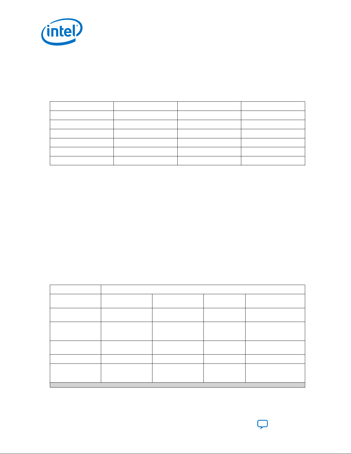
5. Introduction to Nios® II Floating Point Custom Instructions
5.3.4. Rounding Examples
The table below shows examples of the supported rounding schemes for decimal
values assuming rounded normalized decimal values with two digits of precision, like
one-digit integer or one-digit fraction.
Table 11. Decimal Rounding Examples
Unrounded Value Nearest Rounding Truncation Rounding Faithful Rounding
3.34 3.3 3.3 3.3 or 3.4
6.45 6.5 6.4 6.4 or 6.5
2.00 2.0 2.0 2.0 or 2.1
8.99 9.0 8.9 8.9 or 9.0
-1.24 -1.2 -1.2 -1.2 or -1.3
-3.78 -3.8 -3.7 -3.7 or -3.8
5.4. Special Floating Point Cases
The table below lists the results of some IEEE 754 special cases. The x represents a
normal value. The FPH2 are compliant for all of these cases.
UG-20286 | 2020.04.27
Results are assumed to be correctly signed so signs are omitted when they are not
important. When the sign is relevant, signs are shown with extra parenthesis around
the value such as (+∞). The value x in the table represents any non-NaN value.
Comparisons ignore the sign of zero for equality. For example, (-0) == (+0) and (+0)
≤ (-0). Comparisons that don’t include equality, like > and <, don’t consider -0 to be
less than +0. Comparisons return false if either or both inputs are NaN. The min and
max operations return the non-NaN input if one of their inputs is NaN and the other is
non-NaN. Other operations that produce floating point results return NaN if any or all
of their inputs are NaN.
Table 12. Special Cases
Operation Special Cases
fdivs 0/0=NaN ∞/∞=NaN 0/∞=0, ∞/0=∞ NaN/x=NaN, x/NaN=NaN,
fsubs (+∞)-(+∞)=NaN (-∞)-(-∞)=NaN (-0)-(-0)=+0 NaN-x=NaN, x-NaN=NaN,
fadds (+∞)+(-∞)=NaN (-∞)+(+∞)=NaN (+0)+(-0)=+0,
fmuls 0*∞=NaN ∞*0=NaN NaN*x=NaN, x*NaN=NaN,
fsqrts sqrt(-0) =-0 sqrt(x) =NaN, x<-0 sqrt(NAN) =NaN
int(>2fixsi &
round31-1)= 0x7fffffff,
int(+∞)=0x7fffffff
fixsiint(<-231)=
x80000000, int(∞)=0x80000000
(-0)+(+0)=+0
NaN/NaN=NaN
NaN-NaN=NaN
NaN+x=NaN, x
+NaN=NaN, NaN
+NaN=NaN
NaN*NaN=NaN
int(NaN)=undefined
continued...
Nios II Custom Instruction User Guide
42
Send Feedback
Page 43
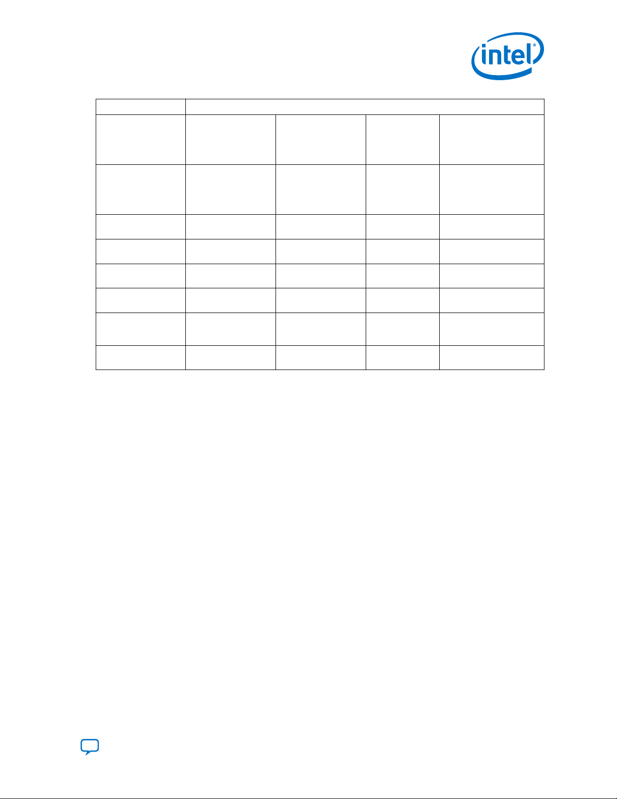
5. Introduction to Nios® II Floating Point Custom Instructions
UG-20286 | 2020.04.27
Operation Special Cases
fmins min((+0),(-0))=(-0) min((-0),(+0))=(-0) min(NaN,n)=x,
fmaxs max((+0),(-0))=(+0) max((-0),(+0))=(+0) max(NaN,x)=x,
fcmplts (<) (+∞)<(+∞)=0 (-∞)<(-∞)=0 (-0)<(+0)=0,
(+0)<(-0)=0
fcmples (≤) (+∞)≤(+∞)=1 (-∞)≤(-∞)=1 (+0)≤(-0)=1,
(-0)≤(+0)=1
fcmpgts (>) (+∞)>(+∞)=0 (-∞)>(-∞)=0 (-0)>(+0)=0,
(+0)>(-0)=0
fcmpges (≥) (+∞)≥(+∞)=1 (-∞)≥(-∞)=1 (-0)≥(+0)=1,
(+0)≥(-0)=1
fcmpeqs (=) (+∞)=(+∞)=1 (-∞)=(-∞)=1 (-0)=(+0)=1 (NaN==x)=0,
fcmpnes (≠) (+∞)≠ (+∞)=0 (-∞)≠ (-∞)=0 (-0)≠(+0)=0 NaN≠x=0, x≠NaN=0,
min(x,NaN)=x,
min(NaN,NaN)=NaN,
min(+∞,x)=x, min(∞,x)=-∞
max(x,NaN)=x,
max(NaN,NaN)=NaN,
max(+∞,x)=+∞, max(∞,x)=x
NaN<x=0, x<NaN=0,
NaN<NaN=0
NaN≤x=0, x≤NaN=0,
NaN≤NaN=0
NaN>x=0, x>NaN=0,
NaN>NaN=0
NaN≥x=0, x≥NaN=0,
NaN≥NaN=0
(x==NaN)=0,
(NaN==NaN)=0
NaN≠NaN=0
Send Feedback
Nios II Custom Instruction User Guide
43
Page 44
• minimum
• maximum
• compare
• negate
• absolute
• add
• subtract
• multiply
• divide
• square root
• convert
Combinatorial Custom Instruction
(altera_nios_custom_instr_floating_point_2_combi)
Multi-Cycle Custom Instruction
(altera_nios_custom_instr_floating_point_2_multi)
Floating Point Hardware 2 Component
(altera_nios_custom_instr_floating_point_2)
UG-20286 | 2020.04.27
Send Feedback
6. Nios II Floating Point Hardware 2 Component
The FPH2 component provides low cycle count implementations of add, sub, multiply,
and divide operations, and custom instruction implementations of additional floating
point operations.
The FPH2 component is the preferred floating point implementation for the Nios II
processor. Intel recommends FPH2 rather than the legacy FPH1 because it provides
better performance and a smaller device footprint.
You should compile newlib from source code with individual –mcustom-<operation>
options, selected to match your hardware configuration. This allows newlib to
incorporate the benefits of all FPH2 operations that can be inferred by GCC. If you use
the Nios II software build tools, the BSP generator takes care of this for you.
6.1. Overview of the Floating Point Hardware 2 Component
The following figure shows the structure of the FPH2 component, with the display
name Floating Point Hardware 2 and the IP name
altera_nios_custom_instr_floating_point_2. Floating Point Hardware 2
packages all the floating point functions in a single component, consisting of the
following subcomponents:
• altera_nios_custom_instr_floating_point_2_combi
• altera_nios_custom_instr_floating_point_2_multi
Figure 21. Custom Instruction Implementation
This figure lists the floating-operations implemented by each custom instruction.
The characteristics of the FPH2 are:
Intel Corporation. All rights reserved. Agilex, Altera, Arria, Cyclone, Enpirion, Intel, the Intel logo, MAX, Nios,
Quartus and Stratix words and logos are trademarks of Intel Corporation or its subsidiaries in the U.S. and/or
other countries. Intel warrants performance of its FPGA and semiconductor products to current specifications in
accordance with Intel's standard warranty, but reserves the right to make changes to any products and services
at any time without notice. Intel assumes no responsibility or liability arising out of the application or use of any
information, product, or service described herein except as expressly agreed to in writing by Intel. Intel
customers are advised to obtain the latest version of device specifications before relying on any published
information and before placing orders for products or services.
*Other names and brands may be claimed as the property of others.
ISO
9001:2015
Registered
Page 45

6. Nios II Floating Point Hardware 2 Component
UG-20286 | 2020.04.27
• Supports FPH1 operations (add, sub, multiply, divide) and adds support for square
root, comparisons, integer conversions, minimum, maximum, negate, and
absolute
• Single-precision floating point values are stored in the Nios II general purpose
registers
• VHDL only
• Platform Designer support only
• Single-precision only
• Optimized for FPGAs with 4-input LEs and 18-bit multipliers
• GCC and Nios II SBT (Software Build Tools) software support
• IEEE 754-2008 compliant except for:
— Simplified rounding
— Simplified NaN handling
— No exceptions
— No status flags
— Subnormal supported on a subset of operations
• Binary-compatibility with FPH1
— FPH1 implements Round-To-Nearest rounding. Because FPH2 implements
different rounding, results might be subtly different between the two
generations
• Resource consumption in a typical system:
— Approximately 2500 4-input LEs
— Nine 9-bit multipliers
— Three M9K memories or larger
In Platform Designer, the Floating Point Hardware 2 component is under
Embedded Processors on the Component Library tab.
Table 13. Floating Point Custom Instruction 2 Operation Summary
In this table, a and b are assumed to be single-precision floating point values.
Operation
fdivs 255 16 a ÷ b Flush to 0 Nearest a / b
fsubs 254 5 a – b Flush to 0 Faithful a – b
fadds 253 5 a + b Flush to 0 Faithful a + b
fmuls 252 4 a x b Flush to 0 Faithful a * b
fsqrts 251 8
(4)
These names match the names of the corresponding GCC command-line options except for
(4)
N
(5)
Cycles Result Subnormal Rounding GCC
a
Faithful sqrtf()
round, which GCC does not support.
(5)
Specifies the 8 bit fixed custom instruction for the operation.
Send Feedback
Nios II Custom Instruction User Guide
Inference
(6)
continued...
45
Page 46

6. Nios II Floating Point Hardware 2 Component
UG-20286 | 2020.04.27
Operation
floatis 250 4 int_to_float(a) Not applicable Not applicable Casting
fixsi 249 2 float_to_int(a) Flush to 0 Truncation Casting
round 248 2 float_to_int(a) Flush to 0 Nearest lroundf()
Reserved 234 to 247 Undefined Undefined
fmins 233 1 (a < b) ? a : b Supported None fminf()
fmaxs 232 1 (a < b) ? b : a Supported None fmaxf()
fcmplts 231 1 (a < b) ? 1 : 0 Supported None a < b
fcmples 230 1 (a ≤ b) ? 1 : 0 Supported None a <= b
fcmpgts 229 1 (a > b) ? 1 : 0 Supported None a > b
fcmpges 228 1 (a ≥ b) ? 1 : 0 Supported None a >= b
fcmpeqs 227 1 (a = b) ? 1 : 0 Supported None a == b
fcmpnes 226 1 (a ≠ b) ? 1 : 0 Supported None a != b
fnegs 225 1 -a Supported None -a
fabss 224 1 |a| Supported None fabsf()
(4)
N
(5)
Cycles Result Subnormal Rounding GCC
Inference
The cycles column specifies the number of cycles required to execute the instruction.
A combinatorial custom instruction takes 1 cycle. A multi-cycle custom instruction
requires at least 2 cycles. An N-cycle multi-cycle custom instruction has N - 2 register
stages inside the custom instruction because the Nios II processor registers the result
from the custom instruction and allows another cycle for g wire delays in the source
operand bypass multiplexers. The number of cycles does not include the extra cycles
(maximum of 2) that an instruction following the multi-cycle custom instruction is
stalled by the Nios II/f if the instruction uses the result within 2 cycles. These extra
cycles occur because multi-cycle instructions are late result instructions
(6)
(6)
(6)
The Nios II Software Build Tools (SBT) include software support for the FPH2
component. When the FPH2 component is present in hardware, the Nios II compiler
compiles the software codes to use the custom instructions for floating point
operations.
6.2. Floating Point Hardware 2 IEEE 754 Compliance
(4)
These names match the names of the corresponding GCC command-line options except for
round, which GCC does not support.
(5)
Specifies the 8 bit fixed custom instruction for the operation.
(6)
Nios II GCC version 4.7.3 is not able to reliably replace calls to newlib floating point functions
with the equivalent custom instruction even though it has Flush to 0 -mcustom-
<operation> command-line options and pragma support for these operations. Instead, the
custom instruction must be invoked directly using the GCC __builtin_custom_* facility.
The FPH2 component includes a C header file that provides the required #define macros to
invoke the custom instruction directly.
Nios II Custom Instruction User Guide
46
Send Feedback
Page 47

6. Nios II Floating Point Hardware 2 Component
UG-20286 | 2020.04.27
FPH2 operations are compliant with the IEEE 754-2008 standard, except for the
following:
• No traps/exceptions.
• No status flags.
• Remainder and conversions between binary and decimal operations are not
supported. These are provided by the software emulation library.
• No support for round-to-nearest-even mode. Nearest Rounding, Truncation
Rounding, or Faithful Rounding is used, depending on the operator.
• Subnormals are not supported by the add, subtract, multiply, divide, and square
root operations. Subnormal inputs are treated as signed zero and subnormal
outputs are never created (result is signed zero instead). This treatment of
subnormal values called flush-to-zero.
• Subnormals cannot be created by the integer2float conversion operation. This
behavior is IEEE 754 compliant.
• No distinction between signaling and quiet NaNs as input operands. Any result that
produces a NaN may produce either a signaling or quiet NaN.
• A NaN result with one or more NaN input operands is not guaranteed to return any
of the input NaN values; the NaN result can be a different NaN than the input
NaNs.
(7)
6.3. IEEE 754 Exception Conditions with FPH2
The FPH2 component does not support exceptions. Instead, it creates a specific result.
The following table shows the FPH2 results created for operations that would trigger
an IEEE 754 exception.
Table 14. IEEE 754 Exception Cases
IEEE 754 Exception FPH2 Result
Invalid NaN
Division by zero Signed infinity
Overflow Signed infinity
Underflow Signed zero
Inexact Normal number
6.4. Floating Point Hardware 2 Operations
The table below provides a detailed summary of the FPH2 operations. The values “a”
and “b” are assumed to be single-precision floating point values. The following list
provides detailed information about each column:
(7)
Subnormals are supported by comparison, minimum, maximum, float-to-integer, negate, and
absolute operations, so these operations are IEEE 754-2008 compliant.
Send Feedback
Nios II Custom Instruction User Guide
47
Page 48

6. Nios II Floating Point Hardware 2 Component
UG-20286 | 2020.04.27
• Operation
(8)
—Provides the name of the floating point operation. The names
match the names of the corresponding GCC floating point command-line options
except for “round”, which has no GCC support.
• N—Provides the 8-bit fixed custom instruction N value for the operation. FPH2
component uses fixed N values that occupy the top 32 Nios II custom instruction N
values (224 to 255). The FPH1 also use fixed N values (252 to 255) and the FPH2
assign the same operations to those N values to maintain compatibility.
• Cycle
(9)
—Specifies the number of cycles it takes to execute the instruction. A
combinatorial custom instruction takes 1 cycle. A multi-cycle custom instruction
always requires at least 2 cycles. An N-cycle custom instruction has N-2 register
stages inside the custom instruction because the Nios II registers the result from
the custom instruction and also allows another cycle for g wire delays in the
source operand bypass multiplexers. The Cycle column does not include the extra
cycles (maximum of 2) required because the Nios II/f processor stalls the
instruction following the multi-cycle custom instruction if that instruction uses the
result within 2 cycles. These extra cycles are required because multi-cycle
instructions are late-result instructions.
• Result—Describes the computation performed by the operation.
• Subnormal—Describes how the operation treats subnormal inputs and subnormal
outputs.
• Rounding
(10)
—Describes how the FPH2 component rounds the result. The
possible choices are Nearest, Truncation, Faithful, and none.
• GCC Inference—Shows the C code from which GCC infers the custom instruction
operation.
Table 15. FPH2 Operation Summary
Operation N Cycles Result Subnormal Rounding GCC
fdivs 255 16 a/b flush-to-0 Nearest a/b
fsubs 254 5 a-b flush-to-0 Faithful a-b
fadds 253 5 a+b flush-to-0 Faithful a+b
fmuls 252 4 a*b flush-to-0 Faithful a*b
fsqrts 251 8 sqrt(a) flush-to-0 Faithful sqrtf()
floatis 250 4 int_to_float(a) Does not apply Does not apply Casting
fixsi 249 2 float_to_int(a) flush-to-0 Truncation Casting
round 248 2 float_to_int(a) flush-to-0 Nearest lroundf()
(8)
For more information, refer to "-mcustom-<operation>".
(9)
For more information, refer to the Nios II Processor Reference Guide.
(10)
For more information, refer to "Rounding Schemes". A rounding of “none” means that the
result does not need to be rounded.
(11)
Nios II GCC cannot reliably replace calls to these newlib floating point functions with the
equivalent custom instruction. For information about using these functions, refer to "C Macros
for round(), fmins(), and fmaxs()".
Inference
(11)
continued...
Nios II Custom Instruction User Guide
48
Send Feedback
Page 49

6. Nios II Floating Point Hardware 2 Component
UG-20286 | 2020.04.27
Operation N Cycles Result Subnormal Rounding GCC
Inference
reserved 234 to 247 Undefined undefined
fmins 233 1 (a<b) ? a : b supported None fminf()
fmaxs 232 1 (a<b) ? b : a supported None fmaxf()
fcmplts 231 1 (a<b) ? 1 : 0 supported None a<b
fcmples 230 1 (a≤b) ? 1 : 0 supported None a<=b
fcmpgts 229 1 (a>b) ? 1 : 0 supported None a>b
fcmpges 228 1 (a≥b) ? 1 : 0 supported None a>=b
fcmpeqs 227 1 (a=b) ? 1 : 0 supported None a==b
fcmpnes 226 1 (a≠b) ? 1 : 0 supported None a!=b
fnegs 225 1 -a supported None -a
fabss 224 1 |a| supported None fabsf()
Related Information
• Nios II Processer Reference Guide
• Rounding Schemes on page 41
• -mcustom-<operation> on page 53
• C Macros for round(), fmins(), and fmaxs() on page 58
• GCC Command Line Options
• Newlib Documentation page
• GCC Floating-point Custom Instruction Support Overview
• GCC Single-precision Floating-point Custom Instruction Command Line
(11)
(11)
6.5. Building the FPH2 Example Hardware
To instantiate the FPH2 component in your system, in Platform Designer, locate the
Floating Point Hardware 2 component in the Project area of the Component Library.
The FPH2 component is located under the “Embedded Processors” group in the
Component Library.
The FPH2 component editor, shown in the figure below, allows you to selectively
enable any of several groups of floating point custom instructions. By default, all
instructions are enabled.
Send Feedback
Nios II Custom Instruction User Guide
49
Page 50

Figure 22. FPH2 Component Editor
6. Nios II Floating Point Hardware 2 Component
UG-20286 | 2020.04.27
In most cases, you should leave all floating point custom instructions enabled.
However, for the MAX 10 device family in certain configurations, you might need to
disable the Roots group.
MAX 10 devices cannot support the FPH2 square root instruction in the following
configurations:
• Dual configuration mode
• Compressed configuration mode
• External RAM initialization disabled
The square root instruction uses a lookup table, requiring initialization that the MAX
10 cannot support in these configurations. Turn off the Roots option if you are
targeting a MAX 10 device in one of these configurations.
When you disable one of the floating point instruction groups, software must
implement the functions in that group (in this case, square root) if they are required.
The BSP generator automatically creates this support. Refer to "Building the FPH2
Example Software" for details.
The figure below shows Platform Designer with Nios II connected to the FPH2. The
FPH2 has two slaves (s1 and s2). One slave is for the combinatorial custom instruction
and the other slave is for the multi-cycle custom instruction. Connect both slaves to
the Nios II custom_instruction_master by clicking the dot in the connections patch
panel. The following figure shows how the connection should look.
Nios II Custom Instruction User Guide
50
Send Feedback
Page 51

6. Nios II Floating Point Hardware 2 Component
UG-20286 | 2020.04.27
Figure 23. FPH2 Component in Platform Designer
The example in the figure above targets a MAX 10 device. Note the warning message,
reminding you that there could be an issue with RAM initialization for the square root
function.
After connecting the FPH2 to the Nios II, generate your system in Platform Designer
as you normally would. Then use the Intel Quartus Prime software to compile the
generated RTL, or use an RTL simulator, like ModelSim - Intel FPGA Edition, to perform
simulations.
Note: If you use the Nios II software build tools (SBT) to create your software projects, the
BSP generator creates a custom newlib library for your floating point hardware. If you
modify your floating point hardware configuration, you must regenerate and rebuild
your BSP to ensure that newlib is built correctly. For details, refer to "Building the
FPH2 Example Software".
Related Information
• Building the FPH2 Example Software on page 51
• Quartus Prime Standard Edition Handbook Volume 1: Design and Synthesis
• Nios II FPH2 and the Newlib Library on page 57
6.6. Building the FPH2 Example Software
The Software Build Tools (SBT) are used to create Intel HAL-based Board Support
Packages (BSP) and application and library makefiles for embedded software running
on a Nios II. These tools come in command-line and Eclipse GUI-based forms.
When these tools are used to generate a BSP for a Nios II with the FPH2 component
connected to that Nios II, the sw.tcl file in the component causes the BSP and any
applications or libraries that use that BSP to be aware of the presence of the FPH2. In
particular, sw.tcl performs the following functions:
Send Feedback
Nios II Custom Instruction User Guide
51
Page 52

6. Nios II Floating Point Hardware 2 Component
UG-20286 | 2020.04.27
• Examines the system you created in Platform Designer, and determines the
correct GCC flags for your floating point hardware.
•
Creates makefile rules to pass the -mcustom-<operation> options to GCC, so it
knows to use the available FPH2 operations instead of the software emulation code
to implement the specified floating point operations.
•
Creates makefile rules to pass the -fno-math-errno option to GCC, to eliminate
the overhead of detecting NaN results and setting the errno variable for calls to
sqrtf().
•
Adds #define macro declarations to system.h for the newlib math library
routines that GCC does not reliably replace with custom instructions. For more
information, refer to "C Macros for round(), fmins(), and fmaxs()".
• Creates makefile rules to generate a correct version of newlib. Uses the GCC flags
determined from your hardware system.
Note: If you modify your floating point hardware configuration, you must regenerate and
rebuild your BSP to ensure that newlib is built correctly.
Related Information
• C Macros for round(), fmins(), and fmaxs() on page 58
• Floating Point Hardware 2 Operations on page 47
• Nios II Software Developer's Handbook
• GCC Floating-point Custom Instruction Support Overview
6.6.1. FPH2 and Nios II GCC
The GCC compiler infers most FPH2 operations from C source code. The table in
"Floating Point Hardware 2 Operations" lists all the operations and shows how the
FPH2 are inferred.
Note: GCC does not infer newlib math functions. These functions can be replaced with their
equivalent custom instruction using the __builtin_custom_* facility of GCC.
The system.h header file provides a C #define macro declaration that redefines the
required newlib math functions to use the corresponding custom instruction instead.
Related Information
• Floating Point Hardware 2 Operations on page 47
• Newlib Documentation page
6.6.2. Floating Point Hardware 2 Conversions
The FPH2 component provides functions for conversion between signed integer types
(C short, int and long types) and 32-bit single-precision floating point types (C
float type). The Nios II GCC compiler infers these hardware functions when compiled
code converts data between these types, for example in C casting.
The FPH2 component does not provide functions for conversion between unsigned
integer types and floating point. When converting between unsigned integer types and
float types, the compiler implements software emulation. Therefore conversion to and
from unsigned integers is much slower than conversion to and from signed integers.
Nios II Custom Instruction User Guide
52
Send Feedback
Page 53

6. Nios II Floating Point Hardware 2 Component
UG-20286 | 2020.04.27
If you do not need the extra range of positive values obtained when converting a float
to an unsigned integer directly, you can use the FPH2 and avoid using the software
emulation if you modify your C code to first cast the float type to an int type or long
type and then cast to the desired unsigned integer type.
For example, instead of:
float f;
unsigned int s = (unsigned int)f; // Software emulation
use:
float f;
unsigned int s = (unsigned int)(int)f; // FPH2
The FPH2 provides two operations for converting single-precision floating point values
to signed integer values:
•
fixsi
•
round
The fixsi operation performs truncation when converting a float to a signed integer.
For example, fixsi converts 4.8 to 4 and -1.5 to -1. GCC follows the C standard and
invokes the fixsi operation whenever source code uses a cast or any time that C
automatically converts a float to a signed integer.
The round operation performs Nearest Rounding (tie-rounds-away) when converting a
float to a signed integer. For example, round converts 4.8 to 5 and -1.5 to -2.
Software can invoke the round operation by calling the custom instruction directly, or
by using the #define provided in system.h, which replaces the newlib lroundf()
function.
6.6.3. Nios II FPH2 Software Options
GCC options that are only provided by the Nios II port of GCC are described below.
6.6.3.1. -mcustom-<operation>
The -mcustom-<operation> command-line option instructs GCC to call custom
instructions instead of emulating the specified operation. The syntax of the -
mcustom-<operation> is as follows:
-mcustom-<operation>=N
N custom instruction value, an unsigned decimal. For a complete list of the operations
and their N values, refer to the table in "Floating Point Hardware 2 Operations".
By default, the compiler implements all floating point operations in software. You can
also specify software emulation for an individual instruction with the -mno-custom-
<operation> command-line option.
Note:
The command line can specify multiple -mcustom- switches. If there is a conflict, the
last switch on the command line takes effect.
Send Feedback
Nios II Custom Instruction User Guide
53
Page 54

6. Nios II Floating Point Hardware 2 Component
The following command-line options should be passed to GCC to instruct it to use all
operations provided by the FPH2 that can be inferred by GCC. For more information,
refer to "FPH2 and Nios II GCC".
For users of the Nios II SBT, these command-line arguments are automatically added
to the invocation of GCC by the generated makefiles. For more information, refer to
"Building the FPH2 Example Software".
-mcustom-fabss=224
-mcustom-fnegs=225
-mcustom-fcmpnes=226
-mcustom-fcmpeqs=227
-mcustom-fcmpges=228
-mcustom-fcmpgts=229
-mcustom-fcmples=230
-mcustom-fcmplts=231
-mcustom-fmins=232
-mcustom-fmaxs=233
-mcustom-round=248
-mcustom-fixsi=249
-mcustom-floatis=250
-mcustom-fmuls=252
-mcustom-fadds=253
-mcustom-fsubs=254
-mcustom-fdivs=255
Note: There is no command-line option for the round operation.
UG-20286 | 2020.04.27
Related Information
• FPH2 and Nios II GCC on page 52
• Floating Point Hardware 2 Operations on page 47
• Building the FPH2 Example Software on page 51
6.6.3.2. Nios II FPH2 Pragmas
GCC supports pragmas located in source code files to override the -mcustom
command-line options. The pragmas affect the entire source file.
The following pragma tells GCC to call custom instruction N (where N is a decimal
integer from 0 to 255) to implement the specified floating point operation:
#pragma GCC target(“custom-<operation>=N”)
The following pragma tells GCC to use the software emulation instead of the custom
instruction to implement the specified floating point operation:
#pragma GCC targer(“no-custom-<operation>”)
Note: There is no pragma support for the round operation.
6.6.3.3. -mcustom-fpu-cfg
If you specify the -mcustom-fpu-cfg option on the GCC linker command line, it
chooses a precompiled newlib library with floating point support. The precompiled
libraries only use operations (add, subtract, multiply, and divide) supported by FPH1.
Note:
Nios II Custom Instruction User Guide
54
With FPH2, Intel does not recommend using the -mcustom-fpu-cfg option.
Send Feedback
Page 55

6. Nios II Floating Point Hardware 2 Component
UG-20286 | 2020.04.27
Related Information
• Newlib Documentation page
• Nios II FPH2 and the Newlib Library on page 57
• "Nios II Options" in GCC Command Options (gcc.gnu.org)
6.7. FPH2 Implementation of GCC Options
The options in this section are provided by most GCC implementations, including Nios
II GCC. In Nios II GCC, these options have some behaviors specific to FPH2.
6.7.1. -fno-math-errno
From the GCC documentation:
“Do not set ERRNO after calling math functions that are executed with a single
instruction, e.g., sqrt. A program that relies on IEEE exceptions for math error
handling may want to use this flag for speed while maintaining IEEE arithmetic
compatibility.”
If you specify -fno-math-errno on the GCC command line, the compiler maps calls
to sqrtf() directly to the fsqrts custom instruction. Otherwise, by default GCC
adds several instructions after the fsqrts custom instruction to check for a NaN
result, indicating an attempt to take the square root of a negative number. If fsqrts
returns NaN, the code calls the newlib sqrtf() function to set the C errno variable.
Typically, this overhead is undesirable. Intel recommends that you enable -fno-
math-errno to eliminate the overhead of calling sqrtf().
If you use the Nios II SBT, the generated makefiles set -fno-math-errno by default.
You can override this behavior by setting -fmath-errno in the CPPFLAGS make
variable.
The -ffinite-math-only option also eliminates the overhead of checking for NaN
result for square root. However, this option also has other effects. Refer to "-ffinitemath-only" for details about this option.
Related Information
• Building the FPH2 Example Software on page 51
• -ffinite-math-only on page 56
• Newlib Documentation page
6.7.2. -fsingle-precision-constant
From the GCC documentation:
“Treat floating-point constants as single-precision constants instead of
implicitly converting them to double-precision constants.”
Send Feedback
Nios II Custom Instruction User Guide
55
Page 56

For FPH2, the Nios II SBT omits -fsingle-precision-constant from the makefile
GCC command line by default. This behavior contrasts with SBT support for FPH1,
which sets this option with -mcustom-fpu-cfg. The SBT does not use -fsingle-
precision-constant for FPH2 because it can cause problems for double-precision
code.
You can enable -fsingle-precision-constant if you are sure it will not cause
problems for your code. In general, it is better to cast floating point constants to the
float type, or use the 'f' suffix (for example 3.14f), because these approaches are
localized and independent of compiler options.
Related Information
Building the FPH2 Example Software on page 51
6.7.3. -funsafe-math-optimizations
From the GCC documentation:
“Allow optimizations for floating-point arithmetic that (a) assume that arguments
and results are valid and (b) may violate IEEE or ANSI standards. When used at
link-time, it may include libraries or startup files that change the default FPU
control word or other similar optimizations.”
6. Nios II Floating Point Hardware 2 Component
UG-20286 | 2020.04.27
The -funsafe-math-optimizations option is not required, because FPH2 does not
implement transcendental functions (sin(), cos(), tan(), atan(), exp(), and
log()).
This option would be required if the floating point hardware implemented the
transcendental functions. GCC requires this option to ensure that application code
does not inadvertently use hardware accelerators that might be problematic.
6.7.4. -ffinite-math-only
From the GCC documentation:
“Allow optimizations for floating-point arithmetic that assume that arguments and
results are not NaNs or +-Infs.”
Programmers are recommended to experiment with this option to determine how it
affects their code.
The -ffinite-math-only option also eliminates the GCC overhead created on calls
to sqrtf() like –fno-math-errno.
Related Information
-fno-math-errno on page 55
6.7.5. -fno-trapping-math
From the GCC documentation:
Nios II Custom Instruction User Guide
56
Send Feedback
Page 57

6. Nios II Floating Point Hardware 2 Component
UG-20286 | 2020.04.27
“Compile code assuming that floating-point operations cannot generate uservisible traps. These traps include division by zero, overflow, underflow, inexact
result and invalid operation. This option implies -fno-signaling-nans. Setting
this option may allow faster code if one relies on “non-stop” IEEE arithmetic,
for example.”
Programmers are recommended to experiment with this option to determine how it
affects their code.
6.7.6. -frounding-math
From the GCC documentation:
“Disable transformations and optimizations that assume default floating point
rounding behavior. This is round-to-zero for all floating point to integer
conversions, and round-to-nearest for all other arithmetic truncations. This
option should be specified for programs that change the FP rounding mode
dynamically, or that may be executed with a non-default rounding mode. This
option disables constant folding of floating point expressions at compile-time
(which may be affected by rounding mode) and arithmetic transformations that are
unsafe in the presence of sign-dependent rounding modes.”
Programmers are recommended to experiment with this option to determine how it
affects their code.
6.8. Nios II FPH2 and the Newlib Library
The Nios II SBT include the newlib library (C and math) in precompiled and source
versions. However, the precompiled newlib libraries are not recommended for FPH2.
You should compile newlib from source code with individual –mcustom-<operation>
options, selected to match your hardware configuration. This allows newlib to
incorporate the benefits of all FPH2 operations that can be inferred by GCC. If you use
the Nios II software build tools, the BSP generator takes care of this for you.
The newlib isgreater(), isgreaterequal(), isless(), islessequal(), and
islessgreater macros defined in math.h use the normal comparison operators
(such as. < and >=), so these macros automatically use the FPH2 comparison
operations.
The newlib fmaxf() and fminf() functions return the maximum or minimum
numeric value of their arguments. NaN arguments are treated as missing data: if one
argument is a NaN and the other numeric, then the functions return the numeric
value. The FPH2 fmaxs() and fmins() operations match this behavior.
Note: If you modify your floating point hardware configuration, you must regenerate and
rebuild your BSP to ensure that newlib is built correctly. For details, refer to "Building
the FPH2 Example Software".
Related Information
• Building the FPH2 Example Software on page 51
• -mcustom-<operation> on page 53
• Nios II FPH2 Pragmas on page 54
• Newlib Documentation page
Send Feedback
Nios II Custom Instruction User Guide
57
Page 58

6. Nios II Floating Point Hardware 2 Component
• GCC Floating-point Custom Instruction Support Overview
6.9. C Macros for round(), fmins(), and fmaxs()
Nios II GCC cannot reliably replace calls to the following newlib floating point functions
with the equivalent custom instruction, even though it has –mcustom-<operation>
command-line options and pragma support for them:
•
round()
•
fmins()
•
fmaxs()
Instead, these custom instructions must be invoked directly using the
__builtin_custom_* facility of GCC. system.h provides the required #define
macros to invoke the custom instructions directly. The Nios II Software Build Tools
automatically include this header file in your C source files.
Related Information
• GCC Command Line Options
• Newlib Documentation page
• Built-in Functions and User-defined Macros on page 17
UG-20286 | 2020.04.27
Nios II Custom Instruction User Guide
58
Send Feedback
Page 59

UG-20286 | 2020.04.27
Send Feedback
7. Nios II Floating Point Hardware (FPH1) Component
The FPH1 component supports addition, subtraction, multiplication, and (optionally)
division.
Note: The FPH1 component is obsolete, starting Intel Quartus Prime software version 18.1.
When the FPH1 custom instructions are present in your target hardware, the Nios II
Software Build Tools (SBT) for Eclipse compile your code to use the custom
instructions for floating point operations, including the four primitive arithmetic
operations (addition, subtraction, multiplication and division) and the newlib math
library.
Note: For optimum performance and device footprint, Intel recommends using FPH2 rather
than FPH1.
The FPH1 parameter editor allows you to omit the floating point division hardware for
cases in which code running on your hardware design does not make heavy use of
floating point division. When you omit the floating point divide instruction, the Nios II
compiler implements floating point division in software.
In Platform Designer, the Floating Point Hardware component is under Embedded
Processors on the Component Library tab.
Related Information
• Nios II Hardware Development Tutorial
How to define, generate, and compile Nios II systems
• Getting Started with the Graphical User Interface
Learn about Nios II software projects in the Nios II Software Developer's
Handbook
• Nios II Floating Point Hardware 2 Component on page 44
7.1. Creating the FPH1 Example Hardware
The requirements for building the hardware are as follows:
• Intel Quartus Prime software , installed on a Windows or Linux computer
• A JTAG download cable compatible with your target hardware, for example, an
Intel FPGA Download Cable
Intel Corporation. All rights reserved. Agilex, Altera, Arria, Cyclone, Enpirion, Intel, the Intel logo, MAX, Nios,
Quartus and Stratix words and logos are trademarks of Intel Corporation or its subsidiaries in the U.S. and/or
other countries. Intel warrants performance of its FPGA and semiconductor products to current specifications in
accordance with Intel's standard warranty, but reserves the right to make changes to any products and services
at any time without notice. Intel assumes no responsibility or liability arising out of the application or use of any
information, product, or service described herein except as expressly agreed to in writing by Intel. Intel
customers are advised to obtain the latest version of device specifications before relying on any published
information and before placing orders for products or services.
*Other names and brands may be claimed as the property of others.
ISO
9001:2015
Registered
Page 60

7. Nios II Floating Point Hardware (FPH1) Component
UG-20286 | 2020.04.27
• A development board that includes the following devices:
— An Intel FPGA large enough to support the Nios II processor core, hold the
target design, and leave enough unused logic elements to support the FPH1
custom instructions.
— An oscillator that drives a constant clock frequency to an FPGA pin. The
maximum frequency depends on the speed grade of the FPGA.
— A JTAG connection to the FPGA that provides a programming interface and
communication link to the Nios II system.
• A Nios II target design that includes the following components:
— Nios II processor
— JTAG UART
— Performance counter with at least 2 simultaneously-measured sections
— 128 KB of on-chip or external memory
— System timer
— System ID peripheral
Intel provides several working Nios II reference designs which you can use as a
starting point for your own designs. After installing the Nios II EDS, refer to the <Nios
II EDS install path> /examples/verilog or the <Nios II EDS install path> /
examples/vhdl directory. Demonstration applications are also available in newer
development kit installations.
7.2. Adding FPH1 to the Design and Configuring the Device
Perform the following steps to add the FPH1 custom instructions to the Nios II
processor in your target design:
1. Start the Intel Quartus Prime development software and open a working copy of
your target design.
2. Start Platform Designer.
3. On the IP Catalog tab, search for "Floating Point Hardware". Double click on
Floating Point Hardware IP.
4. The Floating Point Hardware dialog box appears.
5. Turn on Use floating point division hardware.
Note: The FPH1 division hardware is optional.
6. Click Finish to exit the Floating Point Hardware dialog box.
7. Generate the HDL for your system. When the generation process is complete, exit
Platform Designer.
8. Compile the Intel Quartus Prime project.
9. Configure your target device with the resulting SRAM Object File (.sof).
Related Information
Instantiating the Nios II Processor chapter of the Nios II Processor Reference Guide
Nios II Custom Instruction User Guide
60
Send Feedback
Page 61

7. Nios II Floating Point Hardware (FPH1) Component
UG-20286 | 2020.04.27
7.3. Building the FPH1 Example Software
This section steps you through creating, building, running, and analyzing your
FPH1software project.
7.3.1. Creating the FPH1 Software Project
Perform the following steps to create the software project:
1. Start the Nios II SBT for Eclipse.
2. Create a new Nios II Application and BSP from Template based on the Blank
Project template. Under Target hardware information, browse to locate the
SOPC Information File (.sopcinfo) that you generated earlier.
3. Adjust the compiler optimization settings to meet your needs. Access the settings
through the Properties dialog boxes for your Nios II application and Nios II BSP
projects.
Related Information
• Nios II FPH1 and the Newlib Library on page 63
• Adding FPH1 to the Design and Configuring the Device on page 60
7.3.2. Running and Analyzing the FPH1 Example Software
Perform the following steps to analyze the results of the software project:
1. Build the software project. The Nios II SBT for Eclipse detects the presence of the
FPH1 custom instructions at build time, and uses them for all single precision
floating point arithmetic.
2. Run the software on your Nios II target design. The program runs four tests, one
each for the add, subtract, multiply, and divide operations. In each test, the
program carries out the floating point operation on 1000 pairs of random
operands. It executes both the FPH1 custom instruction and the equivalent
software implementation. Using the performance counter component, the software
compares the hardware and software execution times.
Send Feedback
Nios II Custom Instruction User Guide
61
Page 62

7. Nios II Floating Point Hardware (FPH1) Component
UG-20286 | 2020.04.27
The following program output shows the results:
--Performance Counter Report-Total Time: 0.01222420 seconds (611210 clock-cycles)
+---------------+-----+-----------+---------------+-----------+
| Section | % | Time (sec)| Time (clocks)|Occurrences|
+---------------+-----+-----------+---------------+-----------+
|FP CI ADD | 2.29| 0.00030| 14000| 1000|
+---------------+-----+-----------+---------------+-----------+
|FP SW ADD | 50.2| 0.00610| 306640| 1000|
+---------------+-----+-----------+---------------+-----------+
--Performance Counter Report-Total Time: 0.00987798 seconds (493899 clock-cycles)
+---------------+-----+-----------+---------------+-----------+
| Section | % | Time (sec)| Time (clocks)|Occurrences|
+---------------+-----+-----------+---------------+-----------+
|FP CI SUBTRACT | 2.83| 0.00028| 14000| 1000|
+---------------+-----+-----------+---------------+-----------+
|FP SW SUBTRACT | 50.8| 0.00502| 250975| 1000|
+---------------+-----+-----------+---------------+-----------+
--Performance Counter Report-Total Time: 0.0110131 seconds (550654 clock-cycles)
+---------------+-----+-----------+---------------+-----------+
| Section | % | Time (sec)| Time (clocks)|Occurrences|
+---------------+-----+-----------+---------------+-----------+
|FP CI MULTIPLY | 2.18| 0.00024| 12000| 1000|
+---------------+-----+-----------+---------------+-----------+
|FP SW MULTIPLY | 59| 0.00650| 325076| 1000|
+---------------+-----+-----------+---------------+-----------+
--Performance Counter Report-Total Time: 0.0142152 seconds (710758 clock-cycles)
+---------------+-----+-----------+---------------+-----------+
| Section | % | Time (sec)| Time (clocks)|Occurrences|
+---------------+-----+-----------+---------------+-----------+
|FP CI DIVIDE | 4.5| 0.00064| 32000| 1000|
+---------------+-----+-----------+---------------+-----------+
|FP SW DIVIDE | 67.8| 0.00963| 481698| 1000|
+---------------+-----+-----------+---------------+-----------+
3.
Analyze the results report for each test. In each report, the FP CI <instruction>
entry lists the performance of the custom instruction, and the FP SW
<instruction> entry lists the performance of the software implementation. The
Time (sec) and Time (clock) columns represent the aggregate time spent
executing the floating point operations, in seconds and in Nios II clock cycles.
Total Time represents the duration of the test, expressed both in seconds and
in Nios II clock cycles. The % column represents the time spent executing the
floating point operation, as a percentage of the test total.
Note: You might have different speed results, depending on your target hardware
and on the actual values of the random operands.
The software uses the Nios II performance counter component to collect timing
information on the floating point operations. For more information, refer to the
Performance Counter Core chapter in volume 5 of the Intel Quartus Prime
Handbook.
Related Information
Embedded Peripherals IP User Guide
Refer to the Performance Counter Core chapter of the Embedded Peripherals IP
User Guide
Nios II Custom Instruction User Guide
62
Send Feedback
Page 63

7. Nios II Floating Point Hardware (FPH1) Component
UG-20286 | 2020.04.27
7.3.3. Software Implementation for FPH1
The software uses #pragma directives to compare hardware and software
implementations of the floating point instructions.
The following pragmas direct the Nios II compiler to ignore the FPH1 custom
instructions and generate software implementations:
•
#pragma no_custom_fadds—forces software implementation of floating point
add
•
#pragma no_custom_fsubs—forces software implementation of floating point
subtract
•
#pragma no_custom_fmuls—forces software implementation of floating point
multiply
•
#pragma no_custom_fdivs—forces software implementation of floating point
divide
The scope of these pragmas is the entire C file.
7.4. Nios II FPH1 and the Newlib Library
The Nios II SBT include the newlib library (C and math) in precompiled and source
versions.
You can compile newlib from source code with options selected to match a specific
hardware configuration.
7.5. Assessing Your Floating Point Optimization Needs
The best choice for your hardware design depends on a balance among floating point
usage, hardware resource usage, and performance. While the FPH1 custom
instructions speed up floating point arithmetic, they add substantially to the size of
your hardware project.
Intel recommends using FPH2, which provides better performance and a lower
footprint than FPH1.
Before using the FPH1 custom instructions, consider the following questions:
• Have you identified your performance bottlenecks? Make sure your performance
issues are caused by floating point arithmetic before you try to fix them with
floating point acceleration.
• Can you use integer arithmetic? While the FPH1 custom instructions are faster
than software-implemented floating point, they are slower than integer arithmetic.
A common integer technique is to represent numerical values with an implicit
scaling factor. As a simple example, if you are calculating milliamperes, you might
represent your values internally as microamperes.
• Are you taking full advantage of compiler optimization? You can increase the
Nios II compiler optimization level through the Properties dialog box of your
Nios II application and BSP projects.
• Have you hand-optimized your mathematical operations? Numerical analysis
textbooks offer simple, effective techniques for performing accurate calculations
with the minimum number of floating point operations.
Send Feedback
Nios II Custom Instruction User Guide
63
Page 64

7. Nios II Floating Point Hardware (FPH1) Component
If you have followed these suggestions, and you need further acceleration, the floating
point custom instructions are an appropriate solution.
Related Information
• Nios II Floating Point Hardware 2 Component on page 44
• AN391: Profiling Nios II Systems
Detailed information about Nios II performance profiling
• Reducing Code Footprint in Embedded Systems
Information about using compiler optimization in the Nios II Software
Developer’s Handbook .
7.6. Hardware Divide Considerations with FPH1
The FPH1 division hardware requires more resources than the other instructions, so
you might opt to omit it if your Nios II application does not make heavy use of floating
point division.
In some cases, you can rewrite your code to minimize or even eliminate divide
operations. For example, if your algorithm requires division by a constant value, you
can precalculate its inverse and use a multiply operation in the speed-critical section
of your code.
UG-20286 | 2020.04.27
The table below indicates which math library functions use floating point, and of those,
which use floating point division. If a function uses floating point, it runs faster with
floating point hardware. If a function uses floating point division, it runs even faster
with floating point division hardware.
Table 16. Math Library Floating Point Usage
Math Function Uses Floating Point Uses Floating Point Division
acos()
asin()
atan()
atan2()
cos()
cosh()
sin()
sinh()
tan()
tanh()
exp()
frexp()
ldexp()
log()
log10()
Yes Yes
Yes Yes
Yes Yes
Yes Yes
Yes No
Yes Yes
Yes No
Yes Yes
Yes Yes
Yes Yes
Yes Yes
Yes No
Yes No
Yes Yes
Yes Yes
continued...
Nios II Custom Instruction User Guide
64
Send Feedback
Page 65

7. Nios II Floating Point Hardware (FPH1) Component
UG-20286 | 2020.04.27
Math Function Uses Floating Point Uses Floating Point Division
modf()
pow()
sqrt()
ceil()
fabs()
floor()
fmod()
When you omit the FPH1 divide instruction, the Nios II SBT for Eclipse implements
floating point division in software.
Yes No
Yes Yes
Yes Yes
Yes No
No No
Yes No
Yes Yes
Send Feedback
Nios II Custom Instruction User Guide
65
Page 66

UG-20286 | 2020.04.27
Send Feedback
8. Document Revision History for Nios II Custom Instruction User Guide
Document
Version
2020.04.27 Added:
• Link to design example for Intel Cyclone® 10 LP devices.
• Note about the FPH1 component being obsolete.
• Clarification about using the FPH2 component with newlib.
2017.12.22 Reorganize to include Nios II floating point custom instructions.
• Incorporate content formerly found in:
— Nios II Processor Reference Guide
— Nios II Floating Point Hardware 2 Component User Guide
— Nios II Floating Point Custom Instruction Tutorial
consisting of sections Introduction to Nios® II Floating Point Custom Instructions on page 37
through Hardware Divide Considerations with FPH1 on page 64
• Update Creating the FPH1 Example Hardware on page 59 for Intel Quartus Prime v17.1
• Update Adding FPH1 to the Design and Configuring the Device on page 60 for Intel Quartus Prime
v17.1
• Remove the following obsolete and redundant sections:
— "Custom Instruction Templates" through "Verilog HDL Custom Instruction Template Example"
— "Floating Point Custom Instructions" through "Floating Point Hardware 2 Component"
2015.11.02 • Updated for Intel Quartus Prime software v15.1.
• Updated for Floating Point Custom Instructions 2
• Remove SOPC Builder system integration tool flow.
• Name change: the Quartus II software is now known as the Intel Quartus Prime software
Date Version Changes
January 2011 2.0 • Updated for Quartus II software v10.1.
• Updated for new Qsys system integration tool flow.
• Updated with formatting changes.
May 2008 1.5 • Add new tutorial design.
• Describe new custom instruction import flow.
• Minor corrections to terminology and usage.
May 2007 1.4 Add title and core version number to page footers.
May 2007 1.3 • Describe new component editor import flow.
• Remove tutorial design.
• Minor corrections to terminology and usage.
December 2004 1.2 Updates for Nios II processor vresion 1.1.
September 2004 1.1 Updates for Nios II processor version 1.01.
May 2004 1.0 Initial release.
Changes
Intel Corporation. All rights reserved. Agilex, Altera, Arria, Cyclone, Enpirion, Intel, the Intel logo, MAX, Nios,
Quartus and Stratix words and logos are trademarks of Intel Corporation or its subsidiaries in the U.S. and/or
other countries. Intel warrants performance of its FPGA and semiconductor products to current specifications in
accordance with Intel's standard warranty, but reserves the right to make changes to any products and services
at any time without notice. Intel assumes no responsibility or liability arising out of the application or use of any
information, product, or service described herein except as expressly agreed to in writing by Intel. Intel
customers are advised to obtain the latest version of device specifications before relying on any published
information and before placing orders for products or services.
*Other names and brands may be claimed as the property of others.
ISO
9001:2015
Registered
 Loading...