

Page 1
Intel NetStructure™
DM/V600-4E1-cPCI
Quick Install Card for CompactPCI
Part Number 05-1969-001
Copyright © 2003 Intel Corporation
Before You Begin
Electrostatic Discharge
CAUTION: All computer boards are electrostatic
sensitive. Handle all static sensitive components,
boards and computers at a static-safe work area.
To prevent damage caused by static electricity:
• Wear a grounded, static-dissipative wrist strap for
the entire hardware installation.
• Work at a static-safeguarded work area.
A Static-Safe Work Area
Static-Dissipative
Mat
Static-Dissipative
Wrist Strap
Common
Ground
Point
Installing the Product
CAUTION: The procedures provided in this document
fully describe how to install the DM/V600-4E1-cPCI in a
“cold” system (powered off). The procedure for live
insertion, or hot swap, is system dependent. Refer to
the Administration Guide for your particular Intel®
system software release for further details.
* The connection to the Ethernet is used only for
voice-over IP (VOIP) applications. In all other instances,
it is not functional.
T
E
S
T
P
O
R
T
E
T
H
E
R
N
E
T
E
T
H
E
R
N
E
T
T
E
S
T
P
O
R
T
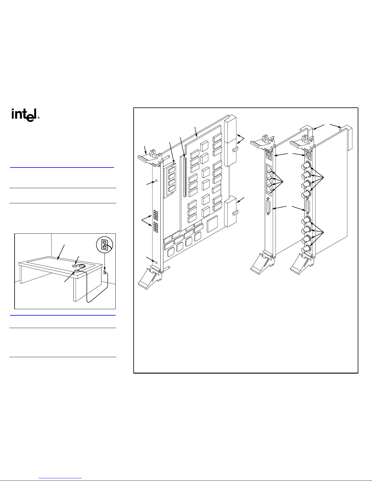
Out of Service LED—Indicates board is out of service or in
reset from host
Alarm Status LEDs:
RED—Indicates loss of clock on incoming lines from external
networks
YELLOW—Indicates loss of frame synchronization at far end
external networks
Carrier Signal—Indicates board is powered up and receiving
signal from external E–1 sources
Loopback—Indicates the E–1 networks are in loopback mode
Power LED—Indicates board is powered up
Board Extractor
Global Memory Module
J5—Signal Processor Daughterboard connector
Signal Processor Daughterboard
P1, P4, and P5—Compact PCI board connectors to backplane
BNC Connectors—Connectors to external E–1
(75-Ohm) telephone network interface
P2—Network interface test port
J1, J2, J3, and J4—Connectors to external E–1
(120-Ohm) digital telephone network interface
Ethernet Connectors*—Connects to Ethernet network
P5—Rear I/O module connector to CompactPCI
backplane
1
2
3
4
5
6
8
8
7
12
13
9
11
10
1.
2.
3.
4.
5.
6.
7.
8.
9.
10.
11.
12.
13.
Compact PCI Baseboard Rear I/O Modules
E–1 120-Ohm
E–1 75-Ohm
9
Physical Description
R
E
D
Y
E
L
R
E
D
Y
EL
C
A
R
R
S
G
N
L
L
O
O
P
B
A
C
K
C
A
R
R
S
G
N
L
L
O
O
P
B
A
C
K
O
U
T O
F
SER
VICE
PO
W
ER
C
o
m
p
a
c
tP
C
I
A
L
A
R
M
S
/
S
T
A
T
U
S
4
3
2
1
Page 2
Installing the Rear I/O Module
NOTE: If you are installing the product in a live insertion
system (powered-on), you should install the Rear I/O
module before the main board.
1. Work at a static-safe area. Turn the power to the
chassis OFF if you do not have a live insertion
system. If you have live insertion capability, the
power to the chassis can remain ON.
2. Remove the cover plate or open the chassis door.
3. If you already installed the main board, locate the
rear of the selected slot; otherwise, select an empty
peripheral expansion bus slot.
4. Install the Rear I/O module in the rear of the slot. Use
the slot’s board guides as you insert the board into
the chassis slot. Make sure that the tabs on the board
extractors engage the guide holes in the chassis card
cage, then lock down the board extractors until the
red locking tabs snap shut.
CAUTION: CompactPCI backplane pins are bent
easily. Make sure that the board is seated with hand
pressure before fully seating board. If board extractors
are used to seat the board, make sure to seat evenly.
Installing the Main Board
NOTE: If you are installing the product in a live insertion
system (with the power on), you should install the Rear I/O
module before the main board.
1. Work at a static-safe area. Turn the power to the
chassis OFF if you do not have a live insertion
system. If you have live insertion capability, the
power to the chassis can remain ON.
2. Remove the cover plate or open the front chassis
door.
3. If you already installed the Rear I/O module, locate
the front of the selected slot; otherwise, select an
empty peripheral expansion bus slot.
4. Install the Intel NetStructure main board in the front of
the selected slot. Use the slot’s board guides as you
insert the board into the chassis slot. Make sure that
the tabs on the board extractors engage the guide
holes in the chassis card cage, then lock down the
board extractors until the red locking tabs snap shut.
CAUTION: CompactPCI backplane pins are bent
easily. Make sure that the board is seated with hand
pressure before fully seating board. If board extractors
are used to seat the board, make sure to seat evenly.
NOTE: If the power to the chassis is on, power is
automatically applied to the board, the Out of Service LED
lights briefly and then goes out, and the Power LED goes
on.
5. Tighten the retaining screws to secure the board
firmly in the chassis slot (optional).
6. If the power to the chassis is turned OFF, turn the
power to the chassis ON.
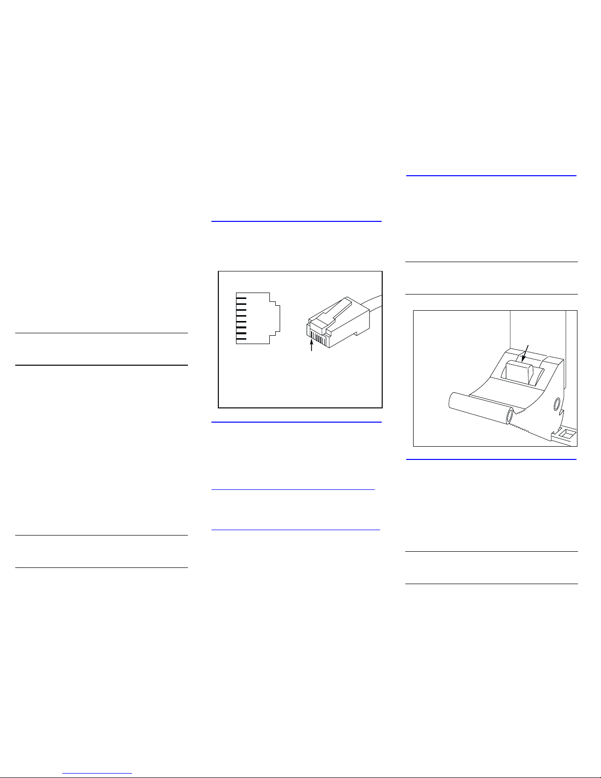
Connecting External Cables
For information about the pinouts for the network interface
cable, refer to the Pinouts for the RJ-48C figure.
Pinouts for the RJ-48C
RJ-48C Network Interface
Cable Connector
CHASSIS GROUND
CHASSIS GROUND
UNUSED
XMIT_TIP
XMIT_RING
UNUSED
RCV_TIP
RVC_RING
8
7
6
5
4
3
2
1
8
7
6
5
4
3
2
1
Pinouts for the RJ–48C
Jack on Bracket
Pin 1
After Installing the Hardware
After installing the hardware, proceed with the system
software installation as described in the system software
documentation (if applicable).
For technical specifications and product information, see
the Intel® website at
http://www.intel.com/design/network/products/telecom
Direct Return Authorization (DRA) Process
To return a board for repair or credit in the American
geographies, use the online form at
http://www.intel.com/support/motherboards/draform.htm
To return a board for repair or credit in all other
geographies, please contact your distributor.
Removing the Main Board
Exercise caution when removing the board from a
CompactPCI chassis. The board extractors are equipped
with red locking tabs that lock when the board is correctly
positioned in the chassis.
To remove the board from the chassis, simultaneously
press down both red locking tabs (see the CompactPCI
Extractor figure) on the extractors before applying
pressure away from the center of the board to disengage.
CAUTION: When removing the board, if the red locking
tabs on the extractors are not pressed while applying
pressure to the extractors, there is a risk of breaking the
tabs.
CompactPCI Extractor
Press and hold down the red
locking tabs on both board
extractors before applying
pressure to the board.
Removing the Rear I/O Module
NOTE: In a live insertion (powered-on) system, do not
remove and replace a Rear I/O module while the main
(front) board is in service. Remove the front board first,
then remove and replace the Rear I/O module, and then
reinsert the front board.
To remove the board from the chassis, simultaneously
press down both red locking tabs (see the CompactPCI
Extractor figure) on the extractors before applying
pressure away from the center of the board to disengage.
CAUTION: When removing the board, if the red locking
tabs on the extractors are not pressed while applying
pressure to the extractors, there is a risk of breaking the
tabs.
 Loading...