

Page 1

Intel® Enpirion® Power Solutions
EM22xx Evaluation Board User Guide
User Guide
© 2017 Intel Corporation. All rights reserved. Intel, the Intel logo, Altera, Enpirion, and the Enpirion logo are trademarks of Intel Corporation in the US and/or
other countries. Other marks and brands may be claimed as the property of others. Intel warrants performance of its FPGA and semiconductor products to
current specifications in accordance with Intel's standard warranty, but reserves the right to make changes to any products and services at any time without
notice. Intel assumes no responsibility or liability arising out of the application or use of any information, product, or service described herein except as
expressly agreed to in writing by Intel. Intel customers are advised to obtain the latest version of device specifications before relying on any published
information and before placing orders for products or services.
Page 2

User Guide | Intel® Enpirion® Power Solutions
EM22xx Evaluation Board User Guide
Contents
1. Description ........................................................................................................................................................................ 3
2. Required Equipment ..................................................................................................................................................... 3
3. Evaluation Board Overview ........................................................................................................................................ 4
4. Instructions ....................................................................................................................................................................... 5
5. Evaluation Board Schematic ...................................................................................................................................... 7
6. Bill of Materials ................................................................................................................................................................ 9
7. Revision History ............................................................................................................................................................ 11
List of Figures
Figure 1: EM22xx Evaluation Board Overview (View From Top - EM2260 shown as an example) ..... 4
Figure 2: Jumper Table, Marked On The EM22xx Evaluation Board Silk Screen ....................................... 6
Figure 3: Evaluation Board Schematic – Power ......................................................................................................... 7
Figure 4: Evaluation Board Schematic – AUX ............................................................................................................. 8
List of Tables
Table 1: Required Equipment ........................................................................................................................................... 3
Table 2: Bill of Materials...................................................................................................................................................... 9
2
Page 3
User Guide | Intel® Enpirion® Power Solutions
EM22xx Evaluation Board User Guide
1. Description
The EM22xx family are PowerSoC synchronous Dual Phase buck converters from the Intel®
Enpirion® Power Solutions family. The EM22xx series feature an advanced controller, gate
drivers, synchronous MOSFET switches, and high performance inductors. Only input and
output filter capacitors and a few small signal components are required for a complete
solution.
Differential remote sensing and ±0.5% set-point accuracy provide precise regulation over
line, load and temperature variation. Very low ripple further reduces accuracy uncertainty to
provide best in class static regulation for today’s FPGAs, ASICs, processors, and DDR
memory devices.
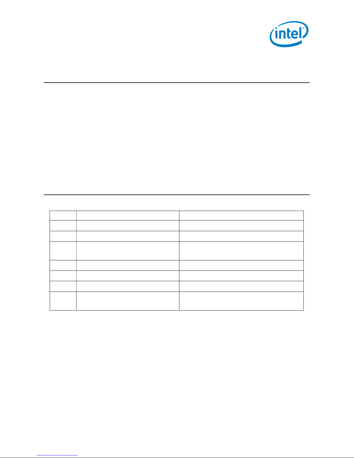
2. Required Equipment
Table 1: Required Equipment
Item # Equipment Recommended
1 DC Power Supply 20V/30A, adjustable
2 Electronic Load 50…100A with dynamic load capabilities
3 Intel Enpirion PMBus
Communication Interface Dongle
4 Intel 25A Mini Slammer Loads Fits the on-board LD1, LD2 & LD3 socket
5 DMM 6 ½ digit
6 Oscilloscope 4 channels, 0.5 GHz BW
7 Cables >60A capability, eyelet terminal, 4 mm
diameter hole, 10 mm outer diameter
3
Page 4
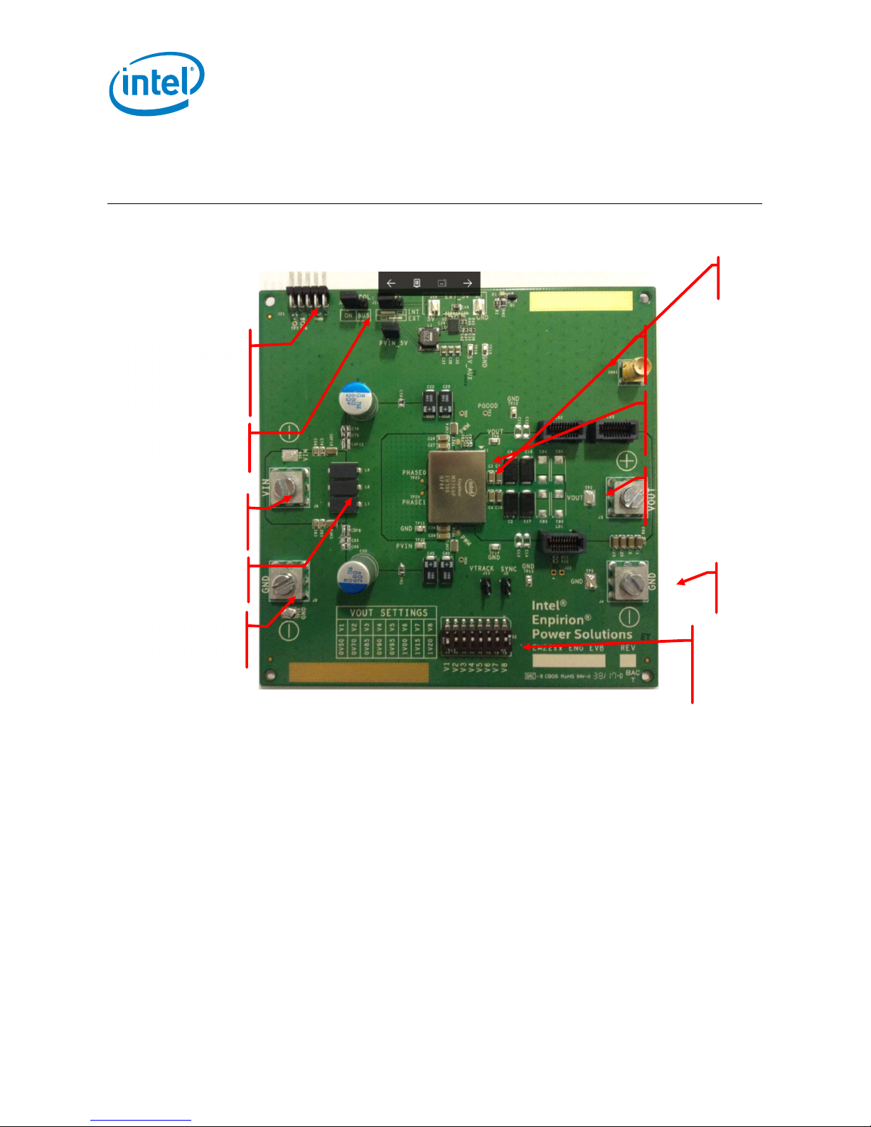
3. Evaluation Board Overview
VOLTAGE
GROUND
User Guide | Intel® Enpirion® Power Solutions
EM22xx Evaluation Board User Guide
EM2260
PMBus
Communication
Interface Dongle
ENABLE
INPUT
Ferrite Beads
INPUT
OUTPUT
MONITOR
OUTPUT
DECOUPLING
OUTPUT
VOLTAGE
OUTPUT
VOLTAGE
SELECTOR
Figure 1: EM22xx Evaluation Board Overview (View From Top - EM2260 shown as an example)
OUTPUT
4
Page 5

User Guide | Intel® Enpirion® Power Solutions
CAUTION:
Incorrect
polarity of the power supply may cause permanent
EM22xx Evaluation Board User Guide
4. Instructions
1) Connect the power supply
Set the Power Supply to 12V/10A.
Connect the power supply to the board (make sure that the power supply is OFF)
with two patch cables, not longer than 6 inches (15 cm). Using longer wires is possible,
provided that additional bulk is added to the board and the input voltage is
monitored at the board level. For lower Input voltages e.g. 5V further bulk
capacitance maybe required depending on the Power Supply being used. Please use
INPUT GROUND and INPUT VOLTAGE eyelet-terminated cables to connect the
power.
Please observe the correct polarity.
board damage!
CAUTION: Power supply voltage above 20V may cause permanent board
damage!
2) Connect the load
Connect the load to the OUTPUT GROUND and OUTPUT voltage with patch cables,
no longer than 6 inches (15 cm).
Please observe the correct polarity.
3) Check jumper settings
The board will arrive with one jumper on the J6 (enabling the Output through pulling
the CTRL pin high), one jumper on J14 (INT – this connects the on-board 5VCC supply)
and one jumper on J15 (PVIN_5V – this biases the 5V on board DC-DC converter). If
an auxiliary 5V power supply is needed (connected between J16 (+) and J17 (-)), J14
should be placed across the “EXT” position while J15 can be removed. If operating
PVIN at 6V or lower an external 5V supply is required to ensure correct operation.
(For PVIN values below 6V the on-board switcher cannot guarantee a 5Vout output)
4) Connect the PMBUS GUI interface dongle
The USB Dongle can be inserted only in the correct position, with pin one towards
GND. All pins must be properly inserted.
Prerequisite: the latest GUI software must be installed on a Windows PC.
5
Page 6

User Guide | Intel® Enpirion® Power Solutions
EM22xx Evaluation Board User Guide
5) Set the output voltage
Using the chart from the silkscreen, please select the desired output voltage, using
ONLY ONE switch ON. This setting will be read by the module when the part is
powered on; changing the resistor on the fly will not have any effect.
6) Power-up the board
After all preparations above, the board should be ready to perform.
The voltage range is marked on the board, as shown in Figure 2:
Vout Settings
0V50 V1
0V70 V2
0V85 V3
0V90 V4
0V95 V5
1V00 V6
1V15 V7
1V20 V8
Figure 2: Jumper Table, Marked On The EM22xx Evaluation Board Silk Screen
For instruction on how to use the EM22xx GUI, please read “GUI User Guide.”
NOTE: To measure the Bode Plot of the DC-DC converter, J12 must be populated which is then used to connect the
probes of the phase analyzer.
6
Page 7

User Guide | Intel® Enpirion® Power Solutions
EM22xx Evaluation Board User Guide
5. Evaluation Board Schematic
J3
J4
567
VDD3V3
2N7002K
2
123
R63
V_OUT
171819
1516
1314
1112
910
78
56
C4
C3
C10
C9
C50
C51
C52
110
111
112
113
114
115
116
117
118
119
120
121
122
123
124
125
126
127
128
129
130
131
132
133
134
135
136
137
138
139
140
141
142
143
144
145
146
147
148
149
150
151
152
R3
1K00
CTRL
567
8
4
8
GND
123
J22
DNI
1
C5
100u
470R
C1
100u
20
LD1
132
4
100u
100u
100u
100u
DNI
DNI
DNI
C8
470u
+
C2
+
470u
C7
470u
+
470uF/2.5V/3mOhm
C6
+
470u
107
108
109
VOUT_110
VOUT_111
VOUT_112
VOUT_113
VOUT_108
VOUT_109
VOUT_114
VOUT_115
VOUT_116
VOUT_117
VOUT_118
VOUT_119
VOUT_120
VOUT_121
VOUT_122
VOUT_123
VOUT_124
VOUT_125
VOUT_126
VOUT_127
VOUT_128
VOUT_129
VOUT_130
VOUT_131
VOUT_132
VOUT_133
VOUT_134
VOUT_135
VOUT_136
VOUT_137
VOUT_138
VOUT_139
VOUT_140
VOUT_141
VOUT_142
VOUT_143
VOUT_144
VOUT_145
VOUT_146
VOUT_147
VOUT_148
VOUT_149
VOUT_150
VOUT_151
VOUT_152
VOUT_11VOUT_22VOUT_33VOUT_44PG6CTRL7SALRT8VDD3395VCC10SDA11SCL12DISABLE013NC1414PWM015NC1616NC1717NC1818PVIN_1919PVIN_2020PVIN_2121PVIN_2222PVIN_2323PVIN_2424NC2525PGND_2626PGND-2727PGND_2828PGND_2929PGND_3030PGND_3131PGND_32
R5
10K0
CONTROL
123
J6
2
100R
R12
0R0
R11
C20
100u
C15
100u
C14
DNI
C13
DNI
C12
DNI
C11
DNI
C53
DNI
+
C19
470u
+
C18
470u
+
C17
470u
+
C16
470u
SYNC
RTUNE
RVSET
TP23
TP26
ADDR1
ADDR0
VTRACK
VSENN
VSENP
93
94
95
96
97
98
99
100
101
102
103
104
105
106
NC95
RSET
SENP
SENN
SYNC
VOUT_105
VOUT_106
VOUT_107
VOUT_5
5
CTRL
PWM1
TRACK
ADDR0
ADDR1
RTUNE
DISABLE1
S1
TP22
TP27
C21
2u2/10V
FB1
742792780
5V
C43
DNI
VDD3V3
SCL
SDA
SALERT
171819
V_OUT
1516
1314
1112
910
78
56
171819
V_OUT
1516
1314
1112
910
78
56
91
NC9292NC93
EM22xxQI
Control Loop Injection
TP5
20
LD3
132
4
20
LD2
132
4
C47
DNI
C46
DNI
22u
C27
PVIN
22u
C26
83
85
84
NC85
PVIN_8686PVIN_8787PVIN_8888PVIN_8989PVIN_9090PVIN_91
PGND_84
32
CHF5
CHF4
C29
22u
TP32
PVIN
47 0nF/ 25V LI CC
22u
C28
C60
DNI
C49
DNI
+
C40
100u
+
C45
100u
+
C25
DNI
+
C24
DNI
TP11
C23
+
100u
C22
+
100u
C55
680u
+
C54
680u
+
TP15
TP14
PGND
TP13
TP12
J2
1
2
SYNC
SYNC
PGND_76
PGND_75
PGND_74
PGND_73
PGND_7777PGND_7878PGND_7979PGND_8080PGND_8181PGND_8282PGND_83
PGND_72
PGND_71
PGND_70
PGND_69
PGND_68
PGND_67
PGND_66
PGND_65
PGND_64
PGND_63
PGND_62
PGND_61
PGND_60
PGND_59
PGND_58
PGND_57
PHASE1
NC55
PHASE0
PGND_53
PGND_52
PGND_51
PGND_50
PGND_49
PGND_48
PGND_47
PGND_46
PGND_45
PGND_44
PGND_43
PGND_42
PGND_41
PGND_40
PGND_39
PGND_38
PGND_37
PGND_36
PGND_35
PGND_34
PGND_33
33
SMA1
4
R64
DNI
TP2
CHF2
CHF1
470nF/25V LICC
TP4
C90
DNI
+
+
C89
DNI
DNI
+
C88
DNI
+
C87
C86
DNI
+
C85
+
DNI
C84
DNI
+
C83
DNI
+
125mm*125mm, 8Layers, 2oz Copper for all Layers
PGOOD
PG
TP3
R62
10K0
VDD3V3
5V
R1
1K00
1
Q1
A1K
3
2
D1
R6
DNI
R7
SYNC
76
75
74
73
72
71
70
69
68
67
66
65
64
63
62
61
60
59
58
57
56
55
54
53
52
51
50
49
48
47
46
45
44
43
42
41
40
39
38
37
36
35
34
DNI
ADDR1
ADDR0
ADDR0
ADDR1
RVSET
TP24
TP25
C68
C67
C66
C65
PVIN
X2
X3
X1
RVSET
S2
1
2
3
4
5
6
7
8
C93
DNI
+
C92
DNI
+
DNI
C56
+
C57
+
DNI
CHF9
CHF8
47 0nF/ 25V LI CC
X4
MTHn_320m334
1k
R35
R34
V8
V7
R33
V6
16
15
R32
V5
14
13
V4
12
R31
11
10
V3
9
R30
V2
V1
R29
R28
C82
C81
C80
C79
C78
C77
C76
C75
CHF13
47 0nF/ 25V LI CC
CHF12
1.2V
1k5
1.15V
3k24
1.0V
4k22
0.95V
5k36
0.9V
7k68
0.85V
14k3
0.7V
23K2
0.5V
R20
392R
RTUNE
RTUNE
L8
28F0181-1SR-10
L9
28F0181-1SR-10
L10
28F0181-1SR-10
123
J8
8
28F0181-1SR-10
L11
28F0181-1SR-10
L12
28F0181-1SR-10
VTRACK
DNI
C64
C72
100nF(COG)
C71
C63
C70
C62
C61
C69
CHF11
CHF7
47 0nF/ 25V LI CC
CHF10
CHF6
TP10
123
J9
4
8
567
567
R23
100nF(COG)
R24 1K00/0.1%
VTRACK1
1
2
47 0nF/ 25V LI CC
J13
4
TRACK
GND
L7
TP9
VIN
Figure 3: Evaluation Board Schematic – Power
7
Page 8

C33
Ext_5V
PM Bus Components
100p
R38
90K9
R37
10K0
FSW5V
CMP5V
12
11FB10
FSW
SS1SYNC2BOOT3PVIN4SW5PGND
U2
ER3105QI
SS5V
Tss =
1.41m s
User Guide | Intel® Enpirion® Power Solutions
EM22xx Evaluation Board User Guide
5V
123
J14
5VSEL
R45
12K4
R40
AVINO
FB5V
POK5V
9
8EN7
POK
COMP
EPAD
AVINO
6
BST5V
SW5V
PVIN5V
4n7
C38
C34 100n
C39
100K
13
470p
C42
1u
R43
133K
R42
3K32
EN5V
Fsw=70 0kHz
R41 10K0
C41
10u
R4
DNI
R2
DNI
PGOOD
TP7
TP6
R61
DNI
C91
100nf
8
10
10
9
2244668
J21
11335
779
5
VDD3V3
L1 22 uH
NR6028T220M
5V Bias Supply
500mA
5V
C37
47u
C36
47u
5V0_AUX
C35
TP19
47u
PVIN_5V
PVIN
5V_EXT
2
1
J15
C44
10u
J16
J17
GND
Figure 4: Evaluation Board Schematic – AUX
GND
8
Page 9

User Guide | Intel® Enpirion® Power Solutions
EM22xx Evaluation Board User Guide
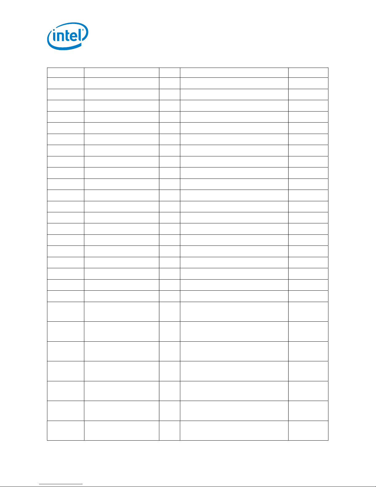
6. Bill of Materials
Table 2: Bill of Materials
Type Description Qty. BOM Ref Des Mfr. Name
Capacitor 100µF 6V3 10% X5R
1206
Capacitor 470µF 2.5V 3 mΩ 8 C2,C6,C7,C8,C16,C17,C18,C19 Panasonic
Capacitor 2.2µF 16V 10% X6S
0402
Capacitor 100µF, 20V, ESR=55
mΩ
Capacitor 22µF 25V 10% X5R
1206
Capacitor 100pF 50V 5% NP0
0402
Capacitor 100nF X7R 0402 10V
10%
Capacitor 47µF 6.3V X5R 0805 3 C35,C36,C37 Taiyo
Capacitor 4.7nF X7R 0402 25V
10%
Capacitor 470pF 25V X7R 10%
0402
8 C1,C3,C4,C5,C9,C10,C15,C20 Kemet
1 C21 TDK
4 C22 C23 C40 C45 Panasonic
4 C26,C27,C28,C29 Murata
1 C33 Taiyo
Yuden
1 C34 Murata
Yuden
1 C38 Murata
1 C39 Vishay
Capacitor 10µF 25V X5R 0805
10%
Capacitor 1µF 25V 20% X5R 0402 1 C42 Taiyo
Capacitor 470nF 25V 20% X7R
0612
Capacitor 680UF 20% 20V T/H 2 C54,C55 Chemi-com
Capacitor 100nF X7R 0805 25V 20 C61,C62,C63,C64,C65,C66,C67,C68
Resistor 1k 1% 0805 1 R1 Panasonic
Resistor 1k 1% 0402 1 R3 Panasonic
9
2 C41,C44
Yuden
12 CHF1,CHF2,CHF4,CHF5,
CHF6,CHF7,CHF8,CHF9,
CHF10,CHF11,CHF12,CHF13
C69,C70,C71,C72, C75,C76,C77
C78,C79,C80,C81,C82
Murata
Murata
Page 10
User Guide | Intel® Enpirion® Power Solutions
EM22xx Evaluation Board User Guide
Type Description Qty. BOM Ref Des Mfr. Name
Resistor RES 10k OHM 1% 0402
Resistor 0 OHM 5% 0402 1 R11 Panasonic
Resistor 100R OHM 1% 0402 1 R12 Panasonic
Resistor 392 OHM 0.1% 0603 1 R20 Panasonic
Resistor 1K OHM 0.1% 0402 1 R24 Panasonic
Resistor 23.2K OHM 1% 0402 1 R28 Panasonic
Resistor 14.3K 0603 1%, 1 R29 Panasonic
Resistor 7.68K OHM 1% 0603 1 R30 Panasonic
Resistor 5.36K OHM 1% 0603 1 R31 Panasonic
Resistor 4.22K OHM 1% 0603 1 R32 Panasonic
Resistor 3.24K OHM 0603 1% 1 R33 Panasonic
Resistor 1K5 OHM 0603 1% 1 R34 Panasonic
Resistor 1K OHM 1% 0603 1 R35 Panasonic
Resistor 90.9K OHM 1% 0402 1 R38 Yageo
Resistor 100K OHM 1% 0402 1 R40 Panasonic
Resistor 3.32K OHM 1% 0402 1 R42 Panasonic
3 R5,R37,R41 Panasonic
Resistor 133K OHM 1% 0402 1 R43 Panasonic
Resistor 12.4K OHM 1% 0402 1 R45 Panasonic
Resistor 10K OHM 1% 0805 1 R62 Panasonic
Resistor 470R OHM 5% 0603 1 R63 Panasonic
LED LED GREEN CLEAR
0603
Inductor INDUCTOR, 22UH, 1.3A, 1 L1 Taiyo
Inductor Ferrite Bead, 115 ohm,
10 A, 1000 µohm
MOSFET MOSFET N-CH 60V
300MA SOT23
Inductor FERRITE BEAD 220
OHM 0402
Connector
IC ER3105DI Wide VIN
INTEL 25A SLAMER
LOAD CONNECTOR
500mA Synch Buck Reg
1 D1 LITE-ON
INC
Yuden
6 L7,L8,L9,L10,L11,L12 Laird Tech
1 Q1 Fairchild
1 FB1 Wurth
3 LD1, LD2, LD3 Samtec
1 U2 Intel
Enpirion
10
Page 11

7. Revision History
Revision
Description Revision Date
Number
001 Initial release. December 2017
002 Minor updates relating to RVSET resistor values March 2018
© 2017 Intel Corporation. All rights reserved. Intel, the Intel logo, Altera, Enpirion, and the Enpirion logo are trademarks of Intel Corporation in the US and/or
other countries. Other marks and brands may be claimed as the property of others. Intel warrants performance of its FPGA and semiconductor products to
current specifications in accordance with Intel's standard warranty, but reserves the right to make changes to any products and services at any time without
notice. Intel assumes no responsibility or liability arising out of the application or use of any information, product, or service described herein except as
expressly agreed to in writing by Intel. Intel customers are advised to obtain the latest version of device specifications before relying on any published
information and before placing orders for products or services.
 Loading...