

Page 1

Intel® Atom™ Processor E660 with
®
Intel
Platform Controller Hub
EG20T Development Kit
User Manual
January 2012
Document Number: 324213-002
Page 2

Legal Lines and Disclaim er s
INFORMATION IN THIS DOCUMENT IS PROVIDED IN CONNECTION WITH INTEL PRODUCTS. NO LICENSE, EXPRESS OR IMPLIED, BY ESTOPPEL OR
OTHERWISE, TO ANY INTELLECTUAL PROPERTY RIGHTS IS GRANTED BY THIS DOCUMENT. EXCEPT AS PROVIDED IN INTEL'S TERMS AND CONDITIONS
OF SALE FOR SUCH PRODUCTS, INTEL ASSUMES NO LIABILITY WHATSOEVER AND INTEL DISCLAIMS ANY EXPRESS OR IMPLIED WARRANTY , RELATING
TO SALE AND/OR USE OF INTEL PRODUCTS INCLUDING LIABILITY OR WARRANTIES RELATING TO FITNESS FOR A PARTICULAR PURPOSE,
MERCHANTABILITY, OR INFRINGEMENT OF ANY PATENT, COPYRIGHT OR OTHER INTELLECTUAL PROPER TY RIGHT.
A "Mission Critical Application" is any application in which failure of the Intel Product could result, directly or indirectly, in personal injury or death.
SHOULD YOU PURCHASE OR USE INTEL'S PRODUCTS FOR ANY SUCH MISSION CRITICAL APPLICATION, YOU SHALL INDEMNIFY AND HOLD INTEL AND
ITS SUBSIDIARIES, SUBCONTRACTORS AND AFFILIATES, AND THE DIRECTORS, OFFICERS, AND EMPLOYEES OF EACH, HARMLESS AGAINST ALL
CLAIMS COSTS, DAMAGES, AND EXPENSES AND REASONABLE ATTORNEYS' FEES ARISING OUT OF , DIRECTL Y OR INDIRECTL Y, ANY CLAIM OF PRODUCT
LIABILITY, PERSONAL INJURY, OR DEATH ARISING IN ANY WAY OUT OF SUCH MISSION CRITICAL APPLICATION, WHETHER OR NOT INTEL OR ITS
SUBCONTRACTOR WAS NEGLIGENT IN THE DESIGN, MANUFACTURE, OR WARNING OF THE INTEL PRODUCT OR ANY OF ITS PARTS.
Intel may mak e ch anges t o s pecifi catio ns and pr odu ct desc ripti ons at a ny t ime , wit hout notice. Desi gner s mu st no t rely on the absence or characteristics
of any features or instructions mar ke d "reserved" or "undefined". Intel reserve s thes e for fut ur e definition and shall have no responsibility whatsoever
for conflicts or incompatibilities arising from future changes to them. The information here is subject to change without notice. Do not finalize a design
with this information.
The products described in this document may contain design defects or errors known as errata which may cause the product to deviate from published
specifications. Current characterized errata are available on request.
Contact your local Intel sales office or your distributor to obtain the latest specifications and before placing your product order.
Copies of documents which ha v e a n ord er numb er and are r efer enced in this document, or other In tel literature, may be obtained by calling 1-800-548-
4725, or go to:
http://www.intel.com/#/en_US_01.
Intel processor numbers are not a measure of performanc e. P roc esso r num b er s differ entiate features within each processor fami ly, not across different
processor families. Go to: http://www.intel.com/products/processor%5Fnumber/ for detail s .
Also, they are notα Intel® Hyper-Threading Technology requires a computer system with a processor supporting Intel® HT T echnology and an Intel® HT
Technology-enabled chipset, BIOS and operating system. Performance will vary depending on the specific hardware and software you use. For more
information including details on which processors support Intel
β Intel® High Definition Audio requires a system with an appropriate Intel® chipset and a motherboard with an appropriate CODEC and the necessary
drivers installed. System sound quality will vary depending on actual implementation, controller, CODEC, drivers and speakers. For more information
about Intel® HD audio, refer to http://www.intel.com/.
χ 64-bit computing on In tel® architecture requires a computer system with a processor , chipset, BIOS, operating system, device drivers and applications
enabled for Intel® 64 architecture. Per forma nce will v ary depe nding on y our hard ware a nd so ftwar e config ur ati ons. Consu lt wit h you r system v endo r for
more information.
δ Intel® Virtualization Technology requires a computer system with an enabled Intel® processor, BIOS, virtual machine monit or (VMM) and, for some
uses, certain computer system software enabled for it. Functionality, performance or other benefits will vary depending on hardware and software
configurations and may require a BIOS update. Software applications may not be compatible with all operating systems. Please check with your
application vend or.
ε The original eq u ip men t manufacturer must provide Intel® T ru ste d P la tf or m Mo du le ( In te l® TPM) functionality, which requires an Intel® TPM-supported
BIOS. Intel® TPM functionality must be initialized and may not be available in all countries.
®
HT Technology, see http://www.intel.com/products/ht/hyperthreading_more.htm.
θ For Enhanced Intel SpeedSte p® Technology, see the Processor Spec Finder or contact your Intel representative for more information.
I2C* is a two-wire communications bus/protocol developed by Philips. SMBus is a subset of the I2C* bus/protocol and was developed by Intel.
Implementations of the I2C* bus/protocol may require licenses from various entities, including Philips Electronics N.V. and North American Philips
Corporation.
BunnyPeople, Cele ron, Celeron I nside, Centr ino, Centr ino Inside, Core Inside, i960 , Intel, the In tel logo, Inte l AppUp, Intel A tom, Intel Atom Inside, Intel
Core, Intel Inside, the Intel Ins ide log o, Intel NetBurst, Intel NetM erge, I nte l NetS t ru c tur e, Intel S ing l eDr iver, Intel SpeedStep, Intel Sponsors of
T om or r ow., the Intel Sponsors of Tomorrow. logo, Intel S trataFlash, Intel Viiv, Intel vPro, Intel XSca l e, I nTru, the InTr u logo, InTru soundmark, Itanium,
Itanium Inside, MCS, MMX, Moblin, Pentium, Pentium Inside, skoool, the skoool logo, Sound Mark, The Journey Inside, vPro Inside, VTune, Xeon, and
Xeon Inside are trademarks of Intel Corporation in the U.S. and other countries.
*Other names and brands may be claimed as the property of others.
Copyright © 2009, 2012, Intel Corporation . All rig hts reserv ed.
Intel® Atom™ Processor E660 with Intel® Platform Controller Hub EG20T Development Kit
User Manual January 2012
2 Document Number: 324213-002
Page 3

Contents
Contents
1.0 Introduction..............................................................................................................7
1.1 About the Development Kit...................................................................................7
1.2 Terminology .......................................................................................................8
1.3 Technical Support. ................................................. ............................................ 10
1.3.1 Additional Technical Support..................... ............................................... 10
1.4 Product Literature ............................................................................................. 10
1.5 Reference Documents ........................................................ ................................ 11
2.0 Getting St arted........................................................................................................13
2.1 Overview ......................................................................................................... 14
2.2 Major Features........................ ................................................. ......................... 15
2.3 Processor Support ............................................................................................. 17
2.3.1 Processor Voltage Regulators ................................................................... 17
2.4 COM Express* Module Support.......... ... .................................................. ............. 17
2.5 Subsystem Descriptions ..................................................................................... 17
2.5.1 Intel
2.5.2 COM Express* Connector ............................................... ......................... 17
2.5.3 Intel
2.5.4 System Memory..................................................... .......................... ...... 18
2.5.5 Display .................................................................................................19
2.5.6 PCI Express* Slots/ PCI* Slots................................................................. 19
2.5.7 SATA Connectors.................................................................................... 20
2.5.8 USB Connectors .............................. ................................................. ...... 21
2.5.9 Gigabit Ethernet Connector...................................................................... 22
2.5.10 SD/SDIO/MMC....................................................................................... 22
2.5.11 UART.................................................................................................... 23
2.5.12 I
2.5.13 SPI.......................................................................................................26
2.5.14 CAN ..................................................................................................... 26
2.5.15 Serial ROM ............................................................................................ 26
2.5.16 LPC Bus ................................................................................................ 27
2.5.17 Intel
2.5.18 Clocks .................................................................................................. 27
2.5.19 Real Time Clock ..................................................................................... 29
2.5.20 In-Target Probe (ITP) and Debug Support.................................................. 29
2.5.21 Power Supply Solution .......... .......................... ........................................ 30
2.5.22 Board Size........... .... .................................................. ............................ 30
3.0 Power Management ................................................................................................. 31
3.1 Power Measurement Support ............ .......................... ........................................ 31
4.0 Reference Boar d S u mmary ...................................................................................... 35
4.1 Intel
®
Development Kit Features ....................... .................................................. ......... 35
4.2 Connectors....................................................................................................... 36
4.3 Configuration Settings ....................................................................................... 38
4.3.1 Configuration Jumpers/Switches............................................................... 38
4.3.2 BSEL Jumper Settings.............................. ............................................... 43
4.3.3 Manual VID Support for CPU ..... ............................................................... 44
4.4 Power On and Reset Push Buttons ....................................................................... 46
®
Atom™ Processor E660..................................................................17
®
Platform Controller Hub EG20T .......................................................18
2
C* ..................................................................................................... 25
2.5.16.1 Super IO (SIO).............. .... ................................................. ...... 27
2.5.16.2 POST Code Display CPLD ........................................................... 27
2.5.16.3 Intel
®
High Definition Audiob (Intel® HD Audiob)........................................ 27
®
Trusted Platform Modulee (Intel® TPMe) Header ................ .. 27
Atom™ Processo r E660 with Intel® Platform Controller Hub EG20T
January 2012 User Manual
Document Number: 324213-002 3
Intel® Atom™ Processor E660 with Intel® Platform Controller Hub EG20T Development Kit
Page 4

Contents
4.5 LEDs................................................................................................................46
4.6 PCI Express* Routing .........................................................................................48
4.6.1 PCI Express* x1 Port0.............................................................................48
4.6.2 PCI Express* x1 Port1.............................................................................48
4.6.3 PCI Express* x1 Port2.............................................................................48
4.6.4 PCI Express* x1 Port3.............................................................................49
4.7 JTAG Headers....................................................................................................49
5.0 Software ..................................................................................................................51
5.1 Overview of Software Availability for the Development Kit.......................................51
5.2 Platform Drivers for the Development Kit ..............................................................52
5.3 EFI Firmware ....................................................................................................52
5.3.1 EFI Firmware Features.............................................................................52
5.3.2 Where to Download.................................................................................53
5.3.3 BIOS/EFI Firmware Update Tool................................................................53
5.3.4 EFI Firmware/BIOS Status Code ...............................................................53
5.3.5 Links to Vendors Pr oviding a BIOS Solutio n for the Intel
®
Atom™
Processor E660.......................................................................................54
5.4 WinCE BSP Vendors ...........................................................................................54
5.5 Intel
®
Embedded and Media Graphic Driver...........................................................54
5.6 Virtual Machine Monitor Software (VMM Software)..................................................54
5.7 CPLD Firmware Update.......................................................................................55
5.7.1 CPLD Firmware Update on the COM Express* Module ..................................55
5.7.2 CPLD Firmware Update on the Carrier Board...............................................55
5.8 Software Included in the Development Kit.............................................................55
5.9 Operating System Installation .................... ........................... ..............................56
5.9.1 Windows* XP SP3.................................................................... ............... 5 6
5.9.2 MeeGo*.................................................................................................59
5.9.3 Timesys Fedora* Remix...........................................................................59
6.0 Quick Start...............................................................................................................60
6.1 Required Peripherals ..........................................................................................60
6.2 Display Assembly (LVDS Panel) ...........................................................................61
6.3 Heat Sink Installation.........................................................................................64
6.3.1 COM Express* Module and Carrier Board....................................................64
6.3.2 Heat Sink Installation..............................................................................65
6.4 Power On..........................................................................................................66
6.4.1 Power Up...............................................................................................66
6.4.2 Power Down...........................................................................................67
Figures
1Intel® Atom™ Processo r E660 with Intel® Platform Controller Hub EG20T
Development Kit ................... ... .................................................. ..............................13
2 Block Diagram .........................................................................................................14
3 PCI Express* Block Diagram of the Carrier Board..........................................................20
4 SATA Block Diagram in the Carrier Board.....................................................................21
5 USB-Host Block Diagram in the Carrier Board...............................................................22
6 UART Block Diagram in the Carrier Board.....................................................................24
7Intel
8 Clock Circuit Diagram in the Carrier Board .................................................... ...............28
9 Clock Changing Circuit Diagram for the Intel
10 COM Express* Module Components (Top View).............................................................35
11 Carrier Board Feature Placement ................................................................................36
®
Atom™ Processor E660 with Intel® Platform Controller Hub EG20T Development Kit
Intel
User Manual January 2012
4 Document Number: 324213-002
®
Platform Controller Hub EG20T UART Port0 Connection Diagram in the
Carrier Board.................... .... ................................................. ........................... .......25
®
Platform Controller Hub EG20T in
the Carrier Board...................................... ................................................. ............... 2 9
Page 5

Contents
12 Carrier Board Connectors .......................................................................................... 37
13 COM Express* Module Configuration Jumpers/Switches................................................. 39
14 Carrier Board Configuration Jumpers/Switches............................................................. 40
15 Carrier Board LEDs................................................................................................... 47
16 JTAG Chain on the COM Express* Module.................................................................... 49
17 Installing the Intel
®
PCH EG20T SATA Driver - press F6 ............ .................................... 56
18 Selecting the SCSI Adapter ....................................................................................... 57
19 USB Host Controller #1 Port Connection...................................................................... 58
20 AUO 8.4 inch Panel ........................ ................................................. ......................... 61
21 LVDS Cable Connected to the Carrier Board................................................................. 62
22 LVDS Connector and Cable........................................................................... ............. 63
23 COM Express* Module and Carrier Board..................................................................... 64
24 Heat Sink Components ............................................................................................. 65
25 Back Side of the Heat Sink ........................................................................................ 65
26 Sequence to Fasten the Screws.................................................. ................................ 66
Tables
1 Conventions and Terminology......................................................................................8
2 Component Names.............. ................................................. .................................... 10
3 Intel Literature Centers............................................................................................. 10
4 Reference Documents............................................................................................... 11
5 Development Kit Feature Set Summary....................................................................... 15
6 COM Express* Interface Implemented Signals ............................................................. 17
7 Supported LVDS Displays..........................................................................................19
8 Power Measurement Resistors ................................................................................... 31
9 Digital Multi-Meter Comparison ..................................................................................32
10 Carrier Board Voltage Rails........................................................................................ 32
11 Carrier Board Connectors .......................................................................................... 38
12 Configuration Jumpers/Switches Setting on the COM Express* Module ............................ 40
13 Configuration Jumper Settin gs on Carrier Board ........................................................... 41
14 Configuration Switch Settings on Carrier Board ............................................................ 43
15 BSEL Jumper Settings...............................................................................................44
16 VID vs. V
CC-CORE
17 Carrier Board LEDs................................................................................................... 48
18 JTAG Chain Jumper Options on the COM Express* Module ............................................. 49
19 Software Availability Overview................................................................................... 51
20 Platform Drivers for the Intel
Controller Hub EG20T Development Kit ....................................................................... 52
Voltage .......................................................................................... 45
®
Atom™ Processor E660 with Intel® Platform
January 2012 User Manual
Document Number: 324213-002 5
Intel® Atom™ Processor E660 with Intel® Platform Controller Hub EG20T Development Kit
Page 6

Revision History
Revision Description Revision Date
002
001 First release of development kit. October 2010
Updated Windows* XP OS installation ins tr uct ions a nd rem oved outda te d
installation instructions for other OS. Updated description of included
panel display.
§ §
January 2012
Revision History
®
Atom™ Processor E660 with Intel® Platform Controller Hub EG20T Development Kit
Intel
User Manual January 2012
6 Document Number: 324213-002
Page 7

Introduction
1.0 Introduction
This manual describes the typical hardware set-up procedures, features, and usage of
the Intel® Atom™ Processor E660 with Inte l® Platform Controller Hub EG20T
Development K it. T his do cument is writ ten f or ev alu ation by OEM s, sy stem in tegr ator s,
and embedded system developers. The document defines all jumpers, headers, LED
functions, and th eir locations on th e development platform along with subsystem
features. The document assumes basic familiarity in the fundamental concepts involved
with installing and configuring hardware for a personal computer system.
Note: Read this document in its entirety prior to applying power to the reference platform.
Intel recommends hav ing the sch ematic file s and develop ment kit boards pre sent whi le
reading this document. The references in this document correlate to reference
designators and board properti es of the Int el
Platform Controller Hub EG20T Development Kit.
®
Atom™ Processor E660 with Inte l®
Chapter 6.0 provides quick start procedures .
1.1 About the Development Kit
The development kit includes the following:
®
• COM Express* Module with Intel
down memory, system management CPLD and SPI Flash.
• Carrier board with the Intel
components and peripher al connectors for PCIe*, PCI, SD VO, SATA, USB, LAN,
LVDS, SD/SDIO/MMC, UART and audio interfaces.
• Timesys Fedora* Remix Linux operating system (pre-ins talled on the hard dr ive
included in the kit)
• Software CD with user’s guide, reference design materials, drivers and utilities
•SATA Gen2 hard drive
• USB floppy drive
•Power supply
• LVDS cable
The kit contents may be prepared with additional equipment (depending on options
made avai la ble to you at the tim e of purchase):
• LVDS panel
• VGA SDVO ADD2N card and display (instead of the LVDS display and LVDS cable)
•DVD-ROM drive
• Keyboard and mouse with PS/2 or USB interface (BIOS setting dependent)
• Ch assis with ATX power supply (or AC adapter)
Atom™ Processor E660 , 1GB DDR 2 soldered
®
Platform Controller Hub EG20T and other system
January 2012 User Manual
Document Number: 324213-002 7
Intel® Atom™ Processor E660 with Intel® Platform Controller Hub EG20T Development Kit
Page 8

1.2 Terminology
Table 1. Conventions and Terminology (Sheet 1 of 2)
Term Definition
AC Audio Codec
ACPI Advanced Configuration Power Interface
ADD2 Advanced Digital Display 2 card
ADD2-N Advanced Digital Display 2 card with PCIe* graphics lane in normal orientation
ANV Analog Validation
ATA Advanced Technology Attachment
BGA Ball Grid Array
BIOS Basic Input / Output Syste m
CAN Controller Area Network
CRB Customer Reference Board
CTS Clear To Send
DCD Data Carrier Detect
DCE Data Circuit-Terminating Equipment
DMA Direct Memory Access
DFM Design For Manufacturing
DSR Data Set Ready
DTE Data Terminal Equipment
DTR Data Terminal R eady
DVI Digital Video Interface
EBL Extended Battery Life
EFI Extensible Firmware Interface
EBL Extended Battery Life
EHCI Enhanced Host Controller Interface
EM Electromagnetic
EMI Electromagnetic Interface
ESR Equivalent Series Resi s tance
EV Electrical Validation
FAE Field Application Engineer
FWH Firmware Hub
GbE Gigabit Ethernet
GE General Embedded
GMAC Gigabit Ethernet Media Acce ss Controller
GND Ground (Signal Ground)
GPIO General Purpose Input Output
®
Intel
Audio
HD
β
Intel® High Definition Audio
ICG Integrated Clock Generator
®
Intel
EMGD Intel® Embedded Media & Grap hics Driver
IVI In-Vehic le Inf otainment
KBC Keyboard Controller
LAN Local Area Network
LED Light Emitting Diode
LPC Low Pin Count
LVDS Low Voltage Differential Signaling
MMC Multi Media Card
β
Introduction
®
Atom™ Processor E660 with Intel® Platform Controller Hub EG20T Development Kit
Intel
User Manual January 2012
8 Document Number: 324213-002
Page 9

Introduction
Table 1. Conventions and Termi nology (Sheet 2 of 2)
Term Definition
MP Media Phone
OHCI Open Host Controller Interface
PCB Printed Circuit Board
PCH Platform Controller Hub
PCI* Peripheral Component Interconnect
PCIe* PCI Expre ss*
PEG PCI Express* Graphics
PLL Phase Lock Loop
PS/2 (IBM) Perso n a l S ystem/2
POST Power On Self Test
RGMII Reduced G igabit Media Independen t Interface
RI Ring Indicator
RS232C Recommended Standard 232 (Standard: EIA-232-D/E)
RS485 Recommended Standard 485 (Standard: EIA-485)
RTC R eal Ti me Clock
RTS Request To Send
RX Receiver or Receive ( in reference to PCI Express* differential signal pai rs)
RXD Receive Data
SATA Serial Advanced Technology Attachment
SD Secure Digital
SDVO Serial Digital Video Output
SIO Super Input Output
SIV System Integrity Validation
SJR Solder Joint Reliability
SKU Stock Keeping Unit
SLI
SLIC Standard Linear Integrated Circuit
SMbus
SMC System Management Controller
SMV System Marginality Validation
®
Intel
TPM
TX Transmitter or Transmit (in reference to PCI Express* differential signal pairs)
TXD Transmit Data
UART Universal Asynchronous Receiver Transmitter
USB Universal Serial Bus
VR Voltage Regulator
Second Level Intercon n e ct. D es cr i be s t he con n e cti on be t wee n the pac kage and the main
PCB
System Management Bus. A tw o-wi r e inte r fa c e th r ou gh whi ch variou s sy st e m com ponents
can communicate
ε
Intel® Tr usted Platform Module
ε
January 2012 User Manual
Intel® Atom™ Processor E660 with Intel® Platform Controller Hub EG20T Development Kit
Document Number: 324213-002 9
Page 10
Table 2. Component Names
Component Name Used in this Document
COM Express* Module equipped with Inte l
Processor E660
Platform with COM Express* Module equippe d with In te l
Atom™ Processor E660 and carrier board equipped with
®
Platform Controller Hub EG20T
Intel
Carrier boa rd equipped w i t h Intel® Platform Controller Hub
EG20T
Note: Shell Bay is available as a customer reference board for developing applications with the Intel
Platform Controller Hub EG20T.
®
Atom™
1.3 Technical Support
Support Services for your hardware and software are provided through the secure
®
Premier Support Web site at https://prem ier.intel.com. After you log on, you can
Intel
obtain technical support, review “What’s New,” and download any items required to
maintain the pla tform.
1.3.1 Additional Technical Support
®
Little Bay
Crown Bay
Shell Bay
Introduction
®
If you require additional technical support, please contact your field sales
representative or local distributor.
1.4 Prod u c t Li t erature
Yo u c a n order product literature from the following Intel litera ture centers.
Table 3. Intel Literature Centers
U.S and Canada 1-800-548-4275
U.S. (from overseas) 708-296-9333
Europe (U.K.) 44(0)1793-431155
Germany 44(0)1793-421333
France 44(0)1793-421777
Japan (fax only) 81(0)120-47-88-32
®
Atom™ Processor E660 with Intel® Platform Controller Hub EG20T Development Kit
Intel
User Manual January 2012
10 Document Number: 324213-002
Page 11
Introduction
1.5 Reference Documents
Table 4 is a par ti a l list of the available collate ral. For the c om p le te list, contact your
local Intel repr es entative.
Table 4. Referen c e Docu ments (Sheet 1 of 2)
Document Document No./Location
Little Bay – Bill of Materials (BOM) / Parts List 425970
Little Bay – Customer Reference Board File 425969
Little Bay Schematic 433299
®
Atom™ Processor E6xx Seri e s Da ta sheet 324208
Intel
®
Intel
Atom™ Processor E6xx Serie s- ba se d –
Platform Design Gui d e
®
Atom™ Processor E6xx Series – Sight in gs
Intel
Report (SR)
®
Intel
Atom™ Processor E6xx Series T her m a l and
Mechanical Design Guidelines
Shell Bay – Bill of Materials (BOM) / Parts List 439439
Shell Bay – Customer Reference Board File 431138
Shell Bay – Customer Reference Board Schematic 432866
®
Intel
Platform Controller Hub EG20T Datasheet 324211
®
Intel
Platform Controller Hub EG20T – Platform
Design Guide
®
Intel
PCH EG20T – Boundary Scan Descrip t ion
Language (BSDL) File
®
PCH EG20T – I/O Buffer Information
Intel
Specification (IBIS) Models
®
Intel
PCH EG20T – Cadence* Allegro* OrCAD* and
Concept* Schematic Symbol Files
®
Intel
Platform Controller Hub EG20T – Sightings
Report
®
Embedded Media and Graphics Driver , EFI
Intel
Video Driver, and Video BIOS v1.5 for Windows* XP
and Linux* Specification Update
Specifications
Advanced Configuration and Power Interface,
Version 3.0 (ACPI)
Alert Standard Format Specification, Version 1.03 http://www.dmtf.org/standards/asf
AP-728 ICH Family Real Time Clock (RTC) Accuracy
and Considerations Under Test Conditions
ATX12V Power Supply Desig n Guide, Version 1.1 http://www.formfactors.org/
Enhanced Host Controller Interface Specification for
Universal Serial Bus, R evision 0.96 ( E H C I)
ExpressCard* Standard Release 1.0 http://www.expresscard.org
®
High Definition Audio Specification http://www.intel.com/standar ds/ h dau dio
Intel
RS - Intel
External Design Specification (EDS)
Notes:
1. Sightings Reports will only be available when there are sightings to report.
2. Contact your Intel Field Representative for the latest version of this document.
®
Serial Digital Video Out (SDVO) Port
433311
433308; Note 1
324210
433342
426985
426984
432874
438312; Note 1
445348
http://www.acpi.info/spec.htm
http://www.intel.com/Assets/PDF/appnote/292276.pdf
http://developer.intel.com/technology/usb/ehcispec.ht
m
Note 2
January 2012 User Manual
Intel® Atom™ Processor E660 with Intel® Platform Controller Hub EG20T Development Kit
Document Number: 324213-002 11
Page 12

Table 4. Reference Documents (Sheet 2 of 2)
Document Document No./Location
Low Pin Count Interface Specification, Revision 1.1
(LPC)
PCI Express* Card Electromechanical Specification
Revision 1.0
PCI Express* Base Specification, Revision 1.0a http://www.pcisig.com/specifications
PCI Local Bus Specificat ion , Revision 2 .3 (PC I) http://www.pcisig.com/s pe ci f ic at ion s
PCI Mobile Design Guide, Revision 1.1 http://www.pcisig.com/spe ci f ic at i ons
PCI Standard Hot Plug Controller and Subsystem
Specification Revision 1.0
PICMG® COM Express* Module Base Specification http://www.picmg.org/
PICMG® COM Express* Carrier Design Guide,
Revision 1.0
SD Host Controller Standard Specification Ver1.0 http://www.sdcard.org/
System Management Bus Specification, Version 2.0
(SMBus)
Serial ATA Specification, Version 2.6 http://www.serialata.org/
Universal Serial Bus (USB) Specification, Revision
2.0
BOSCH CAN Specification Version 2.0 http://www.semiconductors.bosch.de/pdf/can2spec.pdf
Notes:
1. Sightings Reports will only be available when there are sightings to report.
2. Contact your Intel Field Representative for the latest version of this document.
Introduction
http://developer.intel.com/design/chipsets/industry/lpc.
htm
http://www.pcisig.com/specifications
http://www.pcisig.com/specifications
http://www.picmg.org/
http://www.smbus.org/specs/
http://www.usb.org/home
§ §
®
Atom™ Processor E660 with Intel® Platform Controller Hub EG20T Development Kit
Intel
User Manual January 2012
12 Document Number: 324213-002
Page 13
Getting Started
2.0 Getting Started
This section identifies the key components, features a nd sp ecifications of the
development kit. It also descr ibes how to set up th e boards for operation.
Note: This manual assumes a familiarity with basic concepts involved with installing and
configuring hardwa r e for a PC.
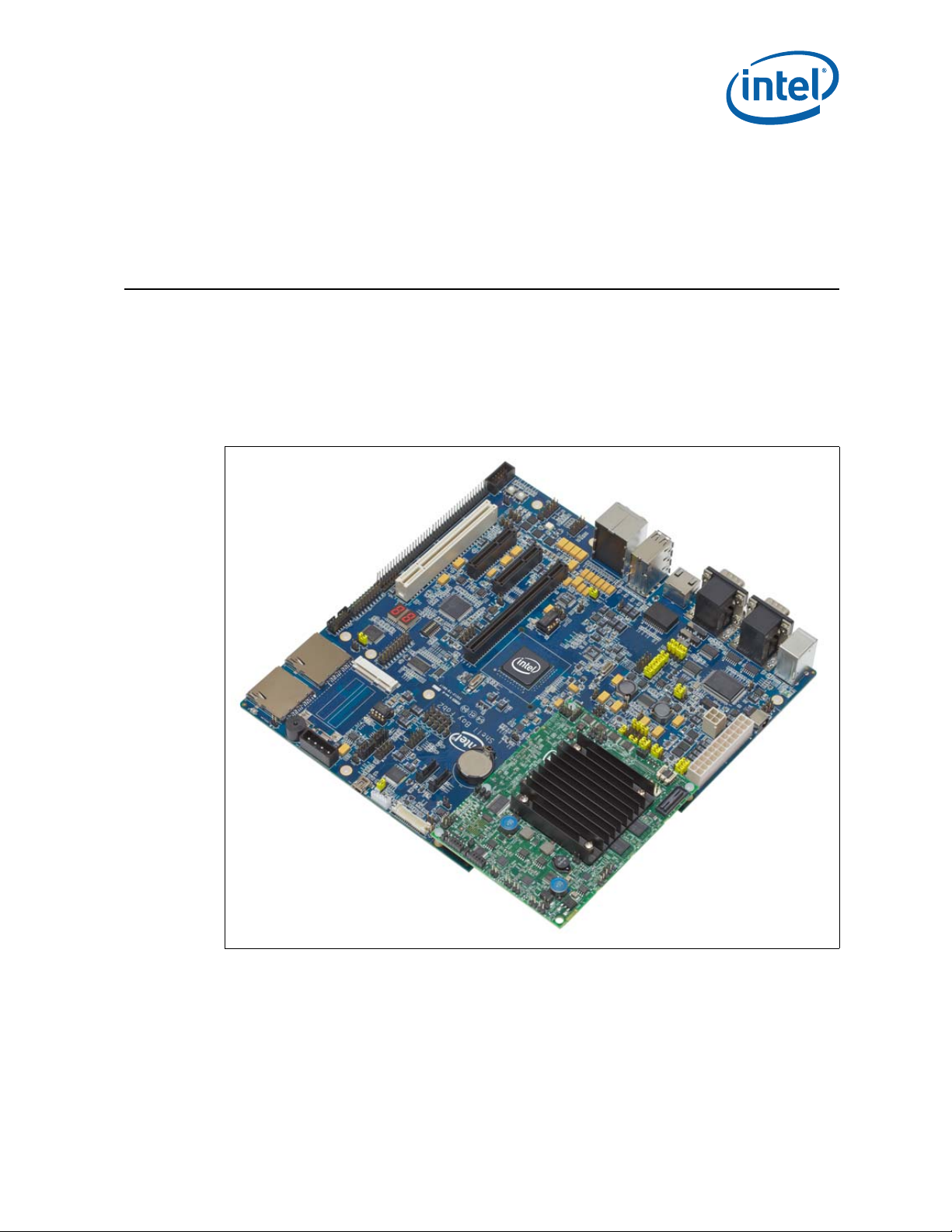
Figure 1. Intel® Atom™ Processor E660 with Intel® Platform Controller Hub EG20T
Development Kit
January 2012 User Manual
Document Number: 324213-002 13
Intel® Atom™ Processor E660 with Intel® Platform Controller Hub EG20T Development Kit
Page 14
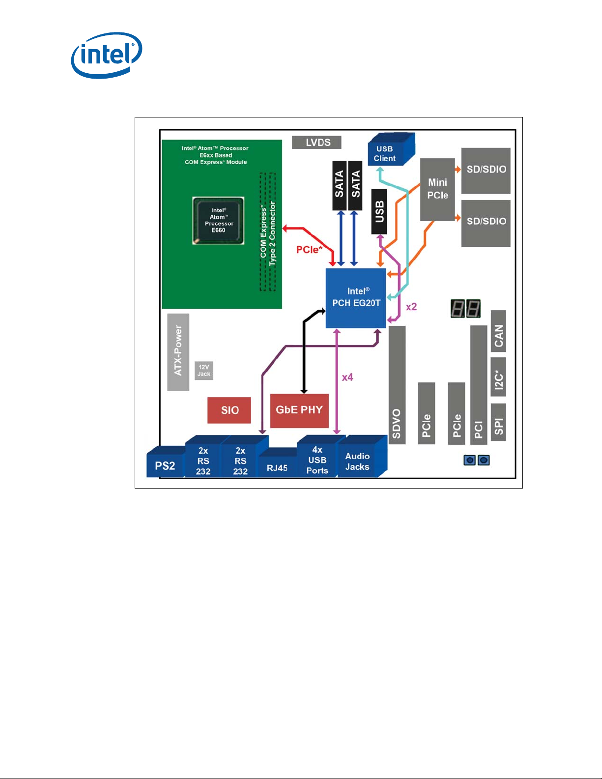
Figure 2. Block Diagram
Getting Started
Note: PCIe* x4 slots on ly have x1 co n n ection.
2.1 Overview
The development kit contains the Intel® Atom™ Processor E660 (populated on the COM
Express* module), other system board components and peripheral connectors and a
carrier board with the Intel
Note: The Intel
®
Atom™ Processor E660 with Intel® Platform Controller Hub EG20T
Development Kit is shipped as an open sy s tem, allowing maximum flexibility in
changing hardware configuration and peripherals. Since the boards are not in a
protective chassis , extra precaution is requ ired when handling and operating the
system. Review the document provided with the reference boards titled Important
Safety and Regulatory Information. This document contains additional safety warnings
and cautions.
®
Atom™ Processor E660 with Intel® Platform Controller Hub EG20T Development Kit
Intel
User Manual January 2012
14 Document Number: 324213-002
®
Platform Controller Hub EG20T.
Page 15

Getting Started
2.2 Major Features
Table 5 lists the major features of the development kit.
Table 5. Development Kit Feature Set Summary (Sheet 1 of 2)
Feature Board Implementation Comments
Supports 0.6 GHz (Ultra Low Power SKU), 1.0 GHz
®
Intel
Processor
CPU Voltage Regulator
Board Size
Memory
Main Clock IDT* ICS9LPRS436 CK505 compliant clock
Atom™ Processor E660 with 512KB L2
cache
®
Intel
Mobile Voltage Positioning 6 (Intel®
MVP 6)
Little Bay: 4.92 x 3.74 inch (125 x 95 mm)
Shell Bay: 9.6 x 8 inch (243.84 x 203.2 mm)
Single-channel DDR2, dual ranks, memory
down on PCB, 800 MT/s data rate
(Entry SKU), 1.3 GHz (Mainstream SKU) or 1.6 GHz
(Premium SKU) Intel
22 X 22 mm FCBGA package with 0.8 mm diagonal
ball pitch and 676 pins.
Single phase voltage regulators (U5C1, U5B2) on the
COM Expr e ss module.
Doubled-sided placement.
Supports up to 2-GB of system memory, eight SDRAM
devices max (4 on top and 4 on bottom), JEDEC
standard DDR2, soldered down memory only
U4D1 on the COM Express module, TSSOP, 48-pin
package
®
Atom™ Processor E660.
SPI
ITP Support Extended Debug Port (XDP) J1A1 XDP connector
Platform Controller
Hub
COM Express* COM Express* (Type-2) Connector Interface to the COM Express* module
LVDS
SDVO
PCIe* slot
PCIe* Signal Switch 1 Pericom PI2PCIE212-D
PCIe* Mini Card
PCIe*-PCI Bridge 1 Pericom PI7C9X111SL
PCI slot 1 slot via PCIe*-PCI Bridge
SATA 2 ports from PCH
USB 2.0 Host
USB 2.0 Client 1 port from PCH Connector: Mini-B receptacle
GbE
SD/SDIO/MMC 2x SD Card slots with MMC (8bit) su pport
UART
SIO 1 SMSC LPC47M172
16Mbit SPI serial flash (SST25VF016B) on the
COM Express module for storing boot code
®
Intel
PCH EG20T x1 Connects to the COM Express* Mod ule by PC Ie * x1
1 connector (from COM Express* conne ctor)
(30pin)
1 slot of PCIe* x16 height vertical edge card
connector (PCIe* Graphics ) (f ro m C OM
Express* connector)
2 slots of PCIe* x4 height verti c a l edge ca r d
connector via Pericom PI2PCIE212-D signal
switch
1 slot (alternate with a PCIe* slot) via Pericom
PI2PCIE212-D signal switch
4 ports of Type A receptacle from PCH, 2
headers from PCH
1 port from PCH,
GMAC interface: RGMII
3xRS232C by DB-9 (1 of them from SIO),
1xRS485/RS232C selectable by DB-9 and
header with flow cont r ol , via RS t rans ce i ver,
1 port by header from PCH directly
2x4 header (J1A2) on the COM Express module for
DediProg SF100* programmer
Single 18/24-bit LVDS interface; Back Light Inverter
(BLI) and LED backlight suppor t.
Supports AD D 2-N cards
Each slot is assigned PCIe* x1 signals (Not using x4
signals)
SMI pin of P C H i s co nne ct e d t o C O M Ex p res s* p in C 63
for legacy USB support.
PHY chip:
1 Realtek RTL8211CL
RS-232C Transceiver: MAXIM MAX3245ECAI+
RS-485 Transceiver: MAXIM MAX3076EESD+
January 2012 User Manual
Document Number: 324213-002 15
Intel® Atom™ Processor E660 with Intel® Platform Controller Hub EG20T Development Kit
Page 16

Table 5. Development Kit Feature Set Summary (Sheet 2 of 2)
Feature Board Implementation Comments
PS/2 KB 1 port from SI O
PS/2 Mouse 1 port fr om SI O
Altera EPM570 MAXII system management
CPLD
7-segment LED 2 digits from CPLD From COM Express* conne ctor
Buzzer 1
LPC 1 header (20 - pi n ); for SI O and CPLD From COM Express* connector
®
ε
TPM
Intel
Validation Header 1 header (40-pin) From COM Express* connector
GPIO 1 header (12-pin) From PCH
Intel
®
HD Audio
β
7.1 Audio Jacks 1 port (Stereo Jack x 6) from Au dio Codec
2
I
C* 1 header (4-pin) fr om PCH
SPI 1 header (10-pin) from PCH
CAN 1 header (4-pin) from PCH via CAN transceiver Transceiver: NXP TJA1040T
JTAG Port 2 hea de r s (P C H (6-pin), CPLD(14 - pi n ))
Serial ROM
Clocks for PCH
Push buttons Power x 1, Reset x 1
PCB Specification
Temperature
Humidity
Power Supply
Power management
(ACPI)
CPLD on the COM Express module and POST
code display CPLD (Port 80h decode) on the
carrier board
POST code display CPLD: Xilinx XC9572XL
1 header (20-pin) From COM Express* connect or
1 header (10-pin) from Audio Codec 1 Realtek ALC888 CODEC
DIP 8-pin socket x 1 to store SAT A Option ROM
& Ethernet MAC Address
SPI EEPROM: Microchip 25LC512-I/P
SYSCLK: Osc (25MHz)
Crystal Oscillator: 3
CLK Buffer: 1 (for PCIe*)
CLK Generator: 1 (for SATA)
USBCLK: Osc (48MHz)
UARTCLK: Osc (1.8432MHz)
SATACLK: CLK Gen (75MHz)
PCIeCLK: CLK Buff (100MHz)
8 layers, thickness: 63 mils (1.6mm), Halogen
Free Multilayer Material
Operation: 0 to 40°C
Storage: -20 to 85°C
All components are RoHS compliant
Operation: 20 to 80%
Storage: 5 to 95%
ATX connector x1
12V AT X connector x1
DC Jack: for AC Adapter (+12V, 5A)x1
Power indicated LED and header
CMOS Battery (CR2032) x1
S0 – Power On
ACPI Compliant
S3 – Suspend to RAM
(S4 – Suspend to Disk)
S5 – Soft Off
Getting Started
®
Atom™ Processor E660 with Intel® Platform Controller Hub EG20T Development Kit
Intel
User Manual January 2012
16 Document Number: 324213-002
Page 17

Getting Started
2.3 Processor Support
The COM Express* module comes with 1.3 GHz Intel® Atom™ Processor E660 with
512-KB cache in a 676 pins, FCBGA package.
Note: A heatsink is required for the 1.0 GHz or above processor SKU during room
temperature ambien t operation.
2.3.1 Processor Voltage Regulators
The COM Express* modu le us es an on board In tel® MVP6 single-phase regulator for the
processor core supply. The I/O voltage is 1.05 V.
2.4 COM Express* Module Support
The carrier board supports the COM Express* module with the Intel® Atom™ Processor
E660. A heatsink is required for the 1.0 GHz or above processor SKUs during room
temperature ambien t operation.
2.5 Subsystem Descriptions
Subsystem features refer to the component, slot and connector locations on the carrier
board. Component, slot and connector locations are la b eled with a letter-num b er
combination. Refer to the silkscreen labeling on the carrier board for location details.
Refer to Chapter 4.0 for more information.
2.5.1 Intel® Atom™ Processor E660
• Single channel 32-bit DDR2 memory interface running at 800 MT/s
• Four PCI Express* ports, x1
•Intel
®
HD Audio
β
• One channel 18- or 24-bit LVDS
•One channel SDVO
•SPI bus
2.5.2 COM Express* Connector
The carrier board contains a COM Express* interface connector for stacking the COM
Express* module. This connector is based on the Type 2 pinout, which is defined in the
*
COM Express* specification by PICMG
However, the carrier board does not support several functions in this pinout. Table 6
lists the COM Express* interface functions supported on the carrier board.
Table 6. COM Express* Interface Implemented Signals (Sheet 1 of 2)
COM Express*
Function
LVDS A&B ch, dedicated I
VGA 1ch, Analog RGB, dedicated DDC No support
TV-Out 1ch, Composite Video, S-Video, Component Video No support
LAN 1 port, Gigabit or 100/10 Base No support
SATA 4 ports, SATA 150-300 No support
Type 2 Description Carrier Board
.
2
C* A channel only
1
1
1
1
January 2012 User Manual
Document Number: 324213-002 17
Intel® Atom™ Processor E660 with Intel® Platform Controller Hub EG20T Development Kit
Page 18
Table 6. COM Express* Interface Implemented Signals (Sheet 2 of 2)
Getting Started
COM Express*
Function
ExpressCard* 2 ports, Tx/Rx is shared with PCI Express* No support
PCI Express* 6 ports, PCIe* REFCLK 4 ports
USB 2.0 8 ports, Over C urr e n t dete ct i o n No support
LPC 1 port, Low Pin Count Interface
®
HD
AC’97/ Intel
β
Audio
2
I
C* 1ch, Inter-Integrated Circuit
SMB 1ch, System Management Bus
PCI 1 port, PCI Bus 32bit 33/66MHz No support
PATA 1 port, Parallel ATA100 No support
PCI Express*
Graphics (SDVO)
Notes:
1. The associated signa ls a r e not con n e ct e d.
1 port, Audio Codec ’97, Intel® High Definition Audi oβ
Interface
1 port, Share with SDVO dedicated I2C* and PCI
Express* Graphics x16
Type 2 Description Carrier Board
2.5.3 Intel® Platform Controller Hub EG20T
The Intel® PCH EG20T was developed for IO extension of the processor. The features
of the Intel® PCH EG20T provide the func ti onality necessary for storage and
connectivity as well as functionality normally associated with handheld devices such as
SDIO/MMC and USB device.The Intel
• Interface to processor of PCI Express* x1 lane (Gen1)
• One GMAC interface for Gigabit Ethernet
• Two SATA ports, Gen2
• Six USB 2.0HS Host compatible ports
• One USB 2.0HS Client co m patible port
• Two SDIO/MMC interfaces
• Four UART interfaces
•One CAN interface
• One Serial Peripheral Interface (SPI)
2
•One I
C* interface
•One 12-bit GPIO interface
• One SPI Serial ROM interface
®
PCH EG20T has several functions as follows:
1
1
Super I/O (PS2),
CPLD (POST Indication),
Pin Header
Audio Codec IC
Option EEPROM for PCI Bridge
IC
PCIe*/miniPCIe/SDVO/
PCI/SIO/PCIe* CLK Buff/PCI
Bridge IC
1
1
SDVO (PEG) slot
®
Note: For details, see the Intel
Platform Controller Hub EG20T Datasheet.
2.5.4 System Memory
• Supports DDR2 soldered down memory.
• Supports 800 MHz memory bus frequencies.
®
Atom™ Processor E660 with Intel® Platform Controller Hub EG20T Development Kit
Intel
User Manual January 2012
18 Document Number: 324213-002
Page 19
Getting Started
2.5.5 Display
The carrier board has two options for display as follows. Refer to Figure 11 for the
location.
• LVDS – location is X4
• SDVO – location is X9
®
Note: The Intel
Development K it s upport s singl e c hanne l LVDS only . Table 7 lists th e displays that have
been tested with the kit.
Table 7. Supported LVDS Display s
Atom™ Processor E660 with Intel® Platform Controller Hub EG20T
Manufacturer Size Resolution Back Light
LG Display
(18-bit color)
AUO Display
(24-bit color)
Notes:
1. The protective tape on top of the LVDS connector must be removed prior to installing an LVDS cable.
2. VGA outpu t is n o t dir e ctl y su pp orted. Customers can use PC I Ex p res s*- b ase d x1 di scr ete e xte rn al 3D
graphics cards, or a third -pa r t y com ponent available on an ADD2-N card thr ou gh t h e S DVO interface.
13 inch
(330.2 mm)
8.4 inch
(213.4 mm)
1366 x 768 LED 16:9 LP140WH1- TLA 1
800 x 600 LED 4:3 G084SN05 V8
2.5.6 PCI Express* Slots/ PCI* Slots
• Two PCIe* x1 ports connect to x4 PCIe* slots (X10, X52) for add-in cards.
The X10 slot is alternately used with a PCIe* mini card slot (X8).
• One PCIe* mini card slot (X8) for mini PCIe* card module. This slot is alternately
used with PCIe* slot (X10).
• One PCI slot (X12) for PCI add-in card
• One PCIe* signal switch is used to alternate between the connected devices
• The PCIe* bus complies with the PCI Express* Rev. 1.0a specification.
Figure 3 describes the carrier board PCIe* connection.
Aspect
Ratio
Part#
January 2012 User Manual
Document Number: 324213-002 19
Intel® Atom™ Processor E660 with Intel® Platform Controller Hub EG20T Development Kit
Page 20
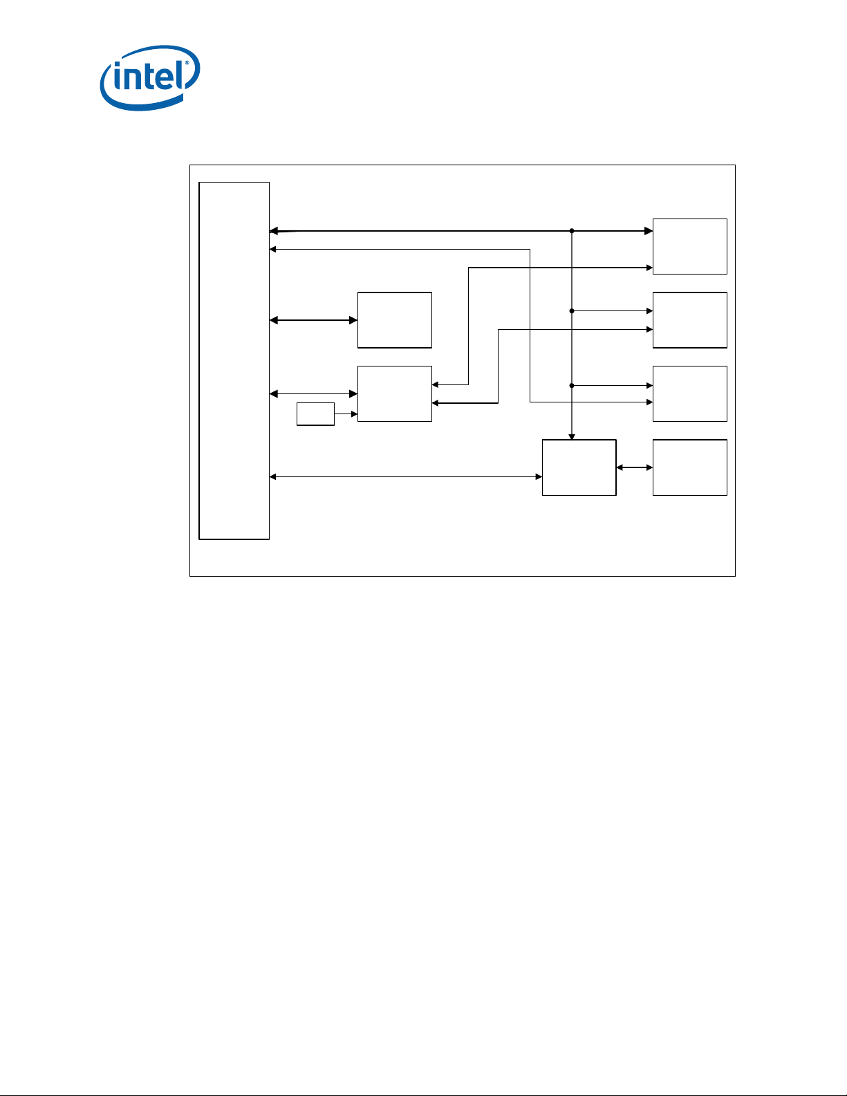
Figure 3. PCI Express* Block Diagram of the Carrier Board
SMB_Bus
Intel® PCH
EG20T
PCIe*
Signal Swi t ch
miniPCIe*
slot (X8)
PCIe* Lane0
PCIe* Lane3
PCIe* slot #3
(X10)
PCIe* slot #2
(X52)
PCI slot #4
(X12)
PCIe* to PCI
Bridge IC
PCIe* Lane3(*1)
PCIe* Lane3(*1)
PCIe* Lane2
PCIe* Lane1
(*1): The PCIe* lane can be alternately used by the signal switch selec t ion.
DipSW
SW4-bit1
COMe*
Connector
Getting Started
2.5.7 SATA Connectors
The carrier board provides two SATA connectors. These connectors (X29, X30) are
connected to the Intel
There is one peripheral power connector (X48) provided for the purpose of powering
external devices such as a SATA drive.
Figure 4 describes the carrier board SATA interface connection.
®
Atom™ Processor E660 with Intel® Platform Controller Hub EG20T Development Kit
Intel
User Manual January 2012
20 Document Number: 324213-002
®
PCH EG20T for SATA Gen 1 or Gen2 compliance devices.
Page 21

Getting Started
In te l® PC H
EG 20T
SATA #1
Connector
(X2 9 )
SATA ch0
SATA0 TX/RX
SATA0_LED
D5
SATA #2
Connector
(X 3 0)
SATA ch1
SATA1 TX/RX
SATA1_LED
D6
SIO
SMSC I/O
HDD_Indicator
PinHeader
X44
1
3
D50VS
330
D33VS
75
D33VS
75
Figure 4. SATA Block Diagram in the Carrier Board
2.5.8 USB Connectors
The carrier board has six USB Host ports with stackable standard Type-A receptacles
(X20 – X23) for rear panel, two USB Host ports with 10 pin header (X31) for front panel
and one USB client port with mini B receptacle (X45) for front panel. The functionality
of these ports are provided by the Intel
Note: The two USB Host ports that are routed to the front panel side’s pin header (X31) from
the Intel® PCH EG20T can be co nnected to the mi ni PCIe* slot. The m ini PCIe* slot
USB port is enabled by stuffing resistors on R409 and R410 and removing resistors on
R407 and R408.
Each USB Host port on the carrier board has a USB high side switch that is a low
current output type (ROHM BD2052AFJ* Continuous current load: 0.50A by a port) in
the VBUS output for the purpose of validating the Intel
additional power supply may be necessary depending on the USB device to connect.
Figure 5 describes the carrier board USB-Host interface connection.
®
PCH EG20T.
®
PCH EG20T. Therefore,
January 2012 User Manual
Document Number: 324213-002 21
Intel® Atom™ Processor E660 with Intel® Platform Controller Hub EG20T Development Kit
Page 22

Figure 5. USB-Host Block Diagram in the Carrier Board
Intel® P CH
EG20T
USB #2
Connector
(X2 3)
USB ch1
USB1
USB4
USB #3
Connector
(X2 2)
Hiside-SW
USB ch4
ENA
ENB
FLGA
FLGB
OUTB
OUTA
usbhost1_penc
usbhost4_penc
usbhost1_ovc
usbhost4_ovc
USB #4
Connector
(X2 1)
USB ch3
USB3
USB2
USB #5
Connector
(X2 0)
Hiside-SW
USB ch2
ENA
ENB
FLGA
FLGB
OUTB
OUTA
usbhost2_penc
usbhost3_penc
usbhost2_ovc
usbhost3_ovc
USB ch5
USB5
USB0
Hiside-SW
USB ch0
ENA
ENB
FLGA
FLGB
OUTB
OUTA
usbhost0_penc
usbhost5_penc
usbhost0_ovc
usbhost5_ovc
[ Back-Panel USB Host Receptacles ]
X23
X22
X21
X20
(front view )
D50VD33V
D50VD33V
D50VD33V
USB #7
miniPCIe Slot (X8)
USB #6, #7
10pin Pin
header
(X3 1)
(*1 )
(*1) USB #7 port in the miniPCIe Slot is available by mounting resistors on the empty resistor pads.
Getting Started
2.5.9 Gigabit Ethernet Connector
2.5.10 SD/SDIO/MMC
The carrier board provides one Gig a bit Ethernet inte r fa c e f r om the Intel® PCH EG20T
via a Realtek RTL8211CL* Gigabit Ethernet PHY transcei v er. The Gigabit Ethernet port
(X26) is routed to the rear I/O panel's stacked receptacle.
The carrier board provides tw o S D/ SDIO/MMC ports ( X5, X6) with the foll owing
features:
®
Atom™ Processor E660 with Intel® Platform Controller Hub EG20T Development Kit
Intel
User Manual January 2012
22 Document Number: 324213-002
• All ports are SD rev1.1 specification compliant and MMC rev4.0 specification
compliant.
• All ports operate to 48 MHz and su pport 8-bit oper a tion.
Page 23

Getting Started
2.5.11 UART
The carrier board provides five UART ports for use in the system.
Four UART ports are provided fr om the Intel
provided from the SIO (SMS C LPC4 7M172* ). The feat ures o f these p orts are as follows :
•Intel
—UART port 0:
—UART port 1-3:
— SIO (SMSC LPC47M172*)‘s UA RT feature:
®
PCH EG20T and one UART interface is
®
PCH EG20T UART feature:
— Assigned rear I/O panel’s D-Sub 9pin stacked connector (X19) via a RS-
232C transceiv er MAXIM MAX3245ECAI+* or via two RS485 transce iv ers
MAXIM MAX3076EESD*. The alternate selection is done by switches (SW1SW3) and jumpers (J16-J21) on the boar d. UART0 is connected to a 2x5
2.54mm pin header (X46) directly.
— Standard 165 50 Compatible UART with Send/Receive 256-Byt e F IF O s
— The receive FIFO generates 3-bit error data per byte
— Supports 300k and 4Mbps Baud Rate but X19 port supports up to 1Mbps
following RS- 232C transceiver’s specification.
— Programmabl e Baud Rate Generator
®
— Enables auto hardware flow control of the Intel
PCH EG20T
— Assigned rear I/O panel’s D-Sub 9pin stacked conn ectors (X17; UART2,
X18; UART 1) via a RS-232 C tr anscei ve r M AXI M MAX 3245 ECA I+*. UA RT3 is
connected to a 2x5 2.54mm pin header (X40) directly.
— Standard 165 50 Compatible UART with Send/R eceive 64-Byte FI FO s
— The receive FIFO generates 3-bit error data per byte
— Supports 300k and 1Mbps Baud Rate
— Programmabl e Baud Rate Generator
— Assigned rear I/O panel’s D-Sub 9pin stacked connector (X16) via a RS-
232C transceiver MAXIM MAX3245ECA I+ *.
— High Speed 16 C550A Compatible UART with Send/Receive 16-Byte FIF O s
— Supports 230k and 460k Baud Rate
— Programmabl e Baud Rate Generator
Figure 6 and Figure 7 describe the carrie r board UART interfac e connection.
January 2012 User Manual
Document Number: 324213-002 23
Intel® Atom™ Processor E660 with Intel® Platform Controller Hub EG20T Development Kit
Page 24

Figure 6. UART Block Diagram in the Carrier Board
Super IO*
SMSC
LPC47M172
10Pin-Header
(X40)
RS232C
D-sub9
Male-type
(X16)
UART x1port
Intel® PCH
EG20T
RS232C
Transceiver
RS232
D-sub9
Male-type
(X17)
UART x1port
RS232C
Transceiver
RS232
D-sub9
Male-type
(X18)
UART x1port
RS232C
Transceiver
RS232/
RS485
D-sub9
Male-type
(X19)
UART(with Flow
Control) x1port
RS232C
Transceiver
RS485
Transceiver
UART x1port
Back Panel
Connector
SW1-3 JP12-JP21
10pin-Header
(X46)
UART2
UART1
UART0
UART3
(*) For detail, see Figure 7
Getting Started
Note: For UART0 po rt, it is necessary to configure switches and jumpers for RS transceiver
selection. See Section 4.3.1 for details.
Caution: Do not change the setting after powering on the system. Be careful to configure proper
setting if the intention is to change the setting. A fault in the setting could damage the
platform, the in terconnecting ca ble, or the attache d external device.
®
Atom™ Processor E660 with Intel® Platform Controller Hub EG20T Development Kit
Intel
User Manual January 2012
24 Document Number: 324213-002
Page 25

Getting Started
DCD/GND
RXD/CTS+
D-Sub9pin
Connector (X19)
DTR/RXD+
TXD/RTS+
2
3
1
4
RS232C/RS 485
GND/RXD-
DSR/CTS-
RTS/RTS-
CTS/TXD+
RI/TXD-
5
6
7
8
9
MHS121
(SW3)
MAX3245E
MAX3076E
RE
DE
MAX3076E
RE
DE
DGND
DGND
DGND
DTR
DCD
DSR
RI
RTS
CTS
TXD
RXD
D33V
D33V
DGND
Intel® PCH
EG20T
10pin-Header
(X46)
J17
J18
J19
J20
J12
J13
J14
J15
J16
DGND
D33V
J21
MHS442
(SW1)
MHS442
(SW2)
Figure 7. Intel® Platform Controller Hub EG20T UART Port0 Connection Diagram in the
Carrier Board
Note: For the UART0 port, it is necessary to configure switches and jumpers for RS
transceiver selection. See Section 4.3.1 fo r detail s.
Caution: Do not change the se tting a fter pow ering on th e system . Be c are ful to c onfig ure pr oper
setting if the intention is to change the setting. A fault in the setting could damage the
2.5.12 I2C*
platform, the interconnecting cable, or the attached external device.
The carrier board provides one I2C* port from the Intel® PCH EG20T that conforms to
the typical I
2
C* bus specification. It operates as a master or slave device and supports
a multi-master bus. The Intel
January 2012 User Manual
Document Number: 324213-002 25
pin header (X37) and 2x5 2.54mm pin header (X38) directly.
Intel® Atom™ Processor E660 with Intel® Platform Controller Hub EG20T Development Kit
®
PCH EG20T I2C* port is connected to the 1x 4 2.54mm
Page 26

2.5.13 SPI
SPI serial flash device (P/N# SST25VF016B) on the COM Express module stores the
boot code. The boot fi rmware can be programmed through an in-system programming
tool from Dediprog . A 2x4 2.54 mm pin head er is provid ed on boar d for use to prog ram
the SPI flash. Refer to Chapter 5.0 for more information.
The carrier board provides on e s er ial peripheral interface (SP I) f r om the Intel
EG20T for use in the s ys tem. The Intel
2.54mm pin header (X38) directly.
This port can be used to connect the protocol analyzer of Total Phase Beagle*
2
C*/SPI/MDIO.
I
2.5.14 CAN
The carrier board provides a CAN interface from the Intel® PCH EG20T for use in th e
system. This CAN controller performs communication in accordance with BOSCH CAN
Protocol Version 2.0B Active
be programmed to a maximum of 1Mbit/s based on the technology used. Th e Intel
PCH EG20T CAN bus is connect ed to the 1x4 2.54mm pin header (X39) via CAN
transceiver NXP TJA1040T*.
Getting Started
®
®
PCH EG20T SPI is c onnected to the 2x5
1
(standard format and extended format). The bit rate can
PCH
®
When communicating in a CAN network, individual message objects (see the CAN
Message Objects section in the Message RAM section of the Intel
datasheet) are configured. The message objects and identifier masks for the receive
filter for the received messages are stored in the message RAM.
2.5.15 Serial ROM
The Intel® PCH EG20T provides Serial ROM interface for use of Option ROM data
loading through SPI. This Serial ROM inte r fa c e has the follow ing two roles.
• Initialization with hardware for Ethernet function and PCI configuration (Packet
Write mode).
— Initialization of MAC-address of Gigabit Ethernet
— Initialization of “Subsystem ID” or “Subsystem Vendor ID” of each PCI device in
the Intel
• Access to Option ROM space for SATA AHCI function (ROM mode).
It is used to support a single SPI compatible EEPROM device with 8pin DIP socket
(X32). This SP I EEPROM device ha s some limitati ons. The followin g a r e
requirements for selecting connectable SPI EEPROM:
— Supporting 5 MHz Read and Write
— Supporting Page Write Mode more than 4 bytes
— Memory size is up to 512 Kbit from 8 Kbit
Microchip 25LC512-I/P* meets the requirements mentioned above and is installed on
the SPI EEPROM Socket (X32 ) on th e c arrier board.
®
PCH EG20T
®
PCH EG20T
Note: Please use the following utilities for programming the Serial EEPROM for MAC address
or SATA AHCI Option ROM
(link: http://sourceforge.net/projects/generalembedded/files/
phub_util_orom.tar.b
—
— phub_util_mac.tar.bz
z2
2
)
1. Defined by ISO 11519, ISO 11898, and SAEJ2411.
®
Atom™ Processor E660 with Intel® Platform Controller Hub EG20T Development Kit
Intel
User Manual January 2012
26 Document Number: 324213-002
Page 27

Getting Started
2.5.16 LPC Bus
The LPC bus connects to these devices on the car r ier board:
• SMSC LPC47M172 Super I/O*
• Xilinx XC9572XL* POST code display CPLD
•Intel
• LPC debug header for LPC testing (X34)
®
TPMε header (X35)
Note: LPC DMA is not supported by the processor on the Intel® Atom™ Processor E660 with
®
Platform Controller Hub EG20T Development Kit.
Intel
2.5.16.1 Super IO (SIO)
The LPC47M17 2 s er ves a s leg a c y PS / 2 * keyboard and mouse c ontroller on the ca r r ier
board. The LPC47M172 Super I/O suppo rts:
•LPC interface
• One UART serial port at the rear I/O panel (see Section 2.4.10 )
• Two PS/2 ports located at the rear I/O panel
2.5.16.2 POST Code Display CPLD
I/O writes to port 80h on LPC bus are de coded by the Xilinx XC957 2X L* device on the
carrier board and displayed on tw o 7-segment LEDs.
2.5.16.3 Intel® Trusted Platform Moduleε (Intel® TPMε) Header
The carrier board implements a head er (X35) that supports Intel® TPMε 1.2
specification compliant d evices.
2.5.17 Intel® High Definition Audioβ (Intel® HD Audioβ)
The Intel® HD Audioβ is enabled through the Realtek ALC888* CODEC. Six port Intel®
HD Audio
provided on the carrier board. For the front panel, only a 2x5 header (X36) is provided.
β
jack (X27) is provided on the rear I/O panel. No SPDIF receptacle is
2.5.18 Clocks
The COM Express* Module uses a CK-505 clock solution. The BSEL [2:1] signals driven
by the processor are used by the C K-505 to configure the processor external referen ce
clock.
The carrier board uses several clocks. Figure 8 describes the clock circuit connections in
the carrier board. Figure 9 describes the change req uired to connect th e Intel
EG20T clock circuit in the carrier board when using the custom CK505 clock generator
on the COM Expres s module.
Intel® Atom™ Processor E660 with Intel® Platform Controller Hub EG20T Development Kit
January 2012 User Manual
Document Number: 324213-002 27
®
PCH
Page 28

Figure 8. Clock Circuit Diagram in the Carrier Board
USB_CLK
Intel® P CH EG20T
SYSCLK
25.0MHz
SPXO
COMe*
Connector
48MHz
SPXO
UART_CLK
1.8432MHz
SPXO
(DIP S ocket)
GbE-PHY
TXC
RXC
25.0MHz
X’tal
125MHz
50MHz
I2C
400KHz
5MHz
SMB_CK
SMB_DAT
PCIE0_CK_REF+/-
PC Ie to P CI Bridge
PC Ie *slot #2,# 3 /
min i P CIe slot
PCI slot #4
33MHz
SD-card
SPI
4MHz(*1)
UART
1MHz
CAN
75.0MHz
LVDS_CG
PCIe_CLKT
PCIe_CLKC
SATA_CLKT
SATA_CLKC
25MHz
X’tal
125MHz
CPLD
GCLK0
XTAL1
Codec
XTAL2
48kHz
HDA SYNC
12.228MHz
HDA BITCLK
LPC_33MHZ _CLK
LPC Header
LPC_CLK
PCI CLK
SIO (SMSC 47M172)
33MHz
CLOCKI
CLOCKI32
32.768kHz
SPXO
14.318MHz
SPXO
MCLK/
KCLK
PS/2
KB/MOUSE
LVDS_A/B_CK+/-
*1: One of the UART port is up to 4Mbps baud rate clock, the other ports are up to 1Mbps.
TPM_33MHZ_CLK
TPM Header
LVDS_I2C_CK
LVDS Connector
SDVO_CLK
SDVO_DATA
SDVO slot
LVDS_I2C_DAT
LPC_CLKRUN_N
LPC_CLKRUN_N
PCI_CLKRUN#
EMPTY
CLK
Buffer
(*2)
*2: LPC CLK B u f fe r is n o PLL loc ke d type. (e.g. ICS 553 )
100MHz
PCIe*
CLK
Buffer
Getting Started
®
Intel
User Manual January 2012
28 Document Number: 324213-002
Atom™ Processor E660 with Intel® Platform Controller Hub EG20T Development Kit
Page 29

Getting Started
USB_CLK
Intel® PCH
EG20T
SYSCLK
25.0MHz
SPXO
COMe*
Connector
100MHz
PCIe* CLK
Buffer
48MHz
SPXO
UART_CLK
1.8432MHz
SPXO
(DIP Socket)
SMB_CK/DAT
PCIe REFCLK_P/N
75.0MHz
LVDS_ICG
PCIe_CL KT
PCIe_CL KC
SATA_CLKT
SATA_CLKC
25MHz
X’tal
EMPTY(*)
IOH_EC_CLK
C77
N.C
IOH_USB_CLK
C83
IOH_SYS_CLK
C97
IOH_SATA_CLKJ_P
D64
IOH_SATA_CLKJ_N
D63
IOH_I2S_CLK
D83
N.C
22ohm(*)
22ohm
22ohm
EMPTY(*)
22ohm(*)
22ohm
R1a
R1b
R2a R2b
R3a R3b
D33VS
Cc
Cc
SATA CLK
Source
On board
LVDS_CG
COMe Module
CK505
R1a 22ohm EMPTY
R1b 22ohm EMPTY
R2a EMPTY 10Kohm +/-10%
R2b EMPTY 10Kohm +/-10%
R3a EMPTY 5.6Kohm +/-10%
R3b EMPTY 5. 6Kohm +/-10%
Cc EMPTY 0.1uF
(*) In the case to use the custom CK505 on the Little Bay
these resistors need to change mounting.
Figure 9. Clock Changing Circuit Diagram for the Intel
in the Carrier Board
®
Platform Controller Hub EG20T
2.5.19 Real Time Clock
An on-board bat tery on the carrier boa r d m a intains power to the real time clock ( RTC)
on the COM Express module when in mechanical off state (G3 state).
2.5.20 In-Target Probe (ITP) and Debug Support
The development kit provides on-board ITP support with an XDP connector on the COM
Express* Module. You can debug from the reset vector without EFI or OS dependency
(up to OS functi onality). Ports 80-83 ar e pr ovided as a troubleshooting to ol to monitor
POST output during EFI execution.
®
ITP requires that the CMC be loaded to configure the Intel
before register accesses can be made. The CMC code resides in the SPI flash on the
COM Express* module. The SPI flash must be programmed to use ITP.
Intel® Atom™ Processor E660 with Intel® Platform Controller Hub EG20T Development Kit
January 2012 User Manual
Document Number: 324213-002 29
Atom™ Proce s s or E660
Page 30

2.5.21 Power Supply Solution
The development kit can be po wered from an ATX power supply (desktop solution) that
contains all of the voltage regulators necessary to power the system up. Additionally,
battery or AC adapter support is provi ded through +12VDC input.
The characteristic of using AC adapter or battery pack is slightly different from using an
ATX po wer supply:
• Due to the low cur ren t ra tin g of the A C adap ter, the car ri er boa rd do es no t sup por t
a full load of extens ion slots (SDVO , 2 PCIe* and PCI slots ) . When using these
extension slots, please use an ATX power supply.
• In the case of using the AC adapter, it is recommended that the carrier board be
connected to the LVDS LCD module and an external 2.5" hard disk only. When
using AC adapter, please supply power to the hard disk using the power supply
connector (X48) on the carrier board. If using the X48 connector, the customer
must prepare a hard disk power cable that converts to the adaptive connector.
• Using the AC adapter is allowed as long as the total of the system current
consumption is not beyond the rating output of the used AC adapter. Please use
available AC adapter that has the rating output of 6.5A or less.
Getting Started
Note: Use an UL94V-1 minimum compliant AC adapter that provides 80 Watts of continuous
output power. For example, the Sinp ro Electronics Mo del No. SPU80-105* meets this
requirement.
Use an ATX12V 1.1 specification compliant power supply regardless of maker or
wattage level (an ATX12V rating means V5 min current =0.1 A vs. an ATX V5 min
current = 1.0 A, among other differences). For example, the Sparkle* Model No.
FSP300-60BTV meets this requirement and is an ATX12V 1.1 specification compliant
power supply.
If the power switch on the ATX power supply is used to shut down the system, wait at
least 5 seconds before turning the system on again.
The recommended way to shut down the board is through software or by pressing and
holding the power button switch (SW5) for 5 seconds until the power supply turns off.
Using the power supply switch or pulling the plug out of the wall is not recommended.
2.5.22 Board Size
The form factor of the carrier board follows Micro ATX 9.6 x 8 inch (243.84mm x
203.2mm) specification. The back panel jacks may not conform to ATX specifications.
§ §
®
Atom™ Processor E660 with Intel® Platform Controller Hub EG20T Development Kit
Intel
User Manual January 2012
30 Document Number: 324213-002
Page 31
Power Management
3.0 Power Management
3.1 Power Measurement Support
The development kit has power measurement for each IO circuit and device validation.
Power measurement resistors are provided to measure the pow er on man y o f th e
subsystems. Table 8 lists the measurement resistors.
Table 8. Power Measurement Resistors
Feature Resistor-1 Resistor-2 Resistor-3
Tolerance 1% 1% 5%
Value 10 m
Watt 0.5W 0.75W 2W
Package Size (inch) 0805 1206 2512
Ω
10 m
Ω
2 m
Ω
Note: Intel recommends that larger (~10 mΩ) resistors be stuffed for greater accuracy.
Power on a particular subsystem is calculated using the following formula:
2
Equation 1. P = V
/R
R = value of the sens e res istor (typically 0.01 Ω)
V = the voltage difference measured across the sense resistor .
Use a high precision digital multi-meter tool such as the Agilent 34401A digital multi-
meter.
Refer to Table 9 for a comparison of a high-precision, digital multi-meter (Agilent
34401A) versus a pr ec ision, digital multi-meter (Fl uke 79).
January 2012 User Manual
Document Number: 324213-002 31
Intel® Atom™ Processor E660 with Intel® Platform Controller Hub EG20T Development Kit
Page 32

Table 9. Digital Multi-Meter Comparison
Example System
Sense Resistor Value 0.01 Ohm
Voltage Difference Across Resistor 1.492 mV (149.2 mA)
Calculated Power 0.223 mW
Power Management
Digital Multimeter
Specification
Min voltage displaye d Ca l culated
power
Max voltage displayed Calcul a te d
power
Error in power +/- 0.009% +/- 0.3%
Note: The precision achieved by using a high precision digital multi-meter versus a normal digital multi-
meter is ~33 times more accurate.
(+/- 0.0030% of reading) + (+/-
0.0030% of range)
1.49193 mV
0.22258 mW
1.49206 mV
0.22624 mW
Agilent 34401A
1/2
digit display)
(6
0.09% +/- 2 digits
1.47 mV
0.216 m
1.51 mV
0.228 mW
Fluke 79
(3 digit display)
Table 10 summarizes all the power measurement sense resistors located on the carrier
board. All sense resistors are 0.01 Ω unle s s otherwise noted.
Table 10. Carrier Board Voltage Rails (Sheet 1 of 3)
Schem
Page
13 PCIe* Slot #2 12V D120Vslot D120VSlot_PCIE_SLOT2 R35 Resistor-2
13 PCIe* Slot #2 3.3V D33VSlot D33VSlot_PCIE_SLOT2 R37 Resistor-2
13 PCIe* Slot #2 3.3V D33V D33V_PCIE_SLOT2 R38 Resistor-1
13 PCIe* mini Card 1.5V D15VS D15VS_EXCD_MINI R40 Resistor-1
13 PCIe* mini Card 3.3V D33V D33V_EXCD_MINI R42 Resistor-1
14 PEG Slot #1 SDVO 12V D120VSlot D120VSlot_SDVO R48 Resistor-2
14 PEG Slot #1 SDVO 3.3V D33VSlot D33VSlot_SDVO R49 Resistor-2
15 PCIe* Slot #3 12V D120VSlot D120VSlot_PCIE_SLOT3 R391 Resistor-2
15 PCIe* Slot #3 3.3V D33VSlot D33VSlot_PCIE_SLOT3 R392 Resistor-2
15 PCIe* Slot #3 3.3V D33V D33V_PCIE_SLOT3 R390 Resistor-1
19 LVDS 12V D120VS D12VS(1pin: VDD_BLI) R269 Resistor-1
19 LVDS 5.0V D50VS D50VS(4pin: VDD_DBC) R270 Resi stor - 1
19 LVDS 3.3V D33VS D33VS(18pin: VDD_VCL) R274 Resistor-1
19 LVDS 3.3V D33VS
22 SATA_HDD 5.0V D50VS_HDD D50VS for HDD_POW R405 Resistor-2
23 SD Slot 1(X5) 3.3V D33VS D33VS_SD_SLOT0 R299 Resistor-1
23 SD Slot 2(X6) 3.3V D33VS D33_VS_SD_SLOT1 R395 Resistor-1
26
Target Component Voltage
Hiside SW for
D50V_D50VS_USB_Port2,3
5.0V
Supply
Power Rail
D50V_D50VS
_USB2_5
Rail Ref Des
D33VS_LVDS_VDDVDL
(16,17pin: VDD_VD L 1 ,2 )
Hiside SW Pow for
D50V_D50VS_USB_Port2, 3R151 Resistor-1
R275 Resistor-1
Resistor
Spec
®
Atom™ Processor E660 with Intel® Platform Controller Hub EG20T Development Kit
Intel
User Manual January 2012
32 Document Number: 324213-002
Page 33

Power Management
Table 10. Carrier Board Vol t age Rails (Sheet 2 of 3)
Schem
Page
26
27
28
35 Intel
35 Intel
35 Intel
Target Component Voltage
Hiside SW for
D50V_D50VS_USB_Port4,5
Hiside SW for
D50V_D50VS_USB_Port0,1
Hiside SW for
D50V_D50VS_USB_Port6,7
®
TPMε Header 5.0V D50VS
®
TPMε Header 3.3V D33VS
®
TPMε Header 3.3V D33VA
5.0V
5.0V
5.0V
Supply
Power Rail
D50V_D50VS
_USB2_5
D50V_D50VS
_USB_SIO
D50V_D50VS
_USB6_7
Rail Ref Des
Hiside SW Pow for
D50V_D50VS_USB_Port4,5R158 Resistor-1
Hiside SW Pow for
D50V_D50VS_USB_Port0,1R155 Resistor-1
Hiside SW Pow for
D50V_D50VS_USB_Port6,7R163 Resistor-1
D50VS for Intel
Header(6pin)
D33VS for Intel
Header (9pin)
D33VA for Intel
Header (15pin)
®
TPMε
®
TPMε
®
TPMε
R278 Resistor-1
R279 Resistor-1
R283 Resistor-1
Resistor
36 AUX Pow Supply 12V AUX_+12V ATX_+12V R402 Resistor-3
P-ch MOSFET(Q19) for D50VA
37
and +5VB_D50VA
5.0V D120VA D50VA via Power SW Reg R396 Resistor-3
37 P-ch MOSFET(Q26) for D33VA 3.3V D120VA D33VA via Power SW Reg R397 Resistor-3
Power Switch for D50V, D50VS,
D50DS_HDD,
D50V_D50VS_USB2_5,
D50V_D50VS_USB6_7 and
37
D50V_D50VS_USB_SIO,
5.0V D120VA +5VB_D50VA and D50VA R398 Resistor-3
Validation Header (X33),FP
Header (X44), COM Express*
Conn (XAB)
Reset IC for D33VA_D33V,D25VA
DLY, Reset IC for
D33V_D33VS,D50V_D50VS DL Y,
Reset IC for D33VS DLY,
Switching Regulator for D12VA,
FET-SW for D33VA_D33V, LDO
Regulator for D25VA, F ET -SW for
D33VA_D33VS, FET-SW for
37
D33VS, FET-SW for D12V, FET-
3.3V D120VA D33VA R399 Resistor-3
SW for D33V, LDO Regulator for
D18VS,LDO Regulator for D10V,
LDO Regulator for D15VS, FETSW for D10VS, FET-SW for
D12VS, Intel
POW LED(D1), PCI Bridge
®
TPMε Header,
EEPROM Sel, CK505 for PCH
PWR_OK Circuit,D50VA FET
Circuit (Q19, Q20),D33VA FET
Circuit (Q26, Q25),D120VS FET
38
Circuit (Q11),D120VSlot FET
Circuit (Q21),Switching
12V
ATX_+12V or
DC_+12V
D120VA R294 Resistor-3
Regulator for D50VA,D33VA
(U61)
25MHz OSC for PCH, GbE PHY,
43
GbE LED,PCH(PLA), GbE Reset IC
PCH UART CLK, PCH(PLB),LPC
43
CLK Buf, SIO ,32.768kHz OSC for
3.3V D33VA D33VA_D33V R435 Resistor-1
3.3V D33VA D33V_D33VS R536 Resistor-1
SIO,RS232C Drv, RS485 Drv
43 PCH(PLA), GbE-PHY 2.5V D33VA D25VA R535 Resistor-1
Spec
January 2012 User Manual
Intel® Atom™ Processor E660 with Intel® Platform Controller Hub EG20T Development Kit
Document Number: 324213-002 33
Page 34

Table 10. Carrier Board Voltage Rails (Sheet 3 of 3)
Power Management
Schem
Page
43
43
44
44
44
44
44 PCIe* Signal SW 1.8V D33VA D18VS R318 Resistor-1
44
44
44
44 PC Ie* to PCI Bridge 1.0V D10V D10VS R540 Resistor-1
Target Component Voltage
FET-SW for D12V,FET-SW for
D12VS,PCH(PLA),Reset IC for
PCH IOVDDA
PCH(PLB), Reset IC for PCH
IOVDDB
PCIe* Slot #2, PCIe* mini Card,
PEG Slot #1 SDVO, PCIe* Slot
#3, PCIe * to PCI B ridg e, PCI S lot
#4, Power_LED(D2)
LVDS, SIO, Audio Codec, CAN
Driver, SPI Header, Intel
Header, Validation Header, FP
Header, Speaker
COM Express* (PU),
SATA_CLK_Gen, PCH(PLC),
PCIe_CLK_Buf, PCIe* Slot #2,
PCIe* mini Card LED, PCIe* Slot
#3, SW4_PU, PCIe* to PCI
Bridge, EEPROM, LVDS,
SATA_LED, SD_Conn, S IO,
LPC_CLK_Buf, Audio_Codec,
HAD_Header, RS232C_Driver,
RS485_Driver, I
Header, C PLD, Intel
Header, PCH Internal Monitor
Header, Power_LED
COM Express* Conn (XAB, X CD),
LVDS, SATA_ POW, PWOK_Gen
COM Express* CARD Powe r SW,
PCIe* mini Card
PCIe* to PCI Bridge, FET-SW for
D10VS
PCH(PLC), Reset IC for PCH
IOVDDC
®
TPMε
2
C* Header, SPI
®
TPMε
1.2V D33VA D12VA R537 Resistor-1
1.2V D12VA D12V R538 Resistor-1
3.3V D33VA D33V R306 Resistor-2
5.0V D50VA D50VS R309 Resistor-2
3.3V D33VA D33VS R310 Resistor-2
12V D120VA D120VS R311 Resistor-3
1.5V D33VA D15VS R319 Resistor-2
1.0V D33VA D10V R357 Resistor-1
1.2V D12VA D12VS R539 Resistor-1
Supply
Power Rail
Rail Ref Des
Resistor
Spec
§ §
®
Atom™ Processor E660 with Intel® Platform Controller Hub EG20T Development Kit
Intel
User Manual January 2012
34 Document Number: 324213-002
Page 35

Reference Board Summary
Atom™
E660
DDR2
DDR2
SPI
Clo ck Chip
Thermal
Sensor
Thermal
Sensor
XDP
LEDS
COM
Express
(Bottom)
CPLD-SMC
(Bottom)
Intel®
Atom™
Processor
E660
Intel®
Atom™
Processor
E660
4.0 Reference Board Summary
4.1 Intel® Atom™ Processor E6 60 with Intel® Platform Controller Hub EG20T Development Kit Features
Figure 10. COM Express* Module Components (Top View)
January 2012 User Manual
Document Number: 324213-002 35
Intel® Atom™ Processor E660 with Intel® Platform Controller Hub EG20T Development Kit
Page 36

Figure 11. Carrier Board Feature Placement
Reference Board Summary
4.2 Connectors
This section describes the board’s connectors. Figure 12 shows the location number of
the connectors (including back panel side) on the board. Table 11 lists connectors’
labels and names.
Caution: Most of these connectors are not over-current protected. Do not use these connectors
®
Atom™ Processor E660 with Intel® Platform Controller Hub EG20T Development Kit
Intel
User Manual January 2012
36 Document Number: 324213-002
for powering devices external to the computer chassis. A fault in the load presented by
the external devices could damage the computer, the interconnecting cable, or the
attached external device.
Page 37

Reference Board Summary
X4
X5
X6
X8
X53
X48
X5 1,X49
X50
X1 4
X1 5
X1 6
X1 7
X18
X19
X26
X20
X21
X22
X23
X27
X1 4
X1 5
X17
X16
X1 9
X18
X26
X23
X22
X21
X20
X27
X32 X13
X4 5
Figure 12. Carrier Board Connectors
X3 9
X3 0
X2 9
XA B
XC D
X4 4
X3 7
X31
X43
X35
X34
X1
X2
X3
X46
X9
X10
X52
X3 6
X40
X4 2
X33
X12
X41
X3 8
January 2012 User Manual
Document Number: 324213-002 37
Intel® Atom™ Processor E660 with Intel® Platform Controller Hub EG20T Development Kit
Page 38

Table 11. Carrier Board Connectors
Label Connector Name Label Connector Name
XAB
XCD
X1 ATX Power X33 Validation Header
X2 AUX Power X34 LPC Header
X3 12V DC -Jack X35 Intel
X4 LVDS X36 Intel® HD Audioβ Header
X5 SD slot1 X37 I
X6 SD slot2 X38 SPI
X8 miniPC Ie* slot X39 CAN
X9
X10 PCI Express* x4; Slot#3 X41 PCH Validation Header
X12 PCI; Slot#4 X42 JTAG from PCH
X13 Battery Holder X43 JTAG from CPLD
X14 PS/2 Mouse X44 Front Panel Header
X15 PS/2 Keyboard X45 USB-Client
X16 Serial COM1 (from SIO) X46
X17 Serial COM2 (from PCH) X48 HDD Power
X18 Serial COM3 (from PCH) X49 SMA Connector for PCIe* CLKN
X19
X20 USB-Host 5 (from PCH) X51 SMA Connector for PCIe* CLKP
X21 US B -H os t 4 (f ro m PC H) X52 PCI Express* x4; Slot#2
X22 USB-Host 3 (from PCH) X53 Connector for LVDS back light
X23 USB-Host 2 (from PCH)
X26 Gigabit Ethernet
X27 7.1ch Audio
X29 SATA1 (from PCH)
X30 SATA2 (from PCH)
COM Express*-Module (Type2;AB)
COM Express*-Module (Type2;CD)
PCI Express* Graphic (S D V O );
Slot#1
Serial COM4 (from PCH;
RS232C/RS485 selectable)
Reference Board Summary
X31 USB-Host6,7
X32 SPI-ROM Socket
®
TPMε Header
2
C*
X40 UART (from PCH)
UART with flow control (from
PCH)
X50 UART CLK Socket
4.3 Configuration Settings
4.3.1 Configuration Jumpers/Switches
Caution: Do not move jumpers when the power is on. Switches may be moved while power is
on. Always turn off the power and unplug the power cord from the computer before
changing jumper settings. Otherwise, damage to the board could occur.
®
Atom™ Processor E660 with Intel® Platform Controller Hub EG20T Development Kit
Intel
User Manual January 2012
38 Document Number: 324213-002
Page 39

Reference Board Summary
Atom™
E660
DDR2
DDR2
J4A3 J4 A1 J4 A2
J1C3
J1A2
SPI
Clock Chip
Thermal
Sensor
Thermal
Sensor
J5C2
J5D2
J5D1
CPLD-SMC
(Bottom)
J5D5
XDP
J1B1
J5B1
J5B2
J5C1
LEDS
J1D5
J1C1 J1C2
J1C4 J1C5
J5A1
J5A2
J5A3
J1B2
J4D1
J4D2
J4D3
COM
Express
(Bottom)
J1D4
Intel®
Atom™
Processor
E660
Figure 13. COM Express* Module Configuration Jumpers/Switches
Figure 13 and Figure 14 show the locations of the major configuration jumpers and
switches on the COM Express* module and the carrier board. Table 12, Table 13,
Table 14, and Table 15 summarize the jumpers and switches and give their default and
optional settings.
The development kit is shi pped with the jumpers and switches shunted in the default
locations.
Intel® Atom™ Processor E660 with Intel® Platform Controller Hub EG20T Development Kit
January 2012 User Manual
Document Number: 324213-002 39
Page 40

Figure 14. Carrier Board Configuration Jumpers/Switches
1 3
J62
J22
1 3
J62
J22
2 6 2 6
1 2
SW4
8 OFF
7 OFF
6 OFF
5 OFF
4 OFF
3 OFF
2 ON
1 ON
1 3
1 3
1 2
RS485< > R S 232 C
SW1
1 2
1 2
Reference Board Summary
1
J60
J2
1 2 2 6
J11
4
1 3
J9
J7
J17
J18
J19
SW3
2 1 2 1
J20
SW2
1
1 2
1
J12
J13
J14
J16
J21
J23
J24
POWER RESET
W W
Table 12. Configuration Jumpers/Swi tches Setting on the COM Express* Module
Board Description
COM Express*
module
RTC Reset header Open 1-2 to clear CMOS. J4A3
Override BSEL0 header 2-3 See Table 15.J4D1
Override BSEL1 header 2-3 See Table 15.J4D2
Override BSEL2 header 2-3 See Table 15.J4D3
OVR_ALL_VID_N header Open
VCC_VID Override Open Refer to Section 4.3.3.J5C2
VNN_VID Override Open Refer to Section 4.3.3.J5D2
Default
Setting
1
Optional Setting
1-2 to enable override with J5C2
and J5D2. Refer to Section 4.3.3.
Reference
Designator
J5D1
Note: A jumper consi st s of two or more pin s mounted on the board. When a jumper cap is placed over two pins, it i s
designated as IN. When there are more than two pins on the jumper, the pins to be shorted are indicated as 1-2 (to
short pin 1 to pin 2), 2-3 (to short pin 2 to pin 3), etc. When no jumper cap is to be placed on the jumper, it is
designated as OPEN or OUT.
®
Atom™ Processor E660 with Intel® Platform Controller Hub EG20T Development Kit
Intel
User Manual January 2012
40 Document Number: 324213-002
Page 41

Reference Board Summary
Table 13. Config uration Jumper Settings o n Carrier Board (Sheet 1 of 3)
Label Jumper Name Setting Context
PWROK signal to IOH and SIO select
J1 PWOK select
J2 PSON select
J3 5V power select
J4
J5
J6
J7
J9
J10
J11
J12
Note: A jumper consists of two or more pins mounted on the board. When a jumper cap is placed over two pins, it is
3.3V power
select
IOH PLA Power
select
IOH PLB Power
select
PS_ON# to
ATXPOW select
ATXPOW UP
Control Select
IOH PLA Reset
Select
IOH PLB Reset
Select
UART0 port
DTR connection
designated as SHORT. When there are more than two pins on the jumper, the pins to be shorted are indicated as 1–2 (to
short pin 1 to pin 2), 2–3 (to short pin 2 to pin 3), etc. When no jumper cap is to be placed on the jumper, it is
designated as OPEN.
1-2 short: Internal signal by D33VS and SUS_S3#
2-3 short: external signal by ATX-POW
PSON# signal to ATX-POW control select
1-2 short: ATX-POW using by ATX-mode
2-3 short: ATX-POW using by AT-mode (This case main power
of ATX-POW is rised by ATX- PO W sw i tch on tim in g.)
+5V power rail (D50VA) source select
1-3, 2-4 short: using ATX-POW 5V
3-5, 4-6 short: using on board DC-DC converter 5V output
+3.3V power rail (D33VA) source select
1-3, 2-4 short: using ATX-POW 3.3V
3-5, 4-6 short: using on board DC-DC converter 3.3V output
+1.2V power rail (D12VA) control signal select
1-2 short: using D33VA and it is enabled S5 state in IOH_PLA
3-4 short: using SUS_S5# and it is enabled S3 state in IOH PLA
5-6 short: using J6 select signal (this case is same state enable
in IOH_PLA and PLB)
+1.2V power rail (D12V) control signal select
1-2 short: using SUS_S5# and it is enabled S3 state in
IOH_PLB
3-4 short: using SUS_S3# and it is enabled S0 state in IOH PLB
PSON# signal Suspend signal select in ATX-POW node
1-2 short: SUS_S5# select
2-3 short: SUS_S3# select
PSON# signal source se lec t
1-2 short: SIO output sign a l (S IO _P S O N# ) select
2-3 short: Suspend signal fr om CO Me mod u le se l ec t (in th is
case, using suspend sign a l is depend on t h e J7 selection)
IOH_PLA Reset input select
1-2 short: reset assert by D33VA_D33V (IOPLA) Powerup
3-4 short: reset assert by SIO RS MRST#
5-6 short: reset assert by CB _RE S E T#
This jumper setting is linked with the IOH_PLA power selection
by J5.
IOH_PLB Reset input select
1-2 short: reset assert by SIO RS MRST#
3-4 short: reset assert by SIO KB D RST #
5-6 short: reset assert by CB_RESET#
This jumper setting is limited by the IOH_PLB power selection
by J6.
connection select between UART0 DTR port of IOH to RS232C
driver
1-2 short: connect to RS232C driver
open: no connection (if the case of using UART0 port in baud
rate up 4Mbps, it is necessary to be set open.)
Initial Setting
(AC Adapter
Use Case)
1-2 short 1-2 short
2-3 short 1-2 short
3-5, 4-6 short
(for DC-DC
converter pow
validation)
3-5, 4-6 short
(for DC-DC
converter pow
validation)
1-2 short
(IOH_PLA is S5
state enabled)
1-2 short
(IOH_PLB is S3
state enabled)
2-3 short 2-3 short
2-3 short 2-3 short
1-2 short
(it is same as J5
setting)
3-4 short 3-4 short
1-2 short 1-2 short
Initial Setting
(ATX-Power
Use Case)
3-5, 4-6 short
(for DC-DC
converter pow
validation)
3-5, 4-6 short
(for DC-DC
converter pow
validation)
1-2 short
(IOH_PLA is S5
state enabled)
1-2 short
(IOH_PLB is S3
state enabled)
1-2 short
(it is same as J5
setting)
January 2012 User Manual
Document Number: 324213-002 41
Intel® Atom™ Processor E660 with Intel® Platform Controller Hub EG20T Development Kit
Page 42

Reference Board Summary
Table 13. Configuration Jumper Settings on Carrier Board (Sheet 2 of 3)
Label Jumper Name Setting Context
connection select between UART0 DSR port of IOH to RS232C
J13
J14
J15
J16
J17
J18
J19
J20
J21
J22
J23
J24
Note: A jumper consi st s of two or more pin s mounted on the board. When a jumper cap is placed over two pins, it i s
UART0 port
DCD conne ct ion
UART0 port
DSR connection
UART0 port RI
connection
RS485DRV
TX/RX Enable
select
UART0 port RTS
select
UART0 port
CTS select
UART0 port
TXD select
UART0 port
RXD select
RS485DRV
CTS/RTS
Enable select
BIOS
Disable/Enable
select
Audio Codec
SDATA IN
select
I2C-EEPROM
connection
select
designated as SHORT. When there are more than two pins on the jumpe r, the pins to be shorted are indicated as 1–2 (to
short pin 1 to pin 2), 2–3 (to short pin 2 to pin 3), etc. When no jumper cap is to be placed on the jumper, it is
designated as OPEN.
driver
1-2 short: connect to RS232C driver
open: no connection (if the case of using UART0 port in baud
rate up 4Mbps, it is necessary to be set open.)
connection select between UART0 DSR port of IOH to RS232C
driver
1-2 short: connect to RS232C driver
open: no connection (if the case of using UART0 port in baud
rate up 4Mbps, it is necessary to be set open.)
connection select between UART0 RI port of IOH to RS232C
driver
1-2 short: connect to RS232C driver
open: no connection (if the case of using UART0 port in baud
rate up 4Mbps, it is necessary to be set open.)
RS485DRV (TX/RX) enable select
1-2 short: Disable
open: Enable
connection select between UART0 RTS port of IOH to RS232C
driver or RS485 driver
1-2 short: connect to RS232C driver
2-3 short: connect to RS485 driver
open: no connection
connection select between UART0 CTS port of IOH to RS232C
driver or RS485 driver
1-2 short: connect to RS232C driver
2-3 short: connect to RS485 driver
open: no connection
connection select between UART0 TXD port of IOH to RS232C
driver or RS485 driver
1-2 short: connect to RS232C driver
2-3 short: connect to RS485 driver
open: no connection
connection select between UART0 RXD port of IOH to RS232C
driver or RS485 driver
1-2 short: connect to RS232C driver
2-3 short: connect to RS485 driver
open: no connection
RS485DRV (CTS/RTS) enable select
1-2 short: Disable
open: Enable
BIOS on COMe module Enable select
1-2 short: Disable
open: Enable (this case of BIOS using on COMe Module)
Audio codec (Realtek ALC888-GR) "SDATA-IN" connection select
1-2 short: connect to AC_SDIN2 of COMe connector
3-4 short: connect to AC_SDIN0 of COMe connector
I2C-EEPROM of PCIe to PCI Bridge IC(PI7C9X111) connect
mode select
1-2 short: I2C port on COMe is connected to EEPROM
open: I2C port on PI7C9X111 is connected to EEPROM
(This EEPROM is no use by default.)
Initial Setting
(AC Adapter
Use Case)
1-2 short 1-2 short
1-2 short 1-2 short
1-2 short 1-2 short
1-2 short 1-2 short
1-2 short 1-2 short
1-2 short 1-2 short
1-2 short 1-2 short
1-2 short 1-2 short
1-2 short 1-2 short
open open
3-4 short 3-4 short
open open
Initial Setting
(ATX-Power
Use Case)
®
Atom™ Processor E660 with Intel® Platform Controller Hub EG20T Development Kit
Intel
User Manual January 2012
42 Document Number: 324213-002
Page 43

Reference Board Summary
Table 13. Config uration Jumper Settings o n Carrier Board (Sheet 3 of 3)
Label Jumper Name Setting Context
(AC Adapter
Use Case)
Initial Setting
PWROK signal to COMe Module select
1-2 short: Internal signal by D33VS and SUS_S3#
2-3 short: external signal by ATX-POW
Onboard 5V or 12V supply select for LVDS backlight power
1-2 short: 5V supply at X53
2-3 short: 12V supply at X53
1-2 short 1-2 short
2-3 short 2-3 short
J60
J61
COMe ATXPOW
UP control
select
LVDS power
select
Power SW signal to COMe module select
J62
Power SW to
COMe Select
1-2 short: SW5 signal connect to COMe module directly
2-3 short: SW5 and Intel
merged signal connect to COM e m od u le via CPLD
If the case to use the Wake On LAN in S5 state, it needs to set
2-3 short
®
PCH EG20T wake_out_n signal
2-3 short 2-3 short
Note: A jumper consists of two or more pins mounted on the board. When a jumper cap is placed over two pins, it is
designated as SHORT. When there are more than two pins on the jumper, the pins to be shorted are indicated as 1–2 (to
short pin 1 to pin 2), 2–3 (to short pin 2 to pin 3), etc. When no jumper cap is to be placed on the jumper, it is
designated as OPEN.
Initial Setting
(ATX-Power
Use Case)
Table 14. Configuration Switch Settings on Carrier Board
Label
SW1
SW2
SW3
SW4
SW5
SW6
Switch
Name
RS-232C/485
select1
RS-232C/485
select2
RS-232C/485
select3
bit1: PCIesignal select dip
switch
bit3-8: Not used
POWER push
switch
RESET push
switch
DB9 port (X19) is selected between RS232C and RS485.
1-2, 4-5, 7-8, 10-11 short: RS232C
2-3, 5-6, 8-9, 11-12 short: RS485
DB9 port (X19) is selected between RS232C and RS485.
1-2, 4-5, 7-8, 10-11 short: RS232C
2-3, 5-6, 8-9, 11-12 short: RS485
DB9 port (X19) is selected between RS232C and RS485.
1-2 short: RS232C
2-3 short: RS485
bit 1: PCIe* Lane 3 connection on signal switch (U3) select
ON: PCI Express* Slot (X10) connection
OFF: PCI Express* Mini Card (X8) connection
bit3-5: No assign on the board
bit6-8: it is connected to CPLD, but it is not used
Non Lock push button (Push to ON)
ON: PWRBTN# to COMe Module is asserted.
OFF: PWRBTN# to COMe Module is de-asserted.
Non Lock push button (Push to ON)
ON: FPRST# to SIO is asserted.
OFF: FPRST# to SIO is de-asserte d.
Notes:
1. When a switch is designated as 1–2, the switch slide is positioned such that pins 1 and 2 are shorted
Setting Context
together.
4.3.2 BSEL Jumper Settings
Initial Setting
(AC Adapter Use
Case)
1-2, 4-5, 7-8, 10-11 short
(for RS232C setting)
1-2, 4-5, 7-8, 10-11 short
(for RS232C setting)
1-2 short
(for RS232C setting)
bit 1: ON
(for PCI Express* Slot X10)
bit 3-8: OFF bit 3-8: OFF
OFF OFF
OFF OFF
Initial Setting
(ATX-Power Use
1-2, 4-5, 7-8, 10-11 short
(for RS232C setting)
1-2, 4-5, 7-8, 10-11 short
(for RS232C setting)
1-2 short
(for RS232C setting)
bit 1: ON
(for PCI Express Slot* X10)
Case)
The jumper settin gs in Table 15 are provided to accommodate frequency selection for
the processor. The custom CK-505 clock chip (ICS9LPRS436BGLFT*) receives BSEL
signals from th e Intel
January 2012 User Manual
Document Number: 324213-002 43
®
Atom™ Processor E660 for frequency selection.
Intel® Atom™ Processor E660 with Intel® Platform Controller Hub EG20T Development Kit
Page 44

Table 15. BSEL Jumper Settings
Processor driven (default)
Processor External
Reference C lock
Frequency (MHz)
0.6 GHz (Ultra Low Power) or
1.0 GHz (Entry SKU) or
1.3 GHz (Mainstream SKU) or
1.6 GHz (Premium SKU)
BCLK = 100 MHz
4.3.3 Manual VID Support for CPU
The COM Express* module supports manual VI D operation for the processor and
graphics core VRs. Headers J5C2 (VCC_VID override ) and J5D1 (OVR_ALL_VID_N) are
provided to incorporate “VCC VID override”, and J5D2 (VNN_VID override) and J5D1
(OVR_ALL_VID_N) are provided to incorporate “VNN VID override”. See Figure 13. VID
override allows for overriding the VID outputs to the VCC_S and VNN_S VR. The intent
of the “VID override” circuit is to enable debugging and testing. See Table 16 for the
VID code table.
Reference Board Summary
Processor Override
J4D1: 2-3
J4D2: 2-3
J4D3: 2-3
J4D1: Open
J4D2: Open
J4D3: Open
No Override
CPU BSEL 0=0
CPU BSEL 1=0
CPU BSEL 2=0
®
Atom™ Processor E660 with Intel® Platform Controller Hub EG20T Development Kit
Intel
User Manual January 2012
44 Document Number: 324213-002
Page 45

Reference Board Summary
00000001.5000V 10000000.7000V
00000011.4875V 10000010.6875V
00000101.4750V 10000100.6750V
00000111.4625V 10000110.6625V
00001001.4500V 10001000.6500V
00001011.4375V 10001010.6375V
00001101.4250V 10001100.6250V
00001111.4125V 10001110.6125V
00010001.4000V 10010000.6000V
00010011.3875V 10010010.5875V
00010101.3750V 10010100.5750V
00010111.3625V 10010110.5625V
00011001.3500V 10011000.5500V
00011011.3375V 10011010.5375V
00011101.3250V 10011100.5250V
00011111.3125V 10011110.5125V
00100001.3000V 10100000.5000V
00100011.2875V 10100010.4875V
00100101.2750V 10100100.4750V
00100111.2625V 10100110.4625V
00101001.2500V 10101000.4500V
00101011.2375V 10101010.4375V
00101101.2250V 10101100.4250V
00101111.2125V 10101110.4125V
00110001.2000V 10110000.4000V
00110011.1875V 10110010.3875V
00110101.1750V 10110100.3750V
00110111.1625V 10110110.3625V
00111001.1500V 10111000.3500V
00111011.1375V 10111010.3375V
00111101.1250V 10111100.3250V
00111111.1125V 10111110.3125V
01000001.1000V 11000000.3000V
01000011.0875V 11000010.2875V
01000101.0750V 11000100.2750V
01000111.0625V 11000110.2625V
01001001.0500V 11001000.2500V
01001011.0375V 11001010.2375V
01001101.0250V 11001100.2250V
01001111.0125V 11001110.2125V
01010001.0000V 11010000.2000V
01010010.9875V 11010010.1875V
01010100.9750V 11010100.1750V
01010110.9625V 11010110.1625V
01011000.9500V 11011000.1500V
01011010.9375V 11011010.1375V
01011100.9250V 11011100.1250V
01011110.9125V 11011110.1125V
01100000.9000V 11100000.1000V
01100010.8875V 11100010.0875V
01100100.8750V 11100100.0
750V
01100110.8625V 11100110.0625V
01101000.8500V 11101000.0500V
01101010.8375V 11101010.0375V
01101100.8250V 11101100.0250V
01101110.8125V 11101110.0125V
01110000.8000V 11110000.0000V
01110010.7875V 11110010.0000V
01110100.7750V 11110100.0000V
01110110.7625V 11110110.0000V
01111000.7500V 11111000.0000V
01111010.7375V 11111010.0000V
01111100.7250V 11111100.0000V
01111110.7125V 11111110.0000V
VID2 VID1 VID0 Vcc-coreVID6 VID5 VID4 VID3VID2 VID1 VID0 Vcc-coreVID6 VID5 VID4 VID3
Table 16. VID vs. V
Note: When manually overriding the VID outputs, an open jumper position will result in logic
‘1’ on the corresponding VID signal. Closing the jumper position will result in logic ‘0’
on the corresponding VID signal.
January 2012 User Manual
Document Number: 324213-002 45
CC-CORE
Voltage
Intel® Atom™ Processor E660 with Intel® Platform Controller Hub EG20T Development Kit
Page 46

4.4 Power On and Reset Push Buttons
The carrier boar d has two push butt ons, POWER and RESET. The POWER button
releases power to the entire bo ard caus ing the board to boot. The RESET button forces
all systems to warm reset.
The two buttons are located near the PCI slot in the backside area. The POWER button
is located at SW5 and the RESET button is located at SW6. See Figure 11.
4.5 LEDs
Figure 15 provides the location of the LEDs and Table 17 describes the functions of the
LEDs and their reference designators.
Reference Board Summary
®
Atom™ Processor E660 with Intel® Platform Controller Hub EG20T Development Kit
Intel
User Manual January 2012
46 Document Number: 324213-002
Page 47

Reference Board Summary
D5
D6
D8
D7
D16 D15 D14
D4
D13
D9 D10
D1 D2 D3
D11 D12
Figure 15. Carrier Board LEDs
January 2012 User Manual
Intel® Atom™ Processor E660 with Intel® Platform Controller Hub EG20T Development Kit
Document Number: 324213-002 47
Page 48

Table 17. Carrier Board LEDs
Reference Board Summary
Target
Power
HDD
SDIO
POST Code
LAN Port(*3)
PCIe*
miniCard
LED FP-Header (X44)(*4)
Silk Status Indication Color No. Status Indication
D1 S5 Indication(*1) red 2
D2 S3 Indication(*1) yellow 4 D3 S0 Indication(*1) green - -
D4 COMe_HDD green 3
D5 SATA0 green 3 D6 SATA1 green - D7 SDIO0 green - D8 SDIO1 green - -
D9
D10
D11 LED0 (ACT) yellow - D12 LED1 (LINK) green - D13 LED2 green - D14 WWAN green - D15 WLAN green - D16 WPAN green - -
POST Code Port80h
(HIGHNIBBLE) (7
segments)
POST Code Port80h (LOW
NIBBLE) (7 segments)
red - -
red - -
S0 Indication
(LED_GRN)
COMe_HDD/
SATA0/SATA1(*2)
Notes:
1. D3-D1 are power status indicator; if the power status is S5, then D1 LED is on; if the power status is
2. HDD LED of the front pan el i s st at u s ind i ca ti on of HD D acc es s. T h es e sign a ls are controlled from SIO.
3. LAN ACT(D13), LINK(D 14) LE D s ar e indicate d by the build- in LED in the LAN con n e ctor.
4. X44 other pins assigned are omitted.
S3, then D1 and D2 LED are on; if the power status is S0, then D1 to D3 LED are on.
4.6 PCI Express* Routing
4.6.1 PCI Express* x1 Port0
This is the first PC Ie* port from the C O M Express* module. It connects to the Intel®
PCH EG20T.
4.6.2 PCI Express* x1 Port1
This is the second PCIe* port from the COM Express* module. The PCI Express* port 1
link connects to a PCIe*-PCI bridge (Pericom PI 7C 9X111SL*) which provi des one PCI
slot (X12).
4.6.3 PCI Express* x1 Port2
This is the third PCIe* port from the COM Express* module. It connects to a x4 PCIe*
slot (X52).
®
Atom™ Processor E660 with Intel® Platform Controller Hub EG20T Development Kit
Intel
User Manual January 2012
48 Document Number: 324213-002
Page 49

Reference Board Summary
4.6.4 PCI Express* x1 Port3
The PCI Express* port 3 link can connect to either two end points via a signal switch
(Pericom PI2PCIE212-D*). The first target device is a x4 PCIe* slot (X10); the second
target device is a PCI Express* Mini Card connector (X8).
This PCIe* signal switch is controlled by slide switch (SW4 - bit 1), see Figure 3,
Figure 14 and Table 14.
4.7 JTAG Headers
The JTAG headers are used prima r ily for the microcon tr oller firmware upgrad e a nd
boundary scan testing.
®
The Intel
port (J1A1) on the COM Express* mod ule. Jumper (J1B1) allows you to bypass the CPU
or I/O chain,
Table 18. JTAG Chain Jumper Options on the COM Express* Module
Atom™ Processor E660 JTAG chains are daisy chained onto the XDP JTAG
see Figure 13.
JTAG Chain J1B1 Options
CPU and I/O JTAG 1-2, 3-4, 5-6
CPU JTAG only (default) 1-2, 4-6
I/O JTAG only 1-3, 5-6
The System Management CPLD can be accessed in-system via the JTAG header (J5D5)
on the COM Expres s * m odule. Figure 16 shows the JTAG chain on the COM Express*
Module.
Figure 16. JTAG Chain on the COM Express* Module
January 2012 User Manual
Document Number: 324213-002 49
Intel® Atom™ Processor E660 with Intel® Platform Controller Hub EG20T Development Kit
Page 50

Reference Board Summary
The carrier board h as two J TAG headers. One is used for the Int el® PCH EG20T internal
boundary scan testing and si gnal moni toring i n v alidation . The ot her is used the CP LD’ s
firmware programming. These JTAG interfaces are not chained and each header is
different.
®
The Intel
PCH EG20T JTAG header is 1x6 2.54mm pin header (X42), and the CPLD’s
JTAG header is 2x7 2.00mm pin header (X43). See Figure 11 for header location.
The CPLD’s JTAG header is only used to connect Xilinx JTAG download cable.
§ §
®
Atom™ Processor E660 with Intel® Platform Controller Hub EG20T Development Kit
Intel
User Manual January 2012
50 Document Number: 324213-002
Page 51

Software
5.0 Software
5.1 Overview of Software Availability for the Development Kit
Table 19. Software Availability Overview
Dev Kit Where to Get Drivers
Intel (http://edc.intel.com/Platforms/AtomE6xx/#software) or Native in OS
Intel (http://edc.intel.com/Platforms/AtomE6xx/#software) or Native in OS
Intel (http://edc.intel.com/Platforms/AtomE6xx/#software) or Native in OS
http://sourceforge.net/projects/generalembedded/files/
or kernel.org
Intel (http://edc.intel.com/Platforms/AtomE6xx/#software)
OS
BIOS
®
Intel
Embedded
Graphic Driver
Drivers for Windows* XP SP3 Yes
Drivers for Windows ES 2009* Yes
Drivers for Windows
Embedded POSReady* 2009
Linux drivers
Linux: MeeGo* Yes http ://meego.com
Linux: Timesys Fedora* Remix Yes https://linuxlink.timesys.com/intel/linux
WinCE 6.0 R3 BSP Yes BSP vendors
AMI Enabled AMI
Insyde Enabled Insyde
Phoenix Enabled Phoenix
ByoSoft Enabled ByoSoft
All supported OS as above Yes
Yes
VMM Software Tenasys Yes Tenasys
January 2012 User Manual
Document Number: 324213-002 51
Intel® Atom™ Processor E660 with Intel® Platform Controller Hub EG20T Development Kit
Page 52

Software
5.2 Platform Drivers for the Development Kit
The following are the required drivers for the development kit for both Linux and
Windows* X P. The drivers can be obta ined from the lo c a tion listed in Table 20.
®
Table 20. Platform Drivers for the Intel
Controller Hub EG20T Dev elopment Kit
Component Linux* Drivers Windows* XP Driver
CAN (Intel
DMA Controller (Intel
Gigabit Ethernet (Intel
GPIO (Intel
2
C* (Intel® PCH EG20T)
I
IEEE 1588 (Intel
Packet Hub (Intel
UART (Intel® PCH EG20T)
SPI (Intel
USB Device (Intel
SATAII (Intel® PCH EG20T)
SD/SDIO/MMC (Intel
USB Host (Intel
Intel
(ALC888*)
Notes:
1. Windows XP includes Windows XP SP3, Windows Embedded Standard 2009 and Windows Embedded POSReady 2009.
2. Chipset INF files can be obtained http://edc.intel.com/Platforms/Atom-E6xx/#software.
®
PCH EG20T)
®
®
®
PCH EG20T)
®
PCH EG20T)
®
PCH EG20T)
®
PCH EG20T)
®
PCH EG20T
®
PCH EG20T))
®
PCH EG20T)
®
High Definition Audio
PCH EG20T)
PCH EG20T)
β
http://sourceforge.net/projects/
generalembedded/files/
or kernel.org
Native
Atom™ Processor E660 with Intel® Platform
http://edc.intel.com/Platforms/AtomE6xx/#software
Native
http://www.realtek.com.tw/downloads/download
sView.aspx?Langid=1&PNid=24&PFid=24&Level=
4&Conn=3&DownTypeID=3&GetDown=false
(Note: There are 2 pieces of drivers along with
the package, Microsoft UAA a.k.a KB888111 and
codec driver)
5.3 EFI Firmware
The development kit EFI firmware is an AMI Aptio* based reference BIOS. It is stored
on a 16 Mbit SPI part on the COM Express module. The EFI setup utility for chan ging
the date, enabling/disabling peripherals and boot order is accesse d during POST by
pressing the <del> or <F 2> key.
5.3.1 E FI Firmware Features
•Supports Intel® Hyper-Threading Technologyα by default
®
•Supports Intel
δ
) in hardware and can be enabled through the Intel® VTδ option in the BIO S
VT-x
setup menu
• Supports Digit a l The r m a l Sensor
• Supports Thermal Management (TM) and Thermal Management 2 (TM2) and can be
enabled/disabled in the BI OS setup option menu
• Supports processor power states C0, C1, C2, C4 and C6. The default max C state is
C6 and this can be changed manually in the BIOS setup menu.
• Supports S0 (G0), S3, S4 (G1) and S5 (G2)
®
Atom™ Processor E660 with Intel® Platform Controller Hub EG20T Development Kit
Intel
User Manual January 2012
52 Document Number: 324213-002
Virtualization Technology for IA-32 and Intel® Architectureδ (Intel®
Page 53

Software
• Supports Enhanced Intel SpeedStep® Tec hnology
θ
• Supports boot from USB
Note: Please check BIOS release notes for latest updates and features. Also check the latest
Specification Updates or Sightings Reports (if available) before implementing any of the
above features.
5.3.2 Where to Download
The EFI firmware is available at http://edc.intel.com/Platforms/Atom-E6xx/#software.
5.3.3 BIOS/EFI Firmware Update Tool
The development ki t EFI firmware can be upgraded/r e f l a s he d using either of two
methods:
• A standalone SPI programmer
• AMI Firmware Update (AFU) utilities
—afuwin
—afudos
—afulnx
—afuefi
These utilities a r e free tools available on AMI’s web site at
http://www.ami.com/support/product.cfm
Go to the “Product Support” page, select “ A ptio” in the AMIBIOS dro p dow n box and
click “Submit”.
A Readme file on how to use the tool s can be found on the download pa g e.
Note: The BIOS insta lled on the development platfor m is an EFI-base d BIOS hence only th e
EFI version of the reflash tool can be used to update the BIOS.
5.3.4 EFI Firmware/BIOS Status Code
If the board does not powe r up completely, the Port 80 code may provide insight into
the issue. A complete list of Port 80 checkpoint definitions can be found in
http://www.ami.com/support/doc/AMI_Aptio_4.x_Status_Codes_PUB.pdf
For processor Memory Reference Code (MRC) status code, it is denoted as below:
• A0: Memory initialization starts
• A1: Read memory strap information
• A2: Program memory controller
• A3: Perform DDR2 initialization sequence
• A4: Clear FIFO in memory controller
• A5: Enable refresh
• A6: Memory initialization ends
• EF: Invalid frequency
•EE: No memory
January 2012 User Manual
Document Number: 324213-002 53
Intel® Atom™ Processor E660 with Intel® Platform Controller Hub EG20T Development Kit
Page 54

Software
Note: The default MRC status code overlaps with the AMI’s status code hence it requires
proper debugging steps and tracing to isolate the real problem.
5.3.5 Links to Vendors Providing a BIOS Solution for the Intel® Atom™ Processor E660
A custom EFI Firmware is installed on the board included with this development kit.
This BIOS is specific to this board and is not applicable for customer designs. It is
recommended that customer work with one of the following vendor s directly to
implement a solution for their design. These BIOS vendors can help provide the right
solution:
• American Megatrends, Inc. (http://www.ami.com)
• Phoenix Technologies (http://www.phoenix.com)
• Insyde Software (http://www.insydesw.com)
• Byosoft Co., Ltd (http://byosoft.com.cn/en/index.asp)
5.4 WinCE BSP Vendors
Below are the links to WinCE OS vendors who support the Intel® Atom™ Processor
E660 and Intel
Adeneo - http://www.adeneoembedded.com/srt/en/document/show?location.id:=1360
bSQUARE - http://www.bsquare.com/partners/siliconvendors/intel.asp
®
PCH EG20T for Embedded platf orm:
Wipro - http://www.wipro.com/pes/alliances/ica/wincebsp.htm
5.5 Intel® Embedded and Media Graphic Driver
The Intel® Embedded and Media Gr aph ic Driver that is validate d on the development
platform can be downloaded from
http://edc.intel.com/Platforms/Atom-E6xx/#software.
Note: Please also see Intel® Embedded Media and Graphics Driver, EFI Vi deo Dri ve r, an d
Video BIOS v1.5 for Windows* XP and Linux* Specification Update.
5.6 Virtual Machine Monitor Software (VMM Software)
For customers that want to include an Intel® VTδ solution in their platform, please work
with the follow ing vendor directly to implement a solutio n for their design a nd usage.
• Tenasys (www.tenasys.com)
®
Atom™ Processor E660 with Intel® Platform Controller Hub EG20T Development Kit
Intel
User Manual January 2012
54 Document Number: 324213-002
Page 55

Software
5.7 CPLD Firmw a re Update
5.7.1 CPLD Firmware Update on the COM Express* Module
To update the CPLD firmware on the module, please refer to Altera’s USB-Blaster
Download Cable User Gui de at: http://www.altera.com/literature/ug/ug_usb_blstr.pdf
The CPLD firmware can be downloaded from http://edc.intel.com/Platforms/AtomE6xx/#software.
Note: A modification is required before you can use the 10-pin female plug on the module.
Please refer to the Intel® Atom™ Processor E6xx Series-based – Platform Design Guide
and USB-Blaster Download Cable User Guide fo r info rma ti on on how to make the
changes.
5.7.2 CPLD Firmware Update on the Carrier Board
T o update the CPL D firmware on the carrier board, please refer to Xilinx’ s USB-platform
download cable datasheet at:
http://www.xilinx.com/support/docum entation/data_sheets/ds593.pdf
The CPLD firmware for the carrier board can be downloaded from
http://edc.intel.com/Platforms/Atom-E6xx/#software.
5.8 Software Included in the Development Kit
1. The hard disk that is included in the development kit is preloaded with:
— Timesys F e dora* Rem ix OS which includes all the Intel PCH Drivers.
— For the latest Intel PCH drivers, you may obtain from
http://sourceforge.net/projects/generalembedded/files/
®
—Intel
— Mplayer-vaapi-20100713-FULL.tar.bz2
2. The following is the user information that has been set in the hard disk.
For root user:
Username: root
Password: fedora
or
Username: user
Password: fedora
3. The EFI BIOS is specific to this board, and is not applicable for customer designs.
Please check the BIOS information in the BIOS menu (when <F2> or <del> is
pressed when prompted during th e sy stem boot up) for the BIOS version used on
the board. It is recommended that customers work with one of the following
vendors directly to implement a solution for their design. Most of these vendors
provide both legacy and EFI solutions for this platform. The BIOS vendors listed
below can help provide the right solution.
• American Megatrends, Inc. (http://www.ami.com)
•Phoenix Technologies (http://www.phoenix.com)
Embedded Graphics Driver package
January 2012 User Manual
Document Number: 324213-002 55
Intel® Atom™ Processor E660 with Intel® Platform Controller Hub EG20T Development Kit
Page 56

• Insyde Software (http://www.insydesw.com)
• Byosoft Co., Ltd (http://byosoft.com.cn/en/index.asp)
5.9 Operating System Installation
5.9.1 Windows* XP SP3
The Intel® PCH EG20T SATA does not support an IDE interface that is compatible with
legacy drivers and Windo ws* XP SP3 does not contain the required SATA AHCI driver
natively. Use the following instructions to install the Intel
driver during the installation of Windows XP SP3.
®
PCH EG20T SATA AHCI
Software
Note: During the ins ta llation of Windows XP, only single USB device (t he USB floppy dis k) is
allowed to be connected to the system at USB port x23 else Windows XP installation
will not be successful. This is due to USB issue in the Intel
®
PCH EG20T A0 and A1
silicon. Refer to the Intel® Platform Controller Hub EG20T – Sightings Rep ort for more
information. Some USB floppy drivers are not supported during F6 installat io n. Se e
details at http://support.microsoft.com/kb/916196.
1. Copy the files in 'FD_Inst_WinXP' in the SAT A driver package to the root of a floppy
disk. The SATA driver package can be obtained from
http://edc.intel.com/Platforms/Atom-E6xx/#software.
— iohsata.cat
— iohsata.inf
— iohsata.sys
—txtsetup.oem
2. Make sure that the target computer has a compatible floppy drive.
3. Insert the floppy disk prepared in step 1 into the floppy drive.
4. Insert the Windows XP SP3 installer into the CD-ROM and boot from the CD-ROM to
start the Windows XP SP3 installation.
5. Press <F6> to add further SCSI/RAID drivers when prompte d during the v ery early
stage of the Windows installation. (Figure 17)
®
Figure 17 . Installi n g th e I ntel
PCH EG20T SATA Driver - press F6
®
6. Press <S> to add an additional SCSI device. Select the correct driver (Intel
PCH
EG20T SATA AHCI Controller for Windows XP) and press <ENTER> to continue the
®
Atom™ Processor E660 with Intel® Platform Controller Hub EG20T Development Kit
Intel
User Manual January 2012
56 Document Number: 324213-002
Page 57

Software
installation . This will install the Inte l® PCH EG20T SATA A HCI controller driver
(Figure 18).
Figure 18. Selecting the SCS I Adapter
®
Note: Slipstreaming the Intel
PCH EG20T SATA AHCI contr oller driver onto the Wind o ws XP
SP3 installer will not work.
7. During the installation, the message box below may appear:
At this time, any low/full speed USB devices (for example the keyboard and mouse)
that are connected to USB po rt 1 (Device2:Function0), USB port 3
(Device2:Function1) and USB Port 5 (Device2:Function2) will not function for a
brief period during installation . Thi s m ay appear due to an OHCI driver issue for
USB Host controller #1 (Device 2: Function 0-2). Thes e USB ports will resume
working once you can dismiss the above message box by clicking Yes. Figure 19
indicates the internal USB port connections.
The proposed wo r ka r ounds for this issue are:
— For a customer design that has PS2 ports, please use a PS2 mouse and
keyboard to facilitate the installation.
— For a customer design that has USB port 0/2/4 (USB Host controller #0 Device
8:Function 0- 2) , use those ports for the U S B mous e and keyboard conne c ti on
to facilitat e the installation.
January 2012 User Manual
Document Number: 324213-002 57
Intel® Atom™ Processor E660 with Intel® Platform Controller Hub EG20T Development Kit
Page 58

— For a customer design that has only ports 1/3/5 (USB Host controller #1 Device
2: Function 0-2), please connect a USB mouse and keyboard through the USB
high speed hu b.
Figure 19. USB Host Controller #1 Port Connection
Software
8. Finish the Windows XP installation according to your needs.
®
Atom™ Processor E660 with Intel® Platform Controller Hub EG20T Development Kit
Intel
User Manual January 2012
58 Document Number: 324213-002
Page 59

Software
5.9.2 MeeGo*
You can obtain the latest MeeGo OS image from:
https://www.meego.com/
Download the version for In-Vehicle Infotainment (IVI) applications and follow the
installation i ns tructions prov ided.
To use the embedded graphics drivers, refer to the EMGD site :
http://www.intel.com/p/en_US/embedded/hwsw/software/emgd
Follow the do wnload and instal la tion instructions provided in th e Intel
Media and Graphics Driver v1.10 for Windows* XP, Windows* Embedded Compact 7
and Linux* User Guide.
5.9.3 Timesys Fedora* Remix
You can obtain the latest OS image from:
https://linuxlink.timesys.com/intel/login
Download OS installer and foll ow the installat ion instructions pr ovided. Note th at you
will have to register to ob ta in the free image.
To use the embedded graphics drivers, refer to the EMGD site :
http://www.intel.com/p/en_US/embedded/hwsw/software/emgd
Follow the do wnload and instal la tion instructions provided in th e Intel
Media and Graphics Driver v1.10 for Windows* XP, Windows* Embedded Compact 7
and Linux* User Guide.
®
Embedded
®
Embedded
§ §
January 2012 User Manual
Document Number: 324213-002 59
Intel® Atom™ Processor E660 with Intel® Platform Controller Hub EG20T Development Kit
Page 60

Quick Start
6.0 Quick Start
The development k it is shipped as an open system allow ing maximum flexibilit y in
changing hardwa r e c onfiguration and peri pherals. Use caution whe n c onfiguring the
hardware and observe proper safety cautions and warnings. The following sections
summarize the necessary hardware and power-on instructions.
Note: Always turn off the power and unplug the power cord before changing hardware
configuration and peripherals. The user is required to observe extra precautions when
handling and operating the system.
Review the document provided with the reference board titled Important Safety and
Regulatory Information. This document contains additional safety warnings and
cautions.
6.1 Required Peripherals
• A T X po wer supply
• Keyboard and mouse
• SATA hard drive preloaded with OS
• DVD-ROM (optional if OS is preload ed o n hard dr ive)
•SATA cable
• LVDS panel and backlig ht inver ter (if required)
• Associated cables
Note: PCIe* and ADD2-N (VGA output provided) graph ics card “Quick Start” is not included in
this document.
®
Atom™ Processor E660 with Intel® Platform Controller Hub EG20T Development Kit
Intel
User Manual January 2012
60 Document Number: 324213-002
Page 61

Quick Start
6.2 Display Assembly (LVDS Panel)
Figure 20. AUO 8.4 inch Panel
January 2012 User Manual
Document Number: 324213-002 61
Intel® Atom™ Processor E660 with Intel® Platform Controller Hub EG20T Development Kit
Page 62

Figure 21. LVDS Cable Connecte d to the Carrier Board
Quick Start
®
Atom™ Processor E660 with Intel® Platform Controller Hub EG20T Development Kit
Intel
User Manual January 2012
62 Document Number: 324213-002
Page 63
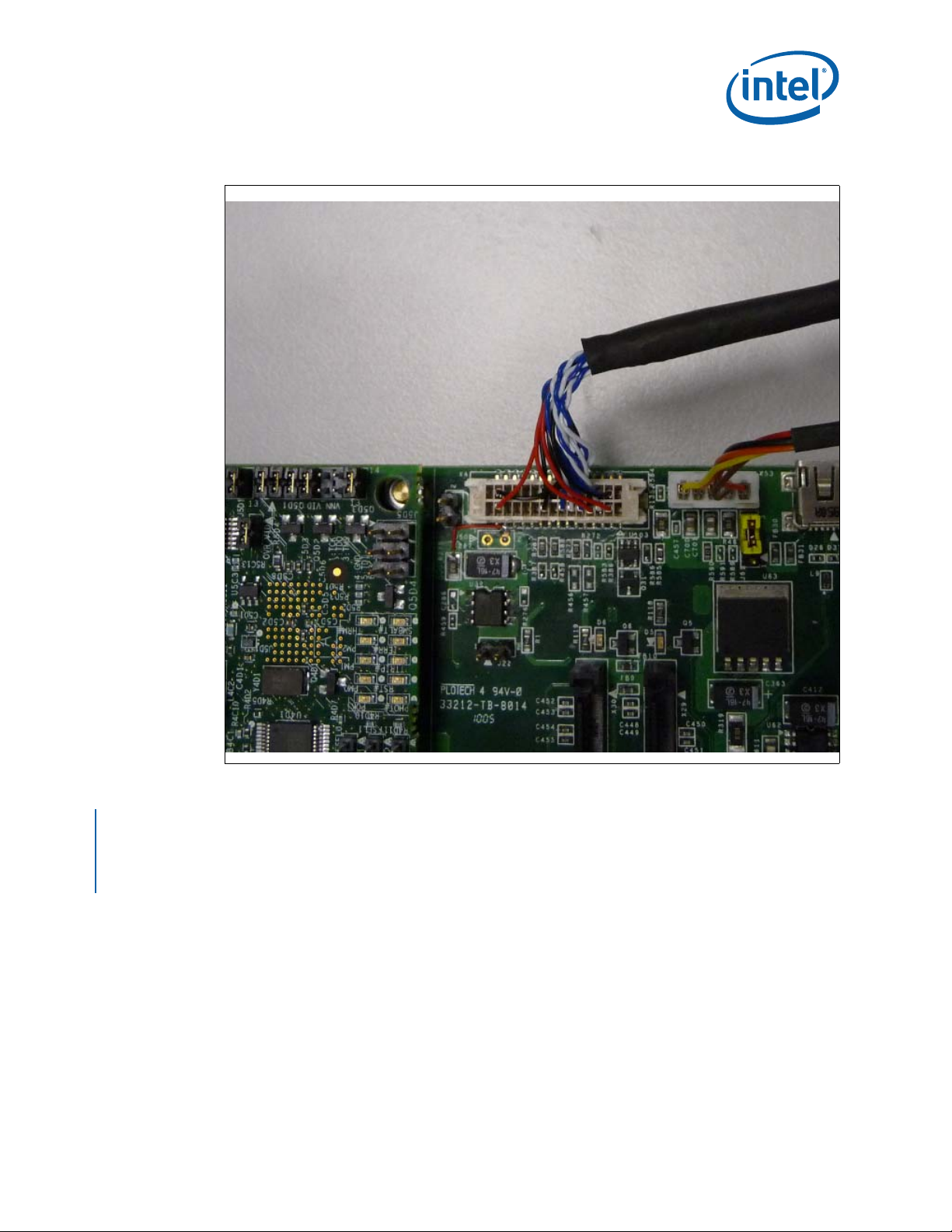
Quick Start
Figure 22. LVDS Connector and Cable
Complete the following steps to operate the reference board with the AUO 8.4 inch
(213.4 mm), 800x 600 (G084S N05 V8) panel. Th ese steps will change if us ing differen t
displays.
1. Attach the LVDS cable to the AUO panel and carrier board as shown in Figure 20,
Figure 21 and Figure 22.
2. Attach the addi tional +12V built on to the LVDS cable for LED backlight to onboard
12V supply at X53.
January 2012 User Manual
Document Number: 324213-002 63
Intel® Atom™ Processor E660 with Intel® Platform Controller Hub EG20T Development Kit
Page 64

6.3 Heat Sink Installation
All Intel® Atom™ Processor E6xx series (except the 0.6 GHz, 2.7 W devices) require a
thermal solution. This section describes how to attach the processor heat sink included
in your development kit.
Yo u will need:
• Flat-head and Phil lips-head screwdriver
• Linen free cloth
• Isopropyl alcohol (IPA)
If you are reinstalling the heat sink after removing it, you may also need thermal
interface material (TIM).
6.3.1 C OM Express* Module and Carrier Board
Figure 23. COM Express* Module and Carrier Board
Quick Start
®
Atom™ Processor E660 with Intel® Platform Controller Hub EG20T Development Kit
Intel
User Manual January 2012
64 Document Number: 324213-002
Page 65

Quick Start
6.3.2 He at Sink Installat ion
Note: All SKU except ULP (0.6GHz, 2.7W) parts require heat sink as cooling solutions.
1. Check heat sink and back plate for any visual defects prior to assembly.
Figure 24. Heat Sink Components
2. Remove double sided tape sticker from back-plate. Attach the back plate onto the
bottom side of the PCB. Back-plate pins should be ali gned to PCB holes.
3. A gap pad and sponge is provide d wi th the heat sink assembly.
Note: Thermal grease (TIM) is only needed when heat sink has been removed and reinstalled
or when the gap pad has been damaged.
4. Attach the gap pad and sponge to the ce nter of the heat sink as s hown in
Figure 25.
Figure 25. Back Side of the Heat Sink
January 2012 User Manual
Document Number: 324213-002 65
Intel® Atom™ Processor E660 with Intel® Platform Controller Hub EG20T Development Kit
Page 66

5. Clean package top surface with a clean towel and isopropyl alcohol.
6. Gently place heat sink on top of processor with heat sink mounting holes aligning
with the pins on the back plate.
7. Insert springs onto all screws; fasten the screws diagonally, following the similar
sequence as shown in Figure 26.
Caution: Do not apply external downward pressure onto heat sink during installation.
Figure 26. Sequence to Fasten the Screws
Quick Start
6.4 Power On
Complete the following steps to ope rate the reference board:
1. Install or verify the configuration jumpers as shown in Section 4.3.1.
2. Verify the presence of an RTC battery at X13.
3. Plug in an ATX power supply into connector X1. The connector is keyed and will
only fit in one position.
4. Connect a SATA hard drive to onboard SATA receptacle X29 or X30 (see Figure 12)
and ATX power to hard drive via a SATA power cable.
5. Connect a PS/2 keyboard to connector X15 (bot tom) (shown in Figure 12).
6. Connect a PS/2 mouse to connector X14 (top) (shown in Figure 12).
7. Follow steps in Section 6.2 to complete the display assembly. If an alternative to
the integrated graphics is desired, plug a PCIe* x1 Graphics card in the PCIe* slot.
Note: If PCIe* Slot X10 is used , make sure SW4-1 is ON to connect PCIe * Port 3 link to PCIe*
6.4.1 P ower Up
Slot X10 and disable Mini PCIe* Slot (X8). Refer to Figure 3 and Section 4.6 for more
details.
1. Ensure power supply is plugged in and press t he pow er button located at SW5.
2. As the system boots, press F2 or the Delete button on the keyboard to ent er the
BIOS setup screen.
3. Check time, date and configuration settings. For most users the default setting
should be sufficient for the init ia l bring-up.
4. Press F10 to save and quit the BIOS setup.
®
Atom™ Processor E660 with Intel® Platform Controller Hub EG20T Development Kit
Intel
User Manual January 2012
66 Document Number: 324213-002
Page 67

Quick Start
5. The system reboots and is ready for use.
Note: If the board do es not p ower up complete ly, the port 80 code on the 7-se gment display s
(D9 and D10) m ay p ro vi de i nsi ght i n to th e is su e. Refer to Section 5.3.4 for more detail.
6.4.2 Power Down
1. Use OS control led shutdown mechanism (Windows Start menu or equivalent).
2. If the system is hung, it is possible to asynchronously shut the system down by
holding the power butto n (SW5) down continuously for at le ast 3 seconds.
Note: Intel does not recommend powering down the board by shutting off power at the ATX
power supply.
§ §
January 2012 User Manual
Document Number: 324213-002 67
Intel® Atom™ Processor E660 with Intel® Platform Controller Hub EG20T Development Kit
 Loading...