

Page 1

R
Intel® 955X Express Chipset
Thermal/Mechanical Design Guide
– For the Intel® 82955X Memory Controller Hub (MCH)
April 2005
Document Number: 307012-001
Page 2

R
INFORMATION IN THIS DOCUMENT IS PROVIDED IN CONNECTION WITH INTEL® PRODUCTS. NO LICENSE, EXPRESS OR IMPLIED, BY
ESTOPPEL OR OTHERWISE, TO ANY INTELLECTUAL PROPERTY RIGHTS IS GRANTED BY THIS DOCUMENT. EXCEPT AS PROVIDED IN
INTEL’S TERMS AND CONDITIONS OF SALE FOR SUCH PRODUCTS, INTEL ASSUMES NO LIABILITY WHATSOEVER, AND INTEL
DISCLAIMS ANY EXPRESS OR IMPLIED WARRANTY, RELATING TO SALE AND/OR USE OF INTEL PRODUCTS INCLUDING LIABILITY OR
WARRANTIES RELATING TO FITNESS FOR A PARTICULAR PURPOSE, MERCHANTABILITY, OR INFRINGEMENT OF ANY PATENT,
COPYRIGHT OR OTHER INTELLECTUAL PROPERTY RIGHT. Intel products are not intended for use in medical, life saving, or life sustaining
applications.
Intel may make changes to specifications and product descriptions at any time, without notice.
Designers must not rely on the absence or characteristics of any features or instructions marked "reserved" or "undefined." Intel reserves these for
future definition and shall have no responsibility whatsoever for conflicts or incompatibilities arising from future changes to them.
®
The Intel
from published specifications. Current characterized errata are available on request.
Contact your local Intel sales office or your distributor to obtain the latest specifications and before placing your product order.
∆
different processor families. See www.intel.com/products/processor_number
Intel, Pentium and the Intel logo are trademarks or registered trademarks of Intel Corporation or its subsidiaries in the United States and other
countries.
*Other names and brands may be claimed as the property of others.
Copyright © 2005, Intel Corporation
82955X Memory Controller Hub (MCH) may contain design defects or errors known as errata which may cause the product to deviate
Intel processor numbers are not a measure of performance. Processor numbers differentiate features within each processor family, not across
for details.
2 Intel
®
955X Express Chipset Thermal/Mechanical Design Guide
Page 3

R
Contents
Introduction .........................................................................................................................7
1
1.1 Definition of Terms .................................................................................................8
1.2 Reference Documents............................................................................................8
2 Packaging Technology........................................................................................................9
2.1 Package Mechanical Requirements.....................................................................10
3 Thermal Specifications......................................................................................................11
3.1 Thermal Design Power (TDP)..............................................................................11
3.2 Die Case Temperature Specifications..................................................................11
4 Thermal Simulation...........................................................................................................13
5 Thermal Metrology............................................................................................................15
5.1 Die Case Temperature Measurements................................................................15
5.1.1 Zero Degree Angle Attach Methodology ..............................................15
6 Reference Thermal Solution.............................................................................................17
6.1 Operating Environment ........................................................................................17
6.2 Heatsink Performance..........................................................................................17
6.3 Mechanical Design Envelope...............................................................................18
6.4 Board-Level Components Keep-out Dimensions.................................................20
6.5 Reference Heatsink Thermal Solution Assembly.................................................21
6.5.1 Heatsink Orientation .............................................................................22
6.5.2 Extruded Heatsink Profiles ...................................................................22
6.5.3 Mechanical Interface Material...............................................................23
6.5.4 Thermal Interface Material....................................................................23
6.5.4.1 Effect of Pressure on TIM Performance..............................24
6.5.5 Heatsink Clip.........................................................................................24
6.5.6 Clip Retention Anchors.........................................................................24
6.6 Reliability Guidelines............................................................................................25
7 Appendix A: Thermal Solution Component Suppliers.......................................................27
8 Appendix B: Mechanical Drawings ...................................................................................29
®
Intel
955X Express Chipset Thermal/Mechanical Design Guide 3
Page 4

Figures
Figure 2-1. MCH Package Dimensions (Top View)............................................................9
Figure 2-2. MCH Package Dimensions (Side View)...........................................................9
Figure 2-3. MCH Package Dimensions (Bottom View).....................................................10
Figure 5-1. Thermal Solution Decision Flowchart.............................................................16
Figure 5-2. Zero Degree Angle Attach Methodology........................................................16
Figure 5-3. Zero Degree Angle Attach Methodology (Top View)......................................16
Figure 6-1. Reference Heatsink Measured Thermal Performance versus Approach
Velocity ......................................................................................................................18
Figure 6-2. Heatsink Volumetric Envelope for the MCH...................................................19
Figure 6-3. MCH Heatsink Board Component Keep-out..................................................20
Figure 6-4. Retention Mechanism Component Keep-out Zones......................................21
Figure 6-5. Plastic Wave Soldering Heatsink Assembly...................................................22
Figure 6-6. Plastic Wave Soldering Heatsink Extrusion Profile........................................23
Figure 8-1. Plastic Wave Soldering Heatsink Assembly Drawing ....................................30
Figure 8-2. Plastic Wave Soldering Heatsink Drawing (1 of 2)........................................31
Figure 8-3. Plastic Wave Soldering Heatsink Drawing (2 of 2)........................................32
Figure 8-4. Plastic Wave Soldering Heatsink Ramp Clip Drawing (1 of 2).......................33
Figure 8-5. Plastic Wave Soldering Heatsink Ramp Clip Drawing (2 of 2).......................34
Figure 8-6. Plastic Wave Soldering Heatsink Wire Clip Drawing .....................................35
Figure 8-7. Plastic Wave Soldering Heatsink Solder-Down Anchor Drawing ..................36
R
Tables
Table 3-1. MCH Thermal Specifications...........................................................................11
Table 6-1 Honeywell PCM 45F TIM Performance as a Function of Attach Pressure ......24
Table 6-2. Reliability Guidelines .......................................................................................25
Table 7-1. MCH Heatsink Thermal Solution.....................................................................27
Table 8-1. Mechanical Drawing List..................................................................................29
4 Intel
®
955X Express Chipset Thermal/Mechanical Design Guide
Page 5

R
Revision History
Revision
Number
-001 • Initial Release. April 2005
Description Revision Date
§
®
Intel
955X Express Chipset Thermal/Mechanical Design Guide 5
Page 6

R
6 Intel
®
955X Express Chipset Thermal/Mechanical Design Guide
Page 7

Introduction
R
1 Introduction
As the complexity of computer systems increases, so do the power dissipation requirements. Care
must be taken to ensure that the additional power is properly dissipated. Typical methods to
improve heat dissipation include selective use of ducting, and/or passive heatsinks.
The goals of this document are to:
®
• Outline the thermal and mechanical operating limits and specifications for the Intel
Express Chipset Memory Controller Hub (MCH).
• Describe a reference thermal solution that meets the specification of the 82955X MCH.
Properly designed thermal solutions provide adequate cooling to maintain the MCH die
temperatures at or below thermal specifications. This is accomplished by providing a low localambient temperature, ensuring adequate local airflow, and minimizing the die to local-ambient
thermal resistance. By maintaining the MCH die temperature at or below the specified limits, a
system designer can ensure the proper functionality, performance, and reliability of the chipset.
Operation outside the functional limits can degrade system performance and may cause
permanent changes in the operating characteristics of the component.
82955X
The simplest and most cost effective method to improve the inherent system cooling
characteristics is through careful design and placement of fans, vents, and ducts. When additional
cooling is required, component thermal solutions may be implemented in conjunction with system
thermal solutions. The size of the fan or heatsink can be varied to balance size and space
constraints with acoustic noise.
This document addresses thermal design and specifications for the 82955X MCH component
only. For thermal design information on other chipset components, refer to the respective
component datasheet. For the ICH7, refer to the Intel
®
I/O Controller Hub 7 (ICH7) Thermal
Design Guidelines.
Note: Unless otherwise specified, the term MCH refers to the Intel
®
82955X Express chipset MCH.
®
Intel
955X Express Chipset Thermal/Mechanical Design Guide 7
Page 8
Introduction
1.1 Definition of Terms
Term Description
BGA Ball grid array. A package type, defined by a resin-fiber substrate, onto which a die is
mounted, bonded and encapsulated in molding compound. The primary electrical interface is
an array of solder balls attached to the substrate opposite the die and molding compound.
BLT Bond line thickness. Final settled thickness of the thermal interface material after installation
of heatsink.
ICH7 I/O Controller Hub. Seventh generation I/O Controller Hub component that contains
additional functionality compared to previous ICH components. The I/O Controller Hub
component that contains the primary PCI interface, LPC interface, USB2, ATA-100, and
other I/O functions. It communicates with the MCH over a proprietary interconnect called
DMI.
MCH Memory Controller Hub. The chipset component that contains the processor interface, the
memory interface, and the DMI.
T
case_max
T
case_min
TDP Thermal design power. Thermal solutions should be designed to dissipate this target power
Maximum die temperature allowed. This temperature is measured at the geometric center of
the top of the package die.
Minimum die temperature allowed. This temperature is measured at the geometric center of
the top of the package die.
level. TDP is not the maximum power that the chipset can dissipate.
R
1.2 Reference Documents
The reader of this specification should also be familiar with material and concepts presented in
the following documents:
Document Title Document Number / Location
Intel® I/O Controller Hub 7 (ICH7) Thermal Design Guidelines http://developer.intel.com//desi
Intel® I/O Controller Hub 7 (ICH7) Datasheet http://developer.intel.com//design/c
Intel® 955X Express Chipset Datasheet http://developer.intel.com/design/c
BGA/OLGA Assembly Development Guide Contact your Intel Field Sales
Various system thermal design suggestions http://www.formfactors.org
§
gn/chipsets/designex/307015.htm
hipsets/datashts/307013.htm
hipsets/datashts/306828.htm
Representative
8 Intel
®
955X Express Chipset Thermal/Mechanical Design Guide
Page 9
Packaging Technology
R
2 Packaging Technology
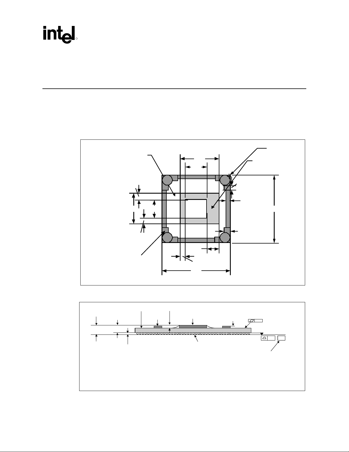
The 955X Express chipset consists of two individual components: the MCH and the ICH7. The
MCH component uses a 34 mm squared, 6-layer flip chip ball grid array (FC-BGA) package (see
Figure 2-1 through Figure 2-3). For information on the ICH7 package, refer to the Intel
Controller Hub 7 (ICH7) Thermal Design Guidelines.
Figure 2-1. MCH Package Dimensions (Top View)
®
I/O
Capaci tor Area,
Handling Exclusion
Zone
3.1
15.34 9.14
3.1
Handling Area
Figure 2-2. MCH Package Dimensions (Side View)
2.355 ± 0.082 mm
Substrate
1.92 ± 0.078 mm
0.84 ± 0.05 mm
Decoup
Cap
19.38
10.67
MCH
Die
6.17
2.54
34.00
Die
0. 7 mm Max
2.30
2.0
3.0
Ø5.20mm
Die
Keepout
Area
34.00
955X_Pkg_TopView
0.20 See note 4.
0.435 ± 0.025 mm
See note 3
Notes:
1. Primary datum -C- and seating plan are defined by the spherical crow ns of the solder balls (shown before motherboard attach)
2. All dimensions and tolerances conf orm to ANSI Y14.5M-1994
3. BGA has a pre-SMT height of 0.5mm and post-SMT height of 0.41-0.46mm
4. Shown before motherboard attach; FCBGA has a convex (dome shaped) orientation before reflow and is expected to have a slightly concave (bow l
shaped) orientation after reflow
®
Intel
955X Express Chipset Thermal/Mechanical Design Guide 9
Seating Plane
0.20 –C–
See note 1.
955X_Pkg_SideView
Page 10
Packaging Technology
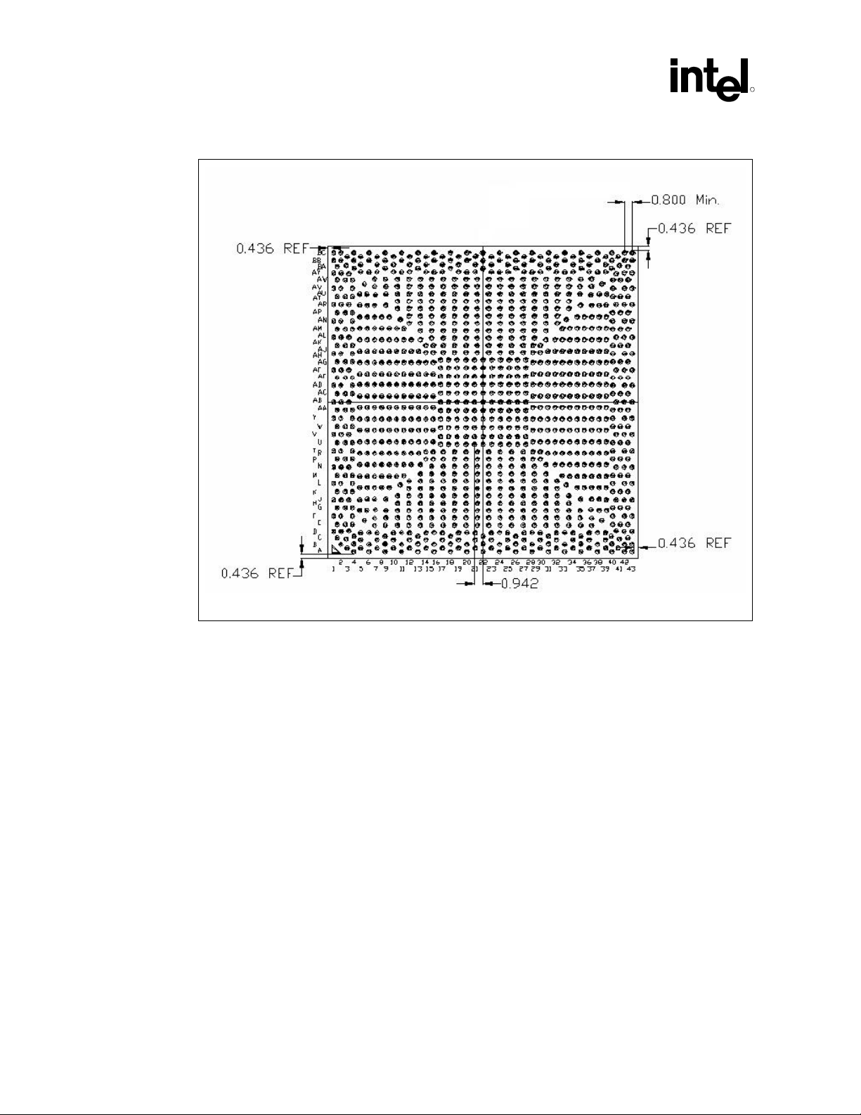
Figure 2-3. MCH Package Dimensions (Bottom View)
R
NOTES:
1. All dimensions are in millimeters.
2. All dimensions and tolerances conform to ANSI Y14.5M-1994.
2.1 Package Mechanical Requirements
The MCH package has an exposed bare die that is capable of sustaining a maximum static normal
load of 10-lbf. The package is NOT capable of sustaining a dynamic or static compressive load
applied to any edge of the bare die. These mechanical load limits must not be exceeded during
heatsink installation, mechanical stress testing, standard shipping conditions and/or any other use
condition.
Note:
1. The heatsink attach solutions must not result in continuous stress onto the chipset package
with the exception of a uniform load to maintain the heatsink-to-package thermal interface.
2. These specifications apply to uniform compressive loading in a direction perpendicular to the
bare die top surface.
3. These specifications are based on limited testing for design characterization. Loading limits
are for the package only.
§
10 Intel
®
955X Express Chipset Thermal/Mechanical Design Guide
Page 11
Thermal Specifications
R
3 Thermal Specifications
3.1 Thermal Design Power (TDP)
Analysis indicates that real applications are unlikely to cause the chipset MCH to consume
maximum power dissipation for sustained time periods. Therefore, to arrive at a more realistic
power level for thermal design purposes, Intel characterizes power consumption based on known
platform benchmark applications. The resulting power consumption is referred to as the Thermal
Design Power (TDP). TDP is the target power level that the thermal solutions should be designed
to. TDP is not the maximum power that the chipset can dissipate.
For TDP specifications, see Table 3-1 for the 955X Express chipset MCH. FC-BGA packages
have limited heat transfer capability into the board and have minimal thermal capability without a
thermal solution. Intel recommends that system designers plan for one or more heatsinks when
using the 955X Express chipset.
3.2 Die Case Temperature Specifications
To ensure proper operation and reliability of the MCH, the die temperatures must be at or
between the maximum/minimum operating range as specified in Table 3-1 for the 82955X MCH.
System and/or component level thermal solutions are required to maintain these temperature
specifications. Refer to Chapter 5 for guidelines on accurately measuring package die
temperatures.
Table 3-1. MCH Thermal Specifications
Parameter Value Notes
T
105 °C —
case_max
T
5 °C —
case_min
TDP
NOTE: These specifications are based on silicon characterization; however, they may be updated as further
data becomes available.
13.5 W DDR2-667
dual channel
§
®
Intel
955X Express Chipset Thermal/Mechanical Design Guide 11
Page 12

Thermal Specifications
R
12 Intel
®
955X Express Chipset Thermal/Mechanical Design Guide
Page 13

Thermal Simulation
R
4 Thermal Simulation
Intel provides thermal simulation models of the 955X Express chipset MCH and associated user's
guides to aid system designers in simulating, analyzing, and optimizing their thermal solutions in
an integrated, system-level environment. The models are for use with the commercially available
Computational Fluid Dynamics (CFD)-based thermal analysis tool “FLOTHERM”* (version 5.1
or higher) by Flomerics, Inc. Contact your Intel field sales representative to order the thermal
models and user's guides.
§
®
Intel
955X Express Chipset Thermal/Mechanical Design Guide 13
Page 14

Thermal Simulation
R
14 Intel
®
955X Express Chipset Thermal/Mechanical Design Guide
Page 15

Thermal Metrology
R
5 Thermal Metrology
The system designer must make temperature measurements to accurately determine the thermal
performance of the system. Intel has established guidelines for proper techniques to measure the
MCH die temperatures. Section 5.1 provides guidelines on how to accurately measure the MCH
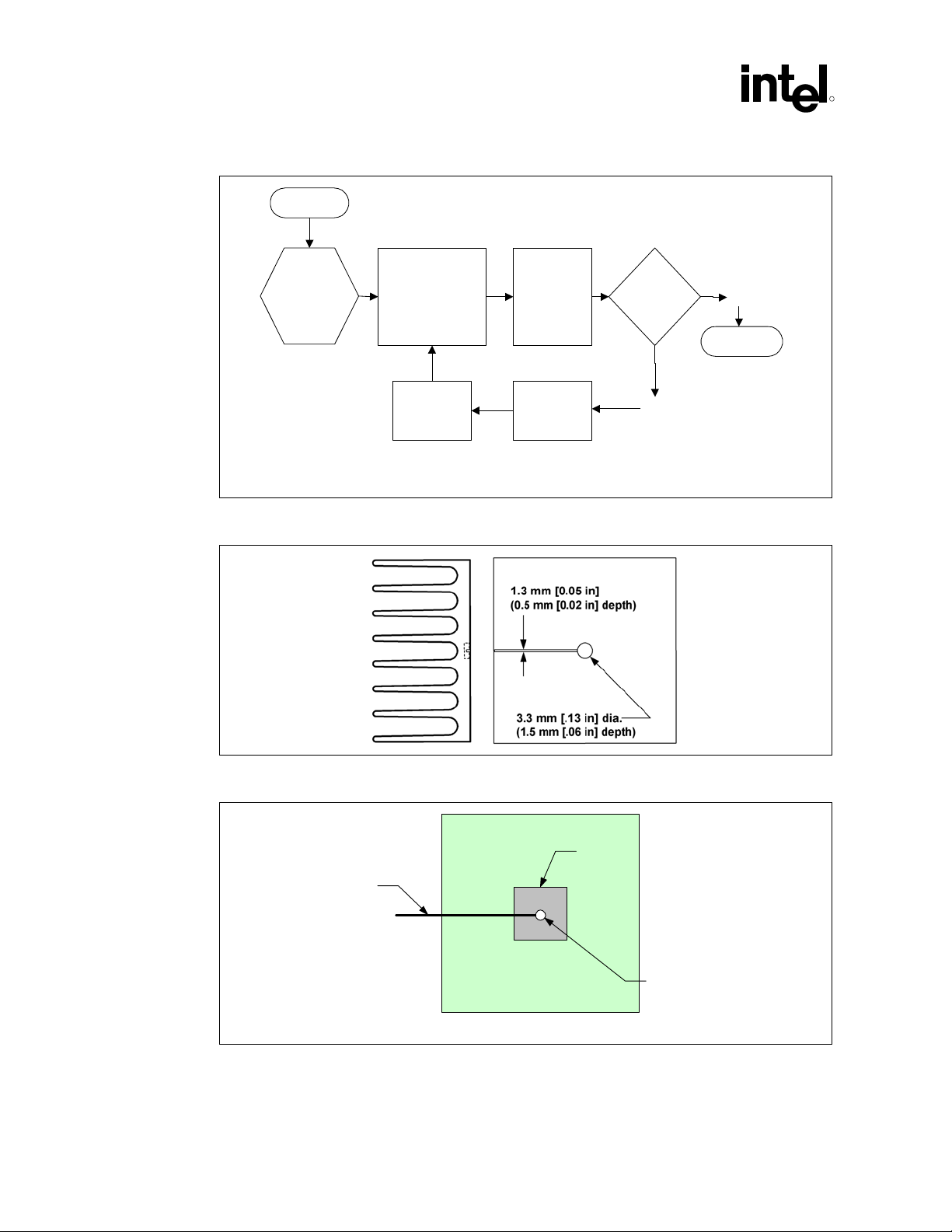
die temperatures. The flowchart in Figure 5-1 offers useful guidelines for thermal performance
and evaluation.
5.1 Die Case Temperature Measurements
To ensure functionality and reliability, the T
maximum/minimum operating range of the temperature specification as noted in Table 3-1. . The
surface temperature at the geometric center of the die corresponds to T
requires special care to ensure an accurate temperature measurement.
Temperature differences between the temperature of a surface and the surrounding local ambient
air can introduce errors in the measurements. The measurement errors could be due to a poor
thermal contact between the thermocouple junction and the surface of the package, heat loss by
radiation and/or convection, conduction through thermocouple leads, and/or contact between the
thermocouple cement and the heatsink base (if a heatsink is used). For maximum measurement
accuracy, only the 0° thermocouple attach approach is recommended.
of the MCH must be maintained at or between the
case
5.1.1 Zero Degree Angle Attach Methodology
1. Mill a 3.3 mm (0.13 in.) diameter and 1.5 mm (0.06 in.) deep hole centered on the bottom of
the heatsink base.
2. Mill a 1.3 mm (0.05 in.) wide and 0.5 mm (0.02 in.) deep slot from the centered hole to one
edge of the heatsink. The slot should be parallel to the heatsink fins (see Figure 5-2).
3. Attach thermal interface material (TIM) to the bottom of the heatsink base.
4. Cut out portions of the TIM to make room for the thermocouple wire and bead. The cutouts
should match the slot and hole milled into the heatsink base.
5. Attach a 36 gauge or smaller calibrated K-type thermocouple bead or junction to the center of
the top surface of the die using a high thermal conductivity cement. During this step, ensure
no contact is present between the thermocouple cement and the heatsink base because any
contact will affect the thermocouple reading. It is critical that the thermocouple bead
makes contact with the die (see Figure 5-3).
6. Attach heatsink assembly to the MCH and route thermocouple wires out through the milled
slot.
. Measuring T
case
case
®
Intel
955X Express Chipset Thermal/Mechanical Design Guide 15
Page 16
Thermal Metrology
Figure 5-1. Thermal Solution Decision Flowchart
Start
R
Attach
Attach device
to board using
normal reflow
process.
thermocouples using
recommended
metrology. Se tu p the
system in the desir ed
configuration.
Select Heatsink
Figure 5-2. Zero Degree Angle Attach Methodology
Run the Power
program and
monitor the
device die
temperature.
Heatsink
Required
Tdie >
Specification?
Yes
No
End
Therm_Solution_Flow
Figure 5-3. Zero Degree Angle Attach Methodology (Top View)
Thermocouple
NOTE: Not to scale.
Wire
Substrate
§
16 Intel
®
955X Express Chipset Thermal/Mechanical Design Guide
Die
Cement +
Thermocouple Bead
0_Angle_Attach_Method
Page 17

Reference Thermal Solution
R
6 Reference Thermal Solution
Intel has developed a reference thermal solution designed to meet the cooling needs of the MCH
under operating environments and specifications defined in this document. This chapter describes
the overall requirements for the Plastic Wave Soldering Heatsink (PWSH) reference thermal
solution including critical-to-function dimensions, operating environment, and validation criteria.
Other chipset components may or may not need attached thermal solutions, depending on your
specific system local-ambient operating conditions. For information on the ICH7, refer to thermal
specification in the Intel
6.1 Operating Environment
The reference thermal solution was designed assuming a maximum local-ambient temperature of
55 °C. The minimum recommended airflow velocity through the cross section of the heatsink fins
is 350 linear feet per minute (lfm). The approaching airflow temperature is assumed to be equal to
the local-ambient temperature. The thermal designer must carefully select the location to measure
airflow to obtain an accurate estimate. These local-ambient conditions are based on a 35 °C
external-ambient temperature at sea level. (External-ambient refers to the environment external to
the system.)
®
I/O Controller Hub 7 (ICH7) Thermal Design Guidelines.
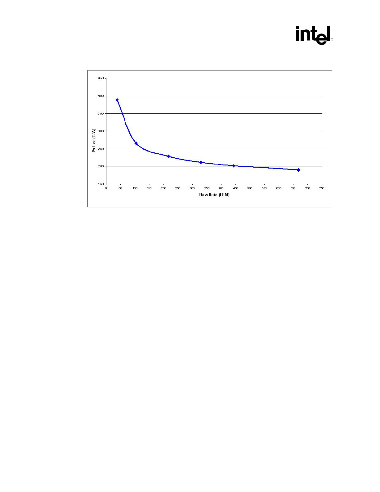
6.2 Heatsink Performance
Figure 6-1 depicts the measured thermal performance of the reference thermal solution versus
approach air velocity. Since this data was measured at sea level, a correction factor would be
required to estimate thermal performance at other altitudes.
®
Intel
955X Express Chipset Thermal/Mechanical Design Guide 17
Page 18
Reference Thermal Solution
Figure 6-1. Reference Heatsink Measured Thermal Performance versus Approach Velocity
R
6.3 Mechanical Design Envelope
While each design may have unique mechanical volume and height restrictions or implementation
requirements, the height, width, and depth constraints typically placed on the MCH thermal
solution are shown in Figure 6-2.
When using heatsinks that extend beyond the MCH reference heatsink envelope shown in
Figure 6-2, any motherboard components placed between the heatsink and motherboard cannot
exceed 2.2 mm (0.087 in.) in height.
18 Intel
®
955X Express Chipset Thermal/Mechanical Design Guide
Page 19

Reference Thermal Solution
R
Figure 6-2. Heatsink Volumetric Envelope for the MCH
Ramp
FCBGA + Solder
Balls
Retainer
Heatsink Fin
Heatsink Base
TIM
Die
Motherboard
60.6 mm
48.0 mm
26.79 mm
2.50 mm
33.50 mm
1.90 mm
81.0 mm
67.0 mm
45.79 mm
TNB
Heatsink Fin
O
135
47.0 mm
60.92 mm
Max 2.2 mm
Component
Height
No
component
this Area
HS_Vol_Envelope_MCH
®
Intel
955X Express Chipset Thermal/Mechanical Design Guide 19
Page 20

Reference Thermal Solution
6.4 Board-Level Components Keep-out Dimensions
The location of hole patterns and keep-out zones for the reference thermal solution are shown in
Figure 6-3 and Figure 6-4.
Figure 6-3. MCH Heatsink Board Component Keep-out
60.6 mm
48.0 mm
26.79 mm
TNB
R
81.0 mm
67.0 mm
45.79 mm
Heatsink Fin
O
135
47.0 mm
Air Flow
60.92 mm
HS_Brd_Component_Keepout
Max 2.2 mm
Component
Height
No
component
this Area
20 Intel
®
955X Express Chipset Thermal/Mechanical Design Guide
Page 21

Reference Thermal Solution
R
Figure 6-4. Retention Mechanism Component Keep-out Zones
4 x 8.76 mm
Max 1.27mm
Component
Height
4 x 5.08mm
4 x 1.84mm
8 x Ø0.97 mm Plated Thru Hole
8 x Ø1.42 mm Trace Keepout
RM_Component_KeepoutZones
4 x 8.76mm
No Components
this Area
6.5 Reference Heatsink Thermal Solution Assembly
The reference thermal solution for the MCH is a passive extruded heatsink with thermal interface.
It is attached using a clip with each end hooked through an anchor soldered to the board. Figure
6-5 shows the reference thermal solution assembly and associated components.
Full mechanical drawings of the thermal solution assembly and the heatsink clip are provided in
Appendix B. Appendix A contains vendor information for each thermal solution component.
®
Intel
955X Express Chipset Thermal/Mechanical Design Guide 21
Page 22

Reference Thermal Solution
Figure 6-5. Plastic Wave Soldering Heatsink Assembly
R
6.5.1 Heatsink Orientation
To enhance the efficiency of the reference thermal solution, it is important for the designer to
orient the fins properly with respect to the mean airflow direction. Simulation and experimental
evidence have shown that the MCH heatsink thermal performance is enhanced when the fins are
aligned with the mean airflow direction (see Figure 6-3).
6.5.2 Extruded Heatsink Profiles
The reference thermal solution uses an extruded heatsink for cooling the MCH. Figure 6-5 shows
the heatsink profile. Appendix A lists a supplier for this extruded heatsink. Other heatsinks with
similar dimensions and increased thermal performance may be available. Full mechanical drawing
of this heatsink is provided in Appendix B.
22 Intel
®
955X Express Chipset Thermal/Mechanical Design Guide
Page 23

Reference Thermal Solution
R
Figure 6-6. Plastic Wave Soldering Heatsink Extrusion Profile
NOTE: All dimensions are in millimeters, with dimensions in braces expressed in inches.
6.5.3 Mechanical Interface Material
There is no mechanical interface material associated with this reference solution.
6.5.4 Thermal Interface Material
A TIM provides improved conductivity between the die and heatsink. The reference thermal
solution uses Honeywell PCM 45F, 0.25 mm (0.010 in.) thick, 15 mm x 15 mm
(0.59 in. x 0.59 in.) square.
Note: Unflowed or “dry” Honeywell PCM 45F has a material thickness of 0.010 inch. The flowed or
“wet” Honeywell PCM 45F has a material thickness of ~0.003 inches after it reaches its phase
change temperature.
®
Intel
955X Express Chipset Thermal/Mechanical Design Guide 23
Page 24

Reference Thermal Solution
6.5.4.1 Effect of Pressure on TIM Performance
As mechanical pressure increases on the TIM, the thermal resistance of the TIM decreases. This
phenomenon is due to the decrease of the bond line thickness (BLT). BLT is the final settled
thickness of the thermal interface material after installation of heatsink. The effect of pressure on
the thermal resistance of the Honeywell* PCM45F TIM is shown in Table 6-1. The heatsink clip
provides enough pressure for the TIM to achieve a thermal conductivity of 0.17 °C inch
Table 6-1 Honeywell PCM 45F TIM Performance as a Function of Attach Pressure
Pressure (psi) Thermal Resistance (°C × in2)/W
5 0.049
10 0.046
20 0.045
30 0.044
2
/W.
R
Note: All measured at 50 °C.
6.5.5 Heatsink Clip
The retention mechanism in this reference solution includes two different types of clips; one is
ramp clip and the other is wire clip. Each end of the wire clip is attached to the ramp clip that in
turn attaches to anchors to fasten the overall heatsink assembly to the motherboard. See
Appendix B for a mechanical drawing of the clip.
6.5.6 Clip Retention Anchors
For 955X Express chipset-based platforms that have very limited board space, a clip retention
anchor has been developed to minimize the impact of clip retention on the board. It is based on a
standard two-pin jumper and is soldered to the board like any common through-hole header. A
new anchor design is available with 45° bent leads to increase the anchor attach reliability over
time. See Appendix A for the part number and supplier information.
24 Intel
®
955X Express Chipset Thermal/Mechanical Design Guide
Page 25

Reference Thermal Solution
R
6.6 Reliability Guidelines
Each motherboard, heatsink and attach combination may vary the mechanical loading of the
component. Based on the end user environment, the user should define the appropriate reliability
test criteria and carefully evaluate the completed assembly prior to use in high volume. Some
general recommendations are shown in Table 6-2.
Table 6-2. Reliability Guidelines
Test1 Requirement Pass/Fail Criteria2
Mechanical Shock 50 g, board level, 11 msec, 3 shocks/axis. Visual Check and Electrical
Functional Test
Random Vibration 7.3 g, board level, 45 min/axis, 50 Hz to 2000 Hz. Visual Check and Electrical
Functional Test
Temperature Life 85°C, 2000 hours total, checkpoints at 168, 500,
1000, and 2000 hours.
Thermal Cycling –5 °C to +70 °C, 500 cycles. Visual Check
Humidity 85% relative humidity, 55 °C, 1000 hours. Visual Check
Visual Check
NOTES:
1. It is recommended that the above tests be performed on a sample size of at least twelve assemblies
from three lots of material.
2. Additional pass/fail criteria may be added at the discretion of the user.
§
®
Intel
955X Express Chipset Thermal/Mechanical Design Guide 25
Page 26

Reference Thermal Solution
R
26 Intel
®
955X Express Chipset Thermal/Mechanical Design Guide
Page 27

Appendix A: Thermal Solution Component Suppliers
R
7 Appendix A: Thermal Solution
Component Suppliers
This list is provided by Intel solely as a convenience to customers. Intel has not tested, designed
or validated these products and does not warrant user suitability or performance in any way.
Customers are solely responsible for determining the suitability and application of these products
for their designs.
Table 7-1. MCH Heatsink Thermal Solution
Part
Heatsink Assembly
includes:
⎯ Pin-Fin Heatsink
⎯ Thermal Interface
Material
⎯ Ramp Clip
⎯ Wire Clip
Pin-Fin Heatsink
Thermal Interface
(PCM 45F)
Heatsink Ramp Clip
Heatsink Wire Clip
Intel Part
Number
C99237-001 CCI
C92139-001 CCI
C34795-001
C92140-001 CCI
C85373-001 CCI
Supplier
(Part Number)
Honeywell
PCM 45F
Contact Information
Monica Chih (Taiwan)
866-2-29952666, x131
monica_chih@ccic.com.tw
Harry Lin (CCI/ACK-USA)
714-739-5797
hlinack@aol.com
Monica Chih (Taiwan)
866-2-29952666, x131
monica_chih@ccic.com.tw
Harry Lin (CCI/ACK-USA)
714-739-5797
hlinack@aol.com
Scott Miller
509-252-2206
scott.miller4@honeywell.com
Monica Chih (Taiwan)
866-2-29952666, x131
monica_chih@ccic.com.tw
Harry Lin (CCI/ACK-USA)
714-739-5797
hlinack@aol.com
Monica Chih (Taiwan)
866-2-29952666, x131
monica_chih@ccic.com.tw
Harry Lin (CCI/ACK-USA)
714-739-5797
hlinack@aol.com
®
Intel
955X Express Chipset Thermal/Mechanical Design Guide 27
Page 28

Appendix A: Thermal Solution Component Suppliers
R
Part
Solder-Down Anchor
NOTE: The enabled components may not be currently available from all suppliers. Contact the supplier directly
to verify time of component availability.
Intel Part
Number
C85376-001 Wieson
Supplier
(Part Number)
Contact Information
Rick Lin
Deputy Manager/Project Sales
Department
Add.: 7F, No. 276, Section 1, Tatung
Road, Hsichih City, Taipei Hsien, Taiwan
Tel: 886-2-2647-1896 ext. 6342
Mobile: 886-955644008
Email: rick@wieson.com
Website: www. wieson.com
§
28 Intel
®
955X Express Chipset Thermal/Mechanical Design Guide
Page 29

Appendix B: Mechanical Drawings
R
8 Appendix B: Mechanical Drawings
Table 8-1 lists the mechanical drawings included in this appendix.
Table 8-1. Mechanical Drawing List
Drawing Description Figure Number
Plastic Wave Soldering Heatsink Assembly Drawing Figure 8-1
Plastic Wave Soldering Heatsink Drawing (1 of 2) Figure 8-2
Plastic Wave Soldering Heatsink Drawing (2 of 2) Figure 8-3
Plastic Wave Soldering Heatsink Ramp Clip Drawing (1 of 2) Figure 8-4
Plastic Wave Soldering Heatsink Ramp Clip Drawing (2 of 2) Figure 8-5
Plastic Wave Soldering Heatsink Wire Clip Drawing Figure 8-6
Plastic Wave Soldering Heatsink Solder-Down Anchor Drawing Figure 8-7
®
Intel
955X Express Chipset Thermal/Mechanical Design Guide 29
Page 30

Appendix B: Mechanical Drawings
Figure 8-1. Plastic Wave Soldering Heatsink Assembly Drawing
R
30 Intel
®
955X Express Chipset Thermal/Mechanical Design Guide
Page 31
Appendix B: Mechanical Drawings
R
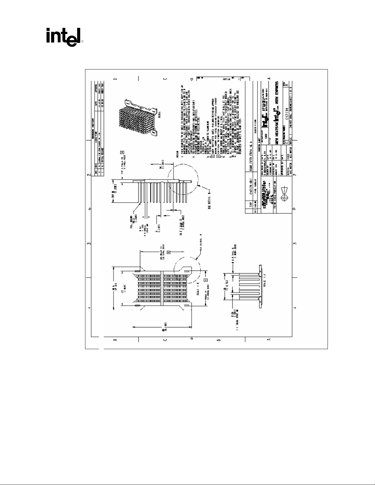
Figure 8-2. Plastic Wave Soldering Heatsink Drawing (1 of 2)
®
Intel
955X Express Chipset Thermal/Mechanical Design Guide 31
Page 32

Appendix B: Mechanical Drawings
Figure 8-3. Plastic Wave Soldering Heatsink Drawing (2 of 2)
R
32 Intel
®
955X Express Chipset Thermal/Mechanical Design Guide
Page 33

Appendix B: Mechanical Drawings
R
Figure 8-4. Plastic Wave Soldering Heatsink Ramp Clip Drawing (1 of 2)
®
Intel
955X Express Chipset Thermal/Mechanical Design Guide 33
Page 34

Appendix B: Mechanical Drawings
Figure 8-5. Plastic Wave Soldering Heatsink Ramp Clip Drawing (2 of 2)
R
34 Intel
®
955X Express Chipset Thermal/Mechanical Design Guide
Page 35

Appendix B: Mechanical Drawings
R
Figure 8-6. Plastic Wave Soldering Heatsink Wire Clip Drawing
®
Intel
955X Express Chipset Thermal/Mechanical Design Guide 35
Page 36

Appendix B: Mechanical Drawings
Figure 8-7. Plastic Wave Soldering Heatsink Solder-Down Anchor Drawing
R
§
36 Intel
®
955X Express Chipset Thermal/Mechanical Design Guide
 Loading...