

Page 1

Intel® 945G/945GZ/945GC/
945P/945PL Express Chipset
Family
Thermal and Mechanical Design Guidelines (TMDG)
- For the Intel® 82945G/82945GZ/82945GC Graphics Memory
Controller Hub (GMCH) and Intel® 82945P/82945PL Memory
Controller Hub (MCH)
February 2008
Document Number: 307504-004
Page 2

INFORMATION IN THIS DOCUMENT IS PROVIDED IN CONNECTION WITH INTEL® PRODUCTS. NO LICENSE, EXPRESS OR
IMPLIED, BY ESTOPPEL OR OTHERWISE, TO ANY INTELLECTUAL PROPERTY RIGHTS IS GRANTED BY THIS DOCUMENT. EXCEPT
AS PROVIDED IN INTEL'S TERMS AND CONDITIONS OF SALE FOR SUCH PRODUCTS, INTEL ASSUMES NO LIABILITY
WHATSOEVER, AND INTEL DISCLAIMS ANY EXPRESS OR IMPLIED WARRANTY, RELATING TO SALE AND/OR USE OF INTEL
PRODUCTS INCLUDING LIABILITY OR WARRANTIES RELATING TO FITNESS FOR A PARTICULAR PURPOSE, MERCHANTABILITY,
OR INFRINGEMENT OF ANY PATENT, COPYRIGHT OR OTHER INTELLECTUAL PROPERTY RIGHT.
UNLESS OTHERWISE AGREED IN WRITING BY INTEL, THE INTEL PRODUCTS ARE NOT DESIGNED NOR INTENDED FOR ANY
APPLICATION IN WHICH THE FAILURE OF THE INTEL PRODUCT COULD CREATE A SITUATION WHERE PERSONAL INJURY OR
DEATH MAY OCCUR.
Intel may make changes to specifications and product descriptions at any time, without notice.
Designers must not rely on the absence or characteristics of any features or instructions marked "reserved" or "undefined." Intel
reserves these for future definition and shall ha ve no responsibility whatsoever for conflicts or incompatibilities arising from
future changes to them.
The Intel
errata, which may cause the product to deviate from published specifications. Current characterized errata are available on
request.
Contact your local Intel sales office or your distributor to obtain the latest specifications and before placing your product order.
Intel, Pentium, and the Intel log o are trademarks of Intel Corporation in the U.S. and other countries.
*Other names and brands may be claimed as the property of others.
Copyright © 2005–2008, Intel Corporation. All rights reserved.
®
82945G/82945GZ/82945GC GMCH and Intel® 82945P/82945PL MCH may contain design defects or errors known as
2 Thermal and Mechanical Design Guidelines
Page 3

Contents
1 Introduction.....................................................................................................7
1.1 Terminology ..........................................................................................8
1.2 Reference Documents .............................................................................9
2 Product Specifications......................................................................................11
2.1 Package Description..............................................................................11
2.1.1 Non-Grid Array Package Ball Placement......................................11
2.2 Package Loading Specifications...............................................................12
2.3 Thermal Specifications ..........................................................................13
2.4 Thermal Design Power (TDP)..................................................................13
2.4.1 Methodology...........................................................................14
2.4.2 Application Power....................................................................14
2.4.3 Specifications .........................................................................14
3 Thermal Metrology..........................................................................................15
3.1 Case Temperature Measurements...........................................................15
3.1.1 Thermocouple Attach Methodology.............................................15
3.2 Airflow Characterization ........................................................................16
4 Reference Thermal Solution..............................................................................19
4.1 Operating Environment .........................................................................19
4.1.1 ATX Form Factor Operating Environment ....................................19
4.1.2 Balanced Technology Extended (BTX) Form Factor Operating
Environment...........................................................................
4.2 Mechanical Design Envelope...................................................................21
4.3 Thermal Solution Assembly....................................................................21
4.4 Environmental Reliability Requirements...................................................24
Appendix A Enabled Suppliers ...........................................................................................25
Appendix B Mechanical Drawings.......................................................................................27
20
Thermal and Mechanical Design Guidelines 3
Page 4

Figures
Figure 1. (G)MCH Non-Grid Array......................................................................12
Figure 2. 0° Angle Attach Methodology (top view, not to scale)..............................16
Figure 3. 0° Angle Attach Heatsink Modifications (generic heatsink side and bottom
view shown, not to scale)...........................................................................
Figure 4. Airflow Temperature Measurement Locations .........................................17
Figure 5. Processor Heatsink Orientation to Provide Airflow to (G)MCH Heatsink on an
ATX Platform............................................................................................
Figure 6. Processor Heatsink Orientation to Provide Airflow to (G)MCH Heatsink on a
Balanced Technology Extended (BTX) Platform..............................................
Figure 7. ATX GMCH Heatsink Installed on Board.................................................22
Figure 8. Balanced Technology Extended (BTX) GMCH Heatsink Installed on Board...23
Figure 9. (G)MCH Package Drawing ...................................................................28
Figure 10. (G)MCH Component Keep-Out Restrictions for ATX Platforms .................29
Figure 11. (G)MCH Component Keep-Out Restrictions for Balanced Technology
Extended (BTX) Platforms ..........................................................................
Figure 12. (G)MCH Reference Heatsink for ATX Platforms – Sheet 1 .......................31
Figure 13. (G)MCH Reference Heatsink for ATX Platforms – Sheet 2 .......................32
Figure 14. (G)MCH Reference Heatsink for ATX Platforms – Anchor ........................33
Figure 15. (G)MCH Reference Heatsink for ATX Platforms – Ramp Retainer Sheet 1..34
Figure 16. (G)MCH Reference Heatsink for ATX Platforms – Ramp Retainer Sheet 2..35
Figure 17. (G)MCH Reference Heatsink for ATX Platforms – Wire Preload Clip ..........36
Figure 18. (G)MCH Reference Heatsink for Balanced Technology Extended (BTX)
Platforms.................................................................................................
Figure 19. (G)MCH Reference Heatsink for Balanced Technology Extended (BTX)
Platforms – Clip........................................................................................
Figure 20. (G)MCH Reference Heatsink for Balanced Technology Extended (BTX)
Platforms – Heatsink Assembly ...................................................................
16
20
21
30
37
38
39
Tables
Table 1. (G)MCH Loading Specifications..............................................................12
Table 2. (G)MCH Case Temperature Specifications .............................................13
Table 3. (G)MCH Thermal Design Power Specifications........................................14
Table 4. Reference Thermal Solution Environmental Reliability Requirements.........24
Table 5. (G)MCH ATX Intel Reference Heatsink Enabled Suppliers.........................25
Table 6. (G)MCH Balanced Technology Extended (BTX) Intel Reference Heatsink
Enabled Suppliers .....................................................................................
4 Thermal and Mechanical Design Guidelines
26
Page 5
Revision History
Revision
Number
-001 • Initial Release May 2005
-002 • Added Intel® 82945PL specifications October 2005
-003 • Added Intel® 82945GZ specifications December
-004 • Added Intel® 82945GC specifications February 2008
Description Date
2005
§
Thermal and Mechanical Design Guidelines 5
Page 6

6 Thermal and Mechanical Design Guidelines
Page 7

Introduction
1 Introduction
As the complexity of computer systems increases, so do power dissipation
requirements. The additional power of next generation systems must be properly
dissipated. Heat can be dissipated using improved system cooling, selective use of
ducting, and/or active/passive heatsinks.
The objective of thermal management is to ensure that the temperatures of all
components in a system are maintained within functional limits. The functional
temperature limit is the range within which the electrical circuits can be expected to
meet specified performance requirements. Operation outside the functional limit can
degrade system performance, cause logic errors, or cause component and/or system
damage. Temperatures exceeding the maximum operating limits may result in
irreversible changes in the operating characteristics of the component. The goal of this
document is to provide an understanding of the operating limits of the Intel
82945G/82945GZ/82945GC Graphics and Memory Controller Hub (GMCH) and Intel
82945P/82945PL Memory Controller Hub (MCH), and discuss a reference thermal
solution.
®
®
The simplest and most cost-effective method to improve the inherent system cooling
characteristics of the (G)MCH is through careful design and placement of fans, vents,
and ducts. When additional cooling is required, component thermal solutions may be
implemented in conjunction with system thermal solutions. The size of the fan or
heatsink can be varied to balance size and space constraints with acoustic noise.
This document presents the conditions and requirements to properly design a cooling
solution for systems that implement the 82945G/82945GZ/82945GC GMCH or
82945P/82945PL MCH. Properly designed solutions provide adequate cooling to
maintain the (G)MCH case temperature at or below thermal specifications. This is
accomplished by providing a low local-ambient temperature, ensuring adequate local
airflow, and minimizing the case to local-ambient thermal resistance. By maintaining
the (G)MCH case temperature at or below those recommended in this document, a
system designer can ensure the proper functionality, performance, and reliability of
these components.
Note: Unless otherwise specified, the information in this document applies to the Intel
82945G/82945GZ/82945GC Graphics and Memory Controller Hub (GMCH) and the
®
82945P/82945PL Memory Controller Hub (MCH). The term (G)MCH refers to the
Intel
82945G GMCH, 82945GZ GMCH, 82945GC GMCH, 82945P MCH, and 82945PL MCH.
®
Note: Unless otherwise specified, ICH7 refers to the Intel
82801GB ICH7 and 82801GR
ICH7R I/O Controller Hub 7 components.
®
Thermal and Mechanical Design Guidelines 7
Page 8
1.1 Terminology
Term Description
BGA Ball Grid Array. A package type defined by a resin-fiber substrate where a die is
mounted and bonded. The primary electrical interface is an array of solder balls
attached to the substrate opposite the die and molding compound.
FC-BGA Flip Chip Ball Grid Array. A package type defined by a plastic substrate where a
die is mounted using an underfill C4 (Controlled Collapse Chip Connection)
attach style. The primary electrical interface is an array of solder balls attached
to the substrate opposite the die. Note that the device arrives at the customer
with solder balls attached.
Intel® ICH7 Intel® I/O Controller Hub 7. The chipset component that contains the primary
PCI interface, LPC interface, USB, ATA, and/or other legacy functions.
GMCH Graphic Memory Controller Hub. The chipset component that contains the
processor and memory interface and integrated graphics device.
MCH Memory Controller Hub. The chipset component that contains the processor
and memory interface. It does not contain an integrated graphics device.
Introduction
TA The measured ambient temperature locally to the component of interest. The
ambient temperature should be measured just upstream of airflow for a
passive heatsink or at the fan inlet for an active heatsink.
TC The measured case temperature of a component. For processors, TC is
measured at the geometric center of the integrated heat spreader (IHS). For
other component types, it is generally measured at the geometric center of the
die or case.
T
The maximum case/die temperature with an attached heatsink. This
C-MAX
temperature is measured at the geometric center of the top of the package
case/die.
T
The minimum case/die temperature with an attached heatsink. This
C-MIN
temperature is measured at the geometric center of the top of the package
case/die.
TDP Thermal Design Power . TDP is specif ied as the highest sustainable power level
of most or all of the real applications expected to be run on the given product,
based on extrapolations in both hardware and software technology over the life
of the component. Thermal solutions should be designed to dissipate this target
power level.
TIM Thermal Interface Material. TIM is the thermally conductive material installed
between two surfaces to improve heat transfer and reduce interface contact
resistance.
lfm Linear Feet per Minute. Unit of airflow speed.
Ψ
Case-to-ambient thermal characterization parameter (Psi). This is a measure of
CA
thermal solution performance using total package power. It is defined as (T
) / Total Package Power. Heat source size should always be specified for Ψ
T
A
C
measurements.
–
8 Thermal and Mechanical Design Guidelines
Page 9
Introduction
1.2 Reference Documents
Document Comments
Intel® 945G/945GZ/945P/945PL Express Chipset Family
Datasheet
Intel® I/O Controller Hub 7 (ICH7) Datasheet http://developer.intel.com//de
Intel® I/O Controller Hub 7 (ICH7) Thermal Design Guidelines http://developer.intel.com//de
Intel® Pentium® 4 Processor 670, 660, 650, 640, and 630 and
®
Pentium® 4 Processor Extreme Edition Datasheet
Intel
http://developer.intel.com/des
ign/chipsets/datashts/307502.
htm
sign/chipsets/datashts/30701
3.htm
sign/chipsets/designex/30701
5.htm
http://developer.intel.com
/design/pentium4/datashts
/306382.htm
Intel® Pentium®4 Processors 570/571, 560/561,
550/551,540/541, 530/531 and 520/521 Supporting HyperThreading Technology Datasheet
Intel® Pentium® D Processor 840, 830 and 820 Datasheet http://developer.intel.com
http://developer.intel.com
/design/Pentium4/datashts
/302351.htm
/design/PentiumD//datasht
s/307506.htm
Intel® Pentium® 4 Processor on 90 nm Process in the 775–
Land LGA Package Thermal and Mechanical Design Guidelines
http://developer.intel.com
/design/Pentium4/guides/3
02553.htm
Intel® Pentium® D® Processor and Intel® Pentium® Processor
Extreme Edition 830 Thermal and Mechanical Design Guidelines
http://developer.intel.com/
design/pentiumXE/designe
x/306830.htm
LGA775 Socket Mechanical Design Guide http://developer.intel.com/
design/pentium4/guides/3
02666.htm
Various System Thermal Design Suggestions http://www.formfactors.or
g
§
Thermal and Mechanical Design Guidelines 9
Page 10

Introduction
10 Thermal and Mechanical Design Guidelines
Page 11

Product Specifications
2 Product Specifications
This chapter provides the package description and loading specifications. The chapter
also provides component thermal specifications and thermal design power descriptions
for the (G)MCH.
2.1 Package Description
The (G)MCH is available in a 34 mm [1.34 in] x 34 mm [1.34 in] Flip Chip Ball Grid
Array (FC-BGA) package with 1202 solder balls. The die size is currently 9.6 mm
[0.378in] x 10.6 mm [0.417in]. A mechanical drawing of the package is shown in
Figure 9, Appendix B.
2.1.1 Non-Grid Array Package Ball Placement
The (G)MCH package uses a “balls anywhere” concept. The minimum ball pitch is
0.8 mm [0.031 in], but ball ordering does not follow a 0.8-mm grid. Board designers
should ensure correct ball placement when designing for the non-grid array pattern.
For exact ball locations relative to the package, contact your Field Sales
Representative.
Thermal and Mechanical Design Guidelines 11
Page 12
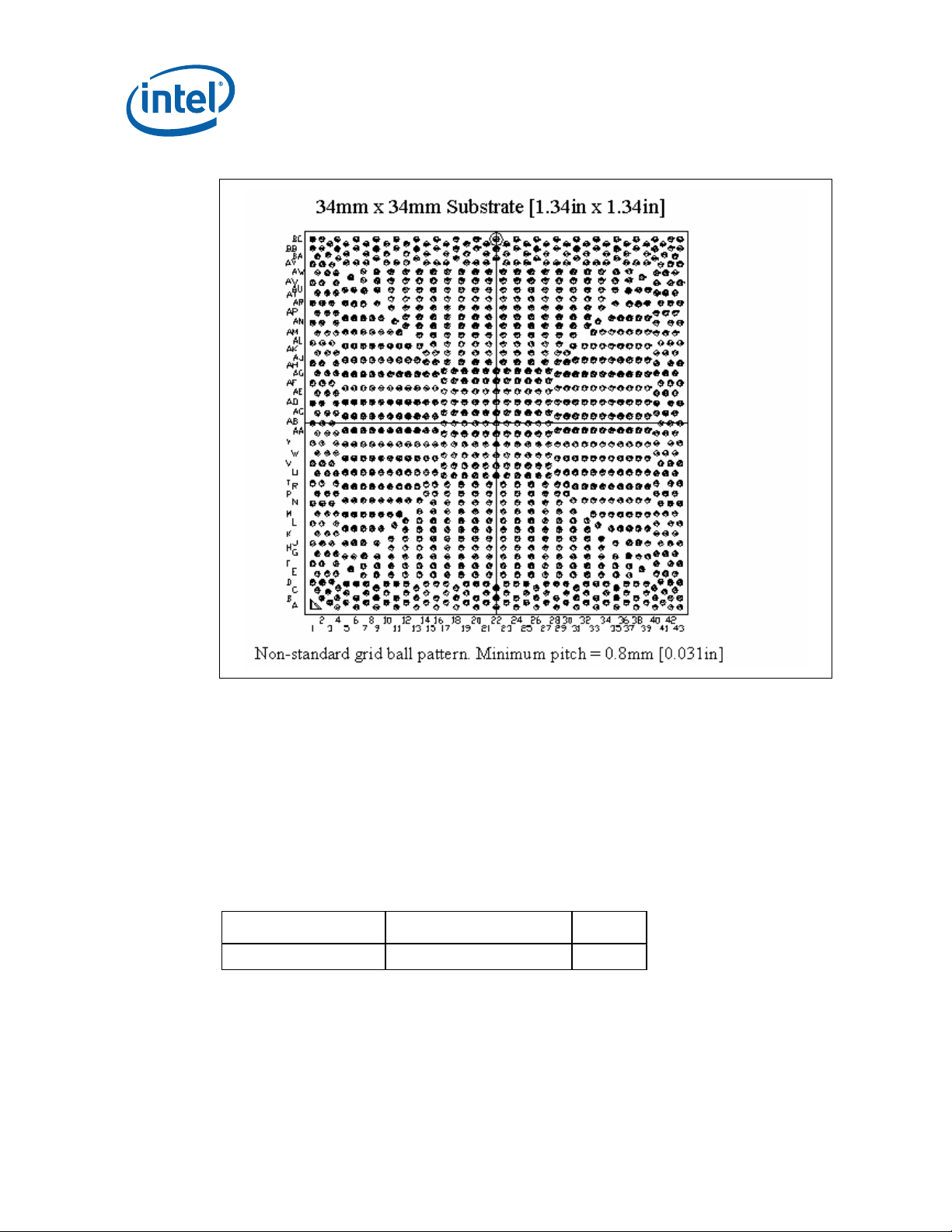
Figure 1. (G)MCH Non-Grid Array
Product Specifications
2.2 Package Loading Specifications
Table 1 provides static load specifications for the chipset package. This mechanical
maximum load limit should not be exceeded during heatsink assembly, shipping
conditions, or standard use conditions. Also, any mechanical system or component
testing should not exceed the maximum limit. The chipset package substrate should
not be used as a mechanical reference or load-bearing surface for the thermal and
mechanical solution.
Table 1. (G)MCH Loading Specifications
Parameter Maximum Notes
Static 15 lbf 1,2,3
NOTES:
1. These specifications apply to uniform compressive loading in a direction normal to the
(G)MCH package.
2. This is the maximum force that can be applied by a heatsink retention clip. The clip must
also provide the minimum specified load on the (G)MCH package.
3. These specif ications are based on limited testing for design characterization. Loading limits
are for the package only.
12 Thermal and Mechanical Design Guidelines
Page 13

Product Specifications
2.3 Thermal Specifications
To ensure proper operation and reliability of the (G)MCH, the temperature must be at
or below the maximum value specified in
thermal enhancements are required to dissipate the heat generated and maintain the
(G)MCH within specifications. Chapter
case temperature measurements.
The (G)MCH must also operate above the minimum case temperature specification
listed in Table 2.
Table 2. (G)MCH Case Temperature Specifications
Parameter Value
3 provides the thermal metrology guidelines for
Table 2. System and component level
T
C-MAX
T
0 °C
C-MIN
NOTE: Thermal specifications assume an attached heatsink is present.
82945G/82945GZ/82945GC GMCH: 99 °C
82945P/82945PL MCH : 103°C
2.4 Thermal Design Power (TDP)
Thermal design power (TDP) is the estimated power dissipation of the (G)MCH based
on normal operating conditions including V
case power intensive applications. This value is based on expected worst-case data
traffic patterns and usage of the (G)MCH and does not represent a specific software
application. TDP attempts to account for expected increases in power due to variation
in (G)MCH current consumption due to silicon process variation, processor speed,
DRAM capacitive bus loading and temperature. However, since these variations are
subject to change, the TDP cannot ensure that all applications will not exceed the TDP
value.
The system designer must design a thermal solution for the (G)MCH such that it
maintains T
specification is a requirement for a sustained power level equal to TDP, and that
MAX
below T
C
for a sustained power level equal to TDP. Note that the T
C-MAX
the case temperature must be maintained at temperatures less than T
operating at power levels less than TDP. This temperature compliance is to ensure
(G)MCH reliability over its useful life. The TDP value can be used for thermal design if
the (G)MCH thermal protection mechanisms are enabled. Intel chipsets incorporate a
hardware-based fail-safe mechanism to help keep the product temperature within
specifications in the event of unusually strenuous usage above the TDP power limit.
and T
CC
while executing real worst-
C-MAX
C-MAX
C-
when
Thermal and Mechanical Design Guidelines 13
Page 14

2.4.1 Methodology
2.4.1.1 Pre-Silicon
To determine TDP for pre-silicon products in development, it is necessary to make
estimates based on analytical models. These models rely on extensive knowledge of
the past chipset power dissipation behavior along with knowledge of planned
architectural and process changes that may affect TDP. Knowledge of applications
available today and their ability to stress various components of the chipset is also
included in the model. Since the number of applications available today is beyond
what Intel can test, only real world high-power applications are tested to predict TDP.
The values determined are used to set specific data transfer rates. The projection for
TDP assumes (G)MCH operation at T
account for process variation.
2.4.1.2 Post-Silicon
Once the product silicon is available, post-silicon validation is performed to assess the
validity of pre-silicon projections. Testing is performed on both commercially available
and synthetic high power applications and power data is compared to pre-silicon
estimates. Post-silicon validation may result in a small adjustment to pre-silicon TDP
estimates.
Product Specifications
. The TDP estimate also includes a margin to
C-MAX
2.4.2 Application Power
Designing to the TDP can ensure that a particular thermal solution meets the cooling
needs of future applications. Testing with currently available commercial applications
has shown that the components may dissipate power levels below the published TDP
specification in Section
2.4.3. Intel strongly recommends that thermal engineers
design to the published TDP specification to develop a robust thermal solution that will
meet the needs of current and future applications.
2.4.3 Specifications
The (G)MCH is estimated to dissipate the Thermal Design Power values provided in
Table 3 when using two DIMMs of 667 MHz (553 MHz for the 82945PL/82945GZ) dual
channel DDR2 with a 1066 MHz (800 MHz for the 82945PL/82945GZ/82945GC)
processor system bus speed. For the 82945G/82945GZ/82945GC GMCH, the graphics
core is assumed to run at 400 MHz. FC-BGA packages have limited heat transfer
capability into the board and have minimal thermal capability without thermal
solutions. Intel requires that system designers plan for an attached heatsink when
using the (G)MCH.
Table 3. (G)MCH Thermal Design Power Specifications
Component System Bus Speed Memory Frequency TDP Value
82945G GMCH
82945GZ GMCH
82945GC GMCH
82945P MCH
82945PL MCH
1066 MHz 667 MHz
800 MHz 533 MHz
800 MHz 667 MHz
1066 MHz 667 MHz
800 MHz 533 MHz
§
22.2 W
22.2 W
22.2 W
15.2 W
15.2 W
14 Thermal and Mechanical Design Guidelines
Page 15

Thermal Metrology
3 Thermal Metrology
The system designer must measure temperatures to accurately determine the thermal
performance of the system. Intel has established guidelines for proper techniques of
measuring (G)MCH component case temperatures.
3.1 Case Temperature Measurements
To ensure functionality and reliability, the (G)MCH is specified for proper operation
when T
surface temperature at the geometric center of the die corresponds to T
T
C
Temperature differences between the temperature of a surface and the surrounding
local ambient air can introduce error in the measurements. The measurement errors
could be due to a poor thermal contact between the thermocouple junction and the
surface of the package, heat loss by radiation and/or convection, conduction through
thermocouple leads, or contact between the thermocouple cement and the heatsink
base (if a heatsink is used). To minimize these measurement errors a thermocouple
attach with a zero-degree methodology is recommended.
is maintained at or below the maximum temperature listed in Table 2. The
C
requires special care to ensure an accurate temperature reading.
. Measuring
C
3.1.1 Thermocouple Attach Methodology
1. Mill a 3.3 mm [0.13 in] diameter hole centered on bottom of the heatsink base.
The milled hole should be approximately 1.5 mm [0.06 in] deep.
2. Mill a 1.3 mm [0.05 in] wide slot, 0.5 mm [0.02 in] deep, from the centered hole
to one edge of the heatsink. The slot should be in the direction parallel to the
heatsink fins (see
3. Attach thermal interface material (TIM) to the bottom of the heatsink base.
4. Cut out portions of the TIM to make room for the thermocouple wire and bead.
The cutouts should match the slot and hole milled into the heatsink base.
5. Attach a 36 gauge or smaller calibrated K-type thermocouple bead or junction to
the center of the top surface of the die using a high thermal conductivity cement.
During this step, make sure no contact is present between the thermocouple
cement and the heatsink base because any contact will affect the thermocouple
reading. It is critical that the thermocouple bead makes contact with the
die (see
6. Attach heatsink assembly to the (G)MCH and route thermocouple wires out
through the milled slot.
Figure 2).
Figure 3).
Thermal and Mechanical Design Guidelines 15
Page 16

Thermal Metrology
Figure 2. 0° Angle Attach Methodology (top view, not to scale)
Figure 3. 0° Angle Attach Heatsink Modifications (generic heatsink side and bottom
view shown, not to scale)
3.2 Airflow Characterization
Figure 4 describes the recommended location for air temperature measurements
measured relative to the component. For a more accurate measurement of the
average approach air temperature, Intel recommends averaging temperatures
recorded from two thermocouples spaced about 25 mm [1.0 in] apart. Locations for
both a single thermocouple and a pair of thermocouples are presented.
16 Thermal and Mechanical Design Guidelines
Page 17

Thermal Metrology
Figure 4. Airflow Temperature Measurement Locations
Airflow velocity should be measured using industry standard air velocity sensors.
Typical airflow sensor technology may include hot wire anemometers.
Figure 4
provides guidance for airflow velocity measurement locations. These locations are for
a typical JEDEC test setup and may not be compatible with chassis layouts due to the
proximity of the processor to the (G)MCH. The user may have to adjust the locations
for a specific chassis. Be aware that sensors may need to be aligned perpendicular to
the airflow velocity vector or an inaccurate measurement may result. Measurements
should be taken with the chassis fully sealed in its operational configuration to achieve
a representative airflow profile within the chassis.
§
Thermal and Mechanical Design Guidelines 17
Page 18

Thermal Metrology
18 Thermal and Mechanical Design Guidelines
Page 19

Reference Thermal Solution
4 Reference Thermal Solution
The reference component thermal solution for the (G)MCH for ATX platforms uses two
ramp retainers, a wire preload clip, and four custom MB anchors. The Intel Balanced
Technology Extended (BTX) reference design uses a Z-clip attach for the (G)MCH
heatsink. This chapter provides detailed information on operating environment
assumptions, heatsink manufacturing, and mechanical reliability requirements for the
(G)MCH.
4.1 Operating Environment
The operating environment of the (G)MCH will differ depending on system
configuration and motherboard layout. This section defines operating environment
boundary conditions that are typical for ATX and BTX form factors. The system
designer should perform analysis on the platform operating environment to assess any
impact to thermal solution selection.
4.1.1 ATX Form Factor Operating Environment
In ATX platforms, an airflow speed of 0.76 m/s [150 lfm] is assumed to be present
25 mm [1 in] in front of the heatsink air inlet side of the attached reference thermal
solution. The system integrator should note that board layout may be such that there
will not be 25mm [1in] between the processor heatsink and the (G)MCH. The potential
for increased airflow speeds may be realized by ensuring that airflow from the
processor heatsink fan exhausts in the direction of the (G)MCH heatsink. This can be
achieved by using a heatsink providing omni directional airflow, such as a radial fin or
“X” pattern heatsink. Such heatsinks can deliver airflow to both the (G)MCH and other
areas like the voltage regulator, as shown in
placement should ensure that the (G)MCH heatsink is within the air exhaust area of
the processor heatsink.
Note that heatsink orientation alone does not ensure that 0.76 m/s [150 lfm]
airflow speed will be achieved. The system integrator should use analytical or
experimental means to determine whether a system design provides adequate airflow
speed for a particular (G)MCH heatsink.
The local ambient air temperature, T
assumed to be 47 °C. The thermal designer must carefully select the location to
measure airflow to get a representative sampling. These environmental assumptions
are based on a 35 °C system external temperature measured at sea level.
, at the (G)MCH heatsink in an ATX platform is
A
Figure 5. In addition, the (G)MCH board
Thermal and Mechanical Design Guidelines 19
Page 20

Reference Thermal Solution
Figure 5. Processor Heatsink Orientation to Provide Airflow to (G)MCH Heatsink on an
ATX Platform
Airflow Direction
Airflow Direction
Airflow Direction
Airflow Directio n
Airflow Direction
Airflow Directio n
(G)MCH Heatsink
Airflow Direction
Airflow Direction
TOP VIEW
Omi Direc t ional Flow
Processor Heatsink
(Fan Not Shown)
Proc_HS_Orient_ATX
Other methods exist for providing airflow to the (G)MCH heatsink, including the use of
system fans and/or ducting, or the use of an attached fan (active heatsink).
4.1.2 Balanced Technology Extended (BTX) Form Factor Operating Environment
The operating environment for the (G)MCH in typical BTX systems has not been
profiled. This section provides operating environment conditions based on what has
been exhibited on the Intel micro-BTX reference design. On a BTX platform, the
(G)MCH obtains in-line airflow directly from the processor thermal module. Since the
processor thermal module provides lower inlet temperature airflow to the processor,
reduced inlet ambient temperatures are also often seen at the (G)MCH as compared to
ATX. An example of how airflow is delivered to the (G)MCH on a BTX platform is
shown in
Figure 6.
The local ambient air temperature, TA, at the (G)MCH heatsink in the Intel micro-BTX
reference design is predicted to be ~45 °C. The thermal designer must carefully select
the location to measure airflow to get a representative sampling. These environmental
assumptions are based on a 35 °C system external temperature measured at sea
level.
Note: The local ambient air temperature is a projection based on anticipated power
increases on a 2005 platform and may be subject to change in future revisions of this
document.
20 Thermal and Mechanical Design Guidelines
Page 21

Reference Thermal Solution
Figure 6. Processor Heatsink Orientation to Provide Airflow to (G)MCH Heatsink on a
Balanced Technology Extended (BTX) Platform
Balanced Technology
Airflow Direction
(G)MCH
Extended (BTX) Thermal
Module Assembly Over
Processor
Top View
Proc_HS_Orient
4.2 Mechanical Design Envelope
The motherboard component keep-out restrictions for the (G)MCH on an ATX platform
are included in
restrictions for the (G)MCH on a BTX platform are included in
System integrators should ensure no board or chassis components would intrude into
the volume occupied by the (G)MCH thermal solution.
Appendix B, Figure 10. The motherboard component keep-out
4.3 Thermal Solution Assembly
The reference thermal solution for the (G)MCH for an ATX platform is shown in
Figure 7 and Appendix B and is an aluminum extruded heatsink that uses two ramp
retainers, a wire preload clip, and four custom motherboard anchors. The heatsink is
attached to the motherboard by assembling the anchors into the board, placing the
heatsink over the (G)MCH and anchors at each of the corners, and securing the plastic
ramp retainers through the anchor loops before snapping each retainer into the fin
gap. The assembly is then sent through the wave process. Post wave, the wire preload
clip is assembled using the hooks on each of the ramp retainers. The clip provides the
mechanical preload to the package. A thermal interface material (Chomerics* T710) is
pre-applied to the heatsink bottom over an area that contacts the package die.
The reference thermal solution for the (G)MCH for a BTX platform is shown in
Figure 8. The heatsink is aluminum extruded and uses a Z-clip for attach. The clip is
secured to the system motherboard via two solder-down anchors around the (G)MCH.
The clip helps to provide a mechanical preload to the package via the heatsink. A
thermal interface material (Chomerics* T710) is pre-applied to the heatsink bottom
over an area in contact with the package die.
Figure 11.
The ATX reference thermal solution differs from the BTX reference solution because a
BTX platform requires a Support and Retention Mechanism (SRM) that helps to meet
the mechanical requirements listed in
Thermal and Mechanical Design Guidelines 21
Table 4.
Page 22

Figure 7. ATX GMCH Heatsink Installed on Board
Reference Thermal Solution
22 Thermal and Mechanical Design Guidelines
Page 23

Reference Thermal Solution
Figure 8. Balanced Technology Extended (BTX) GMCH Heatsink Installed on Board
Thermal and Mechanical Design Guidelines 23
Page 24

Reference Thermal Solution
4.4 Environmental Reliability Requirements
The environmental reliability requirements for the reference thermal solution are
shown in
plans should be defined by the user based on anticipated use conditions and resulting
reliability requirements.
Table 4. Reference Thermal Solution Environmental Reliability Requirements
Table 4. These should be considered as general guidelines. Validation test
Test1 Requirement Pass/Fail
Mechanical
Shock
Random
Vibration
Thermal
Cycling
Unbiased
Humidity
NOTES:
1. The above tests should be performed on a sample size of at least 12 assemblies from 3
different lots of material.
2. Additional Pass/Fail Criteria may be added at the discretion of the user.
• 3 drops for + and - directions in each of 3
perpendicular axes (i.e., total 18 drops).
• Profile: 50 G trapezoidal waveform, 11 ms duration,
4.3 m/s [170 in/s] minimum velocity change.
• Setup: Mount sample board on test fixture. Include
550 g processor heatsink.
• Duration: 10 min/axis, 3 axes
• Frequency Range: 5 Hz to 500 Hz
• Power Spectral Density (PSD) Profile: 3.13 g RMS
• -40 °C to +85 °C, 900 cycles Thermal
• 85 % relative humidity / 55 °C, 500 hours Visual Check
Criteria2
Visual\Electrical
Check
Visual/Electrical
Check
Performance
§
24 Thermal and Mechanical Design Guidelines
Page 25

Enabled Suppliers
Appendix A Enabled Suppliers
Current suppliers for the Intel® 945G/945GZ/945GC/945P/945PL Express chipset
(G)MCH reference thermal solution are listed in
Table 5. (G)MCH ATX Intel Reference Heatsink Enabled Suppliers
Table 5 and Table 6.
Supplier Intel Part
CCI (Chaun Choung
Technology Corp)
WiesonElectronic Co.
Foxconn/HonHai
Precision
Foxconn/HonHai
Precision
Number
C85366-001
(heatsink)
C85370-001
(ramp
retainer)
C85373-001
(wire clip)
C85376-001
(anchor)
C85366-001
(heatsink)
C85370-001
(ramp
retainer)
C85373-001
(wire clip)
C85376-001
(anchor)
Vendor Part
Number
00C863501A
334C863501A
334C863502A
G2100C888-143 Rick Lin - +886 (-2) -
2Z802-016
3EE77-002
3KS02-066
2Z802-015 Jack Chen – (714) 626-1233
Contact Information
Monica Chih - +886 (-2) 29952666
monica_chih@ccic.com.tw
Harry Lin - (714) 739-5797
hlinack@aol.com
26471896 ext.6342
rick@wieson.com.tw
Jack Chen – (714) 626-1233
Jack.chen@foxconn.com
Jack.chen@foxconn.com
Note: These vendors and devices are listed by Intel as a convenience to Intel's general
customer base, but Intel does not make any representations or warranties whatsoever
regarding quality, availability, reliability, functionality, or compatibility of these
devices. This list and/or these devices may be subject to change without notice.
Thermal and Mechanical Design Guidelines 25
Page 26

Enabled Suppliers
Table 6. (G)MCH Balanced Technology Extended (BTX) Intel Reference Heatsink
Enabled Suppliers
Supplier Intel Part
CCI (Chaun
Choung
Technology
Corp.)
AVC (Asia Vital
Components)
Foxconn/HonHai
Precision
Number
C57359-001 00C863401A Monica Chih - +886 (-2) -
C57359-001 S909700001 David Chao - +886 (-2) -2299-
C57359-001 2Z802-010 Jack Chen – (714) 626-1233
Vendor Part
Number
§
Contact Information
29952666
monica_chih@ccic.com.tw
Harry Lin - (714) 739-5797
hlinack@aol.com
6930 x619
david_chao@avc.com.tw
Jack.chen@foxconn.com
26 Thermal and Mechanical Design Guidelines
Page 27

Mechanical Drawings
Appendix B Mechanical Drawings
The following table lists the mechanical drawings available in this document.
Drawing Name Page
(G)MCH Package Drawing 28
(G)MCH Component Keep-Out Restrictions for ATX Platforms 29
(G)MCH Component Keep-Out Restrictions for Balanced Technology Extended
(BTX) Platforms
(G)MCH Reference Heatsink for ATX Platforms – Sheet 1 31
(G)MCH Reference Heatsink for ATX Platforms – Sheet 2 32
(G)MCH Reference Heatsink for ATX Platforms – Anchor 33
(G)MCH Reference Heatsink for ATX Platforms – Ramp Retainer Sheet 1 34
(G)MCH Reference Heatsink for ATX Platforms – Ramp Retainer Sheet 2 35
(G)MCH Reference Heatsink for ATX Platforms – Wire Preload Clip 36
. (G)MCH Reference Heatsink for Balanced Technology Extended (BTX)
Platforms
(G)MCH Reference Heatsink for Balanced Technology Extended (BTX)
Platforms – Clip
(G)MCH Reference Heatsink for Balanced Technology Extended (BTX)
Platforms – Heatsink Assembly
Number
30
37
38
39
NOTE: Unless otherwise specified, all figures in this appendix are dimensioned in millimeters.
Dimensions shown in brackets are in inches.
Thermal and Mechanical Design Guidelines 27
Page 28

Mechanical Drawingss
Figure 9. (G)MCH Package Drawing
28 Thermal and Mechanical Design Guidelines
Page 29

.345[]
4X 8.76
NO COMPONENTS THIS AREA
.345[]
4X 8.76
DETA IL A
SCALE 8
0.97 .038[]
8X 1.42[.056] TRACE KEEPOUT
8X PLATED THRU HOLE
.200[]
4X 5.08
.072[]
4X 1.84
EAST
2.9134[]
DETAIL A
74
2.398[]
60.92
1 HOLE PLACEMENT FABRICAT ION
NOTES:
TOLERANCE PER INTEL 454979, CLASS 1,2,3
2. HEATSINK COMPONENT HEIGHT NOT TO EXCEED
38.1MM ABOVE MOTHERBOARD SURFA CE.
MAX 25 [1.000]
COMPONENT HEIGHT
MAX 1.27 [.050]
COMPONENT HEIGHT
COMPONENT CENTER
(NON-MCH COMP ONENT S)
.1575[]
4
135
1.85[]
47
Thermal and Mechanical Design Guidelines 29
2.386[]
1.055[]
1.890[]
60.6
26.79
48
NORTH
1.803[]
45.79
2.638[]
67
3.189[]
81
Mechanical Drawings
Figure 10. (G)MCH Component Keep-Out Restrictions for ATX Platforms
Page 30

Mechanical Drawingss
.073[]
4X 1.85
.165[]
4X 4.19
8X 1. 42[. 0 56] TRA CE KEE POUT
8X P L AT ED THRU HO L E0.97 .038[]
N O C O MPON EN T S T H IS AR EA
.345[]
4X 8.76
.200[]
4X 5.08
D ETAIL A
D E TAIL A
SCALE 8
.083[]
4X 2.1
COM PONENT CENTER
MAX 1 .7 8 [.07 0 ] C O MPON EN T H EIG H T
.100[]
.225[]
2X 2.54
2X 5.72
.130[]
2X 3.3
1 . H O L E PLAC EMENT FABR IC AT IO N
NOTES:
.090[]
DETAIL B
2X 2.29
TOLE RANCE PER INTEL 454 979, CLASS 1,2, 3
2. HEATS INK COM PONENT HEIGHT NO T TO EX CEED
26.9 M M A BOVE MOT HERB O ARD SURFACE .
SCALE 5
MAX 1 .2 7[.0 5 0 ] C O MPON EN T H EIGH T
B
1.900[]
48.26
2. 2 00[]
55.8 8
2.44 0[]
61.98
Figure 11. (G)MCH Component Keep-Out Restrictions for Balanced Technology Extended (BTX) Platforms
DETAIL B
SCALE 4
1.83 0[]
46.4 8
30 Thermal and Mechanical Design Guidelines
Page 31

NOT E S: 1. THIS DRAW I NG TO B E USE D IN CO NJUNCT IO N W IT H SUP PLIED 3D
5 MA RK P ART W IT H INT EL P/N A ND REV ISIO N APP RO X
DATA BAS E F ILE. ALL DIME NSIO NS AND T O LERANCES O N TH IS
DRAWING TA KE PRECEDENCE OVER SUPPLIED FILE AND ARE
APPLICABLE AT PART FREE, UNCONSTRAINED STATE UNLESS
INDICAT ED O T HE RW ISE .
2. TO LERANCE S O N D IME NSIO NE D AND UNDIM E NSIO NE D
FEATURES UNLESS OTHERWISE SPECIFIED:
DIME NSIO NS ARE I N MILLIM ET ERS .
TOLERANCES:
6 CRITICA L TO F UNCTIO N DIME NSIO N
LINE AR 0.25
ANG ULAR 1
3. M AT E RI AL: 6063-T 5 A LUM IN UM
4. FINISH: NO NE
WHERE SHOW N PER INTEL MARKING STANDARD 164997
7. EDG ES SHO W N AS SHARP R 0.1 MAX.
8. TO O LING REQ UIRED T O M AKE T HIS PA RT S HALL BE T HE
PROPERTY O F INTEL, AND SHALL BE PERMANENTLY MARKED
WIT H INTEL'S NAME AND APPROPRIATE PART NUMBER.
9. ALL SECO NDARY UNIT DIM ENSIO NS ARE FO R RE F ERENCE O NLY.
10. ALL DIMENSIONS SHOWN SHALL BE MEASURED FOR FAI
11. REMO VE ALL BURRS O R SHARP EDGES ARO UND PERIMETER
OF P ART. SHARPNESS OF EDGE S SUBJECT TO HANDLING ARE
REQ UIRED T O M EET UL1439 TEST.
.005[]
.148
TYP 63.7 5 0.15
1.398[]
TYP 35.5
FULL RO UND
2.307[]
1.850[]
47
2X 58.6
SEE DETAIL B
SEE DETAIL B
1.201[]
30.5
SPACING
14X E Q UA L
.157[]
4
659.28
.005[]
2X
0.15
2.334
.005[]
.047
16X 1.2 0.15
SEE DE TA IL A
SEE DE TA IL A
.005[]
1.890
2X 648 0.15
.005[]
.106
8X 2. 7 0. 15
1.417[]
36
SPA CING
7X E Q U A L
3.150[]
2X 80
Mechanical Drawings
Figure 12. (G)MCH Reference Heatsink for ATX Platforms – Sheet 1
Thermal and Mechanical Design Guidelines 31
Page 32

Mechanical Drawingss
.02 4[]
2X 60.6
TYP 135
.020[]
R0. 5
66.72 0.15
.005[]
.265
NO B URR ALL ARO UND
61.5 0.15
.039[]
TYP R 1
.003[]
.108
.1575[]
TYP 62.75 0.1
TYP 4
DETA IL B
SCALE 5
TYP DETAIL A
SCALE 5
TYP.
.005[]
.059
Figure 13. (G)MCH Reference Heatsink for ATX Platforms – Sheet 2
.630[]
16
0.1 [.003]
2X 15
2.5984[]
66
.591[]
1.004[]
25.5
CH OM ER ICS:
69-12-22350-T 710
4X 45 X 1 [.039]
BOTT OM VIEW
5
32 Thermal and Mechanical Design Guidelines
Page 33

2X CHAMF ER ALL ARO UND
CONTACT TO INSULATOR INTERFACE
AT SUPPLIERS OPTIO N
+.000
-.002
0
-0.07
.025
0.64
[]
.003[]
.030
2X 60.77 0.1
.005[]
.300
7.62 0.15
NOT ES: 1. THIS DRAW ING T O BE USED IN CO NJUNCTIO N W IT H SUPP LIED 3D
DATA BASE FILE. ALL DIMENSIO NS A ND TO LERANCES O N THIS
DRAWING T AKE PRECEDENCE OVER SUPPLIED F ILE AND ARE
APPLICABLE AT PART FREE, UNCONSTRAINED STATE UNLESS
INDICATED O T HERW ISE .
2. TOLERA NCES O N DIME NSIO NED AND UNDIMENS IO NED
FEA TURES UNLESS O THE RW ISE SP ECIF IED:
DIMENSIONS ARE IN MILLIMET ERS.
FO R FE AT URE SIZ ES < 10MM: LINEAR .07
45 X 0.2 M IN
2X 45 2
.005[]
.098
2.5 0.15
2X 3.94 0.15
FO R FE AT URE SIZ ES > 10MM: LINEAR .08
ANG LES: 0.5
3. M AT E RIA LS:
.005[]
.155
.001[]
.020
2X 0.5 0.0 5
6 CRITICAL TO F UNCTIO N DIM ENSIO N
INSULATO R: PO LYCARBO NAT E T HERM O PLAST IC, UL 94V -0, BLACK (739)
(REF. G E LEXAN 3412R-739)
CONTACT: BRASS O R EQUIVALENT UPON INT EL APPRO VAL
CON TA CT F INIS H: .000050u" M IN. NICK EL UNDER P LAT ING ;
SO LDE R T A ILS , 0.000100" M IN T IN O NLY SO LD ER (LE AD F RE E).
5. MARK W IT H INTE L P/N AND REVISIO N PE R INTEL MA RKING
STANDARD 164997; PER SEC 3.8 (POLYETHYLENE BAG)
7. ALL DIMENS IONS SHO W N SHALL BE M EASURE D FO R FA I
8. NO T E RE M O VE D
9. DEG AT E: F LUSH T O 0.35 BELO W S T RUCTUR AL TH ICKNE SS
(GAT E W ELL OR G A TE RECESS A CCEPT ABLE)
10. F LAS H: 0. 15 MA X .
11. SIN K: 0.25 M AX .
12. EJECTOR MARKS: FLUSH TO -0.25
13. PARTING LINE MISM AT CH NOT TO E XCEED 0.25.
14. EJECTIO N PIN BO SSE S, G AT ING , AND TO O LING INSERT S REQ UIRE
INTEL'S APPRO VAL PRIO R T O TO O L CONS TRUCT IO N.
ALL EJECTION PIN BOSSES AND GATE FEATURES SHOWN
ARE F O R REF E RENCE O NLY.
15. EDGES SHOW N AS SHARP R 0.1 M AX.
16. TOO LING REQ UIRED TO M AKE THIS P ART S HALL BE THE
PROPERTY OF INTEL, AND SHALL BE PERMANENTLY MARKED
WITH INTEL'S NAME AND APPROPRIATE PART NUMBER.
17. ALL S ECO NDARY UNIT DIM ENSIO NS A RE F OR RE FERE NCE O NLY.
.004[]
.399
2X 10.13 0.12
+.000
-.002
0
-0.07
.025
0.64
[]
65.08 0.12
.004[]
.200
.030[]
.157[]
2X 4
Mechanical Drawings
Figure 14. (G)MCH Reference Heatsink for ATX Platforms – Anchor
2X 0.75
65.21 0.12
.004[]
.205
.004[]
.308
4X 67.83 0.12
Thermal and Mechanical Design Guidelines 33
Page 34

Mechanical Drawingss
5 MARK PART W ITH INTEL P/N, REVISION, CAVITY NUMBER
NOTES: 1. THIS DRA W ING T O B E USE D IN CO NJUNCT IO N W IT H S UPPLIED 3D
DATABASE FILE. ALL DIM ENSIONS AND T OLERANCES O N THIS
670.49
DRAWING TAKE PRECEDENCE OVER SUPPLIED FILE AND ARE
APPLICABLE AT PART FREE, UNCO NSTRAINED STATE UNLESS
INDICAT E D O T HERW ISE.
2. TO LERANCES O N DIM ENSIO NE D AND UNDIME NSIO NED
FEATURES UNLESS OT HERWISE SPECIFIED:
DIME NSIO NS ARE IN MILLIM ET ERS.
FO R FEATURE SIZES < 10MM : LINEAR .07
2.775[]
661.51
2.422[]
FO R FEATURE SIZES BETWEEN 10 AND 25 M M: LINEAR .08
FO R FEATURE SIZES BETWEEN 25 AND 50 M M: LINEAR .10
FO R FEATURE SIZES > 50MM : LINEAR .18
ANG LES: 0.5
3. MAT ERIA L:
A) TYPE: ENVIRONMENTALLY CO MPLIANT THERMOPLASTIC O R
EQ UIV ALENT UPO N IN TE L APP RO VAL (REF . G E LEX AN 500ECR-739)
B) CRITICAL MECHANICAL MATERIAL PROPERTIES
FO R EQUIVALENT M ATERIAL SELECTION:
TE NSILE YIELD ST RENG T H (AST M D638) > 57 MPa
TENSILE ELO NGATION AT BREAK (ASTM D638) >= 46%
F LEX URA L M O D ULUS (AS T M D638) 3116 M Pa 10%
SO F T ENING T EM P (VICAT , RAT E B ): 154 C
C) CO LOR: APPROXIMATING BLACK, (REF GE 739)
6 CRIT ICAL TO F UNCT IO N DIM ENS IO N
D) REG RIND: 25% PE RMIS SIB LE.
E) VO L UM E - 1. 73e+ 03 C UB IC -M M (RE F )
W E IG HT - 2.16 G RAM S (REF )
AND DATE CO DE APPROX W HERE SHOWN PER INTEL M ARKING
ST A NDA RD 164997
7. ALL DIMENSIO NS SHOWN SHALL BE M EASURED F OR FAI
8. NOT E REM O VED
9. DEGA TE: FLUSH T O 0.35 BELOW ST RUCT URAL THICKNES S
(G AT E W E LL OR G A TE RECE SS A CCEP TA BLE)
10. F LAS H: 0. 15 MA X .
11. SIN K: 0. 25 MA X.
12. EJECTOR MARKS: FLUSH TO -0.25
13. PARTING LINE MISM A TCH NO T TO E XCEE D 0.25.
14. EJECTION PIN BOSSES, GATING, AND TOO LING INSERTS REQUIRE
INTEL'S APPROVAL PRIO R TO T OO L CONSTRUCT ION.
ALL EJECTION PIN BOSSES AND GATE FEATURES SHOWN
ARE FO R REFERENCE ONLY.
15. EDGES SHOW N AS SHARP R 0.1 MAX.
16. TO OLING REQUIRED TO M AKE THIS PART SHALL BE THE
PROPERTY OF INTEL, AND SHALL BE PERMANENTLY M ARKED
W ITH INTEL'S NAME AND APPROPRIATE PART NUMBER.
17. ALL S ECO NDARY UNIT DIM ENSIO NS A RE F O R REF ERENCE O NLY.
Figure 15. (G)MCH Reference Heatsink for ATX Platforms – Ramp Retainer Sheet 1
5
62 0.05
SEE DETAIL C
SEE DETAIL C
1.100[]
.118[]
3
2X 27.95
1.225[]
2X 31.1
.001[]
.079
SEE DETAIL ASEE DETAIL A
34 Thermal and Mechanical Design Guidelines
Page 35

.157[]
4
65.56
.219[]
DET AIL C
SCALE 10
.114[]
2X 62.9
.252[]
6.4
.227[]
2X 65.76
SECT IO N B-B
.047[]
1.19
60.5
61.75
.020[]
.069[]
63.15
.108[]
.124[]
2.75
B
64. 7 5
.187[]
.205[]
5.2
2X DET AIL A
SCALE 20
.258[]
6.55
.118[]
3
B
Mechanical Drawings
Figure 16. (G)MCH Reference Heatsink for ATX Platforms – Ramp Retainer Sheet 2
Thermal and Mechanical Design Guidelines 35
Page 36

Mechanical Drawingss
A2
.019[]
0.5
1. 8 3 5
46.6
A
FA R SIDE
A2
TYP R1.8
A3
FAR SI DE
A3
NOTES: 1. THIS DRAWING T O BE USED IN CORRELATION WITH SUPPLIED 3D
DATA BAS E F ILE. ALL DIMENS IO NS AND T O LERA NCES O N T HIS
DRAWING T AKE PRECEDENCE O VER SUPPLIED FILE AND ARE
APPLICABLE AT PART FREE, UNCO NSTRAINED ST ATE UNLESS
.071[]
INDICAT ED O THE RW ISE .
2. TO LERANCE S O N DIM ENSIO NE D AND UNDIM ENSIO NE D
FEATURES UNLESS OTHERWISE SPECIFIED:
DIME NSIO NS ARE IN M ILLIME TE RS.
TO LERA NCES : LINEAR 0.25
ANGLES: 1
3. M A T E RI AL:
A) TYPE: ASTM A228 MUSIC WIRE 1.8 0.1M M 4
4 CRIT ICAL TO F UNCT ION DIME NSIO N
PLATING : ELECTRO-LESS NICKEL OR EQUIVALENT UPON
INTEL APPROVAL.
B) CRITICAL M ECHANI CAL MAT E RIAL PRO PE RTIE S
FOR EQUIVALENT MATERIAL SELECTIO N:
TENS ILE YIELD ST RENG T H (AST M D638) > 965 MPa
FLE X URA L M O D ULUS (A S T M D638) 210 G P a 10%
5. MARK W IT H INT EL P/N AND REV ISIO N P ER INT EL M ARK ING
STANDARD 164997; PER SEC 3.8 (POLYETHYLENE BAG)
6. REM O VE ALL SHARP EDGES AND BURRS.
7. ALL DIMENSIO NS SHO W N SHA LL BE M EAS URED FO R F AI
8. ALL SECO NDARY UNIT DIM ENSIO NS ARE F O R REF ERE NCE O NLY.
A
SECTION A-A
.104[]
2.65
A
A1
.019[]
2.431
61.74 0. 5
1.459[]
37.06
.019[]
.760
19.3 0.5
Figure 17. (G)MCH Reference Heatsink for ATX Platforms – Wire Preload Clip
.019[]
1.075
27.3 0.5
A
2X 90
A2 A3
427. 7
1.090[]
36 Thermal and Mechanical Design Guidelines
Page 37

N OT ES:
.953[]
3 . CRITICAL TO FUNCTION DIMENSIONS
1. PROCUREMENT SPECIFICATION A02160 SHALL APPLY
2. REMOVE ALL BURRS AND SHARP EDGES
.009[]
.118
3 0.25
.591[]
()15
24.2
3
.007[]
.118
3 0.2
R0 TO 0.5[.020]
.046[]
C
2.20[]
()55.88
1.30[]
()33
Mechanical Drawings
Figure 18. (G)MCH Reference Heatsink for Balanced Technology Extended (BTX) Platforms
16X 1.17
R0 TO FULL
1.885[]
47.88
15X EQUAL SPACES
B
.08[]
()1.94
FULL R
2X 7.25 0.2
A
.007[]
.285
.046[]
2X 1.17
3
.007[]
.134
3.4 0.2
.748[]
19
.047[]
2X 1.2
0.08 [.003]
0.25 [.009] B C
.748[]
19
Thermal and Mechanical Design Guidelines 37
Page 38

10.0
WITHIN
W IR E TER MIN ATION
.161[]
Mechanical Drawingss
4.1
.990[]
25.14
A
4 CRIT ICAL T O FUNCTION DIMENSIONS
NOTES:
1. REMOVE ALL SHAR P EDGES AND BU RR S
2. MATERIAL: ASTM A228 MUSIC WIRE 1.8 MM STOCK
3. TOTAL WI RE LENGTH = 121. 9 M M
5. PLATING: ELEC TRO-LESS NICKEL
.404[]
()10.27
VIEW A
.150[]
3.8
4
A2
SECTION B-B
SCALE 10:1
FAR SI DE
A1
B2X 90
.071[]
()1.80
27.3
Figure 19. (G)MCH Reference Heatsink for Balanced Technology Extended (BTX) Platforms – Clip
F AR S IDE
F AR SIDE
A2
A3
B
1.075[]
1.390[]
35.3
.039[]
2.465
62.6 1
1.030[]
2X 26.16
DE TA IL C
SCALE 8:1
A
47.36
.071[]
4X R 1 .8
A
A1
.150[]
()3.80
.051[]
1.3
1.865[]
.049[]
.349
8.87 1.25
4
R
A3
SEE DETAIL C
A
TYP
38 Thermal and Mechanical Design Guidelines
Page 39

B
NO TES:
1. THIS DRAWING TO BE USED IN CON JU NCTION WITH SUPPLIED 3D
DATABASE FILE. ALL DIMENS IONS AND TO LERANCES ON THIS
DRAW I NG TAKE PRECEDENCE OVER SUPPLIED FIL E AN D AR E
APPLI CA BL E AT PAR T FREE, UNCO NSTRAINED STATE UNLESS
3
5 .ASSEMBLY TO BE MARKED W ITH IN TEL P/ N APPR OX. WHER E SH OWN.
INDICATED OTHERWISE.
2. FINISH: NONE
3. ALL SECONDARY UNIT DIMENSIONS ARE FOR REFERENCE ONLY. TOLERANCES
SHAL L BE C ALCUL ATED FROM PRIMARY UNI TS TO AVOID TRUN C ATION ERRORS.
4. I TEMS WITHOUT INTEL PAR T NUMBER SH AL L BE MANAGED
AND PR O CURED BY SUPP L I ER
6. ATTACH THER MAL I N TERFACE MATERIAL WHERE SH OWN. R EMO VABLE PROTECTIVE
BARRI ER APPL I ED OVER INTERFACE MATERI AL.
.748[]
2.200[]
()19
()55.88
C
1.299[]
()33
.748[]
()19
0.25 [.009] A B C
1
2
5
Mechanical Drawings
Figure 20. (G)MCH Reference Heatsink for Balanced Technology Extended (BTX) Platforms – Heatsink Assembly
Thermal and Mechanical Design Guidelines 39
 Loading...