

Page 1

8S648-RZ /
8S648-RZ-C
Intel® Pentium® 4 Processor Motherboard
User's Manual
Rev. 1001
12ME-8S648RZ-1001
Copy ri ght
© 2003 GIGABYTE TECHNOLOGY CO., LTD
Copyright by GIGA-BYTE TECHNOLOGY CO., LTD. ("GBT"). No part of this manual may be reproduced or transmitted in any from
without the expressed, written permission of GBT.
Tra demar ks
Third-party brands and names are the property of their respective owners.
Not ice
Please do not remove any labels on motherboard, this may void the warranty of this motherboard.
Due to rapid change in technology, some of the specifications might be out of date before publication of this booklet.
The author assumes no responsibility for any errors or omissions that may appear in this docum ent nor does the author make a
com mitment to update the information contained herein.
Page 2
Mar. 20, 2004
Mother Board
8S648-RZ
Mar. 20 ,2004
Motherboard
8S648-RZ
Page 3

Preparing Your Computer
Computer motherboards and expansion cards contain very delicate Integrated Circuit (IC) chips. To
protect them against damage from static electricity, you should follow some precautions whenever you
work on your computer.
1. Unplug your computer when working on the inside.
2. Use a grounded wrist strap before handling computer components. If you do not have one,
touch both of your hands to a safely grounded object or to a metal object, such as the power
supply case.
3. Hold components by the edges and try not touch the IC chips, leads or connectors, or other
components.
4. Place components on a grounded antistatic pad or on the bag that came with the components
whenever the components are separated from the system.
5. Ensure that the ATX power supply is switched off before you plug in or remove the ATX power
connector on the motherboard.
Installing the motherboard to the chassis
If the motherboard has mounting holes, but they don't line up with the holes on the base and there
are no slots to attach the spacers, do not become alarmed you can still attach the spacers to the
mounting holes. Just cut the bottom portion of the spacers (the spacer may be a little hard to cut off, so
be careful of your hands). In this way you can still attach the motherboard to the base without worrying
about short circuits. Sometimes you may need to use the plastic springs to isolate the screw from the
motherboard PCB surface, because the circuit wire may be near by the hole. Be careful, don't let the
screw contact any printed circuit write or parts on the PCB that are near the fixing hole, otherwise it
may damage the board or cause board malfunctioning.
Page 4

Table of Contents
English
Chapter 1 Introduction................................................................................................5
Chapter 2 BIOS Setup ............................................................................................. 19
Features Summary...........................................................................................................................5
8S648-RZ Series Motherboard Layout.............................................................................................6
Block Diagram .................................................................................................................................. 7
Hardware Installation Process ......................................................................................................... 8
Step 1: Install the Central Processing Unit (CPU)..........................................................................8
Step 1-1: CPU Installation .................................................................................................9
Step 1-2: CPU Cooling Fan Installation ............................................................................ 9
Step 2: Install Memory Modules....................................................................................................10
Step 3: Install AGP Card ............................................................................................................... 11
Step 4: Install I/O Peripherals Cables ........................................................................................... 11
Step 4-1: I/O Back Panel Introduction ............................................................................. 11
Step 4-2: Connectors Introduction ...................................................................................12
The Main Menu (For example: BIOS Ver. : F7d).........................................................................19
Standard CMOS Features ............................................................................................................. 21
Advanced BIOS Features .............................................................................................................23
Integrated Peripherals .....................................................................................................................24
Power Management Setup .............................................................................................................26
PnP/PCI Configurations ................................................................................................................. 28
PC Health Status............................................................................................................................29
Frequency/Voltage Control ............................................................................................................. 30
Top Performance .............................................................................................................................31
Load Fail-Safe Defaults ................................................................................................................... 32
Load Optimized Defaults ................................................................................................................. 32
Set Supervisor/User Password.....................................................................................................33
Save & Exit Setup .........................................................................................................................34
Exit Without Saving ........................................................................................................................34
Chapter 3 Install Drivers .......................................................................................... 35
- 4 -8S648-RZ Series Motherboard
Page 5

English
Chapter 1 Introduction
Features Summary
CP U — Socket 478 for Intel® Pentium® 4 (Northwood, Prescott) with HT Technology
— Intel® Pentium® 4 533/40 0MH z FSB
— 2nd cache depen ds on C PU
Chip set — North Bridg e: S iS 648
— South Bri dge: Si S 963L
Me mo ry — 3 184- pin DDR DIM M s ockets, su pports up to 3GB D RAM (Ma x)
— Supports DDR333/DDR266 DIMM
— Supports Up to 2 un-buffer DIMM DDR333 or up to 3 un-buffer
Double-sided DIMM DDR266
— Suppo rts only 2.5V DD R SDR AM
Slots — 1 AGP s lot 8X/4X (1.5V ) d evice suppo rt
— 5 PC I slots suppo rt
On-Board IDE — 2 IDE con troller prov ide IDE HD D/CD-R OM(IDE1 , IDE2) with PIO, Bus
Mas ter (Ultra DMA33/ ATA66/ATA100/ATA133) o peration mo des
— Can c onnec t up to 4 IDE devic es
On-Bo ard F loppy — 1 Floppy port supports 2 FDD with 360K, 720K,1.2M, 1.44M and 2.88M bytes
On-Board P eripherals — 1 Par allel p ort sup ports Norm al/EPP/ECP mode
— 2 Seri al port (COM A/COM B)
— 6 US B 2.0/1 .1 po rts (2 x Rear, 4 x Fron t by cabl e)
— 1 Front Audi o connec tor
— 1 PS /2 Keyb oard
— 1 PS/ 2 M ouse
On-Board L AN * — Build in ICS 1883 Chipset (10/100 Mbi t) *
— 1 RJ 45 port *
On-Board Sound — CM edia 97 61 COD EC
— Support 2/4 /6 chann el
— Line O ut / Line In / Mi c In
— SPDIF Ou t /SPD IF In
— CD In/ AUX_IN/ Ga me Port
BIOS — Licen sed AW ARD BIOS
— Supports Q- Flash
I/O Control — IT8705
Hardware M onitor — CPU/ System Fan Revolution detect
— CPU/ System Fan F ail W arni ng
— CPU Tempe rature Detect
— System Voltage Detect
Additional F eatures — Suppo rts @BIOS
— Suppo rts Easy Tune 4
Ove rclo ckin g — Over Voltage (DDR/AGP) by BIOS
— Ove r Cloc k ( DDR/ AGP/ CPU/ PCI) by B IOS
Form Factor — ATX siz e form factor, 29.5 cm x 21cm
"*" Only for 8S648-RZ.
™
™
™
- 5 -
Introduction
Page 6
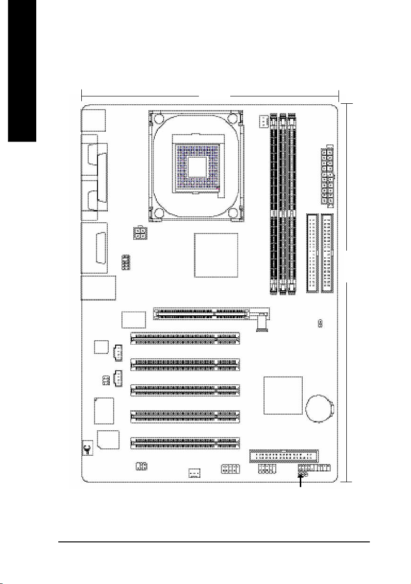
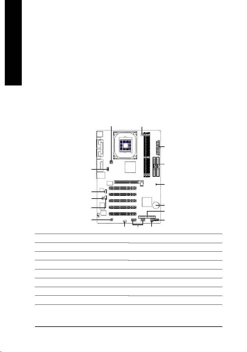
8S648-RZ Series Motherboard Layout
English
KB_MS
COMA
COMB
LINE_OUT
LINE_IN
MIC_IN
USB_L AN *
CODEC
SUR_CEN
#
LPT
GAME
IT8705
BIOS
F_AU DIO
ICS 1 883 *
CD _IN
AUX_IN
P4 Titan
SPDIF_IO
ATX_12 V
AGP 8X
SYS _FAN
SOC KET478
21 cm
SiS 6 48
VRM10.0
F_U SB2
CPU_FAN
Hyper Threading
Support
8S648-RZ
DDR1
AGP
PCI1
PCI2
PCI3
PCI4
PCI5
SiS 963L
F_U SB1
DDR2
FD D
ATX
IDE2
29.5 cm
IDE1
DDR3
CLR_ CM OS
BAT
F_PANEL
PWR_ LED
"*" Only for 8S648-RZ.
"#" Only for 8S648-RZ-C.
- 6 -8S648-RZ Series Motherboard
Page 7
English
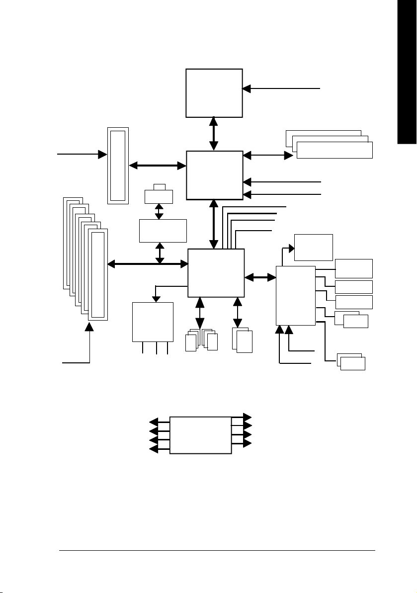
Block Diagram
AGPC LK
(66MHz)
5 P CI
PCICL K
(33MHz)
AGP 4X/ 8X
RJ45 *
ICS 1883 *
AC97 Li nk
AC97
CODE C
MIC
LINE-IN
6 U SB
LINE-OUT
Pentium 4
Socket 478
CP U
SiS 648
SiS 963L
ATA33/66/100/133
Ports
CPUCLK+/- (1 00/133 MHz)
System Bus
400/533 MHz
266/333 MHz
48 MHz
LPC BUS
IDE Channels
ZCLK (66/133M Hz)
HCLK+/- (100/133MHz)
66/133 MHz
33 MHz
14.318 MHz
BIOS
IT8705
24 MHz
33 MHz
DDR
Game Port
Flop py
LPT Port
PS/2
KB/M ouse
COM
Por ts
PCICLK (33M Hz)
USBCLK (48 MHz)
"*" Only for 8S648-RZ.
14.318 MHz
33 MHz
CLK GEN
- 7 -
ZCLK (66/133M Hz)
CPUCLK+/- ( 100/133M Hz)
AGPCLK (66M Hz)
HCLK+/- (100/133MHz)
Introduction
Page 8
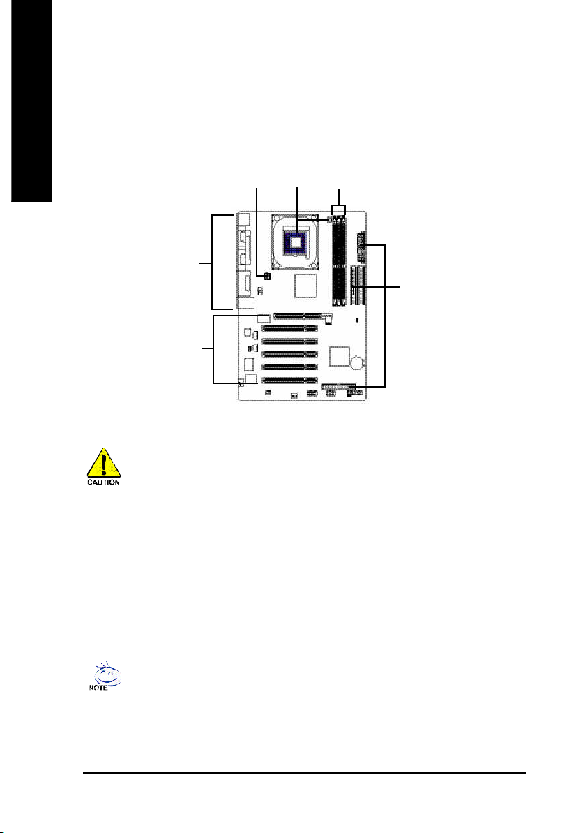
Hardware Installation Process
To s et up your co mp uter, you mus t co mpl ete the following steps:
English
Step 1- Install the Central P rocess ing Unit (CP U)
Step 2- Install mem ory modules
Step 3- Install e xpansi on car ds
Step 4- Install I/O Pe riphera ls Cabl es
Step 4
Step 1
Step 2
Step 4
Step 4
Step 3
Step 1: Install the Central Processing Unit (CPU)
Before i nstalling the p rocess or, adh ere to the following warning:
1. Pleas e m ake sure the CPU type i s supp orted by the m otherboard.
2. The p rocess or will over heat without the he atsink an d/or fan, resul ting i n perm anent
irreparable dam age.
3. If you do not match the CP U socke t Pin 1 and CPU cut edge well, it will caus e im proper
installation. Please change the in sert orientation.
4. Apply therma l grea se between the proce ssor a nd cooling fan.
5. Never run the pro cessor without the he atsink p roperl y and firmly attached . Perm anent
dam age will resul t.
6. Pleas e set the CPU hos t frequency in accorda nce with your pr ocessor 's spe cifications.
We don' t recomm end you to set the system bus frequency over the CPU's specification
becau se these specific bus frequenc ies are no t the standard specifica tions for CPU,
chipset and mos t of the periphe rals. Wh ether your s ystem ca n ru n under these specific
bus freq uencies pr operly will depe nd on your hardware configura tions, includ ing CP U,
Me mo ry, Card s… etc.
HT fu nctio nality re quir ement c ontent :
Ena bl ing the fun ctio nal ity of H yp er- Thr ea din g Techn ol ogy for your c om puter system
requir es all o f the following pla tform com ponents:
- CP U: An Intel® Pen tium 4 Proce ssor with HT Techno logy
- Chi pset: An SiS® Chi pset that suppo rts H T Technolo gy
- BIOS: A BIOS that su pports HT Technol ogy an d has it enabled
- OS: An op eration s ystem that has optim izations for HT Techn ology
- 8 -8S648-RZ Series Motherboard
Page 9
English
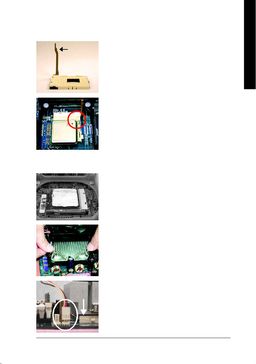
Step 1-1: CPU Installation
Socket
Actuation
Lever
Figure 1.
Pull the r od to the 9 0-degree directly.
Figure 2.
Locate Pin 1 in the s ocket an d loo k for a (golde n) cu t edge on the
CPU up per corn er. Insert the C PU into the soc ket. (Do not force the
CPU i nto the sock et.) Then mov e the s ock et l eve r to the locke d
position while ho lding pressure on the c enter of the CPU.
Step 1-2: CPU Cooling Fan Installation
Figure 1.
Apply the therm al tape(or grease) to provide better heat conduction
between you r CP U a nd c oolin g fan.
Figure 2.
Fasten the coo ling fan suppor ting-base o nto the CPU socket on the
motherboard.
Figure 3.
Ma ke sur e the CPU fan is plugg ed to the CPU fan co nnector, than
install c omp lete.
- 9 - Har dware Installation Process
Page 10
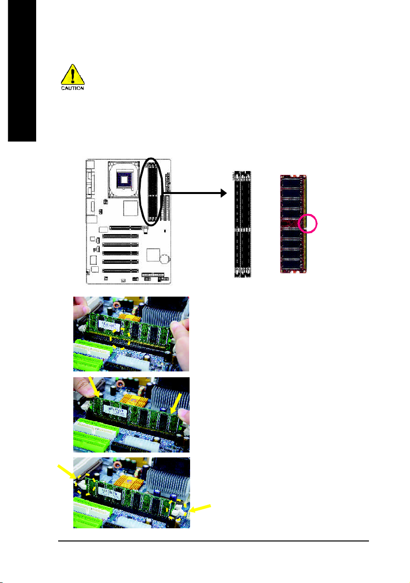
Step 2: Install Memory Modules
English
The mother boar d ha s 3 du al inl ine mem ory m odul e (DIM M) s ocke ts. Th e BIOS wil l autom atica lly
detects me mo ry type and siz e. To instal l the mem ory mo dule , just p ush it ve rtical ly into the DIMM
socket. The DIM M m odule can only fit in one direction due to the notch. Mem ory size c an vary between
soc ke ts.
Before i nstalling the m emory modules, adhere to the following warning:
1. Please note that the DIMM m odule can onl y fit in one di rection due to the one notch.
Wrong o rientation will cause im proper installation. Please change the insert orientation.
Notch
DDR
1. The DIMM sock et has a notch, so the DIM M
me mor y mo dule can o nly fit in one d irection.
2. Insert the DIMM m em ory m odule ver tically in to
the DIM M soc ket. The n pus h i t down.
3. Close the pl astic c lip at both e dges of the DIMM
sockets to lo ck the DIMM m odule.
Reve rse the installation steps when yo u wish to
rem ove the DIMM modu le.
- 10 -8S648-RZ Series Motherboard
Page 11
English
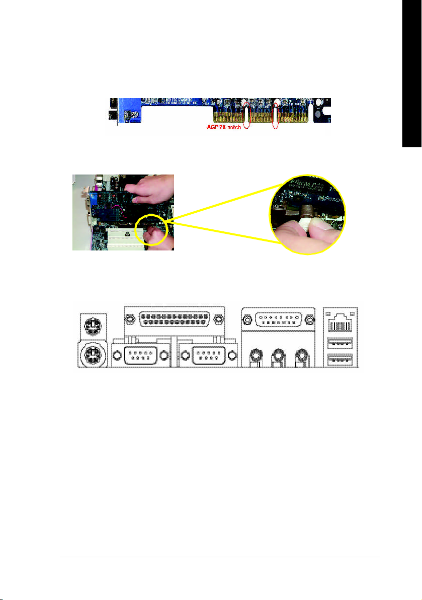
Step 3: Install AGP Card
1. Read the relateAGP card's instruction document before install the AGP card into the computer.
2. If your AGP card has "AGP 8X/4X(1.5V) notch" (show below), please m ake sure your AGP card is AGP
8X/4X(1.5V).
AGP 4X/8X notch
3. Plea se car efully pull out the small white- drawabl e bar at the end of the AG P slot when you try to
install/ U ninstall the AGP ca rd. Ple ase alig n the AGP card to the onboard AGP slot and pr ess firm ly
down on the slot .M ake s ure you r AGP card is lock ed by the small white- drawab le ba r.
Step 4: Install I/O Peripherals Cables
Step 4-1: I/O Back Panel Introduction
u
v
w
y
} *
x
{
z
|
~
u PS/2 Keyboard and PS/2 Mouse connector
This connec tor supp orts s tandard P S/2 ke yboard and PS/2 m ouse.
v Parallel port (LPT)
Devic e like printer can b e conne cted to Pa rallel port.
w/x Serial port (COMA/COMB)
Mo use and mode m e tc. can be conn ected to Serial port.
y Game/MIDI port
This conne ctor s uppor ts joystick, M IDI keyboard and other relate audio devices.
z Line Out jack
Connec t the stereo speak ers or earphone to this c onnector.
{ Line In jack
Devi ces l ike CD-R OM , walkm an etc. can be connect to Line In jack.
"*" Only for 8S648-RZ.
- 11 - Hardware Installation Proc ess
Page 12
| MIC In jack
English
} LAN port *
~ USB port
Step 4-2: Connectors Introduction
Mi crophon e can be c onnect to M IC In jac k.
After installation of the audio driver, you are able to use 2 /4/6-channel audio feature by software
selection . You can connect "Fron t speaker" to "Li ne Out" ja ck, Con nect " Rear sp eaker" to
"Line In" jack an d conn ect "Center /Subwoofer" to "M IC In" jac k.
LAN is fast Ethernet with 10/10 0M bps sp eed.
Before you conn ect you r d evice (s) i nto USB connector( s), p lease m ake sure yo ur de vice( s)
such as USB k eyboa rd, m ous e, scann er, zi p, sp eaker. ..etc. Have a stand ard USB interface.
Also m ake sure your OS supports USB controller. If your OS does not support USB controller,
please contact OS ve ndor for possi ble patch o r drive r upgra de. For m ore i nformation please
contact y our OS or dev ice( s) ven dors .
1
3
2
1) ATX_12V
2) ATX
3) CPU_FAN
4) SYS_FAN
5) IDE1 / IDE2
6) FDD
7) PWR_LED
8) F_PANEL
"*" Only for 8S648-RZ.
9
11
10
12
13
4
14
5
15
16
6
8
7
9) F_AUDIO
10) SUR_CEN
11) CD_IN
12) AUX_IN
13) SPDIF_IO
14) F_USB1 / F_USB2
15) CLR_CMOS
16) BAT
- 12 -8S648-RZ Series Motherboard
Page 13

English
1) ATX_12V (+12V Power Connector)
This c onnector ( ATX_12V) supp lies the C PU oper ation voltage (V core).
If this "ATX_1 2V con nector" i s no t connected, system c annot boo t.
Pin No. Definition
3
1
4
2
1 GND
2 GND
3 +12V
4 +12V
2) ATX (ATX Power)
AC p ower cord shou ld onl y be connected to you r power s upply u nit after ATX power cab le a nd
other rela ted devices are firm ly connec ted to the main board.
10
Pin No. Definition
1 3.3V
20
2 3.3V
3 GND
4 VCC
5 GND
6 VCC
7 GND
8 Power Good
11
1
9 5V SB (stand by +5V)
10 +12V
Pin No. Definition
11 3.3V
12 -12V
13 GND
14 PS_ON(soft on/off)
15 GND
16 GND
17 GND
18 -5V
19 VCC
20 VCC
3) CPU_FAN (CPU Fan Connector)
Pleas e note, a proper ins tallation of the CPU coo ler is essential to pre vent the CPU from runni ng
unde r abn orm al con dition or dam age d by overh eating . T he C PU fan con nector supports Ma x.
current up to 600 m A.
Pin No. Definition
1 GND
1
2 +12V
3 Sense
- 13 - Hardware Installation Proc ess
Page 14
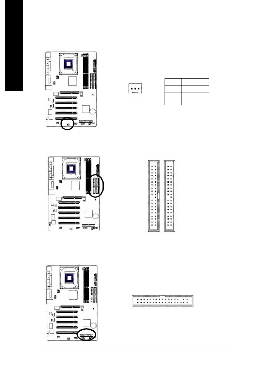
4) SYS_FAN (System Fan Connector)
English
5) IDE1 / IDE2 (IDE1 / IDE2 Connector)
Thi s conn ector allo ws y ou to l ink with the c ool ing fan on the s ystem cas e to lower the sys tem
temperature.
Pin No. Definition
1
Impor tant Notice: Please c onnec t first har d dis k to IDE 1 and conne ct CD -ROM to IDE2. The red
stripe o f the ribb on cab le m ust be the sam e side with the Pin1.
1 GND
2 +12V
3 Sense
40
IDE2
2
39
IDE1
1
6) FDD (Floppy Connector)
Pleas e conne ct the floppy drive ribbon cab les to FD D. It supp orts 360K, 1.2M , 720 K, 1.44M and
2.8 8M bytes flo ppy disk typ es.
The r ed stripe of the ri bbon ca ble m ust be the sam e side with the Pin1.
33
34
1
2
- 14 -8S648-RZ Series Motherboard
Page 15

English
7) PWR_LED
PWR_ LED is con nect with the system power indica tor to ind icate whether the sys tem is on/ off.
It will bl ink when the system enters susp end m ode. If yo u use du al color LED, p ower LED will turn
to another colo r.
Pin No. Definition
1
1 MPD+
2 MPD-
3 MPD-
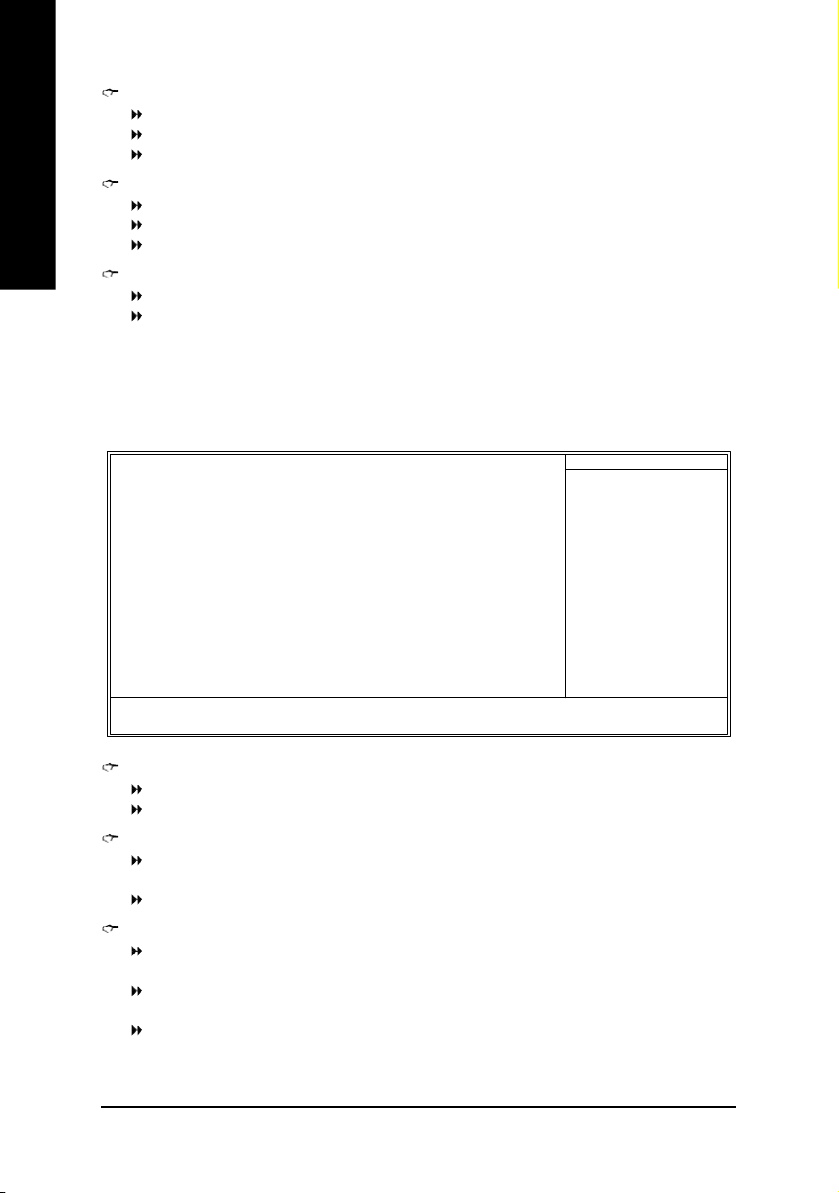
8) F_PANEL (2 x 10 pins Connector)
Please c onnect the power LED, PC speaker, r eset switch and power switch etc of your chas sisfront
panel to the F _PANEL connec tor accor ding to the pin assignm ent belo w.
Sof t Po wer
Connect or
SPEAK+
1
Res et Swi tch
Speak er Co nnector
SPEAK-
20
19
Messa ge L ED/
Po wer/
Slee p LED
IDE H ard Disk Acti ve LE D
PW+
MSG+
PW-
MSG-
1
1
1 2
1
1
HD-
RES+
NC
HD+
RES-
HD (IDE Hard Disk Active LED) Pin 1: LED anode(+)
Pin 2: LED cathode(-)
SPK (Speaker Connector) Pin 1: VCC(+)
Pin 2- Pin 3: NC
Pin 4: Data(-)
RES (Reset Switch) Open: Normal Operation
Close: Reset Hardware System
PW (Soft Power Connector) Open: Normal Operation
Close: Power On/Off
MSG (Message LED/ Power/ Sleep LED) Pin 1: LED anode(+)
Pin 2: LED cathode(-)
NC NC
- 15 - Hardware Installation Proc ess
Page 16

9) F_AUDIO (Front Audio Connector)
English
10) SUR_CEN (Surround Center Connector)
If you want to use Front Au dio c onnector , you must rem ove 5-6, 9-10 Jumper.
In order to utilize the front audio header, your chassis must have front audio connector. Also pl ease
mak e sure the pin as sigme nt on the cable is the sam e as the pin assigm ent on the MB h eader. To
find ou t if the ch assis you are buying s upport fron t audio connector, please contact your deale r.
Plea se no te, y ou ca n have the a lternativ e of usi ng front aud io conn ector o r of using r ear a udio
conn ector to play soun d.
Pin No. Definition
1 MIC
2 GND
3 REF
10 9
12
4 Power
5 Front Audio (R)
6 Rear Audio (R)
7 Reserved
8 No Pin
9 Front Audio (L)
10 Rear Audio (L)
Pleas e contact your neare st dealer for o ptional SUR_CEN c able.
Pin No. Definition
56
1
2
1 SUR OUTL
2 SUR OUTR
3 GND
4 No Pin
5 CENTER_OUT
6 BASS_OUT
11) CD_IN (CD In Connector)
Connec t CD-ROM or DVD -ROM audio out to the conn ector.
1
- 16 -8S648-RZ Series Motherboard
Pin No. Definition
1 CD-L
2 GND
3 GND
4 CD-R
Page 17

English
12) AUX_IN (AUX In Connector)
Connect other devi ce(such as PCI TV Tunner au dio out)to the connector.
Pin No. Definition
1
1 AUX-L
2 GND
3 GND
4 AUX-R
13) SPDIF_IO (SPDIF In/Out Connector)
The S PDIF o utput is cap able o f prov iding digital audio to extern al spe akers or com presse d AC3
data to an e xterna l Do lby Digital Deco der. U se thi s feature only whe n yo ur stere o sy stem h as
dig ital i np ut functi on. B e ca refu l with the pol ar ity of the SPDIF _IO co nne ctor. Che ck the pin
assig nmen t carefully while y ou con nect the SPDIF cabl e, inco rrect con nection be tween the cab le
and co nnector will m ake the dev ice una ble to work or eve n dam age it. F or o ptional SPD IF cable,
pleas e con tact your loc al dea ler.
Pin No. Definition
2
6
1
5
1 VCC
2 No Pin
3 SPDIF
4 SPDIFI
5 GND
6 GND
- 17 - Hardware Installation Proc ess
Page 18

14) F_USB1 / F_USB2 (Front USB Connector)
English
15) CLR_CMOS (Clear CMOS)
Be ca reful with the pol arity of the front USB c onnector . Chec k the pin assign me nt car efully whi le
you con nect the front USB c able, in correct conne ction between the cable and connector will m ake
the dev ice unab le to work or even dam age i t. Fo r option al front USB cable, plea se contact yo ur
local d ealer.
Pin No. Definition
1 Power
2 Power
3 USB DX-
2 10
1
9
4 USB Dy-
5 USB DX+
6 USB Dy+
7 GND
8 GND
9 No Pin
10 NC
You m ay clea r the C MOS da ta to i ts default va lues by this ju mp er. To clea r CMO S, tem pora rily
shor 1- 2 pin. D efault doesn't includ e the "Shunter" to preven t from im proper u se this jum per.
1
Open: Norm al
16) BAT (BATTERY)
1
Short: Clear CMOS
CAUTION
Danger of explosion if battery is incorrectly replaced.
Replace only with the same or equivalent type
recomm ended by the manufacturer.
+
Dispose of used batteries according to the
manufacturer's instructions.
If you want to erase CMOS...
1. Turn OFF the computer and unplug the power cord.
2. Remove the battery, wait for 30 second.
3. Re-install the battery.
4. Plug the power cord and turn ON the com puter.
- 18 -8S648-RZ Series Motherboard
Page 19

Chapter 2 BIOS Setup
BIOS Se tup is an ov ervie w of the BIOS Setup Progr am. Th e prog ram that al lows use rs to mod ify the
basic system co nfiguration. This type of inform ation is stored in battery-backed CMOS RAM so that it
retains the Setup informa tion when the po wer is turned off.
ENTERING SETUP
Powering ON the com puter and pressing <Del> immediately will allow you to enter Setup. If you require
mo re adva nced BIOS s ettings , pl ease go to "Advanc ed BIOS" se tting m enu. To enter Advanced BIOS
setting m enu, press "C trl+F1" k ey on the BIOS sc reen.
CONTROL KEYS
< > < >< >< > Mo ve to sele ct item
<Enter> Select Item
<Esc > Ma in M enu - Q uit an d not save changes into CM OS Status Page S etup Me nu
and Option Page Setup M enu - Exit cur rent page and return to Ma in M enu
<+/P gUp> Increase the num eric value or make chang es
<-/PgDn> Decrea se the num eric value or make changes
<F1> General help, o nly for Status Pa ge Setup M enu and Option Page Setup M enu
<F2> Item Help
<F5> Restore the previous CM OS value from CMOS, only for Option Page Setup Menu
<F6> Load the file- safe de fault CMOS value from B IOS default table
<F7> Load the Op timized D efaults
<F8> Q-Fl ash utili ty
<F9> System Inform ation
<F10> Save all the CM OS ch anges , o nly for M ain M enu
Main Menu
The on -line d escription of the hig hlighted s etup function is disp layed a t the b ottom o f the s creen.
Status Page Setup Menu / Option Page Setup Menu
Press F1 to pop up a sm all h elp window that desc ribes the a ppropr iate key s to u se and the possib le
selec tions for the high lighted i tem. T o e xit the Help Windo w pres s <Esc >.
English
The Main Menu (For example: BIOS Ver. : F7d)
Once you enter Award BIOS CM OS Setup U tility, the Ma in M enu ( as figure be low) will ap pear on the
scr een. T he M ain Menu allows you to select from eight setup functions and two exit choices. Use
arrow ke ys to s elect am ong the items and press <Enter> to a ccept or enter the s ub-m enu.
CMOS Setu p Utili ty-Co pyrig ht (C ) 198 4-200 4 Award Soft ware
} St anda rd CM OS Feat ures
} Ad vanc ed BI OS Feat ures
} In tegr ated Per iphe rals
} Po wer Manag ement S etup
} Pn P/PC I Co nfig urat ions
} PC Heal th Stat us
} Fr equen cy/V oltag e C ontr ol
ESC: Qu it higf: Select Item
F8: Q-Fla sh F10: Save & Exit Set up
Time , Dat e, Har d Disk Type. ..
Top Perf orma nce
Load Fail -Safe D efaul ts
Load Opti mized D efaul ts
Set Super visor P asswo rd
Set U ser Pass word
Save & Exit S etup
Exit Witho ut Savi ng
- 19 - BIOS Setup
Page 20

If you can't find the setting you want, please press "Ctrl+F1" to search the advanced
option hidden.
English
• Standard CMOS Features
• Advanced BIOS Features
• Integrated Peripherals
• Power Management Setup
• PnP/PCI Configuration
• PC Health Status
• Frequency/Voltage Control
• Top Performance
• Load Fail-Safe Defaults
• Load Optimized Defaults
• Set Supervisor Password
• Set User Password
• Save & Exit Setup
• Exit Without Saving
This s etup page includes al l the item s in standard com patible BIOS.
This setup page i nclude s all the item s of Award specia l e nhance d features.
This se tup page incl udes all onbo ard perip herals.
This s etup page incl udes all the items of Gree n function features.
This setup pag e i nclude s all the configu rations of PCI & P nP ISA resou rces.
This setup p age is the System a uto detect Tem perature, voltage, fan, s peed.
This setup page is co ntrol CPU clock and freque ncy ra tio.
If you wish to m axim ize the p erform ance of you r sys tem, set "Top Pe rforma nce" as "Enab led".
Fail-Sa fe Defaults indicates the value of the sys tem param eters which the system would be in s afe
configuration.
Optim ized Defaults indi cates the value of the system p aram eters which the sys tem woul d b e in
best performa nce configuration.
Chan ge, s et, o r dis able password. It allows you to li mi t access to the system and Setup, or just
to Setup.
Chan ge, set, or d isab le pass word. It allo ws you to l im it ac cess to the sys tem.
Save CM OS val ue se ttings to CM OS an d exit se tup.
Aband on al l C MOS value chan ges an d e xit setup.
- 20 -8S648-RZ Series Motherboard
Page 21

Standard CMOS Features
CMOS Setu p Utili ty-Co pyrig ht (C ) 198 4-200 4 Award Soft ware
Date (mm :dd: yy) Fri, Jan 9 2004
Time (hh :mm: ss) 22: 31:2 4
} IDE Pri mary Ma ster [No ne]
} IDE Pri mary Sla ve [No ne]
} IDE Sec ondary M aster [No ne]
} IDE Sec ondar y S lave [No ne]
Driv e A [1.4 4M, 3 .5"]
Driv e B [No ne]
Flopp y 3 Mode Supo rt [Disab led]
Holt On [All , But Ke yboar d]
Base Memo ry 640K
Exte nded Mem ory 127M
Tota l Me mory 128M
higf: Mov e En ter: Sele ct +/ -/PU /PD: Val ue F10: Sa ve ESC: Ex it F1: Gener al Help
F5: Previo us Valu es F6: F ail-Sa ve Defau lt F7: Optim ized De faul ts
Date
The d ate form at is <week>, <month>, <day>, <year>.
Week The week, from Sun to Sat, d eterm ined by the BIOS and is displ ay on ly
Month Th e mo nth, Jan. Throug h Dec.
Day The day, from 1 to 31 ( or the max imu m al lowed in the m onth)
Year The year, from 1999 through 2098
Time
The tim es format in <hour> <minute> <second>. The time is calculated base on the 24-hour
mi litary-tim e clock. For example, 1 p.m. is 13:00:00.
IDE Primary Master, Slave / IDE Secondary Master, Slave
The c ategor y i dentifie s the typ es of har d di sk from drive C to F that has been installed in the
com puter. The re are two types: auto type, and ma nual type. Man ual type i s us er-definab le; Auto type
which will autom atical ly detect H DD type.
Note that the spec ifications of y our d rive m ust match with the drive table. The hard disk will not work
proper ly if you enter impr oper i nformation for this category.
If you select User Type, related information will be asked to enter to the following items. Enter the information
directly from the keyboard and press <Enter>. Such inform ation shoul d be provi ded in the doc umen tation form your hard disk vendor or the system m anufacturer.
Cyli nder Num ber o f cyli nders
Head Num ber of hea ds
Precom p Write precomp
Landing Zone Lan ding zone
Sector Num ber of sectors
If a hard disk has no t been installe d, sel ect NONE a nd press <Enter>.
Stan dard CMOS Fe atur es
Item He lp
Menu Leve l}
Chan ge th e day, mont h,
year
<We ek>
Sun. to Sat.
<Mon th>
Jan. to Dec.
<Day>
1 to 31 (or maxim um
allow ed in th e mont h)
<Ye ar>
1999 to 2098
English
- 21 - BIOS Setup
Page 22

com puter.
English
Drive A / Drive B
The categor y iden tifies the types of flo ppy disk drive A or drive B that h as been ins talled in the
None No flo ppy drive i nstall ed
360K, 5. 25" 5.25 i nch PC-type s tandar d d rive ; 36 0K byte c apac ity.
1.2M , 5.25" 5.25 inch A T-type high- densi ty dr ive; 1.2M byte capacity
(3.5 inch when 3 M ode is En abled ).
720K, 3 .5" 3. 5 inc h double -side d dri ve; 7 20K byte c apaci ty
1.44M , 3.5" 3.5 inch double-s ided drive ; 1.4 4M byte capac ity.
2.88M , 3.5" 3.5 inch double-s ided drive ; 2.8 8M byte capac ity.
Floppy 3 Mode Support (for Japan Area)
Disabled No rma l Flo ppy D rive. (Default valu e)
Driv e A Driv e A is 3 m ode Floppy Driv e.
Driv e B Driv e B is 3 m ode Floppy Driv e.
Both Driv e A & B are 3 mod e Flopp y Dri ves.
Halt on
The c ategory determ ines whether the co mpu ter will s top if an error is de tected durin g p ower up.
No Erro rs The s ystem boot will not stop for any error that m ay be detected and y ou
will be pr omp ted.
All Err ors Wh enever the BIOS detects a non-fatal error the sy stem will b e stoppe d.
All, But K eyboa rd Th e sys tem boot will not s top for a keyboard error ; it will stop for al l other
errors. (Default value)
All, But Dis kette The system boot will not stop for a disk er ror; it will stop for all other errors.
All , Bu t D isk/ Key Th e system boot will not stop for a keyb oard or dis k error; it will stop for a ll
other errors.
Memory
The categor y is di splay -onl y whi ch is determ ined by POST (Power On Self Test) of the BIOS.
Base Memory
The POS T of the BIOS will d etermine the amo unt of base (or conv entional) m em ory ins talled
in the s ystem .
The v alue of the base me mor y i s typical ly 512K for s ystems with 512K m emory installed on
the motherboard, or 640K for systems with 640K or more mem ory installed on the motherboard.
Extended Memory
The B IOS de termin es how m uch extended m em ory i s pres ent durin g the POST.
This is the am ount of m em ory located above 1 M B i n the CPU 's m em ory addr ess m ap.
- 22 -8S648-RZ Series Motherboard
Page 23

Advanced BIOS Features
CMOS Setu p Utili ty-Co pyrig ht (C ) 198 4-200 4 Award Soft ware
Fir st Boot Devi ce [Fl oppy ]
Sec ond Boot Devi ce [HDD -0]
Thi rd Boot Devi ce [CDR OM]
Boot Up Flop py Se ek [Dis able d]
Pas sword C heck [Set up]
CPU Hype r-Thr eadin g
Ini t D ispla y Fir st [AGP]
higf: Mov e En ter: Sele ct +/ -/PU /PD: Val ue F10: Sa ve ESC: Ex it F1: Gener al Help
F5: Previo us Valu es F6: F ail-Sa ve Defau lt F7: Optim ized De faul ts
#
" # " System wil l detec t autom atica lly a nd sh ow up when you install the Intel® Pentiu m® 4
proc esso r with HT Te chno logy.
First / Second / Third Boot Device
Flo ppy Sele ct you r boot d evic e prio rity b y Flop py.
LS120 Sele ct your b oot dev ice priority b y LS12 0.
HDD-0~3 Select yo ur boot de vice p riori ty by HDD- 0~3.
SCSI Sele ct you r boot d evice p rior ity by S CSI.
CDROM Se lect y our boot devi ce pri ority b y CDRO M.
ZIP Sele ct you r boot de vice p riori ty by ZIP.
USB-FDD Sele ct your b oot dev ice priority by USB- FDD.
USB- ZIP Select y our boot dev ice priori ty by USB-ZIP.
USB-C DROM Se lect y our boot devi ce pri ority b y USB- CDRO M.
USB-HDD Select yo ur boot d evice pr iori ty by USB- HDD.
LAN Sele ct you r boot de vice p riori ty by LAN.
Disabled Se lect yo ur boot de vice priority b y Disab led.
Boot Up Floppy Seek
Durin g POST , B IOS will de termin e the floppy di sk dr ive installe d is 4 0 o r 80 trac ks. 3 60K type is
40 tracks 720K, 1. 2M and 1.4 4M are all 80 tracks.
Enabled BIOS sear ches for floppy di sk driv e to determ ine it is 40 or 80 tracks. Note that
BIOS can not tell from 7 20K, 1.2M or 1.4 4M drive type as they are all 80 tracks.
Disabled BIOS will not search for the type of floppy disk drive by track number. N ote that
there will not be any warning message if the drive installed is 360K. (Default value)
Password Check
Sy stem The system can not boot and can n ot access to Setup pa ge will b e denied if the
Setup Th e system will b oot, but access to Setup will b e denie d if the co rrect password
corre ct password is n ot entered at the prom pt.
is not entered at the prom pt. (Default valu e)
Adva nced BIOS Fe atur es
[Ena bled ]
Item He lp
Menu Leve l}
Sele ct Bo ot Devi ce
pri orit y
[Fl oppy ]
Boot from fl oppy
[LS1 20]
Boot from L S120
[HDD -0]
Boot from Fi rst H DD
[HDD -1]
Boot from Sec ond H DD
English
- 23 - BIOS Setup
Page 24

English
Integrated Peripherals
"*" Only for 8S648-RZ.
CPU Hyper-Threading
Enabled Enables CPU Hyper Threading Feature. Please note that this feature is only working
for operating system with multi processors mode supported. (Default value)
Disabled Di sables CPU Hyper Thr eadin g.
Init Display First
Selec t the first initation of moni tor or displa y from AGP o r P CI VGA car d.
AGP Se t Init dis play fir st to AGP. (Default valu e)
PCI Set Init di splay first to PCI.
CMOS Setu p Utili ty-Co pyrig ht (C ) 198 4-200 4 Award Soft ware
IDE1 Condu ctor Cab le [Auto ]
IDE2 Condu ctor Cab le [Auto ]
On-C hip P rimar y PCI I DE [Ena bled ]
On-C hip S econd ary PCI IDE [Enabl ed]
AC97 Aud io [Ena bled ]
Onbo ard L AN devi ce
USB Co ntro ller [Ena bled ]
USB Legac y Suppo rt [Disab led]
Onboa rd Ser ial Port 1 [3F8 /IRQ 4]
Onboa rd Ser ial Port 2 [2F8 /IRQ 3]
Onboa rd Par allel Po rt [378 /IRQ 7]
Para llel Port Mo de [SPP]
x ECP Mode Use DMA 3
Game Port Add ress [20 1]
Midi Port Add ress [33 0]
Midi Port IRQ [10]
higf: Mov e En ter: Sele ct +/ -/PU /PD: Val ue F10: Sa ve ESC: Ex it F1: Gener al Help
F5: Previo us Valu es F6: F ail-Sa ve Defau lt F7: Optim ized De faul ts
*
Inte grat ed P erip hera ls
[Ena bled ]
Item He lp
Menu Leve l}
[Au to]
Auto -det ect IDE
cabl e ty pe
[ATA 66/1 00/1 33]
Set Conduc tor cab le
to A TA66 /100/ 133( 80
-pi ns)
[ATA 33]
Set Conduc tor cab le
to A TA33( 40-p ins)
IDE1 Conductor Cable
Auto Will be automa tically d etected by B IOS. ( Default valu e)
ATA66/1 00 Set IDE1 Conductor Cable to A TA66/10 0 ( Please mak e sure your IDE devi ce
and ca ble is compatible with ATA66/100 ).
ATA33 Set IDE1 Con ductor Cable to A TA33 (P lease make su re your IDE d evice a nd
cable is com patible with ATA33 ).
IDE2 Conductor Cable
Auto Wi ll be automaticall y detected b y BIOS. (Defaul t value)
ATA66/1 00 Set IDE2 Conductor Cable to A TA66/10 0 ( Please mak e sure your IDE devi ce
and ca ble is compatible with ATA66/100 ).
ATA33 Set IDE2 Con ductor Cable to A TA33 (P lease make su re your IDE d evice a nd
cable is com patible with ATA33 ).
On-Chip Primary PCI IDE
Enabled Enable onboard 1st channel IDE por t. (Default value)
Disabled Dis able onbo ard 1st c hannel IDE po rt.
On-Chip Secondary PCI IDE
Enabled Enable onboard 2n d channel IDE port. (De fault value)
Disabled Dis able onbo ard 2nd c hannel IDE po rt.
- 24 -8S648-RZ Series Motherboard
Page 25

AC97 Audio
Enabled Enable onboard AC'97 a udio function. (Default valu e)
Disabled Di sable this function.
On Board LAN device *
Disabled Di sable this function.
Enabled Enable Onboar d Lan C hip device. (Default valu e)
USB Controller
Enabled Enable USB C ontroller. (De fault value)
Disabled Di sable USB Con troller.
USB Legacy Support
When USB keybo ard or mou se is installed, p lease s et at Ena bled.
Enabled Enabl e USB keyboa rd or m ouse suppor t.
Disabled Di sable U SB keyboar d or m ouse support. (Default value)
Onboard Serial Port 1
Auto BIOS will autom atically setup the port 1 addr ess.
3F8/IRQ4 En able onb oard Ser ial port 1 a nd a ddress i s 3F8. ( Default value)
2F8/IRQ3 Ena ble onbo ard Seria l port 1 and addr ess is 2 F8.
3E8/IRQ4 Ena ble onbo ard Seria l port 1 and addr ess is 3 E8.
2E8/IRQ3 Ena ble onbo ard Seria l port 1 and addr ess is 2 E8.
Disabled Dis able onboa rd Serial port 1.
Onboard Serial Port 2
Auto BIOS will autom atically setup the port 2 addr ess.
3F8/IRQ4 Ena ble onbo ard Seria l port 2 and addr ess is 3 F8.
2F8/IRQ3 En able onb oard Ser ial port 2 a nd a ddress i s 2F8. ( Default value)
3E8/IRQ4 Ena ble onbo ard Seria l port 2 and addr ess is 3 E8.
2E8/IRQ3 Ena ble onbo ard Seria l port 2 and addr ess is 2 E8.
Disabled Dis able onboa rd Serial port 2.
Onboard Parallel port
378/IRQ7 Enable onboar d LPT port and address is 378/IRQ7. (D efault value)
278/IRQ5 Enable onboar d LPT p ort and address is 278 /IRQ5.
Disabled Dis able onb oard LPT port.
3BC/ IRQ7 Enable on board L PT por t and a ddress is 3BC /IRQ7.
Parallel Port Mode
SPP Using Para llel por t as Standa rd Paral lel Por t. (Default valu e)
EPP Using Par allel p ort as Enhance d Paral lel Por t.
ECP Using Parall el port as Ex tended Capabi lities Por t.
ECP+ EPP Using Para llel port as ECP & E PP m ode.
ECP Mode Use DMA
3 Set ECP Mod e U se DM A to 3 . ( Default valu e)
1 Set ECP M ode Use DM A to 1.
English
"*" Only for 8S648-RZ.
- 25 - BIOS Setup
Page 26
English
Power Management Setup
Game Port Address
201 Set Gam e P ort Address to 201. (Default valu e)
209 Set Gam e Port Addres s to 209.
Disabled Di sable this function.
Midi Port Address
300 Set Mi di Port Addres s to 300.
330 Set Mi di P ort Address to 330. (Default valu e)
Disabled Di sable this function.
Midi Port IRQ
5 Set M idi Por t IRQ to 5.
10 Se t Midi Port IRQ to 10. (De fault value)
CMOS Setu p Utili ty-Co pyrig ht (C ) 198 4-200 4 Award Soft ware
ACPI Suspe nd Type [S 1(PO S)]
Soft- Off b y P WR_BT TN [Of f]
Syste m Aft er AC Ba ck [Of f]
IRQ [ 3-7, 9-1 5], N MI [E nabl ed]
Mode mRing On [Ena bled ]
PME E vent Wak e Up [E nabl ed]
Power On by K eyboa rd [D isab led]
Power On by M ouse [D isab led]
Resu me by A larm [Disab led]
x Mont h Ala rm NA
x Day (of Mo nth) 0
x Time (hh :mm: ss) 0 0 0
Powe r Man agem ent Set up
Item He lp
Menu Leve l}
[S1]
Set suspen d type to
Powe r On Su spend und er
ACPI OS
[S3]
Set suspen d type to
Suspe nd to RA M und er
ACPI OS
higf: Mov e En ter: Sele ct +/ -/PU /PD: Val ue F10: Sa ve ESC: Ex it F1: Gener al Help
F5: Previo us Valu es F6: F ail-Sa ve Defau lt F7: Optim ized De faul ts
ACPI Suspend Type
S1(POS) Set ACP I susp end type to S 1. (Default v alue)
S3(ST R) Set ACPI susp end type to S3.
Soft-off by PWR-BTTN
Off The u ser pres s the po wer bu tton o nce, he can turn off the sy stem.
Suspend The us er pre ss the power button once , then he can enter susp end m ode.
(Default valu e)
System after AC Back
LastState Whe n AC-power b ack to the s ystem, the s ystem will r eturn to the Las t state
before AC-power off.
Off When AC-p ower back to the sys tem, the s ystem will be in "Off" state.
On Wh en A C-power b ack to the s ystem , the system will be i n "On" state.
(Default valu e)
- 26 -8S648-RZ Series Motherboard
Page 27

IRQ [3-7, 9-15], NMI
Disabled Di sable this function.
Enabled En able this function . (D efault value)
ModemRingOn
Disabled Dis able M odem Ring o n function.
Enabled Ena ble M odem Ring o n function. (Default value)
PME Event Wake Up
Disabled Di sable this function.
Enabled En able PM E a s wake up event. (De fault valu e)
Power On by Keyboard
Pas swor d Enter from 1 to 8 charac ters to set the key board power on pa ssword.
Disabled Di sabled this function. ( Default value)
An y Key S et K eybo ard powe r on by any k ey.
Power On by Mouse
Enabled En able Power On b y M ouse function.
Disabled Di sable this function. (D efault value)
Resume by Alarm
You c an set "Resu me by Alarm " item to ena bled and k ey in Data/time to po wer on system .
Disabled Dis able this function. (De fault Value)
Enabled En able a larm function to POW ER ON sy stem.
If RTC Alar m Lead To P ower On is Enable d.
Month Alar m : NA , 1~12
Day ( of M onth) : 0~31
Tim e ( hh: mm : ss) : (0~23) : (0~59) : (0~59)
English
- 27 - BIOS Setup
Page 28

PnP/PCI Configurations
English
CMOS Setu p Utili ty-Co pyrig ht (C ) 198 4-200 4 Award Soft ware
PCI 4 I RQ Ass ignme nt [ Auto ]
PCI 1/5 IRQ Assi gnme nt [ Auto ]
PCI 2 I RQ Ass ignme nt [ Auto ]
PCI 3 I RQ Ass ignme nt [ Auto ]
higf: Mov e En ter: Sele ct +/ -/PU /PD: Val ue F10: Sa ve ESC: Ex it F1: Gener al Help
F5: Previo us Valu es F6: F ail-Sa ve Defau lt F7: Optim ized De faul ts
PnP/ PCI Conf igur atio ns
Item He lp
Menu Leve l}
PCI 4 IRQ Assignment
Auto Auto ass ign IRQ to PCI 4. (D efault valu e)
3,4,5 ,7,9,10 ,11,12, 14,15 Se t IRQ 3,4 ,5,7,9 ,10,1 1,12,1 4,15 to PCI 4.
PCI 1/PCI 5 IRQ Assignment
Auto Auto ass ign IRQ to PCI 1/PC I 5. (Defau lt va lue)
3,4,5 ,7,9,10 ,11,12, 14,15 Se t IRQ 3, 4,5,7, 9,10, 11,12, 14,15 to PCI 1 /PCI 5.
PCI 2 IRQ Assignment
Auto Auto as sign IRQ to PCI 2. (D efault v alue)
3,4,5 ,7,9,10 ,11,12, 14,15 Se t IRQ 3,4 ,5,7,9 ,10,1 1,12,1 4,15 to PCI 2.
PCI 3 IRQ Assignment
Auto Auto as sign IRQ to PCI 3. (D efault v alue)
3,4,5 ,7,9,10 ,11,12, 14,15 Se t IRQ 3,4 ,5,7,9 ,10,1 1,12,1 4,15 to PCI 3.
- 28 -8S648-RZ Series Motherboard
Page 29

PC Health Status
CMOS Setu p Utili ty-Co pyrig ht (C ) 198 4-200 4 Award Soft ware
Vcore 1.54V
DDR 25V 2.5 44V
+3.3V 3.3 60V
+12V 11.92 V
Curr ent C PU Temp eratu re 41 ° C
Curre nt CPU F AN Spe ed 4440 R PM
Curr ent S YSTE M FAN S peed 0 RPM
higf: Mov e En ter: Sele ct +/ -/PU /PD: Val ue F10: Sa ve ESC: Ex it F1: Gener al Help
F5: Previo us Valu es F6: F ail-Sa ve Defau lt F7: Optim ized De faul ts
Current Voltage (V) Vcore / DDR25V / +3.3V / +12V
Detect sy stem 's voltage status autom atically.
Current CPU Temperature
Detect CPU temper ature autom atically.
Current CPU/SYSTEM FAN Speed (RPM)
Detect CPU /SYSTE M Fan speed status a utoma tically.
PC H ealth St atus
Item He lp
Menu Leve l}
English
- 29 - BIOS Setup
Page 30

Frequency/Voltage Control
English
CMOS Setu p Utili ty-Co pyrig ht (C ) 198 4-200 4 Award Soft ware
CPU Clock R atio [10X]
Line ar Fr eque ncy Con trol [Dis able d]
x CPU Clock ( MHz) 100
x DRAM Cloc k ( MHz) AUTO
AGP/P CI Clo ck Contr ol [AU TO]
x AGP Clock ( MHz) 66
x PCI Clock ( MHz) 33
AGP Voltag e Contr ol [ Norm al]
DRAM Volta ge Contr ol [ Norm al]
higf: Mov e En ter: Sele ct +/ -/PU /PD: Val ue F10: Sa ve ESC: Ex it F1: Gener al Help
F5: Previo us Valu es F6: F ail-Sa ve Defau lt F7: Optim ized De faul ts
Freq uency /Volt age Con trol
Item He lp
Menu Leve l}
CPU Clock Ratio
This setup option will au toma tically assi gn by C PU detectio n.
For W illam ette CPU:
8X~23X default: 14X
For C- Stepping P4:
8X,10X ~24X de fault: 15X
For No rthwood C PU:
12X~24 X default: 16X
The o ption will dis play "Locke d" and r ead on ly if the C PU ratio is not chan geabl e.
Linear Frequency Control
Disabled Di sable this function. (D efault value)
Enabled En able this function.
CPU Clock (MHz)
100M Hz ~ 355M Hz Set CPU H ost Clock from 10 0MH z to 35 5MH z.
If you u se FS B400 P entium 4 proce ssor, please s et "CPU C lock" to 10 0MH z.If you use F SB533
Pentium 4 proc essor , plea se set "C PU Clock " to 133M Hz. If you use FSB800 Pentium 4
proc essor , ple ase set "CP U Clo ck" to 200 MH z.
Incorr ect usin g it ma y cause your sys tem bro ken. For power End- User use onl y!
DRAM Clock (MHz)
Pleas e set D RAM Clock accord ing to your require men t.
If you use DDR2 66 DRA M m odule, please set "DRAM Clock(MHz)" to Auto or 266. If you use
DDR333 DRAM mo dule, please set "DRAM Clock (MHz )" to Au to or 333.
Incorr ect usin g it ma y cause your sys tem bro ken. For power End- User use onl y!
AGP/PCI Clock Control
AUTO Set AGP /PCI C lock Control to AUT O. (Default v alue)
Manual Se t AGP/PC I Clo ck Con trol to Ma nual.
- 30 -8S648-RZ Series Motherboard
Page 31

AGP Clock (MHz)
Pleas e set AGP Cl ock ac cordi ng to your r equire men t.
Incorr ect usin g it ma y cause your sys tem bro ken. For power End- User use onl y!
PCI Clock (MHz)
Pleas e set PCI Cloc k acc ording to y our re quire men t.
Incorr ect usin g it ma y cause your sys tem bro ken. For power End- User use onl y!
AGP Voltage Control
Norm al Set AGP V oltage Control to Nor mal. (Default valu e)
+0.1V Set AGP Vol tage C ontrol to + 0.1V.
DRAM Voltage Control
Norm al Set DRAM Vol tage Control to Norm al. (Default value)
+0.1V Set DRAM Voltage Control to +0.1 V.
Top Performance
CMOS Setu p Utili ty-Co pyrig ht (C ) 198 4-200 4 Award Soft ware
} St anda rd CM OS Feat ures
} Ad vanc ed BI OS Feat ures
} In tegr ated Per iphe rals
} Po wer Manag ement S etup
} Pn P/PC I Co nfig urat ions
} PC Heal th Stat us
} Fr equen cy/V oltag e C ontr ol
ESC: Qu it higf: Select Item
F8: Q-Fla sh F10: Save & Exit Set up
Top Perf orma nce
Disa bled. ..... ..... ..... .... ..... [n]
Enab led.. ..... ..... ..... .... ..... [ ]
hi: M ove ENTE R: Ac cept
ESC: Abo rt
Top Perf orma nce
Load Fail -Safe D efaul ts
Load Opti mized D efaul ts
Set Super visor P asswo rd
Set U ser Pass word
Save & Exit S etup
Exit Witho ut Savi ng
English
If you wish to m axim ize the p erform ance of you r sys tem, set "Top Pe rforma nce" as "Enab led".
Disabled Disable this function. (Default Value)
Enabled Enab le Top Perform ance function.
"Top P erform anc e" will i ncrea se H /W workin g spe ed. Differe nt system configuration (both H/W
com ponent and OS) will effect the result. For example, the sam e H/W configuration might not run
pro perl y with Wi ndows X P, but wo rks smoo thly with W ind ows NT. There fore, if your s ystem is not
perform enough, the reliability or stability problem will appear s ometim es, and we will r ecomm end you
disabl ing the option to avoid the proble m as m entioned above.
- 31 - BIOS Setup
Page 32

Load Fail-Safe Defaults
English
Fail-Sa fe defaults contain the mos t appr opriate v alues of the s ystem param eters that allow m inim um
system per forma nce.
Load Optimized Defaults
CMOS Setu p Utili ty-Co pyrig ht (C ) 198 4-200 4 Award Soft ware
} St anda rd CM OS Feat ures
} Ad vanc ed BI OS Feat ures
} In tegr ated Per iphe rals
} Po wer Manag ement S etup
} Pn P/PC I Co nfig urat ions
} PC Heal th Stat us
} Fr equen cy/V oltag e C ontr ol
ESC: Qu it higf: Select Item
F8: Q-Fla sh F10: Save & Exit Set up
Load Fail -Safe Def aults (Y /N)? N
Loa d Fail- Safe Defa ults
Load Opti mized Def aults (Y /N)? N
Load Opti mized D efaul ts
Top Perf orma nce
Load Fail -Safe D efaul ts
Load Opti mized D efaul ts
Set Super visor P asswo rd
Set U ser Pass word
Save & Exit S etup
Exit Witho ut Savi ng
Top Perf orma nce
Load Fail -Safe D efaul ts
Load Opti mized D efaul ts
Set Super visor P asswo rd
Set U ser Pass word
Save & Exit S etup
Exit Witho ut Savi ng
Selecting this field loads the factory defaults for BIOS and Chipset Features which the system automatically
detec ts.
- 32 -8S648-RZ Series Motherboard
Page 33

Set Supervisor/User Password
CMOS Setu p Utili ty-Co pyrig ht (C ) 198 4-200 4 Award Soft ware
} St anda rd CM OS Feat ures
} Ad vanc ed BI OS Feat ures
} In tegr ated Per iphe rals
} Po wer Manag ement S etup
} Pn P/PC I Co nfig urat ions
} PC Heal th Stat us
} Fr equen cy/V oltag e C ontr ol
ESC: Qu it higf: Select Item
F8: Q-Fla sh F10: Save & Exit Set up
Ente r Pa sswo rd:
Chan ge/Se t/Dis able Pass word
When you select this function, the following messa ge will appear at the center of the scree n to assist you
in c reating a passwor d.
Type the password, up to eight characters, and press <Enter>. You will be asked to confirm the password.
Type the pas sword again an d pre ss <Enter>. Y ou ma y also pr ess <Esc> to abort the selec tion and not
enter a p asswor d.
To disab le p ass word, j ust pre ss <Enter> when y ou are p rom pted to enter pa sswor d. A m essage
"PASS WORD DISABLED " will appe ar to confirm the passwor d bein g dis abled. On ce the pass word is
disa bled, the system will boot and y ou can enter Setup freely.
The BIOS Setup prog ram a llows y ou to spe cify two sepa rate pass words:
SUPER VISOR PAS SWORD an d a US ER PASSWO RD. W hen di sabled , a nyone may acce ss all BIOS
Setup progr am func tion. W hen enabled , the Sup ervis or p assword is req uired for enteri ng the BIOS
Setup progr am a nd having full co nfiguration fields, the U ser password is requi red to ac cess onl y basic
item s.
If you sele ct "Sys tem" at "P assword Chec k" in A dvanc e BIOS Fe atures Men u, you will be pr om pted
for the pass word eve ry tim e the sys tem i s r ebooted or any time y ou try to en ter Se tup M enu.
If you select "Setup" a t "Password Check" i n Advanc e BIOS Features Menu , you will be pr ompted o nly
when y ou try to enter Se tup.
Top Perf orma nce
Load Fail -Safe D efaul ts
Load Opti mized D efaul ts
Set Super visor P asswo rd
Set U ser Pass word
Save & Exit S etup
Exit Witho ut Savi ng
English
- 33 - BIOS Setup
Page 34

Save & Exit Setup
English
Type "Y" will qui t the S etup Utility and sav e the use r se tup v alue to R TC C MO S.
Type "N" wil l retur n to Setup Utility.
Exit Without Saving
CMOS Setu p Utili ty-Co pyrig ht (C ) 198 4-200 4 Award Soft ware
} St anda rd CM OS Feat ures
} Ad vanc ed BI OS Feat ures
} In tegr ated Per iphe rals
} Po wer Manag ement S etup
} Pn P/PC I Co nfig urat ions
} PC Heal th Stat us
} Fr equen cy/V oltag e C ontr ol
ESC: Qu it higf: Select Item
F8: Q-Fla sh F10: Save & Exit Set up
Save to CMOS a nd EX IT (Y/N)? Y
Sav e Dat a to CM OS
Quit With out S aving ( Y/N)? N
Aban don a ll Data
Top Perf orma nce
Load Fail -Safe D efaul ts
Load Opti mized D efaul ts
Set Super visor P asswo rd
Set U ser Pass word
Save & Exit S etup
Exit Witho ut Savi ng
Top Perf orma nce
Load Fail -Safe D efaul ts
Load Opti mized D efaul ts
Set Super visor P asswo rd
Set U ser Pass word
Save & Exit S etup
Exit Witho ut Savi ng
Typ e "Y" will qui t the Setup Utility withou t savi ng to RT C CM OS.
Type "N" wil l retur n to Setup Utility.
- 34 -8S648-RZ Series Motherboard
Page 35

Revision History
Chapter 3 Install Drivers
Install Drivers
Pictures below are shown in Windows XP
Insert the driver CD-title that came with your motherboard into your CD-ROM drive, the driver
CD-title will auto start and show the installation guide. If not, please double click the CD-ROM
device icon in "My computer", and execute the setup.exe.
INSTALL CHIPSET DRIVER
This page shows the drivers that need to be installed for the system. Click each item to install the driver
manually or switch to the to install the drivers automatically.
English
The "Xpress Install" uses the"Click and Go" technology to install the drivers automatically. Just select the
drivers you want then click the "GO" button. The will execute the installation for you by itself.
We recommend that you install all components in the list.
Massage: Some device drivers will restart your
system automatically. After restarting your system the
"Xpress Install" will continue to install other drivers.
Click "GO".
- 35 -
Driver Installation
Page 36

English
Item Description
n SIS AGP Driver
n USB Patch for WinXP
n SiS PCI Lan Driver *
n C-Media AC97 Audio Driver
n SIS USB 2.0 Driver
Driver install finished!! you have to reboot system!!
Install SIS AGP Driver.
This patch driver can help you to resolve the USB device wake up S3 hang up issue in XP.
For SiS series Lan driver.
Install C-Media AC97 audio driver.
It is recommended that you use the Microsoft Windows update for the most updated driver
for XP/2K.
"*" Only for 8S648-RZ.
- 36 -8S648-RZ Series Motherboard
Page 37

English
- 37 -
Memo
Page 38

English
- 38 -8S648-RZ Series Motherboard
Page 39

English
- 39 -
Memo
Page 40

CONTACT US
Contact us via the information in this page all over the world.
— Taiwan
English
Gigabyte Technology Co., Ltd.
Address: No.6, Bau Chiang Road, Hsin-Tien, Taipei Hsien,
Taiwan, R.O.C.
Tel: 886 (2) 8912-4888
Fax: 886 (2) 8912-4004
Tech. Support:
http://tw.giga-byte.com/TechSupport/ServiceCenter.htm
Non-Tech. Support (Sales/Marketing issues):
http://ggts.gigabyte.com.tw/nontech.asp
Website: http://www.gigabyte.com.tw
— USA
G.B.T. INC.
Address: 17358 Railroad St, City of Industry, CA 91748.
Tel: 1 (626) 854-9338
Fax: 1 (626) 854-9339
Tech. Support:
http://www.giga-byte.com/TechSupport/ServiceCenter.htm
Non-Tech. Support (Sales/Marketing issues):
http://ggts.gigabyte.com.tw/nontech.asp
Website: http://www.giga-byte.com
— Germany
G.B.T. Technology Trading GmbH
Tel: 49-40-2533040
49-01803-428468 (Tech.)
Fax: 49-40-25492343 (Sales)
49-01803-428329 (Tech.)
Tech. Support:
http://de.giga-byte.com/TechSupport/ServiceCenter.htm
Non-Tech. Support (Sales/Marketing issues):
http://ggts.gigabyte.com.tw/nontech.asp
Website: http://www.gig abyte.de
— Japan
Nippon Giga-Byte Corporation
Website: http://www.gigabyte.co.jp
— U.K
G.B.T. TECH. CO. LTD.
Tel: 44-1908-362700
Fax: 44-1908-362709
Tech. Support:
http://uk.giga-byte.com/TechSupport/ServiceCenter.htm
Non-Tech. Support (Sales/Marketing issues):
http://ggts.gigabyte.com.tw/nontech.asp
Website: http://uk.giga-byte.com
— The Netherlands
Giga-Byte Technology B.V.
Address: Verdunplein 8 5627 SZ, Eindhoven, The Netherlands
Tel: +31 40 290 2088
NL Tech.Support : 0900-GIGABYTE (0900-44422983, 0.2/M)
BE Tech.Support : 0900-84034 ( 0.4/M)
Fax: +31 40 290 2089
Tech. Support:
http://nz.giga-byte.com/TechSupport/ServiceCenter.htm
Non-Tech. Support (Sales/Marketing issues):
http://ggts.gigabyte.com.tw/nontech.asp
Website: http://www.giga-byte.nl
— China
NINGBO G.B.T. Tech. Trading CO., Ltd.
Tech. Support:
http://cn.giga-byte.com/TechSupport/ServiceCenter.htm
Non-Tech. Support (Sales/Marketing issues):
http://ggts.gigabyte.com.tw/nontech.asp
Website: http://www.gigabyte.com.cn
Beijing
Tel: 86-10-82856054, 86-10-82856064, 86-10-82856094
Fax: 86-10-82856575
Chengdu
Tel: 86-28-85236930
Fax: 86-28-85256822
GuangZhou
Tel: 86-20-87586273
Fax: 86-20-87544306
Shanghai
Tel: 86-21-64737410
Fax: 86-21-64453227
Shenyang
Tel: 86-24-23960918, 86-24-23960893
Wuhan
Tel: 86-27-87854385, 86-27-87854802
Fax: 86-27-87854031
Xian
Tel: 86-29-5531943
Fax: 86-29-5539821
- 40 -8S648-RZ Series Motherboard
 Loading...