

Page 1

R
Intel® 82801EB (ICH5) I/O
82801ER (ICH5R), and
82801DB (ICH4) Controller Hub:
AC ’97 PRM
Programmers Reference Manual (PRM)
April 2003
Document Number: 252751-001
Page 2

R
INFORMATION IN THIS DOCUMENT IS PROVIDED IN CONNECTION WITH INTEL® PRODUCTS. NO LICENSE, EXPRESS OR IMPLIED, BY
ESTOPPEL OR OTHERWISE, TO ANY INTELLECTUAL PROPERTY RIGHTS IS GRANTED BY THIS DOCUMENT. EXCEPT AS PROVIDED IN
INTEL’S TERMS AND CONDITIONS OF SALE FOR SUCH PRODUCTS, INTEL ASSUMES NO LIABILITY WHATSOEVER, AND INTEL
DISCLAIMS ANY EXPRESS OR IMPLIED WARRANTY, RELATING TO SALE AND/OR USE OF INTEL PRODUCTS INCLUDING LIABILITY OR
WARRANTIES RELATING TO FITNESS FOR A PARTICULAR PURPOSE, MERCHANTABILITY, OR INFRINGEMENT OF ANY PATENT,
COPYRIGHT OR OTHER INTELLECTUAL PROPERTY RIGHT. Intel products are not intended for use in medical, life saving, or life sustaining
applications.
Intel may make changes to specifications and product descriptions at any time, without notice.
Designers must not rely on the absence or characteristics of any features or instructions marked "reserved" or "undefined." Intel reserves these for
future definition and shall have no responsibility whatsoever for conflicts or incompatibilities arising from future changes to them.
The Intel® 82801EB (ICH5) I/O 82801ER (ICH5R), and 82801DB (ICH4) controller hub may contain design defects or errors known as errata which
may cause the product to deviate from published specifications. Current characterized errata are available on request.
Contact your local Intel sales office or your distributor to obtain the latest specifications and before placing your product order.
2
C is a two-wire communications bus/protocol developed by Philips. SMBus is a subset of the I2C bus/protocol and was developed by Intel.
I
Implementations of the I
Corporation.
Intel and the Intel logo are trademarks or registered trademarks of Intel Corporation or its subsidiaries in the United States and other countries.
*Other names and brands may be claimed as the property of others.
Copyright © 2003, Intel Corporation
2
C bus/protocol may require licenses from various entities, including Philips Electronics N.V. and North American Philips
2 AC ’97 Programmer’s Reference Manual
Page 3

R
Contents
Introduction.......................................................................................................................... 7
1
1.1 About This Document ............................................................................................. 7
1.2 Reference Documents and Information Sources ................................................... 9
2 Overview ...........................................................................................................................11
2.1 Intel® ICH5 AC ’97 Controller Compatibility .......................................................... 11
2.1.1 Third AC ’97 Component Specification Revision 2.1, Revision 2.2 and
Revision 2.3 Compliant Codecs ............................................................ 14
2.1.2 Dedicated S/P DIF DMA Output Channel ............................................. 15
2.1.3 20 Bits Surround PCM Output............................................................... 15
2.1.4 Memory Map Status and Control Registers .......................................... 15
2.1.5 Second Independent Input DMA Engines ............................................. 16
2.1.6 PCI Local Bus Specification, Revision 2.3 Power Management........... 16
2.2 General Requirements ......................................................................................... 16
3 Intel® ICH5 AC ’97 Controller Theory of Operation ...........................................................17
3.1 Intel® ICH5 AC ’97 Initialization............................................................................. 17
3.1.1 System Reset........................................................................................ 17
3.1.2 Codec Topology .................................................................................... 17
3.1.3 BIOS PCI Configuration ........................................................................ 18
3.1.4 Hardware Interrupt Routing................................................................... 19
3.1.5 PCI Lock ............................................................................................... 19
3.2 DMA Engines........................................................................................................ 20
3.2.1 Buffer Descriptor List ............................................................................ 20
3.2.2 DMA Initialization................................................................................... 21
3.2.3 DMA Steady State Operation................................................................ 23
3.2.4 Stopping Transfers................................................................................ 24
3.2.5 FIFO Error Conditions ........................................................................... 24
3.2.5.1 FIFO Underrun .................................................................... 24
3.2.5.2 FIFO Overrun ...................................................................... 24
3.3 Channel Arbitration ............................................................................................... 25
3.4 Data Buffers.......................................................................................................... 25
3.4.1 Memory Organization of Data ............................................................... 25
3.4.2 PCM Buffer Restrictions........................................................................ 25
3.4.3 FIFO Organization................................................................................. 26
3.5 Multiple Codec/Driver Support.............................................................................. 27
3.5.1 Codec Register Shadowing................................................................... 28
3.5.2 Codec Access Synchronization............................................................. 29
3.5.3 Data Request Synchronization in Audio Split Configurations................ 29
3.6 Power Management ............................................................................................. 30
3.6.1 Codec Topologies ................................................................................. 30
3.6.1.1 Tertiary Codec Topologies................................................... 31
3.6.2 Power Management Transition Maps ................................................... 31
3.6.3 Power Management Topology Considerations ..................................... 34
AC ’97 Programmer’s Reference Manual 3
Page 4

3.6.3.1
Determining the Presence of Secondary and Tertiary
Codecs................................................................................. 34
3.6.3.2 Determining the Presence of a Modem Function ................ 35
3.6.4 Resume Context Recovery ................................................................... 35
3.6.5 Aggressive Power Management ........................................................... 35
3.6.5.1 Primary Audio Requested to D3 .......................................... 36
3.6.5.2 Secondary Modem Requested to D3................................... 36
3.6.5.3 Secondary Modem Requested to D0................................... 36
3.6.5.4 Audio Primary Requested to D0 .......................................... 37
3.6.5.5 Using a Cold or Warm Reset............................................... 37
4 Surround Audio Support.................................................................................................... 39
4.1 Determine Codec’s Audio Channels..................................................................... 39
4.2 Enabling Intel® ICH5 AC ’97 Controller Audio Channels ......................................40
5 20-Bits PCM Support......................................................................................................... 43
6 Independent S-P/DIF Output Capability ............................................................................ 45
7 Support for Double Rate Audio ......................................................................................... 47
8 Independent Input Channels Capability............................................................................. 49
8.1 Link Topology Determination ................................................................................ 49
R
9 Intel® ICH5 AC ’97 Modem Driver .....................................................................................51
9.1 Robust Host-Based Generation of a Synchronous Data Stream ......................... 51
9.1.1 Spurious Data Algorithm ....................................................................... 52
9.1.2 Intel® ICH5 AC ’97 Spurious Data Implementation ............................... 52
4 AC ’97 Programmer’s Reference Manual
Page 5

R
Figures
Figure 1. Block Diagram of Platform Chipset with Intel® ICH5 Component ...................... 13
Figure 2. Intel® ICH5 AC ’97 Controller Connection to Its Companion Codecs ................ 14
Figure 3. Generic Form of Buffer Descriptor (One Entry in the List)................................. 20
Figure 4. Buffer Descriptor List ......................................................................................... 21
Figure 5. Compatible Implementation with Left and Right Sample Pair in Slot 3/4 Every
Frame......................................................................................................................... 26
Figure 6. Compatible Implementation with Sample Rate Conversion Slots 3 and 4
Alternating over Next Frame ...................................................................................... 26
Figure 7. Incompatible Implementation of Sample Rate Conversion with Repeating Slots
over Next Frames ...................................................................................................... 27
Tables
Table 1. Applicable Components ........................................................................................ 7
Table 2. Audio Features Distribution Matrix ...................................................................... 12
Table 3. Audio Registers ................................................................................................... 18
Table 4. Modem Registers ................................................................................................ 19
Table 5. BD Buffer Pointer (DWORD 0: 00-03h) .............................................................. 20
Table 6. BD Control and Length (DWORD 1: 04-07h) ...................................................... 21
Table 7. Audio Descriptor List Base Address.................................................................... 22
Table 8. Modem Descriptor List Base Address................................................................. 22
Table 9. Audio Last Valid Index......................................................................................... 22
Table 10. Modem Last Valid Index.................................................................................... 23
Table 11. FIFO Summary.................................................................................................. 27
Table 12. SDM Register Description ................................................................................. 28
Table 13. Dual Codecs Topologies ...................................................................................30
Table 14. Power State Mapping for Audio Single or Dual (Split) Codec Desktop
Transition ................................................................................................................... 32
Table 15. Power State Mapping for Modem Single Codec Desktop Transition ................32
Table 16. Power State Mapping for Audio in Dual Codec Desktop Transition.................. 33
Table 17. Power State Mapping for Modem in Dual Codec Desktop Transition ............... 34
Table 18. Extended Audio ID Register .............................................................................. 39
Table 19. Single Codec Audio Channel Distribution ......................................................... 39
Table 20. Multiple Codec Audio Channel Distribution ....................................................... 40
Table 21. CM 4/6 –PCM Channels Capability Bits............................................................ 40
Table 22. AC-Link PCM 4/6 -Channels Enable Bits .......................................................... 41
Table 23. Sample Capabilities........................................................................................... 43
Table 24. PCM Out Mode Selector ................................................................................... 43
Table 25. Global Control Register S-P/DIF Slot Map Bits ................................................. 45
Table 26. Topology Descriptor .......................................................................................... 49
Table 27. SDATA_IN Map................................................................................................. 49
Table 28. Codec Ready Bits.............................................................................................. 50
Table 29. MMBAR: Mixer Base Address Register ............................................................ 50
AC ’97 Programmer’s Reference Manual 5
Page 6

Revision History
Revision
Number
-001 Initial Release. April 2003
R
Description Revision Date
6 AC ’97 Programmer’s Reference Manual
Page 7

Introduction
)
R
1 Introduction
1.1 About This Document
This document was prepared to assist Independent Hardware and Software Vendors (IHVs and
ISVs) in supporting the Intel
document also applies to the previous generation of Intel I/O controller hub components and
describes the general requirements to develop an audio driver that will make use of the AC ’97
audio interface.
This document also describes functions that the BIOS or Operating Systems (OS) must perform in
order to ensure correct and reliable operation of the platform. This document will be supplemented
from time to time with specification updates. The specification updates contain information
relating to the latest programming changes. Check with your Intel representative for availability of
specification updates.
The following table outlines ICH device information at a glance.
Table 1. Applicable Components
ID
Device ID
Vendor ID
Device Name
Subsystem Vendor
Intel®
8086 2415 Default is 00h.
ICH
Value of this
register varies
according to the
system
ID
Subsystem Device
Default is 00h.
Value of this
register varies
according to the
system
®
I/O controller hub (ICH5) AC ’97 controller feature set. This
Addr
Revision ID
Prog. Interface
Sub-Class Code
Base Class Code
04h 01h 00h ALL 00h 1Fh 5 PCI\VEN_8086&DE
Device Number
Bus Number (PCI
Microsoft PNP
Function Number
Device Node ID
V_2415 (subsystem
will also provide
additional
information)
Intel Desired Device
®
Intel
Audio Controller
(displayed by driver
provider’s INF)
Description (INF
name) Name for:
Operating System
Microsoft Windows*
82801AA AC ‘97
Intel
8086 2416 Default is 00h.
ICH
Intel
8086 2425 Default is 00h.
ICH-0
Value of this
register varies
according to the
system
Value of this
register varies
according to the
system
Default is 00h.
Value of this
register varies
according to the
system
Default is 00h.
Value of this
register varies
according to the
system
07h 03h 00h ALL 00h 1Fh 6 PCI\VEN_8086&DE
V_2416 (subsystem
will also provide
additional
information)
04h 01h 00h ALL 00h 1Fh 5 PCI\VEN_8086&DE
V_2425
(subsystem will also
provide additional
information)
Intel 82801AA AC ‘97
Modem Controller
(displayed by driver
provider’s INF)
®
Intel
82801AB AC ‘97
Audio Controller
(displayed by driver
provider’s INF)
AC ’97 Programmer’s Reference Manual 7
Page 8

Introduction
)
ID
Device ID
Vendor ID
Device Name
Subsystem Vendor
®
Intel
8086 2426 Default is 00h.
ICH-0
®
Intel
8086 2435 Default is 00h.
ICH2
ICH2 8086 2436 Default is 00h.
Value of this
register varies
according to the
system
Value of this
register varies
according to the
system
Value of this
register varies
according to the
system
ID
Subsystem Device
Default is 00h.
Value of this
register varies
according to the
system
Default is 00h.
Value of this
register varies
according to the
system
Default is 00h.
Value of this
register varies
according to the
system
Addr
Revision ID
Prog. Interface
Sub-Class Code
Base Class Code
07h 03h 00h ALL 00h 1Fh 6 PCI\VEN_8086&DE
04h 01h 00h ALL 00h 1Fh 5 PCI\VEN_8086&DE
04h 01h 00h ALL 00h 1Fh 6 PCI\VEN_8086&DE
Device Number
Bus Number (PCI
Microsoft PNP
Function Number
Device Node ID
V_2426 (subsystem
will also provide
additional
information)
V_2435 (subsystem
will also provide
additional
information)
V_2436
(subsystem will also
provide additional
information)
R
Description (INF
name) Name for:
Intel Desired Device
Intel 82801AB AC ‘97
Modem Controller
(displayed by driver
provider’s INF)
®
Intel
“ICH2” AC ‘97
Audio Controller
(displayed by driver
provider’s INF)
®
Intel
ICH2 DT/Server
/Mobile/Low End” AC
‘97 Modem Controller
(displayed by driver
provider’s INF)
Operating System
Microsoft Windows*
®
Intel
8086 2445 Default is 00h.
ICH3
ICH3 8086 2446 Default is 00h.
®
Intel
8086 24C5 Default is 00h.
ICH4
ICH4 8086 24C6 Default is 00h.
Value of this
register varies
according to the
system
Value of this
register varies
according to the
system
Value of this
register varies
according to the
system
Value of this
register varies
according to the
system
Default is 00h.
Value of this
register varies
according to the
system
Default is 00h.
Value of this
register varies
according to the
system
Default is 00h.
Value of this
register varies
according to the
system
Default is 00h.
Value of this
register varies
according to the
system
04h 01h 00h ALL 00h 1Fh 5 PCI\VEN_8086&DE
V_2445 (subsystem
will also provide
additional
information)
04h 01h 00h ALL 00h 1Fh 6 PCI\VEN_8086&DE
V_2446
(subsystem will also
provide additional
information)
04h 01h 00h ALL 00h 1Fh 5 PCI\VEN_8086&DE
V_24C5
(subsystem will also
provide additional
information)
04h 01h 00h ALL 00h 1Fh 6 PCI\VEN_8086&DE
V_24C6
(subsystem will also
provide additional
information)
®
Intel
“ICH3” AC ‘97
Audio Controller
(displayed by driver
provider’s INF)
®
Intel
ICH3 DT/Server
/Mobile/Low End” AC
‘97 Modem Controller
(displayed by driver
provider’s INF)
®
Intel
“ICH4” AC ‘97
Audio Controller
(displayed by driver
provider’s INF)
®
Intel
ICH4 DT/Server
/Mobile/Low End” AC
‘97 Modem Controller
(displayed by driver
provider’s INF)
8 AC ’97 Programmer’s Reference Manual
Page 9

Introduction
)
R
ID
Device ID
Vendor ID
Device Name
Subsystem Vendor
®
Intel
8086 24D5 Default is 00h.
ICH5
ICH5 8086 24D6 Default is 00h.
Value of this
register varies
according to the
system
Value of this
register varies
according to the
system
ID
Subsystem Device
Default is 00h.
Value of this
register varies
according to the
system
Default is 00h.
Value of this
register varies
according to the
system
Addr
Revision ID
Prog. Interface
Sub-Class Code
Base Class Code
04h 01h 00h ALL 00h 1Fh 5 PCI\VEN_8086&DE
04h 01h 00h ALL 00h 1Fh 6 PCI\VEN_8086&DE
Device Number
Bus Number (PCI
Microsoft PNP
Function Number
Device Node ID
V_24D5
(subsystem will also
provide additional
information)
V_24D6
(subsystem will also
provide additional
information)
Description (INF
name) Name for:
Intel Desired Device
®
Intel
“ICH5” AC ‘97
Audio Controller
(displayed by driver
provider’s INF)
®
Intel
ICH5 DT/Server
/ Low End” AC ‘97
Modem Controller
(displayed by driver
provider’s INF)
Microsoft Windows*
Operating System
1.2 Reference Documents and Information Sources
Document Name or Information Source Available From
Audio Codec ’97 Specification, Revision 2.1, Revision 2.2 and
Revision 2.3
Communications and Networking Riser Specification, Version 1.0 and 1.2 http://developer.intel.com/technology
PCI Local Bus Specification, Revision 2.3 http://www.pcisig.com/specifications/
Microsoft Windows* Driver Development Kits
– http://www.microsoft.com/ddk
Microsoft Windows* Driver and Hardware Development
-- http://www.microsoft.com/hwdev
NOTE:
1. Contact your Intel representative for the current document revision.
http://www.intel.com/labs/media/audi
o/index.htm
/cnr/
conventional/
Microsoft
Microsoft
AC ’97 Programmer’s Reference Manual 9
Page 10

Introduction
R
This page is intentionally left blank.
10 AC ’97 Programmer’s Reference Manual
Page 11

Overview
R
2 Overview
In this document, “ICH5” stands for I/O Controller Hub 5. The ICH5 provides an AC ’97compliant controller. References to the “AC ’97 Component Specification” refer to the Audio
Codec ’97 Specification, Revision 2.1, Revision 2.2, and Revision 2.3. The ICH5 AC ’97 Digital
Controller implementation interfaces to AC ’97 Component Specification, Revision 2.3 and
below-compliant codecs. The ICH5 supports up to three AC ’97 Component Specification
compliant codecs on the AC-link interface.
This document is limited to specifying the software requirements and driver interface for the ICH5
AC ’97 digital controller. Wherever possible, it has pointers to additional considerations for
supporting future proliferation or derivatives of the ICH5 digital controller. However,
considerations for these future devices are subject to change.
2.1 Intel® ICH5 AC ’97 Controller Compatibility
The ICH5 AC ’97 controller is fully compatible with the features found in the ICH1/2/3/4
versions. This allows for current drivers developed by ISVs and IHVs to work without
modifications. The ICH5 however, provides capabilities not found in ICH family components
prior to ICH4. The following matrix provides a description of the available features for each of the
ICHx component generations. This document specifically addresses features on ICH5 while
maintaining the original programming model reference for new developers working directly with
ICH5 and not previously exposed to the ICH component.
Figure 1 displays a block diagram of the platform chipset with the ICH5 component. Figure 2
represents the typical configuration for the ICH5 AC ’97 controller and companion codecs.
AC ’97 Programmer’s Reference Manual 11
Page 12

Overview
Table 2. Audio Features Distribution Matrix
AC ’97 Audio Controller Features Intel®
16 bits Stereo PCM Output ⌧
16 bits Stereo PCM Input ⌧
16 bits Microphone Input ⌧
GPIO and Interrupt Support ⌧
Two 2.1/2.2/2.3 Codec Support ⌧
16 bits 2/4/6 Ch. Surround PCM Output
20 bits 2/4/6 Ch. Surround PCM Output
Dedicated S/P DIF DMA Output Ch.
Third 2.1/2.2/ 2.3 Codec Support
Memory Map Control and Status
Second 16 bits Stereo PCM Input
Second 16 bits Microphone Input
PCI 2.3 Power Management
®
ICH
⌧
⌧⌧⌧
⌧
⌧⌧⌧
⌧
⌧⌧⌧
⌧
⌧⌧⌧
⌧
⌧⌧⌧
⌧
Intel
ICH2
⌧
⌧⌧⌧
⌧
⌧⌧⌧
⌧
⌧⌧⌧
⌧
⌧⌧⌧
⌧
⌧⌧⌧
⌧
⌧⌧⌧
Intel®
ICH3
⌧
⌧⌧⌧
⌧
⌧⌧⌧
⌧
⌧⌧⌧
⌧
⌧⌧⌧
⌧
⌧⌧⌧
⌧
⌧⌧⌧
⌧
⌧
⌧
⌧
⌧
⌧
⌧
Intel®
ICH4
⌧
⌧⌧⌧
⌧
⌧⌧⌧
⌧
⌧⌧⌧
⌧
⌧⌧⌧
⌧
⌧⌧⌧
⌧
⌧⌧⌧
⌧
⌧⌧⌧
⌧
⌧⌧⌧
⌧
⌧⌧⌧
⌧
⌧⌧⌧
⌧
⌧⌧⌧
⌧
⌧⌧⌧
⌧
⌧⌧⌧
Intel®
ICH5
⌧⌧⌧
⌧⌧⌧
⌧⌧⌧
⌧⌧⌧
⌧⌧⌧
⌧⌧⌧
⌧⌧⌧
⌧⌧⌧
⌧⌧⌧
⌧⌧⌧
⌧⌧⌧
⌧⌧⌧
⌧⌧⌧
R
The ICH5 AC ’97 audio controller provides a set of features that require significant software
support. The following paragraphs provide a summary of these features.
The modem support infrastructure has not been changed in any generation of the I/O controller
hub starting with the ICH.
12 AC ’97 Programmer’s Reference Manual
Page 13
Overview
A
A
R
®
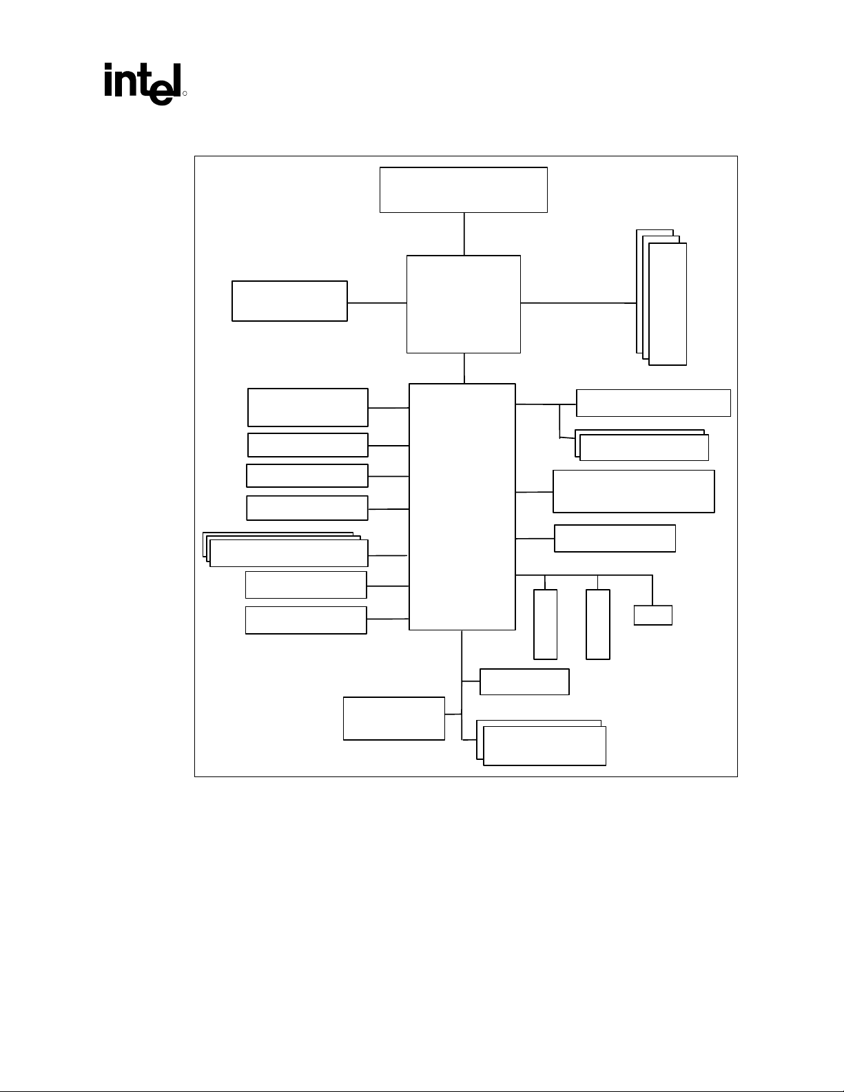
Figure 1. Block Diagram of Platform Chipset with Intel
ICH5 Component
Process
M
e
GP
MCH
m
o
r
y
USB 2.0
(Supports 6 USB ports)
IDE-Primary
IDE-Secondary
SATA (2 ports)
C’97 Codec(s)
LAN Connect
GPIO
OtherASICs
(Optional)
Intel
ICH5
®
LPC I/F
Super I/O
Firmware
Hub(s)
PCI Bus
S
L
O
T
Power Management
Clock Generators
System Management
(TCO)
SMBus 2.0/I 2 C
S
L
...
O
T
LAN
AC ’97 Programmer’s Reference Manual 13
Page 14
Overview
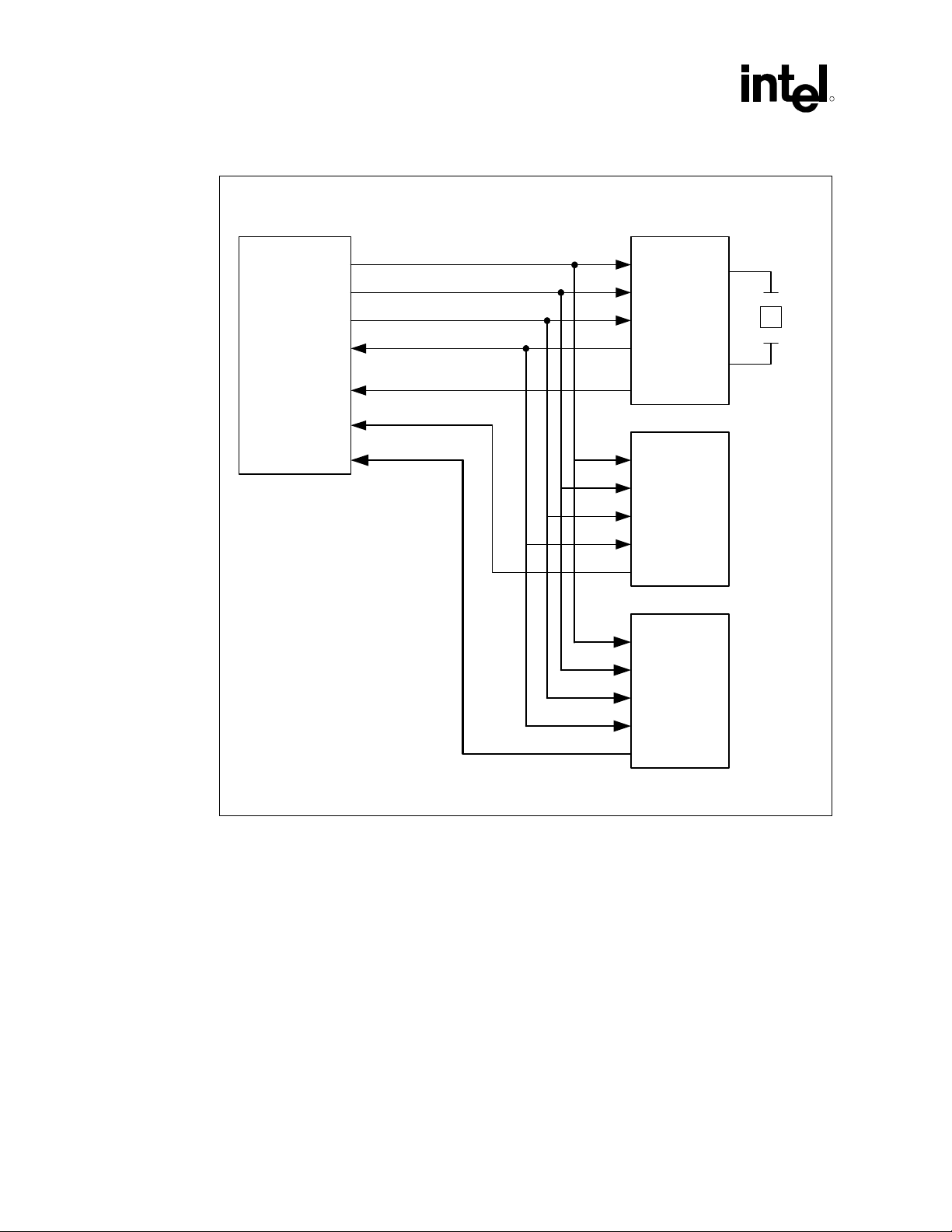
Figure 2. Intel
®
ICH5 AC ’97 Controller Connection to Its Companion Codecs
Digital Controller
RESET#
SDATA_OUT
SYNC
BIT_CLK
Intel® ICH
SDATA_IN_0
SDATA_IN_1
SDATA_IN_2
AC '97/AC '97 2.x/AMC '97
Primary Codec
AC '97/MC '97 2.x/AMC '97
Secondary
Codec
R
AC '97/AC '97 2.x/AMC '97
Tertiary Codec
2.1.1 Third AC ’97 Component Specification Revision 2.1, Revision 2.2 and Revision 2.3 Compliant Codecs
The AC ’97 Component Specification provides capability for up to four, SDATA_IN signals in
support of up to four codecs. The ICH5 AC ’97 controller provides support for up to three codecs
to allow for Audio channel expansion without sacrificing the Modem Codec (MC) support. Also,
the third codec capability enables a better mobile docking infrastructure.
2751_2
14 AC ’97 Programmer’s Reference Manual
Page 15

Overview
R
2.1.2 Dedicated S/P DIF DMA Output Channel
The ICH5 controller provides a dedicated DMA engine with the capability of outputting either
PCM or AC-3 data to the S/P DIF link for pass-through to an external CE audio decoder. This
capability allows for simultaneous output of PCM/AC-3 on the S/P DIF link while PCM data is
output to the PCM Out DMA engine. As a result, an AC3 stream from DVD movie playback can
be output on the S/P DIF link concurrently with other system audio data (e.g., voice audio from a
telephony application).
2.1.3 20 Bits Surround PCM Output
The AC ’97 Component Specification provides a maximum bit resolution of 20 bits per sample.
The ICH5 AC ’97 controller PCM Output DMA Engine fully exploits this capability to improve
the audio output quality.
2.1.4 Memory Map Status and Control Registers
The ICH5 support PCI Memory Base Address Register that allows for higher performance access
to the controller registers while expanding the register space to access the third codec support
mechanism. All features can now be accessed via this Memory BAR making the I/O BAR
capabilities obsolete. However, the ICH5 controller may maintain the I/O BAR capability to allow
for the reuse of legacy code maintaining backward compatibility to deployed driver binaries.
Note: This document describes the programming interface using the Memory BAR registers unless
otherwise indicated. The default configuration for ICH5 Audio function is to use the PCI Memory
Base Address Register. The I/O BAR is therefore disabled unless system BIOS enables the
simultaneous backward-compatible capability on the register:
Device 31 Function 5 Audio
Offset Register Default Comments
41h CFG
Configuration
00h When cleared, the I/O space BARs at offset 10h and 14h become
read only registers. This is the default state for the I/O BARs.
Initialized by BIOS when backward I/O Bar compatibility is
required Memory BARs are always enabled.
AC ’97 Programmer’s Reference Manual 15
Page 16

Overview
2.1.5 Second Independent Input DMA Engines
The ICH5 continues to provide two sets of input DMA engines that allow for the secondary or
tertiary codecs to provide recording PCM data streams on the primary codec while simultaneously
providing recording capabilities from the secondary or tertiary codec. A typical application is to
provide independent input stream in a mobile docking configuration where an audio codec is
located in the base system (notebook unit) and the secondary or tertiary codec is located in a
docking unit for desktop replacement. The DMA engines provide the infrastructure for s/w to
select the input stream from either source for stereo or microphone recording. Also the capability
of simultaneous input streams opens the possibilities for more futuristic applications where a
multiple microphone array can be created using two codecs. Refer to Section 3.2 for more
information on how to program the DMA engines.
2.1.6 PCI Local Bus Specification, Revision 2.3 Power Management
The ICH5 provides PCI Local Bus Specification, Revision 2.3-compliant power management
registers that allows for better OS power management support with reduced overhead to the BIOS
programmers using ACPI control methodologies.
R
2.2 General Requirements
It is assumed that the reader has a working knowledge of AC ’97 architecture and the ICH5 AC’97
controller implementation. Also, the reader should have an understanding of audio driver
development for the target operating systems.
This document outlines the software specification for the AC ’97 digital controller, and also
includes details necessary for development of an audio device driver.
16 AC ’97 Programmer’s Reference Manual
Page 17

Intel® ICH5 AC ’97 Controller Theory of Operation
R
3 Intel® ICH5 AC ’97 Controller
Theory of Operation
The ICH5 AC ’97 digital controller (DC) interface is an implementation of the AC-link, with
additional features to support the transaction and device power management. The ICH5 AC’97 DC
includes DMA engines for high-performance data transfer to memory via a hub interface.
ICH5 AC’97 DC and AC-link support isochronous traffic, which emphasizes the timing of the
data. This is critical to maintain the data stream from the audio and/or modem codec.
3.1 Intel® ICH5 AC ’97 Initialization
3.1.1 System Reset
The ICH5 AC ’97 circuitry is reset on power up by combining the PCIRST# signal with the AC
Link RESET# signal. However, AC Link RESET# will not follow PCIRST# during a resume from
sleep condition. During operation, the system can be reset by clearing the AC ’97 cold reset bit in
the Global Control/Status register (GLOB_CNT). This bit is maintained during ICH5 sleep mode
and can be used by the driver to select warm or cold reset during a resume condition. At least one
codec must be present. Otherwise, ICH5 AC ’97 is not supported and the codec ready will never
be seen by the controller. Once the reset has occurred, a read to Mixer register 00h/80h will
indicate what type of hardware resides in the codec(s).
Software must ensure that the codec ready bit is present for the appropriate Global Control/Status
register (GLOB_CNT). Before writing any value on the codec registers or initiating a DMA
transfer, s/w must ensure that the codec has reached a ready status by reading the Audio codec
register Powerdown Control/Status register (Index 26h) or Extended Modem Status and Control
register (Index 3Eh) correspondingly.
3.1.2 Codec Topology
The following rules present the allowable codec configuration when attaching to the AC-link
interface. To avoid improper driver loading, the system BIOS should determine the presence of the
audio or modem codec attached on the AC-link, and enable the Audio or Modem function’s PCI
configuration space accordingly.
The following are the loading rules for ICH5:
1. Maximum of three codecs total on the link
2. Maximum of a single modem function, either as Modem Codec or a combination
Audio/Modem Codec
This information is used to disable (hide) the appropriate PCI function. To determine that a codec
or codecs are attached to the link, the System BIOS follows an algorithmic approach.
AC ’97 Programmer’s Reference Manual 17
Page 18

Intel® ICH5 AC ’97 Controller Theory of Operation
Drivers can distribute output and input data in appropriate slots associated with available codec(s).
For example a 6-channel data stream can be separated into three, 2-channel codec streams as long
as the codecs are programmed to decode the appropriate slot output stream (SDATA_OUT).
Similarly ICH5 provides two stereo PCM input channels as well as two microphone mono input
DMA channels. These allow for separate input streams for stereo PCM and microphone recording
from two different codecs simultaneously.
Software should match sample rates, when two codecs are teamed together. The codecs must have
matching vendors, types, and be explicitly supported in software. Essentially, audio codecs must
be programmed with a common sample rate. The selection of a common sample rate is based on
each codec’s capabilities, as detailed in Section 3.5.3.
3.1.3 BIOS PCI Configuration
The ICH5 AC ’97 controller, as previously indicated, exposes two PCI functions in the ICH5 (Bus
0, Device 31h). This allows for driver differentiation between these capabilities in the component.
• Function 5: ICH5 AC ’97 audio controller
• Function 6: ICH5 AC ’97 modem controller
As PCI devices there are a number of registers that are required to be initialized to enable these
functions. The following table summarizes these requirements.
R
Table 3. Audio Registers
Device 31 Function 5 Audio
Offset Register Default Comments
04h-05h Command (COM) 0000h
10h-13h Native Audio Mixer Base
Address (NAMBAR)
14h - 17h Native Audio Bus
Mastering Base Address
(NABMBAR)
18h – 1Bh Memory Audio Mixer
Base Address (MMBAR)
1Ch – 1Fh Memory Bus Master
Base Address Register
(MBBAR)
3Ch Interrupt Line (INTLN) 00h A hardware interrupt (0-Fh) that follows value assigned to PIRQB#.
41h CFG Configuration 00h When cleared, the I/O space BARs at offset 10h and 14h become
00000001h When enable in 41h Address in the 64- K I/O space that allows
00000001h When enable in 41h Address in the 64-K I/O space that allows
00000000h Address in the 4-GB memory space that allows 512 bytes of
00000000h Address in the 4-GB memory space that allows 512 bytes of
Bit 2: Bus Master Enable
Bit 1: Memory Space Enable
Bit 0: When enable in 41h I/O Space Enable
256 bytes of registers not in conflict with any other set
256 bytes of registers not in conflict with any other set
registers not in conflict with any other set
registers not in conflict with any other set
Has not effect on ICH5 it is used to indicate software the IRQ value
assigned to the device.
read only registers. This is the default state for the I/O BARs.
Initialize by BIOS when backward I/O Bar compatibility is required
Memory BARs are always enabled.
18 AC ’97 Programmer’s Reference Manual
Page 19

Intel® ICH5 AC ’97 Controller Theory of Operation
R
Table 4. Modem Registers
Device 31 Function 6 Modem
Offset Register Default Comments
04h-05h Command (COM) 0000h Bit 2: Bus Master Enable
10h-13h Native Audio Mixer Base
Address
14h - 17h Native Audio Bus
Mastering Base Address
(MBAR)
3Ch Interrupt Line (INTLN) 00h A hardware interrupt (0-Fh) that follows value assigned to PIRQB#.
00000001h Address in the 64-K I/O space that allows 256 bytes of registers not
00000001h Address in the 64-K I/O space that allows 256 bytes of registers not
Bit 0: I/O Space Enable
in conflict with any other set
in conflict with any other set
Has not effect on ICH5 it is used to indicate software the IRQ value
assigned to the device.
With the exception of register 41h on Device 31 Function 5, initialization of the PCI registers
above is the responsibility of the PnP capable OS. If a PnP OS is not available in the system, it is
then the BIOS’s responsibility to configure all PCI devices including the registers above.
Determination of the presence of PnP capable OS is usually made via a switch in the System
Setup. However, the final configuration or the existence or not of this switch is implementation
dependent.
The ICH5 AC’97 controllers also provide PCI Power Management functionality. PCI Power
Management Registers are available via the configuration space. Handling of the Power
Management registers is responsibility of the OS PCI Bus driver following standard procedures.
For further discussion on the usage model for this registers, refer to Section 3.6, Power
Management.
3.1.4 Hardware Interrupt Routing
The audio and modem functions in the ICH5 internally share the same PCI IRQ (PIRQB#). The
configuration software must take this into account and assign the same IRQ pin to both functions.
Sharing IRQs increases the ISR latencies. Each ISR must determine if the interrupting device is the
one serviced by the routine, as determined by the OS programming model. PIRQB# it is also
exposed as a PCI IRQ.
In an environment where a high Quality of Service (QoS) is required, system designers must pay
close attention to devices attached to the same PIRQ. Software driven signal processing functions,
as in the case of software driven modem and audio, require maintaining a low latency interrupt
service in order to maintain proper functionality. Software driver programmers need to pay close
attention to the ISR latencies and make use of Deferred Procedure Calls (DPC) as much as
possible.
3.1.5 PCI Lock
Note that host controllers are not required to support exclusive-access mechanisms (such as PCI
LOCK) for accesses to the memory-mapped register space. Therefore, if software attempts
exclusive-access mechanisms to the AC ’97 host controller memory-mapped register space, the
results are undefined.
AC ’97 Programmer’s Reference Manual 19
Page 20

Intel® ICH5 AC ’97 Controller Theory of Operation
(
3.2 DMA Engines
The ICH5 AC ’97 controller uses a scatter gather mechanism to access memory. There are five,
16-bit DMA engines for Audio: 2 PCM Stereo In, 2 MIC mono in, and S/P DIF Out. There is one,
20-bit PCM 2/4/6 channel surround DMA engine. There are two, 16-bit DMA engines for Modem:
In and Out. Audio and Modem registers are located in two separate PCI functions in the ICH5
components to allow for driver development flexibility.
3.2.1 Buffer Descriptor List
The Buffer Descriptor List (BDL) allows device drivers to program DMA transfer using the ICH5
controller. The BDL is an array of up to 32 entries, each of which describes a data buffer. Each
entry contains a pointer to a data buffer, control bits and the length expressed as the number of
samples contained in the data buffer. The buffer length is restricted to 65535 samples. Samples can
be either 16 or 20 bits. Refer to section 3.4.1, for more details on the layout of samples in the data
buffer. A value of “0” in the buffer length indicates no samples to process. Each descriptor can
point to a buffer of a different size.
Figure 3. Generic Form of Buffer Descriptor (One Entry in the List)
R
(Dword 0 : - 03h)
31 1 0
Dword 1 : - 07h)
31 30 16 15 0
IOC BUP R Buffer Length
Table 5. BD Buffer Pointer (DWORD 0: 00-03h)
Bit Description
31:1 Buffer pointer. This field points to the location of the data buffer. Since the samples can be as
wide as 1 word, the buffer needs to be aligned to word boundaries to avoid having samples
straddle DWord boundaries.
0 Reserved. Must be 0 when writing this field.
Buffer Pointer 0
20 AC ’97 Programmer’s Reference Manual
Page 21
Intel® ICH5 AC ’97 Controller Theory of Operation
R
Table 6. BD Control and Length (DWORD 1: 04-07h)
Bit Description
31 Interrupt on Completion (IOC) 1= Enable , 0 = Disable. When this it is set, it means the
controller should issue an interrupt upon completion of this buffer. It should also set the IOC bit
in the status register.
30 Buffer Underrun Policy (BUP) 0 = When this buffer is complete, if the next buffer is not yet
ready, (last valid buffer has been processed) then continue to transmit the last valid sample.
1 = When this buffer is complete, if this is the last valid buffer, transmit zeros after this buffer is
completely processed. This bit will typically be set only if this is the last buffer in the current
stream.
29:16 Reserved. Must be 0 when writing this field.
15:0 Buffer length. This is the length of the data buffer in number of samples. The controller uses
this data to determine the length of the buffer in bytes. A value of 0 indicates no sample
process.
3.2.2 DMA Initialization
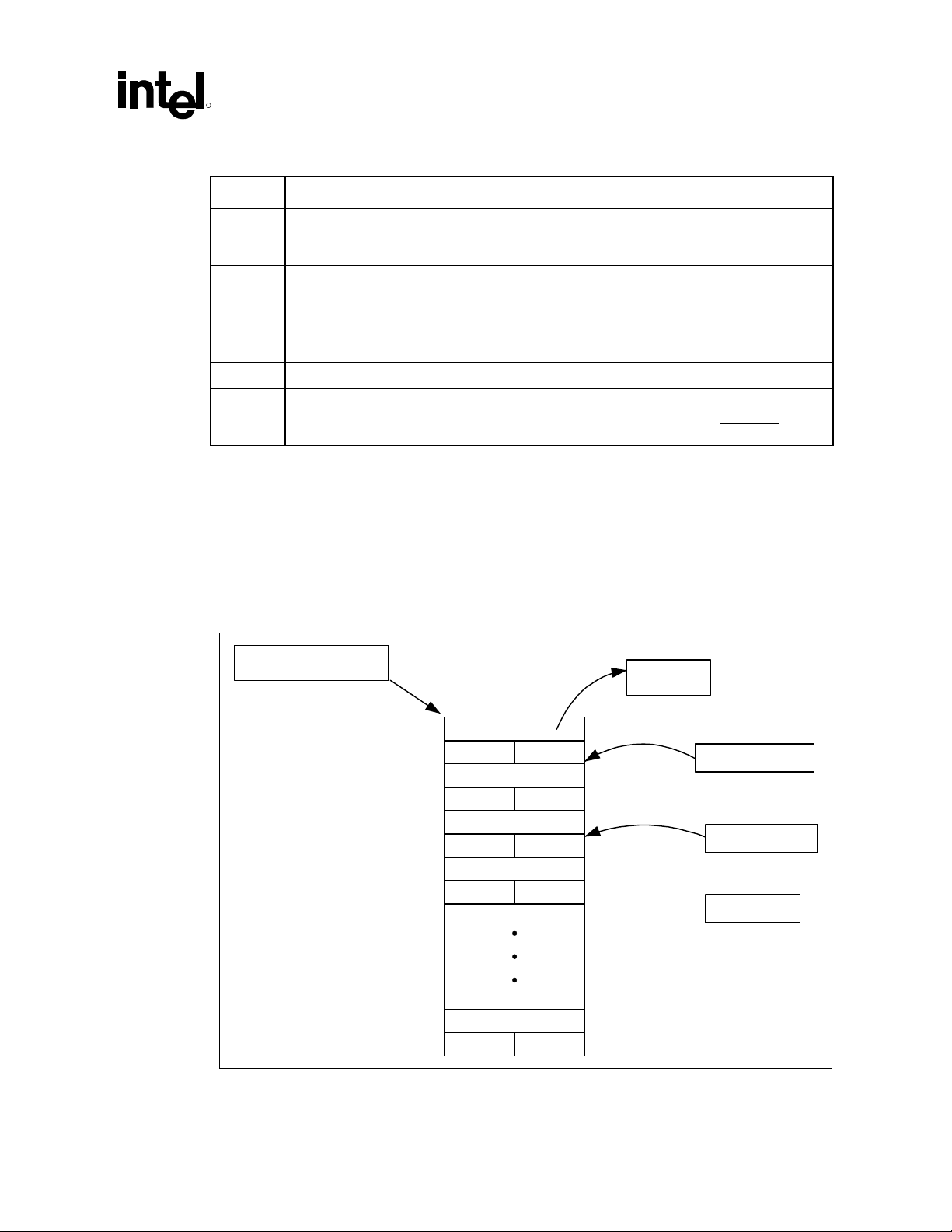
The maximum length of the buffer descriptor list is fixed at 32 (this is limited by the size of the
index registers). Figure 4, below, describes the organization of the Buffer Descriptor List.
Figure 4. Buffer Descriptor List
Buffer Descriptor List
Base Add
to
Data Buffer
Buffer Pointer
Command Length
Buffer Pointer
Command Length
Buffer Pointer
Command Length
Buffer Pointer
Command Length
Buffer Pointer
Command Length
n-1
n
n+1
Current Index
Pref etched Index
Last Valid
AC ’97 Programmer’s Reference Manual 21
Page 22

Intel® ICH5 AC ’97 Controller Theory of Operation
The following steps describe the driver initialization process for a single DMA engine. The same
process should be repeated for each DMA engine.
1. Create the buffer descriptor list structure in non-pageable memory.
2. Write the Buffer Descriptor List Base Address register with the base address of the buffer
descriptor list.
Table 7. Audio Descriptor List Base Address
Audio Buffer Descriptor List Base
Address
PCM IN MBBAR + 00h (PIBAR)
PCM OUT MBBAR + 10h (POBAR)
MIC MBBAR + 20h (MCBAR)
MIC 2 MBBAR + 40h (M2DBAR)
PCM2 IN MBBAR + 50h (PI2BAR)
SPDIF MBBAR + 60h (SPBAR)
Table 8. Modem Descriptor List Base Address
I/O Address:
R
Modem Buffer Descriptor List Base
Address
Line IN MBAR + 00h (MIBDBAR)
Line OUT MBAR + 10h (MOBDBAR),
3. Set up the buffer descriptors and their corresponding buffers. Buffers are usually passed to the
device driver as a list of descriptors that reference physical pages. These lists describe the
physical page numbers associated with the pages in the virtual audio buffer. Multiple buffer
descriptors may be required to represent a single virtual buffer passed to the device driver
4. Once buffer descriptors are set in memory, software writes the Last Valid Index (LVI)
register.
Table 9. Audio Last Valid Index
Audio Last Valid Index (LVI) I/O Address:
PCM IN MBBAR + 05h (PILVI),
PCM OUT MBBAR + 15h (POLVI),
MIC MBBAR + 25h (MCLVI)
MIC 2 MBBAR + 45h (M2LVI)
PCM2 IN MBBAR + 55h (PI2LVI)
SPDIF MBBAR + 65h (SPLVI)
I/O Address:
22 AC ’97 Programmer’s Reference Manual
Page 23

Intel® ICH5 AC ’97 Controller Theory of Operation
R
Table 10. Modem Last Valid Index
Modem Last Valid Index (LVI) I/O Address:
Line IN MBAR + 05h (MILVI)
Line OUT MBAR + 15h (MOLVI),
5. After LVI registers are updated, software sets the run bit in the control register to execute the
descriptor list.
3.2.3 DMA Steady State Operation
Software has two concurrent activities to perform while in normal operation: Preparing new
buffers/buffer descriptors and marking processed buffer descriptors and buffers as free. Once the
run bit is set in the bus master control register bit 0, the bus master fetches the buffer descriptor.
1. Bus master starts processing the current buffer. Once current buffer is processed, depending
upon the bits set in the command field, the interrupt is asserted and the interrupt bit is set.
2. Bus master increments the current and pre-fetch indices. It then starts executing the current
buffer and schedules the next buffer to be pre-fetched.
3. Buffer service routine maintains a variable that points to the head of the list of descriptors to
be processed. The descriptor list service routine performs the following activities:
// Update head of descriptors to be processed
While (head != current_index)
{
Mark head free ;
// check for end of descriptor list
If head == base_address + (31 * 8);
// last entry on the list, set head to top of the list
head = base_address;
Else
// still inside the list, increment head to next entry
head++;
Caution: This algorithm needs to be optimized to reduce the number of memory accesses during
execution. The “while” statement could translate to several memory access if this code is not
execute after each buffer descriptor update.
Also, the routine that prepares buffers maintains a variable that points to the entry after the tail of
the list. This value is always the next entry after the Last Valid Index register. It follows the
following algorithm:
// Update tail of descriptor list ready for execution and audio
// buffers when available for processing
While ((tail == free) && (buffers_available > 0))
{
Prepare buffer descriptor indexed by tail;
buffers_available--;
//assign tail to Last Valid Index
LVI = Tail;
// check for end of descriptor list
If (tail == base_address + 31 * 8);
// last entry on the list, set tail to top of the list
tail = base_address;
Else
AC ’97 Programmer’s Reference Manual 23
Page 24

Intel® ICH5 AC ’97 Controller Theory of Operation
// Advance tail to next value
tail++;
}
3.2.4 Stopping Transfers
There are two ways that DMA transfers can be stopped.
1. By simply turning off the Bus Master run/pause bit. This will halt the current DMA transfer
immediately. Data in the output FIFOs will continue to be read out until they empty. The
registers will retain their current values and AC-link corresponding slots will be invalidated.
Setting the run/pause bit will resume DMA activity.
2. Software can stop creating new buffers and hence not update the last valid index register. The
bus master will stop once the last valid buffer has been processed. All register information is
maintained. During this condition the controller will transmit the last valid sample or zeros
pending the status of the Buffer Underrun Policy (BUP) bit in the buffer descriptor entry. If
the run/pause bit remains set, then any future update to the Last Valid Index register will cause
the bus master operation to resume.
Note: Software must ensure that the DMA controller halted bit is set before attempting to reset
registers.
R
3.2.5 FIFO Error Conditions
Two general conditions could result in the FIFO error bit 4 in the status register being set. Pending
the status of bit 3 in the control register it will also cause an interrupt.
3.2.5.1 FIFO Underrun
FIFO underrun will occur when the ICH5 AC ’97 controller FIFO is drained:
1. As a result of system congestion. The DMA read transaction could still be pending as data has
not returned from memory. In this case the controller will repeat last sample until new data is
available in the FIFO.
2. As a result of DMA engine reaching the Last Valid Index, no further access to memory,
therefore FIFO will drain. In this case the controller will transmit the last valid sample or
zeros pending the status of the Buffer Underrun Policy (BUP) bit in the buffer descriptor
entry. This condition is an error if software is not able to update the descriptor list before the
DMA engine reaches the Last Valid Index. However, this condition could be as result of the
completing processing the last buffer. It is up to the software driver to determine the final
status of this condition. See also Stopping Transfers, Section 3.2.4.
3.2.5.2 FIFO Overrun
FIFO overrun will occur when valid data is transmitted in proper AC-link slots and DMA FIFO
remains full. Two conditions could result in the FIFO error bit 4 in the status register being set.
Pending the status of bit 3 in the control register it will also cause an interrupt.
1. As a result of DMA engine not being able to update system memory with the content of the
FIFO. This is a result of system congestion. In this case, all new samples received from the
AC-link will be lost.
24 AC ’97 Programmer’s Reference Manual
Page 25

Intel® ICH5 AC ’97 Controller Theory of Operation
R
2. As a result of the DMA engine reaching the Last Valid Index, no further access to memory,
therefore FIFO will not drain. This condition is an error if software is not able to update the
descriptor list before the DMA engine reaches the Last Valid Index. However, this condition
could be the natural result of the last buffer entry been processed. It is up to the software
driver to determine the final status of this condition. See also Stopping Transfers in paragraph
above.
3.3 Channel Arbitration
It is possible for up to eight ICH5 AC ’97 DMA channels to be enabled at one time. A round-robin
arbitration scheme is used to arbitrate between these channels.
3.4 Data Buffers
3.4.1 Memory Organization of Data
Samples are packed in an interleaved format: two samples for two channel (stereo), four samples
for four channels surround and six samples for six channels surround.
The actual PCM data is "left-aligned" within the container. The sample itself is justified most
significant; all extra bits are at the least-significant portion of the container. All non-valid data bits
must be set to 0. With 20 bit data, the "top" 20 bits (31-12) of the DWORD contain the data. The
bottom 12 bits (11-0) are not valid data. The sample data must be WORD aligned.
3.4.2 PCM Buffer Restrictions
Below are the memory buffer restrictions for ICH5 PCM that applies for 2-, 4-, and 6-channel
audio mode:
1. Buffer Descriptors Must Contain Integer Multiples of Framed Samples and Are Frame
Aligned:
Example: Two channel buffers must contain an integer multiple of two samples.
Four channel buffers must contain a multiple of four samples and six channel
buffers must contain a multiple of six samples. The controller does not support a
frame (e.g., left and right samples for two channel) spanning multiple
descriptors. Similarly, the controller does not support a buffer descriptor with a
single sample (PCM out MONO is not supported). Also, odd length buffers are
not allowed due to the sample alignment requirements.
2. Software Is Allowed to Create an Empty Frame (0 Samples) in a Buffer Descriptor with the
Following Restriction:
An empty buffer has to be part of a list of buffer descriptors and it cannot to be
the first Buffer Descriptor or the last Buffer Descriptor of the list. A series of
buffer descriptors with 0 samples are possible in the lists as long as they are not
the first or the last. The last Buffer Descriptor in the list is determined by the last
valid index (LVI) that is programmed.
AC ’97 Programmer’s Reference Manual 25
Page 26
Intel® ICH5 AC ’97 Controller Theory of Operation
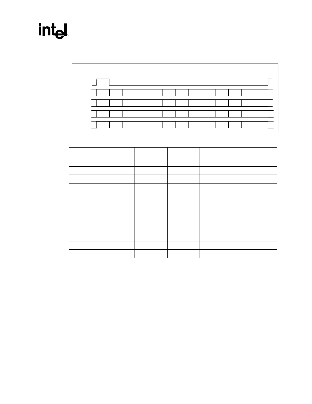
3.4.3 FIFO Organization
The ICH5 AC ’97 controller supports 16-bit samples on all channels except PCM Out, which also
supports 20-bit samples.
Data will be written to the FIFO in sample pairs following the order of valid slots in a channel. For
example, for audio PCM In, the controller will check the first valid slot and add it to the FIFO first
entry as a word (16 bits). The next valid slot will be added as the second word entry in the FIFO to
create the PCM stereo sample pair. This behavior works under the assumption that the first valid
slot will be always the Left channel (slot 3) followed by Right channel in slot 4 in the same or
subsequent frame. If the codec transmits data repeating the slot, it will cause the controller to
misplace the sample in the FIFO. Codecs compatible with the ICH5 AC ’97 implementation
should always maintain the indicated order, and never use the same slot twice to transmit samples
to the controller. The figures below present some ICH5 compatible and incompatible
implementations using as a reference a two-channel implementation.
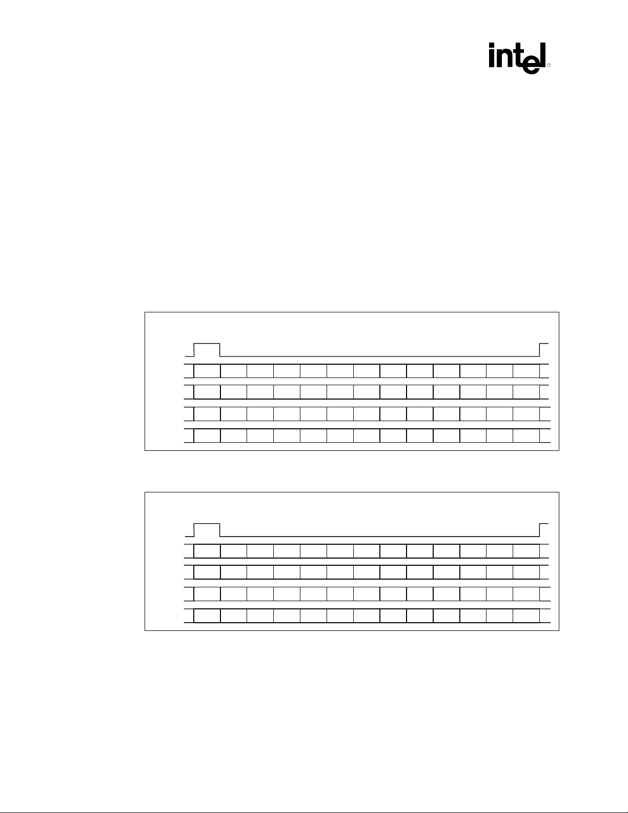
Figure 5. Compatible Implementation with Left and Right Sample Pair in Slot 3/4 Every Frame
Slot #
SYNC
CMD
DATA
4
5 6 7 8 9 10 11 12210 3
R
Frame n
Frame n + 1
Frame n + 2
Frame n + 3
TAG X
TAG X
TAG X
TAG X
ADR
Status
ADR
CMD
ADR
Status
ADR
DATA
CMD
Status
DATA
Data
CMD
CMD
DATA
Data
CMD
Status
DATA
Data
CMD
CMD
MDM
X
X
X
X
RSVD RSVD RSVD RSVD RSVD RSVD
CDC
MDM
MIC RSVD RSVD RSVD RSVD RSVD
CDC
MDM
RSVD RSVD RSVD RSVD RSVD RSVD
CDC
MDM
MIC RSVD RSVD RSVD RSVD RSVD
CDC
I/O
Control
I/O
Status
I/O
Control
I/O
Status
Figure 6. Compatible Implementation with Sample Rate Conversion Slots 3 and 4 Alternating
over Next Frame
Slot #
SYNC
Frame n
Frame n + 1
Frame n + 2
Frame n + 3
CMD
DATA
CMD
CMD
TAG X
TAG
TAG X
TAG
ADR
Status
ADR
CMD
ADR
Status
ADR
DATA
CMD
Status
DATA
Data
CMD
CMD
DATA
Data
CMD
Status
DATA
Data
4
5 6 7 8 9 10 11 12210 3
MDM
RSVD RSVD RSVD RSVD RSVD RSVD
CDC
MDM
X
X
MIC RSVD RSVD RSVD RSVD RSVD
CDC
MDM
RSVD RSVD RSVD RSVD RSVD RSVD
CDC
MDM
MIC RSVD RSVD RSVD RSVD RSVD
CDC
I/O
Control
I/O
Status
I/O
Control
I/O
Status
26 AC ’97 Programmer’s Reference Manual
Page 27
Intel® ICH5 AC ’97 Controller Theory of Operation
R
Figure 7. Incompatible Implementation of Sample Rate Conversion with Repeating Slots over
Next Frames
Slot #
SYNC
Frame n
Frame n + 1
Frame n + 2
Frame n + 3
TAG X
TAG
TAG
TAG X
Table 11. FIFO Summary
Channel # of Samples FIFO Depth FIFO Width Comments
Mic In 1 2 32 bits 2 frame 1 dword
Mic2 In 1 2 32 bits 2 frame 1 dword
PCM In 2 4 32 bits 1 frames per dword
PCM2 In 2 4 32 bits 1 frames per dword
PCM Out 6, 4 or 2 24 32 bits 1 frames per dword (2 –16 bits ch),
Modem In 1 2 32 bits 2 frames per dword
Modem Out 1 2 32 bits 2 frames per dword
CMD
ADR
Status
ADR
CMD
ADR
Status
ADR
CMD
DATA
CMD
DATA
CMD
Status
DATA
Data
CMD
CMD
DATA
Data
CMD
Status
DATA
Data
4
5 6 7 8 9 10 11 12210 3
MDM
RSVD RSVD RSVD RSVD RSVD RSVD
CDC
MDM
X
X
MIC RSVD RSVD RSVD RSVD RSVD
CDC
MDM
RSVD RSVD RSVD RSVD RSVD RSVD
CDC
MDM
MIC RSVD RSVD RSVD RSVD RSVD
CDC
I/O
Control
I/O
Status
I/O
Control
I/O
Status
1 frame per 2 dword (2 –20 bits ch)
1 frame per 2 dword (4 –16 bits ch)
1 frames per 4 dword (4 –20 bits ch)
1 frames per 3 dword (6 – 16 bits ch.)
1 frames per 6 dword (2 –20 bits ch)
NOTES:
1. One audio frame worth of data for the specific DMA channel.
3.5 Multiple Codec/Driver Support
The ICH5 AC ’97 controller is capable of supporting a three-codec implementation. Under this
implementation all codecs share the SDATA_OUT signal while independent SDATA_IN[0:2] are
used by the codec to supply data to the controller. ICH5 allows for a compatible behavior, where
the three SDATA_IN are used, these signals are logically OR’d inside the digital controller,
effectively creating one digital input data stream. However, ICH5 also allows for an independent
SDATA_IN functionality. In this case, the SDATA_IN Map Register (SDM) MBBAR + 80h is
used to steer the content of the input slots to the appropriate controller DMA engine. This
capability also allows for a more reliable enumeration algorithm of the available codecs.
AC ’97 Programmer’s Reference Manual 27
Page 28

Intel® ICH5 AC ’97 Controller Theory of Operation
Table 12. SDM Register Description
Bit Type Reset Description
PCM In 2, Microphone In 2 Data In Line (D21L): When the SE bit is set, these bits
indicate which SDATA_IN line should be used by the hardware for decoding the
input slots for PCM In 2 and Microphone In 2. When the SE bit is cleared, the value
of these bits is irrelevant, and PCM In 2 and Mic In 2 DMA engines are not
available.
7:6 RW 00
5:4 RW 00
3 RW 0
2 RO 0 Reserved
1:0 RO 00
00 SDATA_IN0
01 SDATA_IN1
10 SDATA_IN2
11 Reserved
PCM In 1, Microphone In 1 Data In Line (DI1L): W hen the SE bit is set, these bits
indicates which SDATA_IN line should be used by the hardware for decoding the
input slots for PCM In 1 and Microphone In 1. When the SE bit is cleared, the value
of these bits are irrelevant, and the PCM In 1 and Mic In 1 engines use the OR’d
SDATA_IN lines.
00 SDATA_IN0
01 SDATA_IN1
10 SDATA_IN2
11 Reserved
Steer Enable (SE): When set, the SDATA_IN lines are treated separately and not
OR’d together before being sent to the DMA engines. When cleared, the
SDATA_IN lines are OR’d together, and the “Microphone In 2” and “PCM In 2”
DMA engines are not available.
Last Codec Read Data Input (LDI): When a codec register is read, this indicates
which SDATA_IN the read data returned on. Software can use this to determine
how the codecs are mapped. The values are:
00 SDATA_IN0
01 SDATA_IN1
10 SDATA_IN2
11 Reserved
R
3.5.1 Codec Register Shadowing
Codec register reads are presented in the AC-link in the next available frame after the controller
receives the I/O transaction. Data will be returned to the controller pending codec availability. To
avoid longer latencies than necessary, the codec must return data in the next available frame.
Multiple frame transactions impose large system latencies, to the detriment of system performance.
Even when data is returned in the frame immediately after the read request is presented in the AClink, the minimum latency is still on the order of 40 µs. To minimize the effect on the system
caused by long latencies in the AC-link, software drivers must maintain a copy of the codec
register in memory (shadow) and use this data instead of accessing the codec.
28 AC ’97 Programmer’s Reference Manual
Page 29

Intel® ICH5 AC ’97 Controller Theory of Operation
R
Shadowing in memory is effective as long as the codec itself does not change the value of the
registers. Therefore, the status of the GPIOs configured as inputs on the most recent frame is
accessible to software by reading the register at offset 54h in the modem codec I/O space. Only the
16 MSBs are used to return GPI status. Reads from 54h will not be transmitted across the link.
Instead, data received in slot 12 is stored internally in the controller, and the data from the most
recent slot 12 is returned on reads from offset 54h.
The Powerdown in codec offset 26h and 3Eh status registers are not supported by an automatic
shadowing mechanism, as is the case for offset 54h. However, these registers are sparingly used.
These registers are read only during power down status determination.
Finally, codec ready status is required during system initialization. It is automatically reflected in
the Global Status Register at MBBAR + 30h (MBAR + 40h) bit 8 for the SDATA_IN0 codec, bit
9 for the SDATA_IN1 codec and bit 28 for theSDATA_IN2 codec. These three bits need not be
saved in memory.
3.5.2 Codec Access Synchronization
All codec register writes are posted transactions in the ICH5 AC ’97 controller. The ICH5 AC ’97
controller will indicate transaction completion to the host processor immediately following the
request even when the transaction is actually pending for completion in the AC-link. This is done
to improve system performance. However, it also imposes restrictions in the driver(s) operation.
Also, register reads present synchronization issues.
Before a codec register access is initiated, the driver must check the status of the Codec access in
Progress (CAIP) bit 0 in the Codec Access Register at MBBAR + 34h (MBAR + 44h.) If no write
is in progress, this bit will be ‘0’ and the act of reading the register sets this bit to ‘1’. This reserves
the driver the right to perform the I/O read or write access. Once the write is complete, hardware
automatically clears the bit. The driver must also clear this bit if it decides not to perform a codec
I/O write after having read this bit. If the bit is already set, it indicates that another driver is
performing a codec I/O writes across the link and the driver should try again later.
3.5.3 Data Request Synchronization in Audio Split Configurations
To support more than 2 channels of audio output, the AC ’97 Component Specification, Revision
2.1 allows for a configuration where up to three audio codecs work concurrently to provide
surround capabilities (refer to AC ’97 Component Specification, Revision 2.3) To maintain data on
demand capabilities the Intel controller, when configured for 4 or 6 audio channels, will wait for
all the appropriate Slot Request bits to be set before sending data in the SDATA_OUT slots. This
allows for a simple FIFO synchronization of the attached codecs.
If the codecs on the link are not compatible, or are not known to be compatible, with respect to
sample rate conversion algorithms and FIFO depth requirements (for instance, all codecs being the
same revision of the same model from the same vendor), Variable Rate support should not be
used, and a fixed sample rate of 48 MHz is recommended to maintain synchronization across the
codecs in use.
AC ’97 Programmer’s Reference Manual 29
Page 30

Intel® ICH5 AC ’97 Controller Theory of Operation
3.6 Power Management
Power management of the driver/codec interaction requires careful sequencing in the ICH5 AC ’97
environment. In the ICH5 AC ’97 environment it is possible to have two drivers sharing the same
AC-link interface for two separate codecs or a single driver controlling two separate audio codecs.
A driver forcing an aggressive sleep state in the link could have functional repercussions on the
pairing codec. The Deep Sleep state in a device following ACPI compliance requirements is the
D3 State. When a driver is requested to set its device to the D3 State, the driver should enter the
most aggressive power saving mode possible. The D3 State is also often the precursor to a system
wide core power removal. Therefore several considerations must be taken into account to maintain
the device functionality and wake-up capability.
3.6.1 Codec Topologies
The procedure to be taken by an ICH5 AC ’97 device driver varies depending on the system
configuration. The following table enumerates the possible codec combinations supported by the
ICH5 AC ’97 controller.
The ICH5 audio/modem controller supports a maximum of three codecs. If there is more than one
audio codec, then the remaining codecs must proceed to the different power states at the same
time. The following system implementations are possible.
R
Table 13. Dual Codecs Topologies
Config.
1 AC (Primary)
2 MC (Primary)
3 AMC (Primary) Possible D3 state interactions
4 AC (Primary) + MC (Secondary) Possible D3 State interactions
5 AC (Primary) + AC (Secondary) Driver interaction concern
6 AMC (Primary) + AC (Secondary) Possible D3 State Interactions
7 AC (Primary) + AMC (Secondary) Possible D3 State Interactions
Note: The configuration above could be further limited by ICH5 AC ’97 riser card configuration
and loading. Refer to the Audio/Modem I/O Riser Specification for details.
It is evident that Configurations 1 and 2, above, require no driver synchronization between ICH5
AC ’97 codecs. Configuration 1 and 2 are single codec topologies, and therefore an aggressive
power saving mode is possible including disabling of the actual AC-link without concern of
affecting paired codec functionality.
Configuration 3 is a single codec topology that provides both functions audio and modem. In this
configuration driver interaction is also critical if a separate set of drivers are in control of the audio
and modem functions.
Configuration 4, however, is a two-codec topology. In this configuration an aggressive power
saving mode requires detailed attention to cross interactions and the effect on AC-link
functionality.
30 AC ’97 Programmer’s Reference Manual
Page 31

Intel® ICH5 AC ’97 Controller Theory of Operation
R
Configuration 5 is a two-codec audio topology. In this configuration concerns are on the proper
power down sequence. However, no driver interaction is expected as only the audio driver
executes power management functions.
Configuration 6 is also a two-codec topology with split audio and integrated modem support. This
is the most complex interaction, as two different sets of driver will be operating in a complex
topology.
Configuration 7 is identical to configuration 6, with the primary and secondary codecs switched.
In order to power manage ICH5 AC ’97 codecs, there are two sets of PR bits that drivers need to
manage. One set is at offset MMBAR + 26h in the audio function, mapped to offset 26h in the
primary codec, and the second set is at MMBAR + 3Eh, mapped to offset 3Eh in the modem
function. Notice that register 3Eh does not provide link down functionality, this is provided in
register 56h bit 12, (MLNK) modem link.
3.6.1.1 Tertiary Codec Topologies
Table 12 lists configurations using a primary and secondary codec. ICH5 also supports
configurations involving a third (tertiary) codec. It is important to note that three codec
configurations are an extension of the corresponding two codec versions and have the same D3
interactions and issues. Therefore, the configurations, algorithms and pseudo-code described for
the secondary codec also apply and can be used for configurations that involve three codecs.
3.6.2 Power Management Transition Maps
The following paragraphs relate power management transition maps in the constraints of an ACPI
system environment. The tables below map codec PR bits transitions to specific ACPI “D” states
for the device.
The following considerations were made in the generation of the following tables:
• Power management is defined in the framework of a desktop system. Further power savings
are possible by implementing more aggressive power management typical of mobile
environment policies (see aggressive power management section below). However these
power savings are a trade off involving driver complexities and functional restrictions.
• Selection of a specific power policy below is pending the proper identification of the topology
by the driver(s).
• Secondary codec is provided with external clocking mechanism and is not dependent on
BIT_CLK to drive internal state machines when in power down mode.
• After warm or cold reset the device driver will bring all PR(x) bits to D0 state.
• Transition from/to any Dx state is accomplished by setting/resetting all appropriate PR(x) bit
simultaneously. Codec should not place limitations on the PR(x) bits transition sequence
represented above.
• Audio Codec Reg. 26h D15 EAPD (formerly PR<7> enable/disable function) is newly
defined as control for an external audio power amp. Audio codec should provide an audio
amp output pin (GPO) that provides off/on capability following this bit set/reset status.
• The modem tables assume Caller-ID capability during wake-up on ring, so Vref is on during
D3.
AC ’97 Programmer’s Reference Manual 31
Page 32

Intel® ICH5 AC ’97 Controller Theory of Operation
R
• Modem D3 configuration is dependent on wake-up on ring event enable. If wake-up on ring is
enabled, GPIO cannot go down in D3.
Note: When a codec section is powered back on the Powerdown Control/Status register (index 26h)
should be read to verify that the section is ready before attempting any further operations.
Configuration Number 1: Single Audio Codec (Primary):
Table 14. Power State Mapping for Audio Single or Dual (Split) Codec Desktop Transition
PR<0:5> + (EAPD)
E
Device
State
D0 0 0 0 0 0 0 0 On On On On All on
D1 0 0 0 0 0 1 1 On On On On -DAC, -ADC
D2 1 0 0 0 1 1 1 On On On On -Mix, -Amp
D3 1 1 1 1 1 1 1 Off Off Off On -Clock, -Vref
C
A
P
D
7 5 4 3 2 1 0
AC-
L
Link
K
Mixer
Vref.
Mixer D
A
C
+12 +5
A
D
C
from
+12
+3.3
Digital
+3.3
Vaux
Digital
Comments
Configuration Number 2: Single Modem Codec (Primary):
Table 15. Power State Mapping for Modem Single Codec Desktop Transition
PR<A:D> + MLNK
(other power control (PRx) bits do not apply for Intel
Sdata_In D
Device State MLNK D C B A
D0 0 0 0 0 0 On On On On All on
D1 0 1 1 0 0 On On On On -DAC, -ADC
D2 0 1 1 0 0 On On On On Same as D1
D3
(wake-up on ring)
D3 1 1 1 1 1 Off Off Off On -Sdata_In,
implementation)
A
A
D
C
C
1
1
1 1 1 0 0 Off Off Off On -Sdata_In,
®
ICH5
Vref GPIO
+12 +5
from
+12
+3.3
Digital
+3.3
Vaux
Digital
Comments
-Vref, -GPIO
32 AC ’97 Programmer’s Reference Manual
Page 33

Intel® ICH5 AC ’97 Controller Theory of Operation
R
Configuration Numbers 3 to 6: Dual Function Single or Dual Codec Configurations:
Table 16. Power State Mapping for Audio in Dual Codec Desktop Transition
PR<0:5> + (EAPD)
E
Device
State
D0 0 0 0 0 0 0 0 On On On On All on
D1 0 0 0 0 0 1 1 On On On On -DAC, -ADC
D2 1 0 0 0 1 1 1 On On On On -Mix, -Amp
D3 1 0 0 1 1 1 1 Off Off Off On -Clock, -Vref
C
A
P
D
7 5 4 3 2 1 0
NOTES:
AC-
L
Link
K
1. PR(4) link down and PR(5) internal clocks disable are NOT recommended for desktop configuration.
Setting these to power control bits could affect modem operation in an AC + MC configuration.
2. In a mobile system configuration, PR(4) and PR(5) could be used to provide further power savings.
Driver designers should use D3 state codec semaphores in the ICH5 AC ’97 controller to determine
audio or modem codecs power status before setting PR(4) and PR(5) bits. Please refer to ICH5 AC ’97
External Architecture Specification for details. The miniport driver developed for the ICH5 AC ’97
controller does not provide this capability.
3. In a dual audio codec transition, PR bits must be set in both of the codec registers. The primary audio
power management register set is always located MMBAR + 26h, the secondary audio codec power
management register set is located at MMBAR + A6h. Configuration software must sequence power
down to the secondary codec first and then the primary codec. The process is reversed at resume when
the primary codec is first restored and then the secondary.
Mixer
Vref.
Mixer D
A
C
+12 +5
A
D
C
from
+12
+3.3
Digital
+3.3
Vaux
Digital
Comments
AC ’97 Programmer’s Reference Manual 33
Page 34

Intel® ICH5 AC ’97 Controller Theory of Operation
R
Table 17. Power State Mapping for Modem in Dual Codec Desktop Transition
PR<A:D> + MLNK
(other power control (PRx) bits do not apply for Intel
Sdata_In D
Device State MLNK D C B A
D0 0 0 0 0 0 On On On On All on
D1 0 1 1 0 0 On On On On -DAC, -ADC
D2 0 1 1 0 0 On On On On Same as D1
D3
(wake-up on
ring)
D3 1 1 1 1 1 Off Off Off On -Sdata_In,
implementation)
A
A
C
1
1 1 1 0 0 Off Off Off On -Sdata_In,
Vref GPIO
D
C
1
®
ICH5
+12 +5
from
+12
+3.3
Digital
+3.3
Vaux
Digital
Comments
-Vref, -GPIO
Table 15 and Table 16 above, represent the recommended Power Transition Tables for a Desktop
System. The tables above preclude the need for a driver to provide codec topology detection
simplifying the initialization sequence. These tables do not provide the maximum power saving.
However, they are believed to provide sufficient power saving for the Desktop applications. The
OEM and IHV are free to provide further differentiation by allowing the deeper power savings
obtained by identifying the codec Topology.
3.6.3 Power Management Topology Considerations
A set of drivers could always assume Configuration Numbers 3 and 4, above, and establish their
power management policy based on Table 15 and Table 16. These are the safest configurations
with a semi-aggressive power management style consistent with a desktop environment. However,
even in a desktop environment, further power savings are possible when in Single Codec
Configurations Numbers 1 and 2. For the tables above to be implemented, the audio driver needs
to be able to determine the AC-link topology configuration.
3.6.3.1 Determining the Presence of Secondary and Tertiary Codecs
To determine that optional secondary and tertiary codecs are present, the driver needs to check
three Codec Ready bits located in the Global Status Register at:
Codec Ready: I/O Address: MBBAR + 30h (MBAR +40h) bits 8,9,28
If two of these three bits are set to 1, it indicates that a secondary codec is active in the AC-link.
If all three of these bits are set to 1, it indicates that a tertiary codec is active in the AC-link.
34 AC ’97 Programmer’s Reference Manual
Page 35

Intel® ICH5 AC ’97 Controller Theory of Operation
R
3.6.3.2 Determining the Presence of a Modem Function
In the case of an AMC configuration, only the primary codec ready bit will be indicated. In order
to determine proper power down configuration, the audio driver needs to determine the presence
of modem functionality in the codec. The audio driver could check the Extended Modem ID
register at:
Extended Modem ID: I/O Address: MMBAR + 3Ch
The content of this register will be FFh if no modem function is present.
3.6.4 Resume Context Recovery
When the system is placed in a powerdown state (S3 or greater) power is removed from the ICH5
AC ’97 controller. In this state DMA registers lose information regarding current position and
pointer values. The device driver must be able to save the context of all DMA engines before
acknowledging a D3 state. Device drivers must assume that D3 state request precedes a total
system powerdown causing context for the DMA engines to be lost. Upon system power resume,
the device driver must restore the DMA engine registers to the values saved prior to the suspend
event.
3.6.5 Aggressive Power Management
As indicated in previous sections it is possible to go into a more aggressive power savings mode
by carefully synchronizing audio and modem driver interactions over the AC-link. This aggressive
power savings is usually found in mobile environments where battery power is critical.
Driver synchronization is required in a dual codec configuration where the audio driver could
cause a link down power condition by setting the PR4 and PR5 bits in the audio codec register.
When PR4 and PR5 are set, the AC-link base clock BIT_CLK is stopped. If this action occurs
while the modem codec is still in operating mode, it will cause malfunctions and possibly a system
hang.
To avoid this and similar situations, the audio and modem driver could follow a protocol using the
provided audio and modem D3 state bit semaphores, AD3 for audio and MD3 for modem. These
bits are located at:
Codec Write Semaphore Registers:
NABMAR +30h Audio I/O Space and MBAR + 40h Modem I/O Space
bit 16 for Audio (AD3)
bit 17 for Modem (MD3)
ICH5 AC ’97 drivers should set the appropriate bit after setting the codec in a D3 state. The audio
codec could use this semaphore to determine if the modem codec is already in a D3 state and shut
down the link by also asserting PR4 and PR5 in the power management register in the audio
function/codec. The following sections review in detail the sequence of events for drivers/codec
entering a D3 state and a resume to D0.
AC ’97 Programmer’s Reference Manual 35
Page 36

Intel® ICH5 AC ’97 Controller Theory of Operation
3.6.5.1 Primary Audio Requested to D3
The audio power management procedure attempting to get the audio codec to D3 state.
If MD3 == true // (sleeping?)
{
Audio_Power_Manage_Reg = D3 + PR4 + PR5;
// yes, sleep plus AC Link down
}
Else
{
Audio_Power_Manage_Reg = D3; // No, sleep keeping link up
}
AD3 = true; // set to "audio sleeping"
// setting the flag last avoids race condition during
// D0->D3 transition.
3.6.5.2 Secondary Modem Requested to D3
The modem power management procedure will try to get the modem codec to D3 state.
Secondary_codec = D3 + MLNK // yes, sleep plus SDATA_IN1 low
MD3 = true
// setting the flag last avoids race condition during D0->D3
// transition.
// MLNK corresponds to register Reg. 56h bit 12 (D12)
R
3.6.5.3 Secondary Modem Requested to D0
The modem power management procedure will try to get the modem codec to D0 state.
MD3 = false // set to "modem awake"
// Setting the flag first avoid race condition during D3->D0
// transition
If Modem_ready == True
{
Modem_Power_Manage_Reg = D0 // Bring back to fully awake,
}
If AD3 == true // (audio sleeping?)
{
Link_reset() // cause a warm or cold reset
While (!Modem_ready) // wait for modem ready
{
read modem codec ready bit every 400 ms
}
Modem_Power_Manage_Reg = D0 // Bring back to awake,
}
36 AC ’97 Programmer’s Reference Manual
Page 37

Intel® ICH5 AC ’97 Controller Theory of Operation
R
3.6.5.4 Audio Primary Requested to D0
The audio power management procedure will attempt to get the audio codec to D0 state.
AD3 = false // set to "audio awake"
// Setting the flag first avoid race condition during D3->D0
// transition
If Audio_ready == True
{
Audio_Power_Manage_Reg = D0;
// Bring back to fully awake,
}
If MD3 == true; // (modem sleeping?)
{
Link_reset(); // cause a warm or cold reset
While (!Audio_ready); // wait for modem ready
{
read audio codec ready bit every 100ms;
}
Audio_Power_Manage_Reg = D0; // Bring back to awake,
}
3.6.5.5 Using a Cold or Warm Reset
In the pseudo code above there are several references to resetting the AC-link using
“Link_reset()”. Drivers need to differentiate if the system enters a suspend event where core power
is removed from the system before deciding to execute a Cold or Warm reset. A device is in a “D3
hot” state after the device is set in the lowest power consumption mode and core power is
maintained. A device is in a “D3 cold” state when the device is set in the lowest power
consumption mode and core power is removed.
In the ICH5 AC ’97 implementation when core power is removed the cold reset bit is reset “0”
This bit is located at:
MBBAR + 2Ch and MBAR + 3Ch
bit 1 ICH5 AC ’97 Cold Reset#.
A driver requested to resume to a D0 state from a D3 state must check the status of the ICH5 AC
’97 cold reset bit. If this bit has a value of “0” the driver will set it to “1” to de-assert the
AC_RESET# signal in the link, thus completing a cold reset. If the Cold Reset bit is set to “1” then
a warm rest is required if the AC-link is down by the procedures indicated under aggressive power
management. To execute an ICH5 AC ’97 warm reset the driver must set to “1” the ICH5 AC ’97
warm reset bit located at:
MBBAR + 2Ch and MBAR + 3Ch
bit 2 ICH5 AC ’97 Warm Reset#
AC ’97 Programmer’s Reference Manual 37
Page 38

Intel® ICH5 AC ’97 Controller Theory of Operation
A pseudo code representation is as follows:
void Link_reset(void)
{
If Cold_Reset# == True // AC_RESET# asserted, D3 when cold!
{
Cold_Reset# = False; // De-assert AC_RESET# Wake-up!
}
Else
{
Warm_reset = True; // D3 is Hot! Do warm reset
}
}
R
38 AC ’97 Programmer’s Reference Manual
Page 39

Surround Audio Support
R
4 Surround Audio Support
The AC ’97 Component Specification allows for up to six channels of audio supported in the AClink. The audio device driver must determine the number of audio channels available in the
codec(s) and properly enable the ICH5 AC ’97 controller to support those channels in the link.
4.1 Determine Codec’s Audio Channels
Upon determination of the link topology, system software must proceed to resolve the total
number of audio channels available in the codec(s). Appendix A of the AC ’97 Component
Specification, Revision 2.1 defines codec register index 28h to indicate the presence of surround,
center and LFE channels as follows: Extended Audio ID Register (Index 28h).
Table 18. Extended Audio ID Register
Bit D6: CDAC=1 indicates optional PCM Center DAC is supported
Bit D7: SDAC=1 indicates optional PCM Surround L and R DACs are supported
Bit D8: LDAC=1 indicates optional PCM LFE DAC is supported
Bit D9: AMAP=1 indicates optional slot/DAC mappings based on Codec ID (Refer to the AC ’97
Bit D15-D14: ID1, ID0 is a 2-bit field which indicates the Codec configuration: Primary is 00;
Component Specification, Revision 2.1, Appendix D for description)
Secondary is 01, 10, or 11 (Refer to the AC ’97 Component Specification, Revision 2.1
Appendix C for details)
The AC ’97 Component Specification, Revision 2.3, Section 5.8.2, provides detailed information
on the usage model for multiple audio channels. This specification assumes the proper use of the
AMAP bit describes the partition of the channels exposing critical functionality. If AMAP bit is
not set to “1” a generic driver will not be able to determine the proper codec to slot distribution for
a split audio codec configuration.
Based on Table 32 of the AC ’97 Component Specification, Revision 2.3, the following table
describes the available codec topology to audio channel distribution for ICH5 AC ’97 controller.
Table 19. Single Codec Audio Channel Distribution
Single Audio Codec Configuration
Primary Total Audio Channels
L/R 2
L/R; S-L/R 4
L/R; S-L/R; C/LFE 6
AC ’97 Programmer’s Reference Manual 39
Page 40

Surround Audio Support
Table 20. Multiple Codec Audio Channel Distribution
Split Audio Codec Configuration
Primary Secondary Tertiary Total Channels
L/R - - 2
L/R S-L/R - 4
L/R S-L/R;
C/LFE
L/R S-L/R C/LFE 6
Legend:
L/R: Left Stereo Channel (Slot 3); Right Stereo Channel (Slot 4)
S-L/R: Surround Left Channel (Slot 7); Surround Right Channel (Slot 8)
C/LFE: Center Channel (Slot 6); Low Frequency Enhancement “subwoofer” (Slot 9)
(-): Not Applicable for this configuration could be used for simultaneous S/PIDF output
- 6
4.2 Enabling Intel® ICH5 AC ’97 Controller Audio
Channels
R
The ICH5 indicates how many channels supports in its Global Status Register. The ICH5 AC ’97
controller defaults to PCM stereo after system reset or suspend-resume from S3, S4 or S5. Audio
drivers can determine the total number of channels and re-configure the controller to support either
4 or 6 channel audio for PCM Out only. PCM In and PCM2 In are not configurable and are always
set for 2 -channel input. PCM MIC In and PCM2 MIC In are also not configurable and are always
single channel (monaural.) The total numbers of audio channels supported are indicated at:
MBBAR + 30h: Global Status Registers.
Table 21. CM 4/6 –PCM Channels Capability Bits
Bit Description
21:20 PCM 4/6 Capability:: These read-only bits indicate the capability to support more than 2 channels
for the PCM OUT. These bits will both be 1 to indicate that the Intel
channel PCM output.
The ICH5 AC ’97 controller also provides support for an independent DMA channel to provide
simultaneous S/PDIF output stream. This allows for concurrent PCM surround out with AC3
compress over S/PDIF interface. ICH5 AC ’97 controller follows slot assignments described in
Section 5.4.2.1 and Table 13 of the AC ’97 Component Specification, Revision 2.3.
System software enables the number of channels it intends to provide to the codec at:
MBBAR + 2Ch: Global Control Registers.
®
ICH5 supports both 4 and 6-
40 AC ’97 Programmer’s Reference Manual
Page 41

Surround Audio Support
R
Table 22. AC-Link PCM 4/6 -Channels Enable Bits
21:20
PCM 4/6 Enable: Enables
the PCM Output to be in 4
channel or 6-channel
mode.
00 = 2 channel mode
(default).
01 = 4 channel mode. 3, 4, 7, 8 (L, R, RL and RR) 6, 9
10 = 6 channel mode 3, 4, 7, 8, 6, 9 (L, R, RL, RR, C and
11 = Reserved (undefined) (undefined)
PCM Slots Enable:
(PCM OUT DMA)
3, 4 (L and R) 7, 8
LFE)
S/PDIF Slots Enable:
10, 11
(S/PDIF Out DMA)
AC ’97 Programmer’s Reference Manual 41
Page 42

Surround Audio Support
R
This page is intentionally left blank.
42 AC ’97 Programmer’s Reference Manual
Page 43

20-Bits PCM Support
R
5 20-Bits PCM Support
The ICH5 AC ’97 controller provides support for 16- or 20-bit PCM out. Software can determine
if 20-bit samples are supported in the controller by reading the sample capabilities bits in
GLOB_STA registers as follows: MBBAR + 30h: Global Status Registers.
Table 23. Sample Capabilities
Bit Description
23:22 Sample Capabilities: Indicates the capability to support greater than 16-bit audio.
00 = 16-bit Audio only supported (ICH1, ICH2, and ICH3 value)
01 = 16 and 20-bit Audio supported (ICH5 value)
10 = Reserved (for 24-bit audio support)
11 = Reserved
After determination of the controller capabilities, software can enable 20 –bits formats by
programming the GLOB_CNT register as follows: MBBAR + 2Ch: Global Control Registers.
Table 24. PCM Out Mode Selector
Bit Description
23:22
PCM Out Mode (POM): Enables the PCM out channel to use 16 or 20-bits. This does not affect
microphone, microphone2, PCM In, PCM2 In, or S/PDIF DMA. When greater than 16-bits audio is
used, the data structures are aligned as 32-bits per sample, with the upper
the data, and the lower
00 = 16 bit audio (default)
01 = 20 bit audio
10 = 24-bit audio (not supported. If set, indeterminate behavior will result.
11 = Reserved. If set, indeterminate behavior will result.
order bits as don’t care.
order bits representing
Note: Software must ensure that the PCM out DMA engine is stop and a new descriptor initialized
before changing the value of PCM Out mode. These bits must not be modified when the PCM Out
engine is running.
AC ’97 Programmer’s Reference Manual 43
Page 44

20-Bits PCM Support
R
This page is intentionally left blank.
44 AC ’97 Programmer’s Reference Manual
Page 45

Independent S-P/DIF Output Capability
R
6 Independent S-P/DIF Output
Capability
The ICH5 AC’97 controller provides an independent DMA engine for S-P/DIF output that
operates independently of the six channels PCM Out stream. This allows the S-P/DIF data stream
to be independent of the PCM stream, allowing usage models such as playing a DVD movie with
output to S-P/DIF while at the same time using PCM In and Out in a telephony application.
The S-P/DIF DMA engine is initialized and is programmed in the same manner as the other DMA
engines available, as described in Section 3.2.
Data from the S-P/DIF DMA engine may be output on several different pairs of slots, depending
on the codec configuration. The SSM bits in the Global Control register control on which slots the
S/P-DIF data is transmitted, as defined below. The default value (00) for this register is a reserved
value, and so these bits must be appropriately programmed before the DMA engine is used.
These bits are reset on controller reset, and are not affected by the reset of the S-P/DIF DMA
engine.
Table 25. Global Control Register S-P/DIF Slot Map Bits
Bit Type Reset Description
S/PDIF Slot Map (SSM): If the run/pause bus master bit (bit 0 of offset
2Bh) is set, then the value in these bits indicate which slots S/PDIF data is
transmitted on. Software must ensure that the programming here does not
conflict with the PCM channels being used. If there is a conflict,
unpredictable behavior will result – the hardware will not check.
31:30 RW 00
Bits Output Slots for S/PDIF Data
00 Reserved
01 7 & 8
10 6 & 9
11 10 & 11
AC ’97 Programmer’s Reference Manual 45
Page 46

Independent S-P/DIF Output Capability
R
This page is intentionally left blank.
46 AC ’97 Programmer’s Reference Manual
Page 47

Support for Double Rate Audio
R
7 Support for Double Rate Audio
The ICH5 AC’97 controller has the capability of supporting a stereo 96 kHz stream using the
AC’97 Double Rate Audio (DRA) support. This capability is enabled by programming the
controller to use four-channel mode, which will place data on slots 3, 4, 7, and 8. A codec that is
capable of treating the stream as PCM Left, Right, Left+1, and Right+1 data will interpret this as
96 kHz stream, providing higher quality audio.
Note that the current AC ’97 Component Specification, Revision 2.3 provides support for Double
Rate on slots 3, 4, 10, and 11, a mode that is not supported by the ICH5 controller. Codecs will
need to additionally accept data on slots 3, 4, 7, and 8 to utilize DRA with the ICH5.
AC ’97 Programmer’s Reference Manual 47
Page 48

Support for Double Rate Audio
R
This page is intentionally left blank.
48 AC ’97 Programmer’s Reference Manual
Page 49

Independent Input Channels Capability
R
8 Independent Input Channels
Capability
ICH5 AC ’97 controller provides capability for two DMA channels dedicated to independent PCM
and Microphone audio streams. These allow improved features that enable applications such as
audio mobile docking and microphone arrays. Before the DMA transfer can occur software must
determine the proper codec topology in the AC-link in order to program proper volume values and
other relevant properties.
8.1 Link Topology Determination
While the SDATA_Out lines are shared by all AC ’97 Component Specification, Revision 2.3-
compliant codecs, the input DMA engines must be properly steered to specific SDATA_IN[0:2]
lines on the link. Software must determine the specific codec ID assignment to the
SDATA_IN[0:2] lines to properly adjust codec properties for operation. Software must fill a table
similar to the following:
Table 26. Topology Descriptor
Input Channels SDATA_IN[0:2] Codec ID[00:10]
PCM IN & MIC ? ?
PCM IN 2 & MIC 2 ? ?
Software uses a recurrent algorithm using the SDATA_IN Map Register to determine the values
for the table above.
MBBAR + 80h: SDATA_IN Map Register.
Table 27. SDATA_IN Map
Bit Description
PCM In 2, Microphone In 2 Data In Line (D21L): When the SE bit is set, these bits indicates which
SDATA_IN line should be used by the hardware for decoding the input slots for PCM In 2 and
Microphone In 2. When the SE bit is cleared, the value of these bits are irrelevant, and PCM In 2 and
Mic In 2 DMA engines are not available.
7:6
00 SDATA_IN0
01 SDATA_IN1
10 SDATA_IN2
11 Reserved
PCM In 1, Microphone In 1 Data In Line (DI1L): W hen the SE bit is set, these bits indicates which
SDATA_IN line should be used by the hardware for decoding the input slots for PCM In 1 and
Microphone In 1. When the SE bit is cleared, the value of these bits are irrelevant, and the PCM In 1
5:4
and Mic In 1 engines use the OR’d SDATA_IN lines.
00 SDATA_IN0
01 SDATA_IN1
10 SDATA_IN2
AC ’97 Programmer’s Reference Manual 49
Page 50

Independent Input Channels Capability
Bit Description
11 Reserved
Steer Enable (SE): When set, the SDATA_IN lines are treated separately and not OR’d together before
3
being sent to the DMA engines. W hen cleared, the SDATA_IN lines are OR’d together, and the
“Microphone In 2” and “PCM In 2” DMA engines are not available.
2 Reserved
Last Codec Read Data Input (LDI): When a codec register is read, this indicates which SDATA_IN the
read data returned on. Software can use this to determine how the codecs are mapped. The values
are:
1:0
00 SDATA_IN0
01 SDATA_IN1
10 SDATA_IN2
11 Reserved
Software must follow the following steps to determine the codec topology:
1. Determine codec present by reading the codec ready bits GLOB_STA Global Status Register.
MBBAR + 30h: SDATA_IN Map Register.
Table 28. Codec Ready Bits
R
Bit Description
28 Tertiary Codec Ready (TRI) – RO. Provides the state of codec ready bit on SDATA_IN[2]
9 Secondary Codec Ready (TRI) – RO. Provides the state of codec ready bit on SDATA_IN[1]
8 Primary Codec Ready (PRI) – RO. Provides the state of codec ready bit on SDATA_IN[0]
2. Once codec present is determined, software will determine the ID of the codec attached to
each SDATA_IN line in used by reading any codec register at codec ID 00, 01 or 10. As
indicated in Table29below and determine the returning SDATA_IN line by reading bits 1:0 in
SDATA_IN Map registers as shown in Table 27. SDATA_IN Map, above.
Table 29. MMBAR: Mixer Base Address Register
Codec ID 00 (offset) Codec ID 00 (Offset) Codec ID 00 (Offset)
00h to 7Fh 80h to FFh 100-7Fh
3. Base on the codec assignment and the specific application software will map the specific
DMA engines to the appropriate SDATA_IN[0:2] lines by programming [7:6] for PCM/MIC
and [5:4] for PCM/MIC2 in SDATA_IN MAP register as per Table 27.
4. Finally software will enable the steering mechanism by asserting bit [3] in SDATA_IN Map
register before initiating a data transfer.
50 AC ’97 Programmer’s Reference Manual
Page 51

Intel® ICH5 AC ’97 Modem Driver
R
9 Intel® ICH5 AC ’97 Modem Driver
The AC ’97 Component Specification allows for a modem codec to be connected to the AC-link
interface. This allows for the development of a software stack that provides modem functionality,
i.e. a soft modem. Currently there is no a single definition of how a soft-modem should be
implemented under Microsoft operating systems as is the case for audio in a WDM environment.
Soft modem vendors have developed a variety of implementations for Microsoft Windows* 95,
Windows* 98, Windows NT* 4.0 and Windows NT 5.0 operating systems. The design problems
are not trivial for the soft-modem developer. This document does not attempt to describe solutions
for each of these environments, but focuses instead on facilitating the development of the
driver/hardware interface. At the time of this specification, Microsoft and Intel are engaging with
the industry to define a common interface for the WDM environment.
9.1 Robust Host-Based Generation of a Synchronous Data Stream
This section presents a method for synchronous modem data to be reliably generated on the host
processor of a computer system where the host processor is running a non real-time operating
system whose maximum response latency (interrupt, thread, etc.) exceeds the period at which the
host processor generates consecutive buffers of modem data. For the purposes of this discussion
we will assume that the host processor periodically, in response to interrupts, generates a buffer of
modem data in memory, which is then utilized or consumed in a synchronous fashion by hardware.
This modem data would comprise a sequence of digital representations of the analog signal to be
transmitted over a phone line in accordance with one of a variety of modem protocols, baud rates,
etc., and could be transmitted to the ICH5 AC ’97 DMA engines via the buffer descriptor list as
described in Section 3.2.
We will also assume, for the sake of simplicity, that the data are double buffered, so that failure to
generate new data before the next period will result in stream underflow from the hardware’s
viewpoint, but other scenarios including multiply buffered designs as well as non-periodic
processing models can be accommodated. The algorithm works by providing good data followed
by spurious data, which is chosen or computed so as to be adequate to maintain connection with
the other modem by, for example, transitioning seamlessly with respect to the phase of the carrier
frequency and the baud rate, thereby avoiding a retrain. This enables the datapumps of the two
modems to maintain synchronization in the face of infrequent hold-offs from processing
experienced by the datapump of the host-based transmitting modem. The spurious data will, of
course, cause a packet retransmission or other action by the controller, but to the receiving modem
the incoming data signal will be indistinguishable from one corrupted by line conditions.
AC ’97 Programmer’s Reference Manual 51
Page 52

Intel® ICH5 AC ’97 Modem Driver
The first invocation of the host based modem task provides an initial buffer and one or more
buffers of spurious data (henceforth, spurious buffers). The task chooses or computes each of the
spurious buffer(s) based on signal state at end of immediately preceding buffer. Note that these
buffers do not have to be computed on the fly but can be precomputed and indexed into at run
time. Subsequent invocations overwrite the previously provided spurious data with good data so
that under normal conditions the spurious data is never used or consumed by the DMA engine. In
the event that the host based modem task does not generate the next buffer in time for the DMA
engine to begin consuming it the DMA engine is able to begin consuming the spurious buffer and
thereby maintain seamless connection with the other modem’s datapump.
9.1.1 Spurious Data Algorithm
The following pseudo code presents a conceptual view the algorithm. LastState() is a
function of which returns a unique integer as a function of, for example, the carrier phase and baud
position of the last sample in the buffer. In an actual implementation this value would be computed
during the course of generating the buffer. The SpuriousBufferList is an array of
precomputed spurious buffers.
while (1)
{
compute next buffer;
pNextBuffer = &buffer;
pSpuriousBuffer = &(SpuriousBufferList[LastState(buffer)]);
wait for timer interrupt;
}
R
In this simplified scenario the device grabs the pNextBuffer address and stores it locally, using
it to request the samples in the buffer one at a time. At the same time the device copies the
pSpuriousBuffer into pNextBuffer so that when it is done with the current buffer it will
get the spurious buffer unless the host software runs and overwrites pNextBuffer with a pointer
to good data. In the next section we show how to implement the spurious data algorithm within the
context of the ICH5 AC ’97 buffer descriptor interface to hardware.
9.1.2 Intel® ICH5 AC ’97 Spurious Data Implementation
The following pseudo code presents a modified version of the routine that prepares buffers and
inserts them into the ICH5 AC ’97 buffer descriptor list. In contrast to the version of this routine
given in Section 3.2.3, in this version tail points to the last good (i.e., non-spurious) buffer in
the list. Furthermore, because the ICH5 AC ’97 DMA engine pre-fetches the next buffer descriptor
we split the buffer generated by the datapump into two parts, with the second as small as practical
and denote this size as MinBufferLength (here assumed to be 8 samples = 4 DWORDS = 500
µs. at 16 kHz.). For simplicity we assume that only a single buffer is generated by the datapump at
a time and we ignore checking for the end of the descriptor list (i.e., the addition is implicitly
modulo 32).
52 AC ’97 Programmer’s Reference Manual
Page 53

Intel® ICH5 AC ’97 Modem Driver
R
while (tail <= Prefetched_Index)
{
tail++; // Happens IFF Spurious Data was used
}
if ( ((tail <= LastValidIndex) || (tail == free))
&&(((tail+1) <= LastValidIndex) || ((tail+1) == free)) )
{
Descriptor.BufferPtr[tail] = &buffer;
Descriptor.BufferLength[tail] =
length(buffer) – MinBufferLength;
Descriptor.BufferPtr[tail+1] =
&buffer + length(buffer) – MinBufferLength;
Descriptor.BufferLength[tail+1] =
MinBufferLength;
tail += 2;
}
else
{
; //error: no space for this data buffer
}
if ((tail <= LastValid index) || (tail == free))
Descriptor.BufferPtr[tail] =
&(SpuriousBufferList[LastState(buffer)]);
Descriptor.BufferLength[tail] =
SpuriousBufferLength[LastState(buffer)];
LastValidIndex = tail;
//Note: tail is NOT incremented, so next time we’ll overwrite
// this descriptor, which is the whole point of this
// algorithm
}
else
{
LastValidIndex = tail-1; //warning: no space for spurious
// data buffer
}
The above implementation can be improved upon in a number of ways. First, rather than adding a
single (large) spurious buffer, a number of smaller ones could be chained together. In this way, the
amount of spurious data actually transmitted would be reduced while still maintaining a given level
of protection against long latencies for the host-based software. Additionally, the implementation
could be extended to handle multiple buffers at once, inserting several buffers in a row and only
splitting the last one and then appending a spurious buffer or buffers. Finally, the descriptor list is
a circular buffer and a real implementation would have to check tail and tail+1 against
base_address + 31 * 8.
AC ’97 Programmer’s Reference Manual 53
 Loading...