

Page 1
Intel® RealSense™ Tracking Camera
Datasheet
Intel® RealSense™ Tracking Camera T265
March 2019
Revision 002
Document Number: 572522-002
Page 2
Description and Features
You may not use or facilitate the use of this document in connection with any infringement or other legal analysis concerning Intel products described herein.
You agree to grant Intel a non-exclusive, royalty-free license to any patent claim thereafter drafted which includes subject matter disclosed herein.
No license (express or implied, by estoppel or otherwise) to any intellectual property rights is granted by this document.
Intel technologies’ features and benefits depend on system configuration and may require enabled hardware, software or service activation. Learn more at
Intel.com, or from the OEM or retailer.
No computer system can be absolutely secure. Intel does not assume any liability for lost or stolen data or systems or any damages resulting from such losses.
The products described may contain design defects or errors known as errata which may cause the product to deviate from published specifications. Current
characterized errata are available on request.
Intel disclaims all express and implied warranties, including without limitation, the implied warranties of merchantability, fitness for a particular purpose, and
non-infringement, as well as any warranty arising from course of performance, course of dealing, or usage in trade.
Intel technologies’ features and benefits depend on system configuration and may require enabled hardware, software or service activation. Learn more at
intel.com, or from the OEM or retailer.
All information provided here is subject to change without notice. Contact your Intel representative to obtain the latest Intel product specifications and
roadmaps.
Copies of documents which have an order number and are referenced in this document may be obtained by calling 1-800-548-4725 or visit
www.intel.com/design/literature.htm.
By using this document, in addition to any agreements you have with Intel, you accept the terms set forth below.
Contact your local Intel sales office or your distributor to obtain the latest specifications and before placing your product order.
Intel, RealSense and the Intel logo are trademarks of Intel Corporation in the U.S. and/or other countries.
*Other names and brands may be claimed as the property of others.
Copyright © 2019, Intel Corporation. All rights reserved.
2 572522-002
Page 3
Description and Features
Contents
1 Description and Features .......................................................................................... 6
2 Introduction .................................................................................................................... 7
2.1 Purpose and Scope of this Document ...................................................... 7
2.2 Terminology ....................................................................................................... 7
2.3 Overview ............................................................................................................. 7
2.4 Tracking Camera Technology Overview .................................................. 8
2.5 T265 Tracking System ................................................................................... 8
3 Intel® RealSense™ Tracking Camera T265 Component Specification ... 9
3.1 T265 Device Components ............................................................................ 9
3.1.1 Inertial Measurement Unit ............................................................ 9
3.1.2 Fisheye Imagers ............................................................................. 10
3.1.3 Form Factor Power Requirements ........................................... 11
4 Intel® RealSense™ Tracking Camera T265 .................................................... 12
4.1 Intel® RealSense™ Tracking Camera T265 Device ......................... 12
4.1.1 Intel® RealSense™ Tracking Camera T265 Mechanical
Dimensions ....................................................................................... 12
4.1.2 Intel® RealSense™ Tracking Camera T265 Thermals .... 12
4.1.3 Intel® RealSense™ Tracking Camera T265 Storage and
Operating Conditions .................................................................... 13
4.1.4 Product Identifier and Material Code ...................................... 13
4.2 T265 Center of Tracking Location ........................................................... 13
4.3 Coordinate System ........................................................................................ 14
4.4 Boot Device Information ............................................................................. 15
5 Regulatory Compliance ............................................................................................ 16
5.1 Manufacturer’s Information ....................................................................... 16
5.2 NRTL Statement ............................................................................................. 16
5.3 Ecology Compliance ...................................................................................... 17
5.3.1 RoHS Declaration ........................................................................... 17
572522-002 3
Page 4

Figures
Tables
Description and Features
Figure 4-1. Intel® RealSense™ Tracking Camera T265 ............................. 12
Figure 4-2. Center of Tracking Location ............................................................ 14
Figure 4-3. T265 Coordinate System ................................................................. 14
Figure 5-1. NRTL Certification ............................................................................... 17
Table 3-1. Form Factor Module .......................................................................................... 9
Table 3-2. Form Factor Properties ...................................................................................... 9
Table 3-3. Inertial Measurement Specifications ............................................................... 10
Table 3-4. Fisheye Image Sensor Properties ..................................................................... 10
Table 3-5. Form Factor Power Requirements ................................................................... 11
Table 4-1. Intel® RealSense™ Tracking Camera T265 Mechanical Dimensions ................ 12
Table 4-2. Max Skin Temperature ..................................................................................... 12
Table 4-3. Storage and Operating Conditions ................................................................... 13
Table 4-4. Product Identifier and Material Code .............................................................. 13
Table 4-5: Boot Device Vendor and Product IDs ............................................................... 15
4 572522-002
Page 5
Document
Number
Revision
Number
Description
Revision Date
572522
001
Initial Release
Jan 2019
002
Table 1-1. Inertial Measurement Specifications
Figure 1-1. Center of Tracking Location
Table 4-5: Boot Device Vendor and Product IDs
5.1 Manufacturer’s Information
5.2 NRTL Statement
Mar 2019
Description and Features
Revision History
§ §
572522-002 5
Page 6

1 Description and Features
Description
Intel® RealSense™ Tracking Camera T265 is a tracking
capable peripheral device based on visual and inertial
sensor fusion. The assembly contains fisheye cameras,
IMU module and a processing ASIC (Intel® Movidius™
Myriad™ 2 MA215x) with USB 3.0 interface to host
processor SoC.
Usages/Markets
Robots
Drones
Augmented Reality and Virtual Reality
Features
Tracking feature using Fisheye Camera and Inertial
Measurement Unit (IMU)
Intel® Movidius™ Myriad™ 2 ASIC solution
Middleware processed on Myriad 2 ASIC; Enabling
higher CPU performance
6DoF data streaming to host
Low latency
Minimum System Requirements
Windows* 10/Linux*
USB 3.0 (without video streaming USB 2.0 is
sufficient)
Please check with your Intel representative for platform
and OS combination supported and enablement
timelines
Description and Features
§ §
6 572522-002
Page 7

Term
Description
6DoF
6 Degrees of Freedom refers to the freedom of movement in three dimensional space. Movement
such as forward/backward, up/down, left/right, pitch, roll and yaw.
Fisheye camera
Also referred as wide angle camera
FOV
Field Of View describes the angular extent of a given scene that is imaged by a camera. A camera's
FOV can be measured horizontally, vertically, or diagonally
Lens
This refers to the optical component of an imager. Its purpose is to focus the incoming light rays
onto the CMOS chip in the imager.
System On Chip
(SoC)
Integrated circuit (IC) that integrates all components of a computer or referred in this document as
host processor SOC
Imaging or
Optical module
This refers to a stiffened module containing at least two imagers. The distance between the
imagers, which is referred to as the baseline or intraocular spacing, is typically in the range of 20
mm to 70 mm.
IMU
Inertial Measurement Unit
B2B
Board to Board connector
IR Cut Filter
Filter designed to prevent infrared (IR) light reaching the imagers.
TBD
To Be Determined. In the context of this document, information will be available in a later revision.
Introduction
2 Introduction
2.1 Purpose and Scope of this Document
This document captures the specifications for the Intel® RealSense™ Tracking Camera
T265.
2.2 Terminology
2.3 Overview
Intel® RealSense™ Tracking Camera T265 is a computer vision solution that outputs
6DoF data to the host system for immersive experience, navigation and mapping.
572522-002 7
Page 8

2.4 Tracking Camera Technology Overview
Intel® RealSense™ Tracking Camera T265 uses inputs from dual fisheye cameras
(OV9282) and an IMU (BMI055) along with processing capabilities from the Movidius
MA215x ASIC in order to provide the host system 6DoF poses.
2.5 T265 Tracking System
The Intel® RealSense™ Tracking Camera T265 has one main board which includes all
components on a single board. The camera is connected to the host platform via USB
connector.
§ §
Introduction
8 572522-002
Page 9

Component
Description
BMI055 IMU
Accelerometer and Gyroscope in a single package
OV9282 Fisheye Camera
Monochrome image sensor with wide field of view
Movidius MA215x
VPU Processing ASIC
Stiffener
Reinforcement housing to keep imagers aligned
Label
Manufacture and product identifier information
Other Components
IR Cut Filter, Voltage Regulators, etc.
Imaging Module
Intel® RealSense™ Tracking Camera T265
Baseline
64mm +/- 0.15mm
Left/Right Fisheye Imagers
OV9282
Shutter Type
Global
Fisheye FOV (degrees)
D:163
Intel® RealSense™ Tracking Camera T265 Component Specification
3 Intel® RealSense™ Tracking Camera T265
Component Specification
Components in the Intel® RealSense™ Tracking Camera T265 are listed in the table
below.
3.1 T265 Device Components
The device components are described in Table 3-1. The form factor module includes
two fisheye image sensors, an Inertial Measurement Unit (IMU) and VPU processing
ASIC.
Table 3-1. Form Factor Module
Table 3-2. Form Factor Properties
H – Horizontal FOV, V – Vertical FOV, D – Diagonal FOV, X – Length, Y – Breadth, Z –
Thickness
3.1.1 Inertial Measurement Unit
The IMU is a system-in-package for the detection of acceleration in 3 dimensions and
rotations in 3 dimensions.
572522-002 9
Page 10
Table 3-3. Inertial Measurement Specifications
Parameter
Properties
Degrees of Freedom
6
Acceleration Range
±4g
Accelerometer Sample Rate
200Hz
Gyroscope Range
±2000 Deg/s
Gyroscope Sample Rate
62.5Hz
Parameter
Camera Sensor Properties
Active Pixels
848 X 800
Sensor Aspect Ratio
1.06
Format
8bit, 10-bit RAW
Filter Type
IR Cut Filter
Focus
Fixed
Shutter Type
Global Shutter
Signal Interface
MIPI CSI-2, 2 X Lanes
NOTES:
1. 6DoF pose data provided to host platform at a sample rate of 200Hz. The sample rate indicate average
number of samples per second and might not imply a uniform distribution of the samples.
3.1.2 Fisheye Imagers
The fisheye imagers are used in the process of producing 6DoF data streamed to the
host platform. The imagers provide monochrome images at a high frame rate.
Intel® RealSense™ Tracking Camera T265 Component Specification
Table 3-4. Fisheye Image Sensor Properties
10 572522-002
Page 11

Parameter
Min
Nom
Max
Unit
VCC
Supply Voltage
4.5 5 5.25
V
ICC
Supply Current
300
300
mA
Intel® RealSense™ Tracking Camera T265 Component Specification
3.1.3 Form Factor Power Requirements
The form factor is powered through USB VBUS power.
Table 3-5. Form Factor Power Requirements
§ §
572522-002 11
Page 12
Intel® RealSense™ Tracking Camera T265
Dimension
Min
Nominal
Max
Unit
Width
-
108.00
-
mm
Height
-
24.50
-
mm
Depth
-
12.50
-
mm
Weight
-
60
-
gr
Tracking Camera
Max Skin Temperature
(25oC Ambient in Open Environment)
T265
40oC
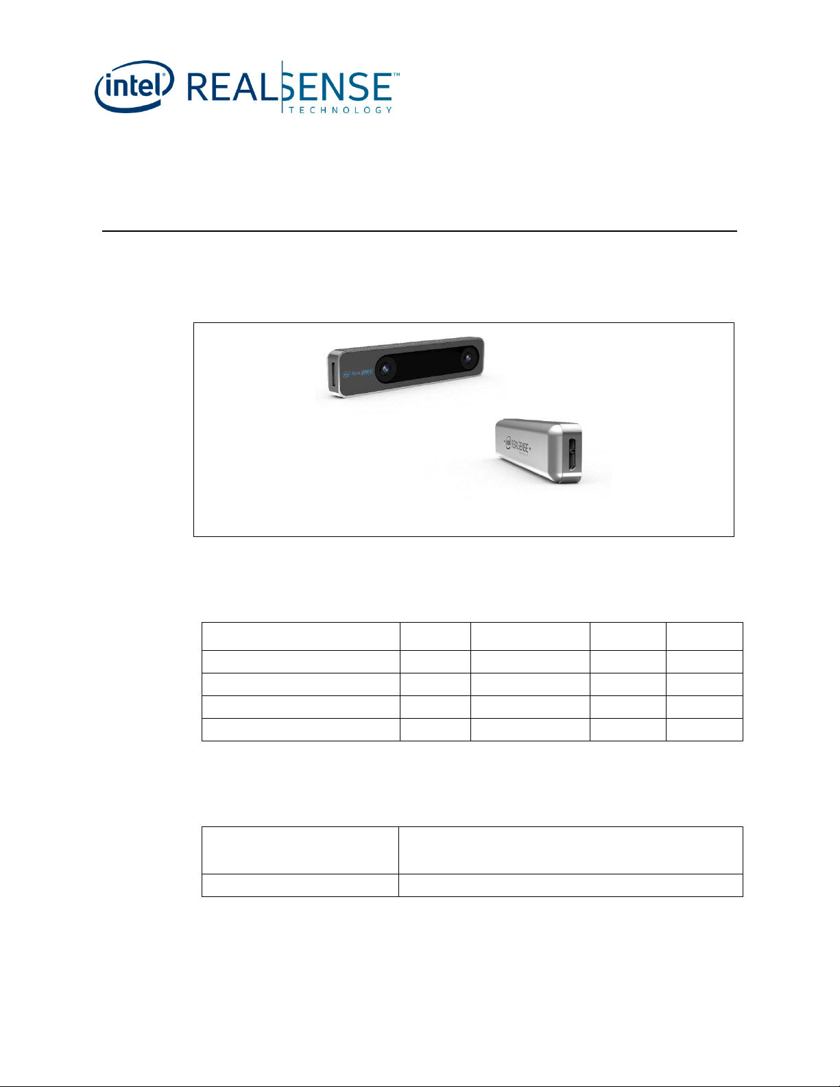
4 Intel® RealSense™ Tracking Camera T265
4.1 Intel® RealSense™ Tracking Camera T265 Device
Figure 4-1. Intel® RealSense™ Tracking Camera T265
Note: Figure may differ from final production images
4.1.1 Intel® RealSense™ Tracking Camera T265 Mechanical Dimensions
Table 4-1. Intel® RealSense™ Tracking Camera T265 Mechanical Dimensions
4.1.2 Intel® RealSense™ Tracking Camera T265 Thermals
Table 4-2. Max Skin Temperature
12 572522-002
Page 13
Condition
Description
Min
Max
Unit
Storage (Still Air), Not Operating
Temperature (Sustained, Controlled)
(1)
0
40
o
C
Temperature (Short Exposure)
(2)
-30
65
o
C
Humidity, Non-Condensing
90% RH, 30oC
Operating(3) (Still Air)
Temperature
0
35
o
C
Production
Product Material Code
Tracking Camera T265
999AXJ
Intel® RealSense™ Tracking Camera T265
4.1.3 Intel® RealSense™ Tracking Camera T265 Storage and Operating Conditions
Table 4-3. Storage and Operating Conditions
NOTES:
1. Controlled conditions should be used for long term storage of product.
2. Short exposure represents temporary max limits acceptable for transportation conditions.
3. Component case temperature limits must be met for all operating temperatures.
4.1.4 Product Identifier and Material Code
Table 4-4. Product Identifier and Material Code
4.2 T265 Center of Tracking Location
The user of the T265 device must take into consideration the location of tracking as it
pertains to the PCB inside chassis and the relationship this location has with respect to
the overall peripheral camera device. The center of tracking corresponds to the center
location between the right and left imagers on the PCB. The information in the figure
below shows the different mechanical distances of the chassis that houses the PCB. The
center of tracking information also pertains to the coordinate system which will be
discussed in future section in this document.
572522-002 13
Page 14

Figure 4-2. Center of Tracking Location
Intel® RealSense™ Tracking Camera T265
4.3 Coordinate System
Figure 4-3. T265 Coordinate System
Notes:
1. Positive X direction is towards right imager (same for world coordinates)
2. Positive Y direction is upwards toward the top of the device (same for world coordinates)
3. Positive Z direction is inwards toward the back of the device (same for world coordinates)
14 572522-002
Page 15

Description
VID
PID
Movidius Device
03E7
2150
Intel® RealSense™ Tracking
Camera T265
8087
0B37
Intel® RealSense™ Tracking Camera T265
4.4 Boot Device Information
Table 4-5: Boot Device Vendor and Product IDs
1. If T265 is being connected to host system via USB hub, keep in mind that T265 will enter into USB enumeration
protocol as soon as 5V has been provided on VBUS pin. USB protocol is handled by the Movidius MA215x device.
2. <1% drift observed in repeated testing in multiple use cases and environments. AR/VR use cases were tested with the
T265 mounted on the head in indoor living and office areas with typical indoor lighting including sunlight entering the
room. Wheeled robot use cases tested with wheel odometer data integrated, in indoor office and home environments.
Sufficient visibility of static tracked visual features is required, the device will not work in smoke, fog, or other conditions
where the camera cannot observe visual reference points. Performance will vary across use cases and environments, the
system will attempt to detect and report degraded performance but may fail to do so.
§ §
572522-002 15
Page 16

5 Regulatory Compliance
System integrators should refer to their respective regulatory and
compliance owner to finalize regulatory requirements for a specific
geography.
Do not power on the product if any external damage was observed.
Do not try to update camera firmware that is not officially released for
specific camera module SKU and revision.
Regulatory Compliance
5.1 Manufacturer’s Information
Manufactured by Intel Corporation
Attn: Corp. Quality
2200 Mission College Blvd., Santa Clara, CA 95054 USA
EU Single Place of Contact:
Attn: Corp Quality
Intel Deutschland GmbH
Am Campeon 10-12
Neubiberg, 85579 - Germany
5.2 NRTL Statement
For the US and Canada market, this product has been tested and certified by Nemko,
and found to be compliant with all applicable requirements of the specifications below.
UL 60950-1 2nd Edition, CAN/CSA C22.2 No. 60950-1-07, Information Technology
Equipment – Safety – Part 1: General Requirements
16 572522-002
Page 17

https://www.nemko.com/certification/productcertification/certificates
部件名称
Component Name
有毒有害物质或元素 Hazardous Substance
铅
Pb
汞
Hg
镉
Cd
六价铬
Cr (VI)
多溴联苯
PBB
多溴二苯醚
PBDE
相机
Camera
X
○
○
○
○
○
印刷电路板组件
Printed Board Assemblies
X
○
○
○
○
○
电缆
Cable
○
○
○
○
○
○
60950
Regulatory Compliance
Nemko is a Nationally Recognized Testing Laboratory (NRTL), recognized by US
Occupational Safety and Health Administration (OSHA) as qualified to perform safety
testing and certifications covered within its scope of recognition.
Figure 5-1. NRTL Certification
5.3 Ecology Compliance
5.3.1 RoHS Declaration
China RoHS Declaration
产品中有毒有害物质的名称及含量
Hazardous Substances Table
572522-002 17
Page 18

Regulatory Compliance
○:表示该有毒有害物质在该部件所有均质材料中的含量均在 GB/T 26572 标准规定的限量要求以下。
○:Indicates that this hazardous substance contained in all homogeneous materials of such
component is within the limits specified in GB/T 26572.
×:表示该有毒有害物质至少在该部件的某一均质材料中的含量超出 GB/T 26572 标准规定的限量要求。
×: Indicates that the content of such hazardous substance in at least a homogeneous material of
such component exceeds the limits specified in GB/T 26572.
对销售之日的所售产品,本表显示我公司供应链的电子信息产品可能包含这些物质。注意:在所售产品中
可能会也可能不会含有所有所列的部件。
This table shows where these substances may be found in the supply chain of our electronic
information products, as of the date of sale of the enclosed product. Note that some of the
component types listed above may or may not be a part of the enclosed product.
除非另外特别的标注,此标志为针对所涉及产品的环保使用期限标志. 某些可更换的零部件可能会有一个
不同的环保使用期限(例如,电池单元模块).
此环保使用期限只适用于产品在产品手册中所规定的条件下工作.
The Environment-Friendly Use Period (EFUP) for all enclosed products and their parts are per the
symbol shown here, unless otherwise marked. Certain field-replaceable parts may have a
different EFUP (for example, battery modules) number. The Environment-Friendly Use Period is
valid only when the product is operated under the conditions defined in the product manual.
§ §
18 572522-002
 Loading...