

Page 1

Document Number: 337029-007
Intel® RealSense
TM
D400 Series Product Family
Datasheet
Intel® RealSense™ Vision Processor D4, Intel® RealSense™ Vision
Processor D4 Board, Intel® RealSense™ Depth Module D400, Intel®
RealSense™ Depth Module D410, Intel® RealSense™ Depth Module D415,
Intel® RealSense™ Depth Camera D415, Intel® RealSense™ Depth Module
D420, Intel® RealSense™ Depth Module D430, Intel® RealSense™ Depth
Camera D435, Intel® RealSense™ Depth Camera D435i
Revision 007
October 2019
Page 2

2 337029-007
Intel products described herein. You agree to grant Intel a non-exclusive, royalty-free license to any patent claim thereafter
drafted which includes subject matter disclosed herein.
No license (express or implied, by estoppel or otherwise) to any intellectual property rights is granted by this document.
Intel technologies’ features and benefits depend on system configuration and may require enabled hardware, software or service
activation. Performance varies depending on system configuration. No computer system can be absolutely secure. Check with
your system manufacturer or retailer or learn more at intel.com.
Intel technologies may require enabled hardware, specific software, or services activation. Check with your system manufacturer
or retailer.
The products described may contain design defects or errors known as errata which may cause the product to deviate from
published specifications. Current characterized errata are available on request.
Intel disclaims all express and implied warranties, including without limitation, the implied warranties of merchantability, fitness
for a particular purpose, and non-infringement, as well as any warranty arising from course of performance, course of dealing, or
usage in trade.
All information provided here is subject to change without notice. Contact your Intel representative to obtain the latest Intel
product specifications and roadmaps.
Copies of documents which have an order number and are referenced in this document may be obtained by calling 1-800-5484725 or visit www.intel.com/design/literature.htm.
Intel and the Intel logo, Intel® Core™, Intel® Atom™, trademarks of Intel Corporation in the U.S. and/or other countries.
*Other names and brands may be claimed as the property of others.
© 2019 Intel Corporation. All rights reserved.
Page 3

Description and Features
337029-007 3
Contents
1 Description and Features .................................................................................. 12
2 Introduction .................................................................................................... 13
2.1 Purpose and Scope of this Document ....................................................... 13
2.2 Terminology ......................................................................................... 13
2.3 Stereo Vision Depth Technology Overview ................................................ 14
2.4 Camera System Block Diagram ............................................................... 16
2.5 Intel® RealSense™ Depth Module D400 series Product SKUs ...................... 17
2.6 Intel® RealSense™ Depth Camera D400 series Product SKUs ..................... 17
3 Component Specification .................................................................................. 19
3.1 Vision Processor D4 Camera System Components ..................................... 19
3.2 Host Processor ..................................................................................... 19
3.3 Intel® RealSense™ Vision Processor D4 ................................................... 19
3.3.1 Vision Processor D4 Features .................................................... 19
3.3.2 Vision Processor D4 Signal Description ....................................... 20
3.3.3 Vision Processor D4 Package Mechanical Attributes ...................... 25
3.3.4 Vision Processor D4 Power Requirements .................................... 31
3.3.5 Vision Processor D4 Power Sequencing ....................................... 31
3.3.6 Vision Processor D4 Spec Code .................................................. 32
3.3.7 Vision Processor D4 Storage and Operating Conditions ................. 32
3.3.8 Vision Processor D4 Thermals ................................................... 33
3.4 Clock ................................................................................................... 33
3.5 Serial (SPI) Flash Memory ...................................................................... 33
3.6 Stereo Depth Module ............................................................................. 33
3.6.1 Left and Right Imagers ............................................................. 35
3.6.2 Infrared Projector .................................................................... 36
3.6.3 Color Sensor ........................................................................... 37
3.6.4 Depth Module Connector .......................................................... 38
3.6.5 Stereo Depth Module Label ....................................................... 38
3.6.6 Stiffener ................................................................................. 39
3.6.7 Temperature Sensor ................................................................ 39
3.6.8 Other Stereo Depth Module Components .................................... 39
3.6.9 Mechanical Dimensions ............................................................. 40
3.6.10 Stereo Depth Module Power Sequence........................................ 41
3.6.11 Stereo Depth Module Storage and Operating Conditions ............... 41
3.7 Intel® RealSense™ Vision Processor D4 Board .......................................... 42
3.7.1 Mechanical Dimensions ............................................................. 43
3.7.2 Depth Module Receptacle .......................................................... 43
3.7.3 Flex and Rigid Interposer Interconnect ....................................... 43
3.7.4 External Sensor Sync Connector ................................................ 48
3.7.5 USB Peripheral Connector – Type-C ........................................... 48
3.7.6 Color Image Signal Processor (ISP) ............................................ 50
3.7.7 Vision Processor D4 Board Power Requirements .......................... 50
3.7.8 Vision Processor D4 Board Thermals .......................................... 50
3.7.9 Vision Processor D4 Board Storage and Operating Conditions ........ 51
3.7.10 Intel® RealSense™ Vision Processor D4 Board Product Identifier and
Material Code .......................................................................... 51
3.8 Intel® RealSense™ Depth Camera D400 Series ......................................... 51
Page 4

4 337029-007
3.8.1 Depth Camera D400 Series Mechanical Dimensions ..................... 52
3.8.2 Depth Camera D400 Series Thermals ......................................... 53
3.8.3 Depth Camera D400 Series Storage and Operating Conditions ...... 53
(1) Controlled conditions should be used for long term storage of product. (2)
Short exposure represents temporary max limits acceptable for
transportation conditions. ......................................................... 54
3.8.4 Depth Camera D400 Series Product Identifier and Material Code ... 54
3.8.5 Camera Lens Cleaning Procedure ............................................... 54
4 Functional Specification .................................................................................... 55
4.1 Vendor Identification (VID) and Device Identification (DID) ........................ 55
4.2 Vision Processor D4 Data Streams .......................................................... 55
4.3 Depth Field of View (FOV) ...................................................................... 58
4.4 Depth Field of View at Distance (Z) ......................................................... 58
4.5 Invalid Depth Band ............................................................................... 59
4.6 Minimum-Z Depth ................................................................................. 61
4.7 Depth Quality Specification .................................................................... 61
4.8 Measured Power ................................................................................... 63
4.9 Depth Start Point (Ground Zero Reference) .............................................. 64
4.9.1 Depth Origin X-Y Coordinates .................................................... 66
4.10 Depth Camera Functions ........................................................................ 67
4.11 Color Camera Functions ......................................................................... 68
4.12 IMU Specifications ................................................................................. 69
5 Firmware ........................................................................................................ 70
5.1 Update ................................................................................................ 70
5.1.1 Update Limits .......................................................................... 70
5.2 Recovery ............................................................................................. 70
6 Software ......................................................................................................... 71
6.1 Intel® RealSense™ Software Development Kit 2.0 ..................................... 71
7 System Integration .......................................................................................... 72
7.1 System Level Block Diagram .................................................................. 72
7.2 Vision Processor D4 System Integration ................................................... 72
7.2.1 Vision Processor D4 Board ........................................................ 72
7.2.2 Vision Processor D4 on Motherboard .......................................... 73
7.3 D4 Camera System Power Delivery ......................................................... 74
7.4 Vision Processor D4 Board for Integrated Peripheral .................................. 75
7.4.1 USB 3.1 Gen 1 Receptacle ........................................................ 75
7.4.2 USB 3.1 Gen 1 High Speed Cable Assembly ................................ 75
7.4.3 Transmit to Receive Crossover .................................................. 76
7.4.4 Motherboard Receptacle ........................................................... 77
7.4.5 Vision Processor D4 Board for Integrated Peripheral Power
Requirements .......................................................................... 77
7.5 Thermals ............................................................................................. 77
7.6 Stereo Depth Module Flex ...................................................................... 79
7.7 Stereo Depth Module Mounting Guidance ................................................. 79
7.7.1 Screw Mount ........................................................................... 79
7.7.2 Bracket Mount ......................................................................... 80
7.7.3 Stereo Depth Module Air gap ..................................................... 81
7.8 Thermal Interface Material ..................................................................... 82
7.9 Heat Sink ............................................................................................. 82
Page 5

Description and Features
337029-007 5
7.10 Cover Design and Material Guidance ....................................................... 82
7.11 Gaskets ............................................................................................... 83
7.11.1 Optical Isolation ...................................................................... 84
7.11.2 Dust Protection ....................................................................... 85
7.12 Firmware Recovery ............................................................................... 85
7.13 Calibration Support ............................................................................... 86
7.14 Multi-Camera Hardware Sync ................................................................. 86
7.15 Handling Conditions .............................................................................. 87
8 Platform Design Guidelines ............................................................................... 88
8.1 Vision Processor D4 on Motherboard ....................................................... 88
8.2 Kaby Lake U and Kaby Lake Y platforms .................................................. 89
8.2.1 Kaby Lake Platform Introduction ................................................ 89
8.2.2 Supported PCB Stack-Up and Routing Geometries ....................... 89
8.2.3 Vision Processor D4 on Motherboard with USB Host Interface ........ 90
8.2.4 Vision Processor D4 on Motherboard with MIPI Host Interface ....... 91
8.2.5 Vision Processor D4 Board for Integrated Peripheral (USB 3.1 Gen 1
Host to Vision Processor D4 Routing) ......................................... 93
8.2.6 USB2.0 Design Guidelines (USB2 Host to Vision Processor D4
Routing) ................................................................................. 94
8.3 Cherry Trail T4 Platform ......................................................................... 95
8.3.1 Cherry Trail T4 Platform Introduction ......................................... 95
8.3.2 Vision Processor D4 Platform Design Guidelines ........................... 95
9 Regulatory Compliance ..................................................................................... 96
9.1 System Laser Compliance ...................................................................... 96
9.1.1 Certification Statement............................................................. 96
9.1.2 Explanatory Label .................................................................... 96
9.1.3 Cautionary Statements ............................................................. 96
9.1.4 Manufacturer’s Information ....................................................... 97
9.1.5 US FDA Accession Number ........................................................ 97
9.1.6 NRTL Statement ...................................................................... 97
9.2 Ecology Compliance .............................................................................. 98
9.2.1 China RoHS Declaration ............................................................ 98
9.2.2 Waste Electrical and Electronic Equipment (WEEE) ....................... 99
10 Mechanical Drawings ....................................................................................... 100
11 Connector Drawings ........................................................................................ 108
12 Appendix A – Vision Processor D4 on Motherboard Schematic Checklist ................. 110
12.1 Power Delivery .................................................................................... 117
13 Appendix B- Cover Material .............................................................................. 120
Figures
Figure 2-1. Active Infrared (IR) Stereo Vision Technology ......................................................... 15
Figure 2-2. Depth Measurement (Z) versus Range (R) .............................................................. 15
Figure 2-3. Vision Processor D4 Camera System Block Diagram ................................................ 16
Figure 3-1. Vision Processor D4 Package Drawing .................................................................... 27
Figure 3-2. Vision Processor D4 Ball-out ................................................................................. 28
Page 6

6 337029-007
Figure 3-3. Vision Processor D4 Power Sequencing .................................................................. 32
Figure 3-4. Stereo Depth Module (Intel® RealSense™ Depth Module D410)................................. 34
Figure 3-5. Stereo Depth Module (Intel® RealSense™ Depth Module D430)................................. 34
Figure 3-6. Stereo Depth Module Power Sequence ................................................................... 41
Figure 3-7. Vision Processor D4 Board (USB Peripheral Type-C)................................................. 42
Figure 3-8. Flex Interposer (Illustration) ................................................................................. 44
Figure 3-9. Rigid Interposer (Illustration) ............................................................................... 44
Figure 3-10. Depth Module Receptacle and Plug Connector Pin Position ...................................... 45
Figure 3-11. Depth Module Connector Orientation and Pin Position ............................................. 47
Figure 3-12. USB Type-C Receptacle Pin Map .......................................................................... 49
Figure 3-13. Intel® RealSenseTM Depth Camera D415 ............................................................... 51
Figure 3-14. Intel® RealSense™ Depth Camera D435/D435i ..................................................... 52
Figure 4-1. Depth Field of View to Depth Map illustration .......................................................... 59
Figure 4-2. Left Invalid Depth Band ....................................................................................... 60
Figure 4-3. Depth Module Depth Start Point Reference ............................................................. 64
Figure 4-4. Depth Camera Depth Start Point Reference ............................................................ 65
Figure 4-5. Depth Module X-Y Depth Origin Reference .............................................................. 66
Figure 4-6. Depth Camera X-Y Depth Origin Reference ............................................................. 67
Figure 7-1. System Block Diagram ......................................................................................... 72
Figure 7-2. Intel® RealSense™ Vision Processor D4 Board ........................................................ 73
Figure 7-3. Vision Processor D4 on Motherboard (Illustration) ................................................... 73
Figure 7-4. D4 Camera System Power Scheme ........................................................................ 74
Figure 7-5. Host Motherboard USB 3.1 Gen 1 Routing .............................................................. 76
Figure 7-6. Receptacle Ground Bar Motherboard Connections .................................................... 77
Figure 7-7. Bottom Stiffener Depth Module D410 ..................................................................... 79
Figure 7-8. Bottom Stiffener Depth Module D430 ..................................................................... 79
Figure 7-9. Stereo Depth Module Screw Mount ........................................................................ 80
Figure 7-10. Stereo Depth Module Bracket .............................................................................. 80
Figure 7-11. Stereo Depth Module Bracket Mount .................................................................... 81
Figure 7-12. Stereo Depth Module Bracket Install .................................................................... 81
Figure 7-13. Stereo Depth Module Air Gap .............................................................................. 82
Figure 7-14. Illustration of Gasket Placement and Cover Material ............................................... 84
Figure 7-15. Example of Light Leakage Effects......................................................................... 85
Figure 7-16. Firmware Recovery Sequence ............................................................................. 86
Figure 7-17. External Sensor Sync Connector Location on D4 Vision Processor D4 Board .............. 86
Figure 7-18. External Sensor Sync Connector Location on Depth Camera D435/D435i .................. 87
Figure 8-1. Vision Processor D4 with USB Host Interface .......................................................... 88
Figure 8-2. Vision Processor D4 with MIPI Host Interface .......................................................... 88
Figure 8-3. Vision Processor D4 on Board for USB Integrated Peripheral ..................................... 89
Figure 8-4. Host Processor - Vision Processor D4 ..................................................................... 90
Figure 8-5. Vision Processor D4 Transmit - Host Receive ......................................................... 91
Figure 8-6. Stereo Depth Transmit - Vision Processor D4 Receive .............................................. 92
Figure 8-7. Flex Interposer PCB Stack-Up ............................................................................... 93
Figure 8-8. USB 3.1 Gen 1 Host to Vision Processor D4 Topology ............................................... 93
Figure 8-9. USB2.0 Host to Vision Processor D4 ....................................................................... 94
Figure 9-1. NRTL Certifications .............................................................................................. 98
Figure 10-1. Intel® RealSense™ Depth Module D400 ............................................................... 100
Figure 10-2. Intel® RealSense™ Depth Module D410 ............................................................... 101
Figure 10-3. Intel® RealSense™ Depth Module D415 ............................................................... 102
Figure 10-4. Intel® RealSense™ Depth Module D420 ............................................................... 103
Figure 10-5. Intel® RealSense™ Depth Module D430 ............................................................... 104
Figure 10-6. Vision Processor D4 Board USB Type-C (Intel® RealSense™ Vision Processor D4 Board)
.................................................................................................................... 105
Figure 10-7. Intel® RealSense™ Depth Camera D415 .............................................................. 106
Figure 10-8. Intel® RealSense™ Depth Camera D435/D435i .................................................... 107
Page 7

Description and Features
337029-007 7
Figure 11-1. Receptacle Mechanical Drawing (50 Pin Depth Module Receptacle).......................... 108
Figure 11-2. Plug Mechanical Drawing (50 pin Depth Module Plug) ............................................ 109
Figure 12-1. Vision Processor D4 Laser PWM Reference Platform Schematic ............................... 117
Figure 12-2. Vision Processor D4 24MHz Crystal Clock Reference Platform Schematic .................. 117
Figure 12-3. DC-DC Reference Platform Schematic (3.3V, 1.8V, 0.9V) ....................................... 118
Figure 12-4. Vision Processor D4 VDD_PG and AVDD Reference Platform Schematic ................... 119
Tables
Table 2-1. Depth Module Product SKU Descriptions .................................................................. 17
Table 2-2. Depth Camera Product SKU Descriptions ................................................................. 18
Table 3-1. Component Descriptions ........................................................................................ 19
Table 3-2. Vision Processor D4 Signal Descriptions .................................................................. 20
Table 3-3. Hardware Straps .................................................................................................. 25
Table 3-4. Vision Processor D4 Package Mechanical Attributes ................................................... 26
Table 3-5. Vision Processor D4 Ball-out by Signal Name ........................................................... 28
Table 3-6. Vision Processor D4 Power Requirements ................................................................ 31
Table 3-7. Vision Processor D4 Power Sequencing Timing Parameters ........................................ 31
Table 3-8. Vision Processor D4 SPEC Code .............................................................................. 32
Table 3-9. Vision Processor D4 Storage and Operating Conditions .............................................. 32
Table 3-10. Stereo Depth Module........................................................................................... 33
Table 3-11. Stereo Depth Module SKU Properties ..................................................................... 34
Table 3-12. Standard Left and Right Imager Properties ............................................................ 35
Table 3-13. Wide Left and Right Imager Properties .................................................................. 35
Table 3-14. Standard Infrared Projector Parameters ................................................................ 36
Table 3-15. Wide Infrared Projector Parameters ...................................................................... 36
Table 3-16. Color Sensor Properties ....................................................................................... 37
Table 3-17. Depth Module 50-pin Connector Plug Details .......................................................... 38
Table 3-18. Stereo Depth Module Product Labeling .................................................................. 38
Table 3-19. Stereo Depth Module Label Fields ......................................................................... 38
Table 3-20. Intel® RealSense™ Depth Module D400 Series Product Identifier Code and Product
Material Code .................................................................................................. 39
Table 3-21. Other Stereo Depth Module Components ............................................................... 39
Table 3-22. Intel® RealSense™ Depth Module D400 Mechanical Dimensions ............................... 40
Table 3-23. Intel® RealSense™ Depth Module D410 Mechanical Dimensions ............................... 40
Table 3-24. Intel® RealSense™ Depth Module D415 Mechanical Dimensions ............................... 40
Table 3-25. Intel® RealSense™ Depth Module D420 Mechanical Dimensions ............................... 40
Table 3-26. Intel® RealSense™ Depth Module D430 Mechanical Dimensions ............................... 41
Table 3-27. Stereo Depth Module Storage and Operating Conditions .......................................... 41
Table 3-28. Vision Processor D4 Board .................................................................................. 42
Table 3-29. Vision Processor D4 Board Components ................................................................. 42
Table 3-30. Vision Processor D4 USB Type-C Board Mechanical Dimensions ................................ 43
Table 3-31. Depth Module Receptacle Details .......................................................................... 43
Table 3-32. Interposer Interconnect Signal Description............................................................ 45
Table 3-33. Custom Flex Interposer Ordering Logistics ............................................................. 47
Table 3-34. External Sensor Connector Details ........................................................................ 48
Table 3-35. External Sensor Sync Connector Pin List ................................................................ 48
Table 3-36. USB Peripheral Connector Pin List ......................................................................... 49
Table 3-37. Custom USB Type C cable Assemblies Ordering Logistics ......................................... 50
Table 3-38. ISP Properties .................................................................................................... 50
Table 3-39. Vision Processor D4 Board Power Requirements ..................................................... 50
Table 3-40. Vision Processor D4 Board Storage and Operating Conditions ................................... 51
Table 3-41. Vision Processor D4 Board Product Identifier and Material Code ................................ 51
Page 8

8 337029-007
Table 3-42. Depth Camera SKU properties .............................................................................. 52
Table 3-43. Intel® RealSense™ Depth Camera D415 Mechanical Dimensions ............................... 52
Table 3-44. Intel® RealSense™ Depth Camera D435, D435i Mechanical Dimensions .................... 53
Table 3-45. Max Skin Temperature ........................................................................................ 53
Table 3-46. Depth Camera D400 Series Storage and Operating Conditions ................................. 53
Table 3-47. Depth Camera D400 Series Product Identifier and Material Code .............................. 54
Table 4-1. Vendor ID and Device ID Table .............................................................................. 55
Table 4-2. Image Formats (USB 3.1 Gen1) ............................................................................. 55
Table 4-3. Image Formats (USB 2.0) ...................................................................................... 56
Table 4-4. Simultaneous Image Streams (USB 3.1 Gen1 & USB2.0) ........................................... 57
Table 4-5. Depth Field of View ............................................................................................... 58
Table 4-6. Minimum-Z Depth ................................................................................................ 61
Table 4-7: Depth Quality Metric ............................................................................................. 61
Table 4-8: Depth Quality Metric Illustration ............................................................................. 62
Table 4-9. Depth Quality Specification .................................................................................... 62
Table 4-10. Power- Ubuntu 16.04 .......................................................................................... 63
Table 4-11. Power – Windows 10 (RS4) .................................................................................. 63
Table 4-12. Depth Module Depth Start Point .......................................................................... 64
Table 4-13. Depth Cameras Depth Start Point ........................................................................ 65
Table 4-14. Depth Module X-Y Depth Origin Coordinates.......................................................... 66
Table 4-15. Depth Camera X-Y Depth Origin Coordinates ......................................................... 67
Table 4-16. Depth Camera Controls ....................................................................................... 67
Table 4-17. RGB Exposed Controls ......................................................................................... 68
Table 4-18. IMU Specifications .............................................................................................. 69
Table 7-1. USB 3.1 Gen 1 Receptacle Characteristics................................................................ 75
Table 7-2. USB 3.1 Gen 1 Receptacle Pin Out .......................................................................... 75
Table 7-3. USB 3.1 Gen 1 Plug Characteristics ......................................................................... 75
Table 7-4. Cable Assembly Specification ................................................................................. 76
Table 7-5. Motherboard Receptacle Properties ......................................................................... 77
Table 7-6. Vision Processor D4 Board as Embedded Peripheral Power Requirements .................... 77
Table 7-7. Vision Processor D4 Board – Component Power and TDP at Max Operating Mode
(1)
....... 78
Table 7-8. Stereo Depth Module (Standard) – Component Power and TDP at Max Operating Mode
(1)
..................................................................................................................... 78
Table 7-9. Stereo Depth Module (Wide) – Component Power and TDP at Max Operating Mode
(1)
.... 78
Table 7-10. Vision Processor D4 Board Components – Case Temperature Limits (Still Air) ............ 78
Table 7-11. Component Transmission ..................................................................................... 83
Table 7-12. Electrostatic Discharge Caution ............................................................................ 87
Table 8-1. Host Transmit – Vision Processor D4 Receive Routing Guidelines ................................ 90
Table 8-2. Vision Processor D4 Transmit - Host Receive Routing Guidelines ................................ 90
Table 8-3. Vision Processor D4 Transmit – Host Receive Routing Guidelines ................................ 91
Table 8-4. Stereo Depth Module Transmit - Vision Processor D4 Receive Routing Guidelines ........ 92
Table 8-5. USB 3.1 Gen 1 Host to Vision Processor D4 Routing Guidelines ................................. 94
Table 9-1. U.S. FDA Accession Number................................................................................... 97
Table 12-1. Vision Processor D4 on Motherboard Schematic Checklist ....................................... 110
Table 12-2. Vision Processor D4 Decoupling and Filter Requirements ........................................ 119
Table 13-1. Example: Cover Material Parameters .................................................................... 120
Page 9

Description and Features
337029-007 9
Revision History
Document Number
Revision Number
Description
Revision Date
337029
001
Initial release
January 2018
002
Tracking Module 1 removal, NRTL
certification, 7.2.2.1 Firmware Update
March 2018
003
• Added USB2.0 support
• Removed VBUS0 from Table 3 6.Vision
Processor D4 Power Requirements
• Table 3 12. Standard Left and Right
Imager Properties
• Table 3 13. Wide Left and Right
Imager Properties
• Table 3 9. Vision Processor D4 Storage
and Operating Conditions
• Table 3 27 Stereo Depth Module
Storage and Operating Conditions
• Table 3 38. Vision Processor D4 Board
Storage and Operating Conditions
• Table 3 44. Depth Camera D400 Series
Storage and Operating Conditions
• Table 4 3. Image Formats (USB 2.0)
• Table 4 5. Simultaneous Image
Streams (USB3.1 Gen1, USB 2.0)
• 4.7 Depth Origin Point (Ground Truth
Zero)
• 7.14 Multi-Camera hardware sync for
multi-camera configuration
July 2018
Page 10

10 337029-007
Document Number
Revision Number
Description
Revision Date
004
• Description and Features
• Terminology
• Table 2-2. Depth Camera Product SKU
Descriptions
• Table 3-11. Stereo Depth Module SKU
Properties
• Table 3-33. Custom Flex Interposer
Ordering Logistics
• Table 3-35. External Sensor Sync
Connector Pin List
• Table 3-42. Depth Camera SKU
properties
• Table 3-47. Depth Camera D400 Series
Product Identifier and Material
Code
• Table 4-1. Vendor ID and Device ID
Table
• Table 4-2. Image Formats (USB 3.1
Gen1)
• Table 4-3. Image Formats (USB 2.0)
• Table 4-9. Depth Quality Specification
• Section 4-12 IMU Specification
November 2018
005
• Table 3-11. Stereo Depth Module SKU
Properties
• Table 3-42. Depth Camera SKU
Properties
• Table 4-4. Simultaneous Image
Streams (USB 3.1 Gen 1 & USB
2.0)
• Table 4-18. IMU Specifications
January 2019
006
• Table 3-28. Vision Processor D4 Board
• Table 4-2. Image Formats (USB 3.1
Gen1)
• Table 4-4. Simultaneous Image
Streams (USB 3.1 Gen1 & USB 2.0)
• Table 4-17. RGB Exposed Controls
• Figure 10-7. Intel® RealSense™ Depth
Camera D415
• Figure 10-8. Intel® RealSense™ Depth
Camera D435/D435i
• Figure 4-1. Depth Field of View to
Depth Map illustration
June 2019
Page 11

Description and Features
337029-007 11
Document Number
Revision Number
Description
Revision Date
007
• Table 3-19. Stereo Depth Module
Label Fields
• Table 3 43. Intel® RealSense™ Depth
Camera D415 Mechanical
Dimensions
• Table 3 44. Intel® RealSense™ Depth
Camera D435, D435i Mechanical
Dimensions
• Table 4-9. Depth Quality Specification
• Section 7.6. Stereo Depth Module Flex
• Remove Table 7-11. Bracket Ordering
Logistics
October 2019
§ §
Page 12

Description and Features
Datasheet 12
1 Description and Features
Description
The Intel® RealSense
TM
D400 series is a stereo
vision depth camera system. The subsystem
assembly contains stereo depth module and vision
processor with USB 2.0/USB 3.1 Gen 1 or MIPI1
connection to host processor.
The small size and ease of integration of the
camera sub system provides system integrators
flexibility to design into a wide range of products.
The Intel® RealSenseTM D400 series also offers
complete depth cameras integrating vision
processor, stereo depth module, RGB sensor with
color image signal processing and Inertial
Measurement Unit2 (IMU). The depth cameras are
designed for easy setup and portability making
them ideal for makers, educators, hardware
prototypes and software development.
The Intel® RealSenseTM D400 series is supported
with cross-platform and open source Intel®
RealSense™ SDK 2.0
Usages/Markets
• Drones
• Robots
• Home and Surveillance
• Virtual Reality
• PC Peripherals
Minimum System Requirements
USB 2.0/USB 3.1 Gen 1
Ubuntu*16.xx/Windows*10
Intel® RealSense™ Depth Camera D415
Features
• Intel® RealSense™ Vision Processor D4
• Up to 1280x720 active stereo depth resolution
• Up to 1920x1080 RGB resolution
• Depth Diagonal Field of View over 70°
• Dual rolling shutter sensors for up to 90 FPS
depth streaming
• Range 0.3m to over 10m (Varies with lighting
conditions)
Intel® RealSense™ Depth Camera
D435/D435i Features
• Intel® RealSense™ Vision Processor D4
• Up to 1280x720 active stereo depth resolution
• Up to 1920x1080 RGB resolution
• Depth Diagonal Field of View over 90°
• Dual global shutter sensors for up to 90 FPS
depth streaming
• Range 0.2m to over 10m (Varies with lighting
conditions)
• Intel® RealSense™ Depth Camera D435i
includes Inertial Measurement Unit (IMU) for 6
degrees of freedom (6DoF) data
Features
• 2nd Generation Stereo Depth Camera System
• 2nd Generation dedicated Intel® RealSense™
Vision Processor D4 with advanced algorithms
• Infrared (IR) Laser Projector System (Class 1)
• Full HD resolution Image sensors
• Active Power Management
• Selection of Stereo Depth Module options to
meet your usage requirements
1. MIPI is not currently supported. Please
contact your Intel representative on MIPI
enablement timelines.
2. Camera SKU dependent
§ §
Page 13

Introduction
337029-007 13
2 Introduction
2.1 Purpose and Scope of this Document
This document captures the specifications and the design–in details for the Intel®
RealSense™ D400 series family of products. This document provides information
necessary to understand and implement an Intel® RealSense™ D400 series based
camera system.
Note: Intel® RealSense™ D400 series is alternately referred as “D4 Camera System”
in this document. Intel® RealSense™ Vision Processor D4 is alternately referred as
“D4” in this document.
2.2 Terminology
Term
Description
6DOF
Six degrees of freedom (6DoF) refers to the freedom of movement of a rigid
body in three-dimensional space. Forward/back, up/down, left/right, pitch,
yaw, roll
Stereo Depth
Baseline
The distance between the center of the left and right imagers in a stereo
camera
MIPI CSI-2
The Camera Serial Interface (CSI) is a specification of the Mobile Industry
Processor Interface (MIPI) Alliance and CSI-2 is the 2nd generation
specification defining the interface between a camera and a host processor
Depth
Depth video streams are like color video streams except each pixel has a
value representing the distance away from the camera instead of color
information
D4 (DS5)
If the term D4 is used alone, it refers to the entire D4 camera system
consisting of various modules and components.
If the term D4 is used with an appropriate qualifier (i.e. D4 Vision Processor,
D4 Vision Processor Board), it refers to the specific module or component
within the D4 camera system.
FOV
Field Of View (FOV) describes the angular extent of a given scene that is
imaged by a camera. A camera's FOV can be measured horizontally,
vertically, or diagonally
Host System
Computer or SOC connected to D4 camera
I2C
I²C (Inter-Integrated Circuit), pronounced I-squared-C, is a multi-master,
multi-slave, single-ended, serial computer bus invented by Philips
Semiconductor (now NXP Semiconductors). It is typically used to allow easy
control and data communication between components.
IR Projector
This refers to the source of infrared (IR) light used for illuminating a scene,
object, or person to collect depth data.
Page 14
Introduction
14 337029-007
Term
Description
Imagers
Depth camera system uses a pair of cameras referred as imagers to calculate
depth. They are identical cameras configured with identical settings.
Image Signal
Processor (ISP)
Image processing functions to enhance color image quality
Left imager
From the perspective of the stereo camera looking out at the world, the left
imager is on the left side of the camera module. Thus, when the user is
facing the D4 camera, the left imager is actually on the right side of the
camera module.
Lens
This refers to the optical component of an imager in the D4 camera. Its
purpose is to focus the incoming light rays onto the CMOS chip in the imager.
MIPI
MIPI (Mobile Industry Processor Interface) is a global, open membership
organization that develops interface specifications for the mobile ecosystem
Platform
camera
This refers to the two-dimensional (2D) color camera on platform
System On
Chip (SoC)
Integrated circuit (IC) that integrates all components of a computer
Stereo Depth
Module
This refers to a stiffened module containing at least two imagers. The
distance between the imagers, which is referred to as the baseline or
intraocular spacing, is typically in the range of 20 mm to 70 mm.
Stereo camera
This refers to a pair of imagers looking at the same subject from slightly
different perspectives. The difference in the perspectives is used to generate
a depth map by calculating a numeric value for the distance from the imagers
to every point in the scene.
SKU
Stock Keeping Unit (SKU) is a unique identifier for distinct products. It is
often used in the scope of naming different versions of a device
TBD
To Be Determined. In the context of this document, information will be
available in a later revision.
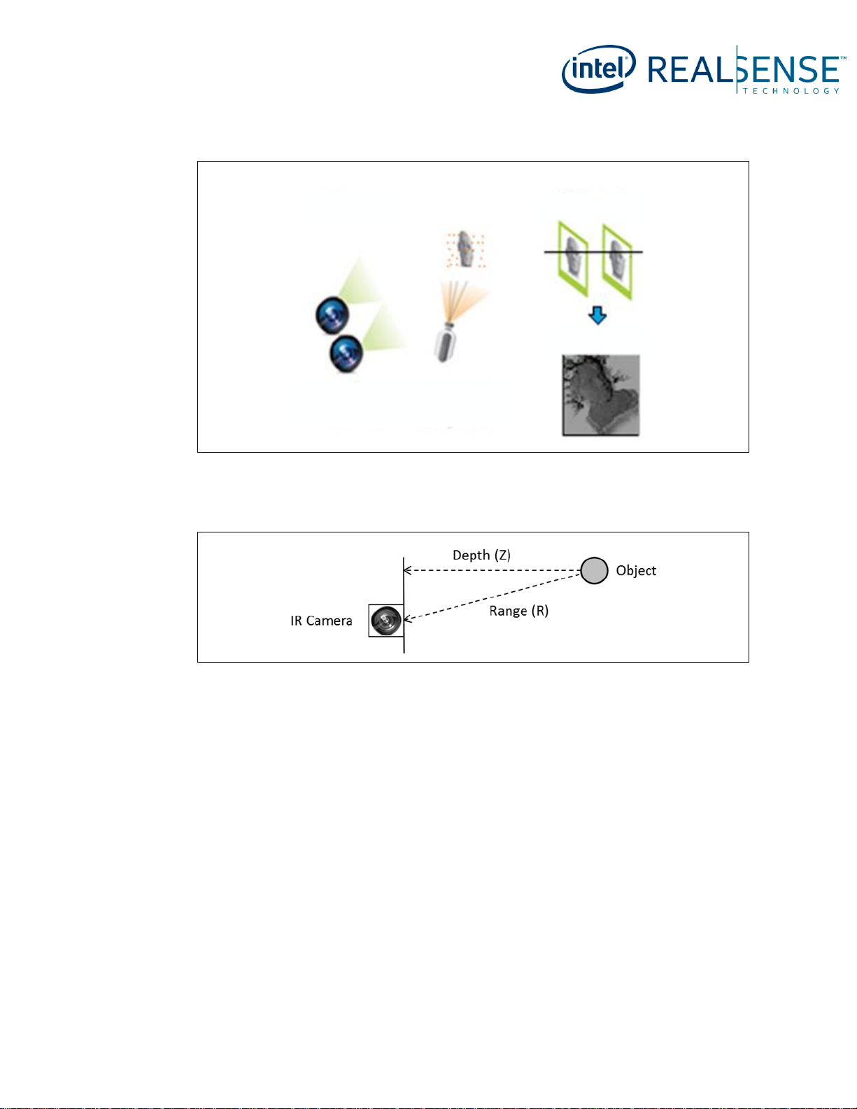
2.3 Stereo Vision Depth Technology Overview
The Intel® RealSense™ D400 series depth camera uses stereo vision to calculate
depth. The stereo vision implementation consists of a left imager, right imager, and an
optional infrared projector. The infrared projector projects non-visible static IR pattern
to improve depth accuracy in scenes with low texture. The left and right imagers
capture the scene and sends imager data to the depth imaging (vision) processor,
which calculates depth values for each pixel in the image by correlating points on the
left image to the right image and via shift between a point on the Left image and the
Right image. The depth pixel values are processed to generate a depth frame.
Subsequent depth frames create a depth video stream.
Page 15
Introduction
337029-007 15
Figure 2-1. Active Infrared (IR) Stereo Vision Technology
Image
Sensors
IR Projector
1) Capture
2) Search
3) Depth
The depth pixel value is a measurement from the parallel plane of the imagers and not
the absolute range as illustrated.
Figure 2-2. Depth Measurement (Z) versus Range (R)
Page 16
Introduction
16 337029-007
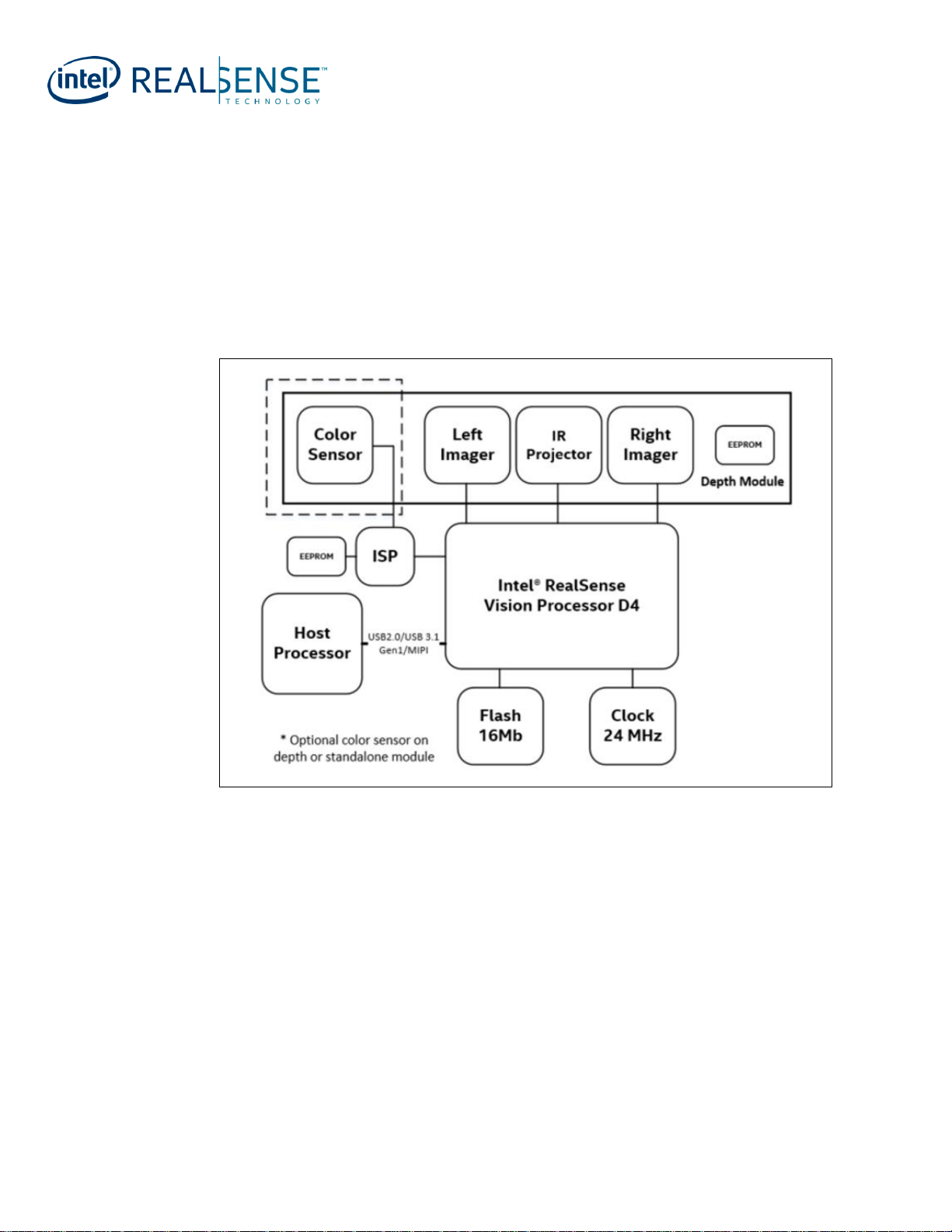
2.4 Camera System Block Diagram
The camera system has two main components, Vision processor D4 and Depth
module. The Vision processor D4 is either on the host processor motherboard or on a
discrete board with either USB2.0/USB 3.1 Gen1 or MIPI connection to the host
processor. The Depth module incorporates left and right imagers for stereo vision with
the optional IR projector and RGB color sensor. The RGB color sensor data is sent to
vision processor D4 via the color Image Signal Processor (ISP) on Host Processor
motherboard or D4 Board.
Figure 2-3. Vision Processor D4 Camera System Block Diagram
Page 17

Introduction
337029-007 17
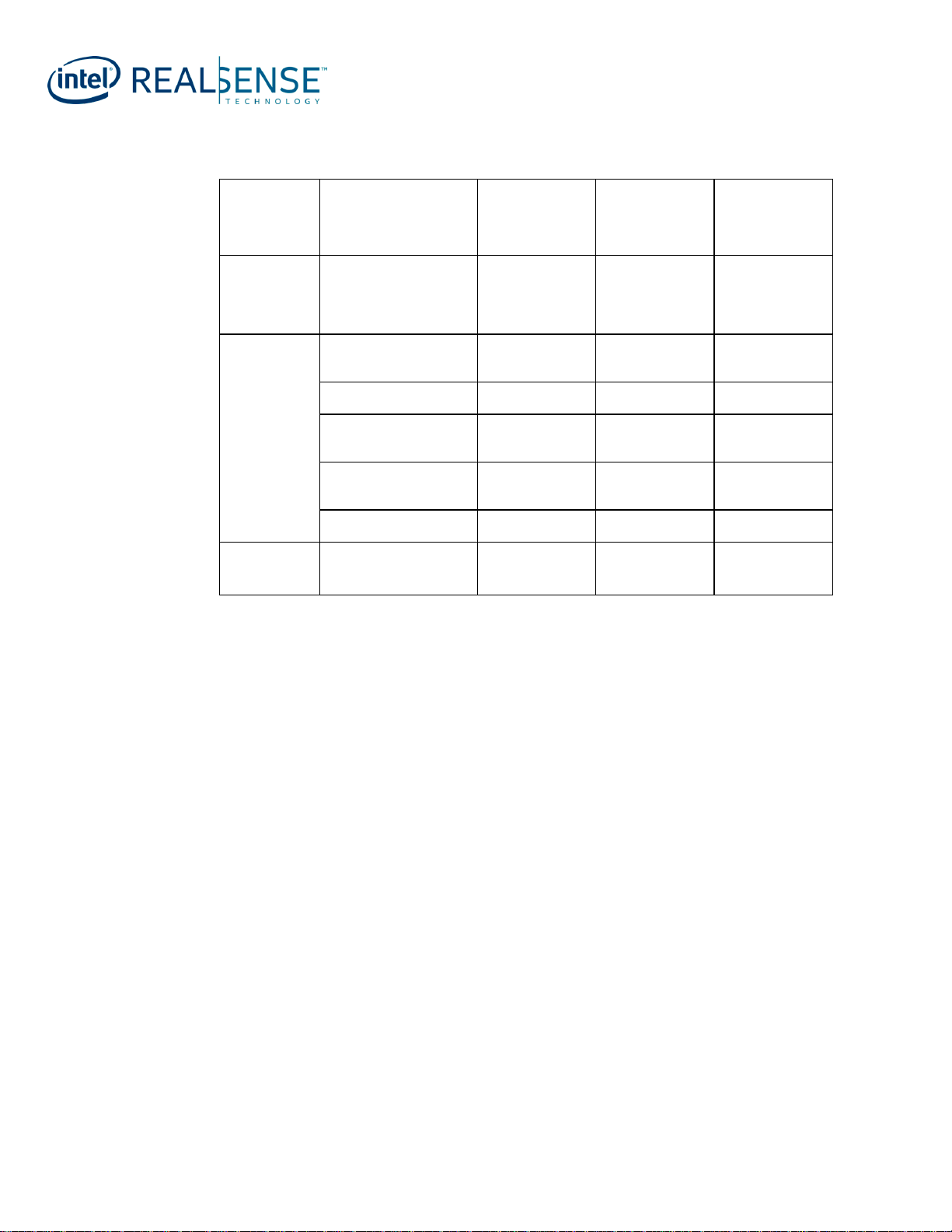
2.5 Intel
®
RealSense™ Depth Module D400 series
Product SKUs
Table below describes main components that make up the different depth module
SKUs
Table 2-1. Depth Module Product SKU Descriptions
Component
Subcomponent
D400
D410
D415
D420
D430
Intel® RealSense™
Vision Processor D4
-
√ √ √ √ √
Intel® RealSense™
Depth Module
Standard Stereo Imagers
√ √ √ X X
Wide Stereo Imagers
X X X √ √
Standard Infrared
Projector
X √ √ X X
Wide Infrared Projector
X X X X √
RGB color sensor
X X √ X X
D400 - Intel® RealSense™ Depth Module D400
D410 - Intel® RealSenseTM Depth Module D410
D415 - Intel® RealSenseTM Depth Module D415
D420 - Intel® RealSenseTM Depth Module D420
D430 - Intel® RealSenseTM Depth Module D430
2.6 Intel
®
RealSense™ Depth Camera D400 series
Product SKUs
Table below describes main components that make up the different camera SKUs:
Page 18
Introduction
18 337029-007
Table 2-2. Depth Camera Product SKU Descriptions
Component
Subcomponent
Intel®
RealSenseTM
Depth Camera
D415
Intel®
RealSenseTM
Depth Camera
D435
Intel®
RealSenseTM
Depth Camera
D435i
Intel®
RealSense™
Vision
Processor D4
-
√ √ √
Intel®
RealSense™
Depth Module
Standard Stereo
Imagers
√ X X
Wide Stereo Imagers
X √ √
Standard Infrared
Projector
√ X X
Wide Infrared
Projector
X √ √
RGB color sensor
√ √ √
Inertial
Measurement
Unit (IMU)
X X √
§ §
Page 19

Component Specification
337029-007 19
3 Component Specification
3.1 Vision Processor D4 Camera System Components
Table 3-1. Component Descriptions
Component
Description
Host Processor
Host Processor that receives Depth and other data streams from Vision
Processor D4
Vision
Processor D4
(DS5 ASIC)
Depth Imaging Processor with USB 2.0/USB 3.1 Gen 1 or MIPI interface
connection to Host Processor
Clock
24MHz clock source for Vision Processor D4
Serial Flash
Memory
SPI 16Mb Serial Flash memory for firmware storage
Stereo Depth
Module
Camera module with left and Right Imager, Color Sensor†, IR projector†
enclosed in a stiffener
Power Delivery
Circuitry on motherboard/Vision processor D4 Board to deliver and manage
power to Vision Processor D4 and Stereo Depth Module.
Stereo Depth
Connector and
Interposer
50 pin connector on motherboard/Vision Processor D4 Board and Stereo
Depth module with interposer for connection
(†) SKU dependent
3.2 Host Processor
The host processor interface to Vision Processor D4 is either USB 2.0/USB 3.1 Gen 1
or MIPI. To ensure the best of quality of service, the Vision Processor D4 must be
connected to a dedicated USB 3.1 Gen 1 root port within the host processor system.
3.3 Intel
®
RealSense™ Vision Processor D4
The primary function of Vision Processor D4 is to perform depth stereo vision
processing. The Vision Processor D4 on Host Processor motherboard or on Vision
Processor D4 Board communicates to the host processor through USB2.0/USB 3.1 Gen
1 or MIPI and receives sensor data from stereo depth module. The Vision Processor
D4 supports MIPI CSI-2 channels for connection to image sensors.
3.3.1 Vision Processor D4 Features
• 28nm Process Technology.
Page 20
Component Specification
20 337029-007
• 5 MIPI camera ports with each MIPI lane capable of handling data transfers of up
to 750 Mbps.
• USB2.0/USB 3.1 Gen 1 or MIPI interface to host system.
• Image rectification for camera optics and alignment compensation
• IR Projector (Laser) controls
• Serial Peripheral Interface for fast data transfer with external SPI flash.
• Integrated I2C ports
• General purpose Input Output pins
• Active power gating
3.3.2 Vision Processor D4 Signal Description
Table 3-2. Vision Processor D4 Signal Descriptions
RESERVED – Signal reserved for future usage
IO Type- Input Output Buffer type
A – Analog
I – Input
O - Output
Signal Name
Description
IO
Type
After
RESET
Host MIPI
H_DATAP0
H_DATAN0
Host MIPI Data Lane 0 Differential Pair
A
I
H_DATAP1
H_DATAN1
Host MIPI Data Lane 1 Differential Pair
A
I
H_DATAP2
H_DATAN2
Host MIPI Data Lane 2 Differential Pair
A
I
H_DATAP3
H_DATAN3
Host MIPI Data Lane 3 Differential Pair
A
I
H_CLKP
H_CLKN
Host MIPI Clock Differential Transmit Pair
A
I
H_SDA
H_SCL
Host I2C Bus Data and Clock
I/O
IO
H_REXT
Host MIPI External Reference 6.04K 1% resistor pull down
to ground)
A
I
Imager A MIPI
A_DATAP0
A_DATAN0
Imager A MIPI Data Lane 0 Differential Receive Pair
A
I
A_DATAP1
A_DATAN1
Imager A MIPI Data Lane 1 Differential Receive Pair
A
I
Page 21
Component Specification
337029-007 21
Signal Name
Description
IO
Type
After
RESET
A_CLKP
A_CKLN
Imager A MIPI Clock Differential Receive Pair
A
I
A_SDA
A_SCL
Imager A I2C Bus Data and Clock
I/O
IO
A_RCLK
Imager A Reference Clock
I/O
O
A_PDOWN
(RESERVED) Imager A Power Down Signal
I/O
O
A_VSYNC
Imager A Vertical/Frame Sync
I/O
I
A_RESETN
Imager A Reset
I/O
O
A_REXT
Imager A MIPI External Reference (6.04K 1% resistor pull
down to ground)
A
I
Imager B MIPI
B_DATAP0
B_DATAN0
(RESERVED) Imager B MIPI Data Lane 0 Differential
Receive Pair
A
I
B_DATAP1
B_DATAN1
(RESERVED) Imager B MIPI Data Lane 1 Differential
Receive Pair
A
I
B_CLKP
B_CKLN
(RESERVED) Imager B MIPI Clock Differential Receive Pair
A
I
B_SDA
B_SCL
(RESERVED) Imager B I2C Bus Data and Clock
I/O
IO
B_RCLK
(RESERVED) Imager B Reference Clock
I/O
O
B_PDOWN
(RESERVED) Imager B Power Down
I/O
O
B_VSYNC
(RESERVED) Imager B Vertical/Frame Sync
I/O
I
B_RESETN
(RESERVED) Imager B Reset
I/O
O
B_REXT
Imager B MIPI External Reference (6.04K 1% resistor pull
down to ground)
A
I
Imager M MIPI
M_DATAP0
M_DATAN0
Imager M MIPI Data Lane 0 Differential Receive Pair
A
I
M_DATAP1
M_DATAN1
Imager M MIPI Data Lane 1 Differential Receive Pair
A
I
M_CLKP
M_CKLN
Imager M MIPI Clock Differential Receive Pair
A
I
M_SDA
M_SCL
Imager M I2C Bus Data and Clock
I/O
IO
M_RCLK
Imager M Reference Clock
I/O
O
M_PDOWN
(RESERVED) Imager M Power Down
I/O
O
M_VSYNC
Imager M Vertical/Frame Sync
I/O
I
Page 22
Component Specification
22 337029-007
Signal Name
Description
IO
Type
After
RESET
M_RESETN
Imager M Reset
I/O
O
M_REXT
Imager M MIPI External Reference (6.04K 1% resistor pull
down to ground)
A
I
Imager Y MIPI
Y_DATAP0
Y_DATAN0
Imager Y MIPI Data Lane 0 Differential Receive Pair
A
I
Y_DATAP1
Y_DATAN1
Imager Y MIPI Data Lane 1 Differential Receive Pair
A
I
Y_CLKP
Y_CKLN
Imager Y MIPI Clock Differential Receive Pair
A
I
Y_SDA
Y_SCL
Imager Y I2C Bus Data and Clock
I/O
IO
Y_RCLK
Imager Y Reference Clock
I/O
O
Y_PDOWN
(RESERVED) Imager Y Power Down
I/O
O
Y_VSYNC
Imager Y Vertical/Frame Sync
I/O
I
Y_RESETN
Imager Y Reset
I/O
O
Y_REXT
Imager Y MIPI External Reference (6.04K 1% resistor pull
down to ground)
A
I
Imager Z MIPI
Z_DATAP0
Z_DATAN0
(RESERVED) Imager Z MIPI Data Lane 0 Differential
Receive Pair
A
I
Z_DATAP1
Z_DATAN1
(RESERVED) Imager Z MIPI Data Lane 1 Differential
Receive Pair
A
I
Z_CLKP
Z_CKLN
(RESERVED) Imager Z MIPI Clock differential Receive Pair
A
I
Z_SDA
Z_SCL
(RESERVED) Imager Z I2C Bus Data and Clock
I/O
IO
Z_RCLK
(RESERVED) Imager Z Reference Clock
I/O
O
Z_PDOWN
(RESERVED) Imager Z Power Down
I/O
O
Z_VSYNC
Depth Vertical/Frame Sync
I/O
O
Z_RESETN
(RESERVED) Imager Z Reset
I/O
O
Z_REXT
Imager Z MIPI External Reference (6.04K 1% resistor pull
down to ground)
A
I
Serial Peripheral Interconnect (SPI)
SPI_DI
SPI Data Input
I/O
I
SPI_DO
SPI Data Output
I/O
O
SPI_CLK
SPI Clock
O
O
Page 23
Component Specification
337029-007 23
Signal Name
Description
IO
Type
After
RESET
SPI_CS
SPI Chip Select
O
O
SPI_WP
Flash Write Protect
O
O
General Purpose Input Output (GPIO)
GPIO[0]
(RESERVED) Not Defined
I/O
I
GPIO[1]
(RESERVED) Not Defined
I/O
I
GPIO[2]
Laser PWM – Controls Laser Power for IR projector on
Stereo Module
I/O
O
GPIO[3]
(RESERVED) Not Defined
I/O
I
GPIO[4]
(RESERVED) Not Defined
I/O
I
GPIO[5]
(RESERVED) Not Defined
I/O
I
GPIO[6]
(RESERVED) Not Defined
I/O
I
GPIO[7]
(RESERVED) Not Defined
I/O
I/O
EGPIO[0]
(RESERVED) Not Defined
I/O
I/O
EGPIO[1]
(RESERVED) Not Defined
I/O
I/O
EGPIO[2]
(RESERVED) Not Defined
I/O
I/O
EGPIO[3]
Laser_PWRDN - IR projector Power Down Signal
I/O
O
EGPIO[4]
(RESERVED) Not Defined
I/O
I/O
EGPIO[5]
FLAGB – IR Projector Fault Detect
I/O
I
EGPIO[6]
(RESERVED) Not Defined
I/O
I/O
EGPIO[7]
(RESERVED) Not Defined
I/O
I/O
EGPIO[8]
ISP_FCS (Color ISP)
I/O
O
EGPIO[9]
(RESERVED) Not Defined
I/O
I/O
EGPIO[10]
(RESERVED) Not Defined
I/O
I/O
EGPIO[11]
(RESERVED) Not Defined
I/O
I/O
EGPIO[12]
(RESERVED) Not Defined
I/O
I/O
EGPIO[13]
(RESERVED) - For Intel test purpose only
I/O
I/O
Miscellaneous
LD_ON_OUT_XX
(RESERVED) Laser Enable
O
O
MODSTROB
(RESERVED) Modulation current strobe
O
O
MODSIGN
(RESERVED) Modulation current sign
O
O
LD_ERR
Laser Error (Active High)
I
I
CLKXI
24MHz XTAL
I
I
CLKXO
24MHz XTAL
I
I
PRSTN
D4 Reset
I
I
CW_CSR_PRSTn
Hardware reset without debug port reset
I/O
I
Page 24
Component Specification
24 337029-007
Signal Name
Description
IO
Type
After
RESET
PMU_PWR_EN
Switchable domain (VDD_PG) power control signal
I/O
O
DFU
Dynamic FW update, used for FW recovery
I/O
I
ISP_SCL
ISP_SDA
I2C Bus Data and Clock
I/O
IO
VQPSQ
(RESERVED) – For Intel test purpose only
O
O
VQPSM
(RESERVED) – For Intel test purpose only
O
O
REFPADCLKP
(RESERVED) – For Intel test purpose only
I
I
REFPADCLKM
(RESERVED) – For Intel test purpose only
I
I
JTAG
TDI
Test Data Input
I/O
I
TDO
Test Data Output
I/O
O
TCLK
Test Clock Input
I/O
I
TMS
Test Mode Select
I/O
I
TRSTN
Test Reset
I/O
I
USB
USB_RXP
USB 3.1 Gen 1 receive, positive side
A
I
USB_RXN
USB 3.1 Gen 1 receive, negative side
A
I
USB_TXP
USB 3.1 Gen 1 Transmit, positive side
A
O
USB_TXN
USB 3.1 Gen 1 Transmit, negative side
A
O
USB_DP
USB 2.0 D+ line
A
IO
USB_DN
USB 2.0 D- line
A
IO
USB_ID
Mini-receptacle identifier and test point
USB_RESREF
Reference Resistor input. 200 Ohm 1%
A
I
Power and Ground
VDD
0.9V (Core Voltage)
Power
VDD_PG
0.9V (Switched Core Voltage)
Power
USB_DVDD
0.9V (USB Core Voltage)
Power
VPTX0
0.9V (USB Core Voltage)
Power
VP
0.9V (USB Core Voltage)
Power
*_AVDD
1.8V (MIPI Core and IO Voltage)
Power
VDDPLL
0.9V (PLL Voltage)
Power
VDDTS
1.8V (Temperature Sensor Voltage)
Power
VDDPST18
1.8V (IO Voltage)
Power
USB_VDD330
3.3V (USB Core Voltage)
Power
Page 25

Component Specification
337029-007 25
Signal Name
Description
IO
Type
After
RESET
VBUS0
3.3V (VBUS power monitor)
Power
VSS
Ground
GND
*_AGND
Ground
GND
Table 3-3. Hardware Straps
Pin
Boot
Load
HW/FW
Description
EPGPIO0
No
FW
USB connection type:
0: Peripheral (default)
1: Integrated
EGPIO4
Yes
HW
SPI Interface:
0: SPI on “Z”
1: SPI connected (default)
EPGPIO7
Yes
FW
Flash
00: 64Mbit
01: 8Mbit
10: 16 Mbit (default)
11: 32 Mbit
EPGPIO8
EPGPIO9
No
FW
Host interface:
0: USB (default)
1: MIPI
EPGPIO10
No
FW
Board version [0] (default: 0)
EPGPIO11
No
FW
Board version [1] (default: 0)
EPGPIO12
No
FW
Board version [2] (default: 0)
DFU
Yes
HW
Go to DFU
0: Disabled (default)
1: Go to DFU mode (Recovery)
NOTES:
• Boot Load – Read during Boot
• Hardware (HW) Strap – External hardware pin state directly configures D4 functionality
• Firmware (FW) Strap – External hardware pin state is read by firmware and firmware
configures D4 functionality
3.3.3 Vision Processor D4 Package Mechanical Attributes
Table below provides an overview of the mechanical attributes of the package.
Page 26
Component Specification
26 337029-007
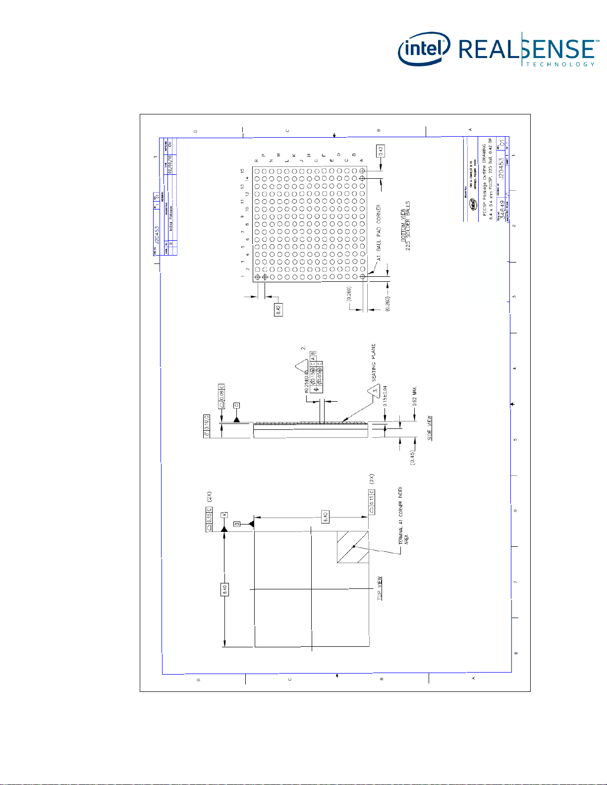
Table 3-4. Vision Processor D4 Package Mechanical Attributes
Pin
Boot Load
HW/FW
Package Technology
Package Type
FlipChip CSP (Chip Scale Package)
Interconnect
Ball Grid Array (BGA) Ball
Lead Free
Yes
Halogenated Flame Retardant Free
Yes
Package Configuration
Solder Ball Composition
SAC125Ni
Ball/Pin Count
225 solder balls
Grid Array Pattern
15 x 15
Package Dimensions
Nominal Package Size (mm)
6.40 x 6.40
Min Ball/Pin pitch (mm)
0.42
Weight ~1 gm
Page 27
Component Specification
337029-007 27
Figure 3-1. Vision Processor D4 Package Drawing
Page 28
Component Specification
28 337029-007
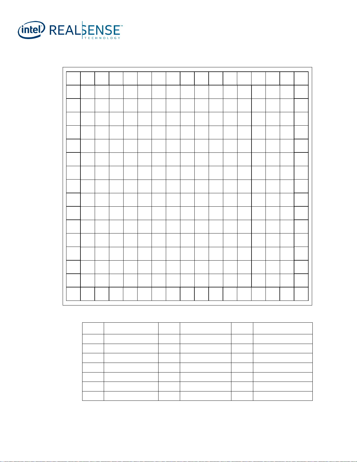
Figure 3-2. Vision Processor D4 Ball-out
A B C D E F G H J K L M N P R
15
VSS
Y_DATAN0
Y_REXT Y_SCL GPIO_0 GPIO_1 GPIO_5 GPIO_6
MODSTROB
TMS TRSTN SPI_WPN SPI_MISO
CW_CSR_RSTN
VSS
15
14
Y_CLKN Y_CLKP
Y_DATAP0
Y_RCLK Y_SDA
Y_RESETN
GPIO_2 GPIO_3
MODSIGN
TCLK TDO SPI_CLK SPI_MOSI
Z_RESETN
Z_VSYNC
14
13
Y_DATAN1 Y_DATAP1
VSS VSS
Y_PDOWN
Y_VSYNC GPIO_4 GPIO_7 LD_ERR
LD_ON_OUT_XX
TDI SPI_CS Z_SDA
Z_DATAP0
Z_RCLK
13
12
B_DATAN0
B_SCL B_SDA Y_AVDD VSS V SS
VDDPST18_LEFT
VSS VSS
VDDPST18_LEFT
VSS VSS Z_SCL Z_CLKP
Z_DATAN0
12
11
B_CLKN
B_DATAP0
B_REXT VSS VSS VSS V DD VDD V DD VSS VS S Z_AVDD
Z_PDOWN Z_DATAP1
Z_CLKN
11
10
B_DATAN1
B_CLKP
B_RESETN
B_AVDD VDD_PG VDD_PG V DD_PG VDD VDD VDD_PG VDD_PG ISP _SCL Z_REXT
M_DATAP1 Z_DATAN1
10
9
H_DATAN3 B_DATAP1 B_PDOW N
VSS V DD_PG VDD_PG VDD_PG VSS VSS VDD_PG VDD_PG VSS ISP_SDA M_CLKP
M_DATAN1
9
8
H_DATAN2 H_DATAP3
B_VSYNC V SS VSS VDD_PG VDD_PG VSS V SS VS S VSS V SS VSS
M_DATAP0
M_CLKN
8
7
H_CLKN
H_DATAP2
B_RCLK H_AVDD VSS VSS V SS VSS V SS V DD_PG VDD_PG M_AVDD
M_RESETN M_PDOWN M_D ATAN0
7
6
H_DATAN1
H_CLKP H_AVDD
REFPADCLKP REFPADCLKM
VSS VDD V DD VSS VDD_PG VDD_PG M_REXT
M_VSYNC
M_SDA M_RCLK
6
5
H_DATAN0 H_DATAP1
H_REXT VP USB_ID VDD VDD V DD VSS VSS VSS VSS VSS
A_DATAP1
M_SCL
5
4
H_SCL
H_DATAP0
USB_VDD330
VPTX0
USB_RESREF
USB_DVDD
VSS VSS
VDDPST18_RIGHT
VSS VSS A_AVDD A_REXT A_CLKP
A_DATAN1
4
3
USB_RXN H_SDA PRSTN USB_DP EGPIO_1 EGPIO_11 V DDTS VSSTS
VDDPST18_RIGHT
PMU_PWR_EN
VQPSQ VQPSM
A_PDOWN A_DATAP0
A_CLKN
3
2
USB_TXN USB_RXP DFU USB_DN EGPIO_9 EGPIO_13 VDDPLL VSSPLL EGPIO_5 EGPIO_12 EGPIO_3 EGPIO_4 A_SCL A_RCLK
A_DATAN0
2
1
VSS USB_TXP VBUS0 EGPIO_6 EGPIO_7 EGPIO_8 CLK_XIN
CLK_XOUT
EGPIO_10 EGPIO_2 EGPIO_0 A_VSYNC A_SDA
A_RESETN
VSS
1
A B C D E F G H J K L M N P R
Table 3-5. Vision Processor D4 Ball-out by Signal Name
Ball
Name
Ball
Name
Ball
Name
A01
H_AGND
B01
USB_TXP
C01
VBUS0
A02
USB_TXN
B02
USB_RXP
C02
DFU
A03
USB_RXN
B03
H_SDA
C03
PRSTN
A04
H_SCL
B04
H_DATAP0
C04
USB_VDD330
A05
H_DATAN0
B05
H_DATAP1
C05
H_REXT
A06
H_DATAN1
B06
H_CLKP
C06
H_AVDD
A07
H_CLKN
B07
H_DATAP2
C07
B_RCLK
Page 29

Component Specification
337029-007 29
Ball
Name
Ball
Name
Ball
Name
A08
H_DATAN2
B08
H_DATAP3
C08
B_VSYNC
A09
H_DATAN3
B09
B_DATAP1
C09
B_PDOWN
A10
B_DATAN1
B10
B_CLKP
C10
B_RESETN
A11
B_CLKN
B11
B_DATAP0
C11
B_REXT
A12
B_DATAN0
B12
B_SCL
C12
B_SDA
A13
Y_DATAN1
B13
Y_DATAP1
C13
Y_AGND
A14
Y_CLKN
B14
Y_CLKP
C14
Y_DATAP0
A15
Y_AGND
B15
Y_DATAN0
C15
Y_REXT
D01
EGPIO_6
E01
EGPIO_7
F01
EGPIO_8
D02
USB_DN
E02
EGPIO_9
F02
EGPIO_13
D03
USB_DP
E03
EGPIO_1
F03
EGPIO_11
D04
VPTX0
E04
USB_RESREF
F04
USB_DVDD
D05
VP
E05
USB_ID
F05
VDD
D06
REFPADCLKP
E06
REFPADCLKM
F06
VSS
D07
H_AVDD
E07
H_AGND
F07
VSS
D08
B_AGND
E08
VSS
F08
VDD_PG
D09
B_AGND
E09
VDD_PG
F09
VDD_PG
D10
B_AVDD
E10
VDD_PG
F10
VDD_PG
D11
VSS
E11
VSS
F11
VSS
D12
Y_AVDD
E12
VSS
F12
VSS
D13
VSS
E13
Y_PDOWN
F13
Y_VSYNC
D14
Y_RCLK
E14
Y_SDA
F14
Y_RESETN
D15
Y_SCL
E15
GPIO_0
F15
GPIO_1
G01
CLK_XIN
H01
CLK_XOUT
J01
EGPIO_10
G02
VDDPLL
H02
VSSPLL
J02
EGPIO_5
G03
VDDTS
H03
VSSTS
J03
VDDPST18_RIGHT
G04
VSS
H04
VSS
J04
VDDPST18_RIGHT
G05
VDD
H05
VDD
J05
VSS
G06
VDD
H06
VDD
J06
VSS
G07
VSS
H07
VSS
J07
VSS
G08
VDD_PG
H08
VSS
J08
VSS
G09
VDD_PG
H09
VSS
J09
VSS
G10
VDD_PG
H10
VDD
J10
VDD
G11
VDD
H11
VDD
J11
VDD
G12
VDDPST18_LEFT
H12
VSS
J12
VSS
Page 30

Component Specification
30 337029-007
Ball
Name
Ball
Name
Ball
Name
G13
GPIO_4
H13
GPIO_7
J13
LD_ERR
G14
GPIO_2
H14
GPIO_3
J14
MODSIGN
G15
GPIO_5
H15
GPIO_6
J15
MODSTROB
K01
EGPIO_2
L01
EGPIO_0
M01
A_VSYNC
K02
EGPIO_12
L02
EGPIO_3
M02
EGPIO_4
K03
PMU_PWR_EN
L03
VQPSQ
M03
VQPSM
K04
VSS
L04
VSS
M04
A_AVDD
K05
VSS
L05
VSS
M05
VSS
K06
VDD_PG
L06
VDD_PG
M06
M_REXT
K07
VDD_PG
L07
VDD_PG
M07
M_AVDD
K08
VSS
L08
VSS
M08
M_AGND
K09
VDD_PG
L09
VDD_PG
M09
M_AGND
K10
VDD_PG
L10
VDD_PG
M10
ISP_SCL
K11
VSS
L11
VSS
M11
Z_AVDD
K12
VDDPST18_LEFT
L12
VSS
M12
VSS
K13
LD_ON_OUT_XX
L13
TDI
M13
SPI_CS
K14
TCLK
L14
TDO
M14
SPI_CLK
K15
TMS
L15
TRSTN
M15
SPI_WPN
N01
A_SDA
P01
A_RESETN
R01
A_AGND
N02
A_SCL
P02
A_RCLK
R02
A_DATAN0
N03
A_PDOWN
P03
A_DATAP0
R03
A_CLKN
N04
A_REXT
P04
A_CLKP
R04
A_DATAN1
N05
A_AGND
P05
A_DATAP1
R05
M_SCL
N06
M_VSYNC
P06
M_SDA
R06
M_RCLK
N07
M_RESETN
P07
M_PDOWN
R07
M_DATAN0
N08
VSS
P08
M_DATAP0
R08
M_CLKN
N09
ISP_SDA
P09
M_CLKP
R09
M_DATAN1
N10
Z_REXT
P10
M_DATAP1
R10
Z_DATAN1
N11
Z_PDOWN
P11
Z_DATAP1
R11
Z_CLKN
N12
Z_SCL
P12
Z_CLKP
R12
Z_DATAN0
N13
Z_SDA
P13
Z_DATAP0
R13
Z_RCLK
N14
SPI_MOSI
P14
Z_RESETN
R14
Z_VSYNC
N15
SPI_MISO
P15
CW_CSR_RSTN
R15
Z_AGND
Page 31

Component Specification
337029-007 31
3.3.4 Vision Processor D4 Power Requirements
The Vision Processor D4 requires the following power supplies for operation.
Table 3-6. Vision Processor D4 Power Requirements
Voltage Ball Name
Min.
(V)
Nominal
(V)
Max.
(V)
Peak Current
(Icc)
VDD
0.85
0.9
0.95
0.4A
VDD_PG
0.85
0.9
0.95
1.6A
USB_DVDD
0.81
0.9
0.99
0.2A
VPTX0
0.81
0.9
0.99
0.2A
VP
0.81
0.9
0.99
0.2A
*AVDD
1.71
1.8
1.89
0.2A
VDDPLL
0.85
0.9
0.95
0.2A
VDDTS
1.71
1.8
1.89
0.2A
VDDPST18 (Left and
Right)
1.71
1.8
1.89
0.2A
USB_VDD330
3.13
3.3
3.46
0.2A
3.3.5 Vision Processor D4 Power Sequencing
The timing requirement for power sequencing is listed below and shown in the
following figure.
• Hold Vision Processor D4 in reset
• Ramp up power in the 3.3V
• Ramp up power in the 0.9V
• Ramp up power in the 1.8V
• Release Vision Processor D4 Reset
Table 3-7. Vision Processor D4 Power Sequencing Timing Parameters
Parameter
Value
Units
Label
0.9V stable to 3.3V stable
>=50
us
T1
PMU_PWR_EN to 0.9V Stable
>=50
us
T2
1.8V stable to 0.9V Stable
>=50
us
T3
PRSTN (D4 RESET) assertion to 1.8V stable
15
us
T4
Page 32

Component Specification
32 337029-007
Figure 3-3. Vision Processor D4 Power Sequencing
Note: Vision Processor D4 has no specific power down sequence requirement.
3.3.6 Vision Processor D4 Spec Code
The spec code is an identification mark printed on Vision Processor D4.
Table 3-8. Vision Processor D4 SPEC Code
Vision Processor D4
SPEC CODE
Production (Shipped in Tape and Reel)
SLLY5
Production (Shipped in Tray)
SLM6B
3.3.7 Vision Processor D4 Storage and Operating Conditions
Table 3-9. Vision Processor D4 Storage and Operating Conditions
Condition
Description
Min
Max
Unit
Storage (Still Air), Not
Operating
Temperature (Sustained,
Controlled)
(1)
0
40 oC
Page 33

Component Specification
337029-007 33
Temperature (Short
Exposure)
(2)
-40
70 oC
Humidity
Temperature/ RH: 40oC / 90%
Component Case
Temperature
(3)
Temperature
0
110 oC
NOTE:
(1) Controlled conditions should be used for long term storage of product.
(2) Short exposure represents temporary max limits acceptable for transportation conditions.
(3) Component case temperature limits must be met for all operating temperatures.
3.3.8 Vision Processor D4 Thermals
The thermal design should be such that Vision Processor D4 does not exceed
component case temperature limit. Care must also be taken to make sure that the
Vision Processor D4 heat is not transferred to other components of the imaging
system or stereo depth module. It will be best to thermally isolate Vision Processor D4
from the stereo depth module.
3.4 Clock
Vision Processor D4 requires a single 24 MHz clock oscillator. All clocks required by
stereo depth module are generated by Vision Processor D4.
3.5 Serial (SPI) Flash Memory
Vision Processor D4 requires 16Mbit Serial Flash Memory for its firmware storage. The
recommended part number is IS25WP016 (www.issi.com) or equivalent
3.6 Stereo Depth Module
The stereo depth module components are described in Table 3-10. The stereo depth
printed circuit board and components are encapsulated in a common metal stiffener.
Table 3-10. Stereo Depth Module
Component
Description
Left and Right Imagers
2 HD image sensors
Infrared (IR) Projector
Class 1 laser compliant (optional)
Color Sensor
1080p RGB image sensor (optional)
Depth Module Connector
50 pin connector plug
Privacy LED
Indicator when stereo module is streaming data (optional)
Stiffener
Reinforcement housing to keep imagers aligned
Label
Manufacture and product identifier information
Page 34

Component Specification
34 337029-007
Other Components
Laser Driver, EEPROM, Voltage Regulators, etc.
Figure 3-4. Stereo Depth Module (Intel® RealSense™ Depth Module D410)
Right
Imager
Left
Imager
IR
Projector
Camera
Connector
Module
Label
Figure 3-5. Stereo Depth Module (Intel® RealSense™ Depth Module D430)
Right Imager Left ImagerIR Projector
Camera
Connector
Module Label
Table 3-11. Stereo Depth Module SKU Properties
Stereo Module
Intel®
RealSense™
Depth Module
D400
Intel®
RealSense™
Depth Module
D410
Intel®
RealSense™
Depth Module
D415
Intel®
RealSense™
Depth Module
D420
Intel®
RealSense™
Depth Module
D430
Baseline
55mm
55mm
55mm
50mm
50mm
Left/Right
Imagers Type
Standard
Standard
Standard
Wide
Wide
Depth FOV HD
(degrees)
H:65±2 /
V:40±1 /
D:72±2
H:65±2 /
V:40±1 /
D:72±2
H:65±2 /
V:40±1 /
D:72±2
H:87±3 /
V:58±1 /
D:95±3
H:87±3 /
V:58±1 /
D:95±3
Depth FOV VGA
(degrees)
H:50±2 /
V:40±1 /
D:61±2
H:50±2 /
V:40±1 /
D:61±2
H:50±2 /
V:40±1 /
D:61±2
H:75±3 /
V:62±1 /
D:89±3
H:75±3 /
V:62±1 /
D:89±3
IR Projector
-
Standard
Standard
-
Wide
IR Projector FOV
-
H:67 / V:41 /
D:75
H:67 / V:41 /
D:75
-
H:90 / V:63 /
D:99
Color Sensor
-
-
OV2740
-
-
Color Camera
FOV
-
-
H:69±1/
V:42±1 /
D:77±1
-
-
Page 35

Component Specification
337029-007 35
Module
Dimensions
(mm)
X=74.7mm
Y=10mm
Z=4.7mm
X=74.7mm
Y=10mm
Z=4.7mm
X=83.7mm
Y=10mm
Z=4.7mm
X=70.7mm
Y=14mm
Z=10.53mm
X=70.7mm
Y=14mm
Z=10.53mm
NOTE:
• H – Horizontal FOV, V – Vertical FOV, D – Diagonal FOV, X – Length, Y – Breadth, Z –
Thickness
• Depth FOV specified at 2 meters
• Due to mechanical tolerances of +/-5%, Max and Min FOV values can vary from lens to
lens and module to module by ~ +/- 3 degrees.
3.6.1 Left and Right Imagers
The stereo depth module has two camera sensors referred here as imagers, they are
identical parts and are configured with identical settings. The imagers are labeled
“left” and “right” from the perspective of the camera module looking outward. The
stereo imager pairs are referred as Standard or Wide based on imager field of view.
Table 3-12. Standard Left and Right Imager Properties
Parameter
Camera Sensor Properties
Image Sensor
OmniVision OV2740
Active Pixels
1920 × 1080
Sensor Aspect Ratio
16:9
Format
10-bit RAW
F Number
f/2.0
Focal Length
1.88mm
Filter Type
IR Cut – D400, None – D410, D415, Camera D415
Focus
Fixed
Shutter Type
Rolling Shutter
Signal Interface
MIPI CSI-2, 2X Lanes
Horizontal Field of View
69.4o
Vertical Field of View
42.5o
Diagonal Field of View
77o
Distortion
<=1.5%
Table 3-13. Wide Left and Right Imager Properties
Parameter
Camera Sensor Properties
Image Sensor
OmniVision OV9282
Active Pixels
1280 X 800
Sensor Aspect Ratio
8:5
Page 36

Component Specification
36 337029-007
Parameter
Camera Sensor Properties
Format
10-bit RAW
F Number
f/2.0
Focal Length
1.93mm
Filter Type
IR Cut – D420, None – D430, D435/D435i
Focus
Fixed
Shutter Type
Global Shutter
Signal Interface
MIPI CSI-2, 2X Lanes
Horizontal Field of View
91.2o
Vertical Field of View
65.5o
Diagonal Field of View
100.6o
Distortion
<=1.5%
3.6.2 Infrared Projector
The infrared projector improves the ability of the stereo camera system to determine
depth by projecting a static infrared pattern on the scene to increase texture on low
texture scenes. The infrared projector meets class 1 laser safety under normal
operation. The power delivery and laser safety circuits are on the stereo depth
module. The infrared projector is referred as Standard or Wide based on field of
projection.
Table 3-14. Standard Infrared Projector Parameters
Parameter
Properties
Projector
Infrared
Pattern Type
Static
Illuminating Component
Vertical-cavity surface-emitting laser (VCSEL) + Optics
Laser Controller
PWM
Optical Power
360mW average, 440mW peak
Laser Wavelength
850nm ± 10 nm nominal @ 20°C
Laser Compliance
Class 1, IEC 60825-1:2007 Edition 2, IEC 60825-1:2014
Edition 3
Horizontal Field of Projection
64°±3°
Vertical Field of Projection
41°±3°
Diagonal Field of Projection
72°±3°
Table 3-15. Wide Infrared Projector Parameters
Parameter
Properties
Projector
Infrared
Page 37

Component Specification
337029-007 37
Parameter
Properties
Pattern Type
Static
Illuminating Component
Vertical-cavity surface-emitting laser (VCSEL) + optics
Laser Controller
PWM
Optical Power
360mW average, 4.25W peak
Laser Wavelength
850nm ± 10 nm nominal @ 20°C
Laser Compliance
Class 1, IEC 60825-1:2007 Edition 2, IEC 60825-1:2014
Edition 3
Horizontal Field of Projection
86°±3°
Vertical Field of Projection
57°±3°
Diagonal Field of Projection
94°±3°
3.6.3 Color Sensor
The color sensor on the stereo depth module in addition to color image provides
texture information. Usages for the texture information include overlay on a depth
image to create a color point cloud and overlay on a 3d model for reconstruction.
Table 3-16. Color Sensor Properties
Parameter
Camera Sensor Properties
Image Sensor
OmniVision OV2740
Color Image Signal Processor
Discrete
Active Pixels
1920 X 1080
Sensor Aspect Ratio
16:9
Format
10-bit RAW RGB
F Number
f/2.0
Focal Length
1.88mm
Filter Type
IR Cut Filter
Focus
Fixed
Shutter Type
Rolling Shutter
Signal Interface
MIPI CSI-2, 1 Lane
Horizontal Field of View
69.4o
Vertical Field of View
42.5o
Diagonal Field of View
77o
Distortion
<=1.5%
Page 38

Component Specification
38 337029-007
3.6.4 Depth Module Connector
The depth module connector provides signal and power interface to the stereo depth
module. The connector on stereo depth module is a 50-pin connector plug.
Table 3-17. Depth Module 50-pin Connector Plug Details
Parmeter
Description
Diagram
Number of Contacts
50
Product Name
NOVASTACK 35-P
Plug Assembly
Part Number
20708-050E
Manufacturer Website
www.i-pex.com
3.6.5 Stereo Depth Module Label
Table 3-18. Stereo Depth Module Product Labeling
For illustration purpose only, subject to
change
Dimension
Value
Unit
A
Label Width
17
mm
B
Label Height
6.9
mm
C
Scan Code Width
5
mm
D
Scan Code
Height
5
mm
Scan Code Format
XXXXXXXXXXXXOOOOOOXXXXXX-XXX
Table 3-19. Stereo Depth Module Label Fields
Group
Field
Description
Type
Company
Intel
Manufacturer
Static
Model Number
RealSenseTM Camera
4XX
Camera Model Number
Static
Product Assembly
Number
XXXXXX
Product Identifier Code
Static
-XXX
Manufacture Configuration
Code
Dynamic
OOOOOO
Product Material Code
Static
Serial Number
XXXXXXXXXXXX
Manufacture Unit Code
Dynamic
Page 39

Component Specification
337029-007 39
Note: Product Material Code (MM code) within the QR code on the label of the device will
read “000000”. The QR code MM code will be zero.
Table 3-20. Intel® RealSense™ Depth Module D400 Series Product Identifier Code and
Product Material Code
Production
Product Identifier Code-
Manufacture Configuration Code
Product Material Code
Depth Module D400
J32082-100
951934
Depth Module D410
J32106-100
951913
Depth Module D415
J32114-100
952000
Depth Module D420
J51355-100
956826
Depth Module D430
J42086-100
954010
3.6.6 Stiffener
The stiffener maintains the precise alignment of the camera sensors and assists in
subassembly rigidity. The stiffener consists of a bottom and a top plate. The stiffener
is of stainless steel grade AISI 304.
3.6.7 Temperature Sensor
The stereo depth module is equipped with a thermal sensor that is used for laser
safety control (IR Projector). The RealSense library provides access to the thermal
sensor but it is not intended to be used by applications outside of development
environments.
3.6.8 Other Stereo Depth Module Components
Table 3-21. Other Stereo Depth Module Components
Component
Description
Laser (IR
Projector) Driver
The depth module implements a laser driver which controls the infrared
laser within the infrared projector system.
Laser (IR
projector)
Thermal Control
The depth module implements a laser safety control circuit that adjusts
laser drive output. When laser power and depth streaming is enabled and if
stereo depth module temperature is >60°, laser power is halved. If
temperature is not lowered below temperature limit within a certain
interval, the laser is shut off.
EEPROM
The depth module implements flash memory for storing the calibration data.
Fork/Screw Mount
Secure placement and mounting to system/chassis/heat sink
Page 40

Component Specification
40 337029-007
Voltage
Regulators
The stereo depth module implements DC to DC voltage converters
3.6.9 Mechanical Dimensions
Table 3-22. Intel® RealSense™ Depth Module D400 Mechanical Dimensions
Dimension
Min
Nominal
Max
Unit
Width
74.5
74.7
74.9
mm
Height
9.8
10
10.2
mm
Depth
4.5
4.7
4.9
mm
Flatness Tolerance
-
0.2
-
mm
Weight
6.5
7.2
8
gr
Table 3-23. Intel® RealSense™ Depth Module D410 Mechanical Dimensions
Dimension
Min
Nominal
Max
Unit
Width
74.5
74.7
74.9
mm
Height
9.8
10
10.2
mm
Depth
4.5
4.7
4.9
mm
Flatness Tolerance
-
0.2
-
mm
Weight
7.3
8.1
8.9
gr
Table 3-24. Intel® RealSense™ Depth Module D415 Mechanical Dimensions
Dimension
Min
Nominal
Max
Unit
Width
89.5
89.7
89.9
mm
Height
9.8
10
10.2
mm
Depth
4.5
4.7
4.9
mm
Flatness Tolerance
TBD
mm
Weight
TBD
gr
Table 3-25. Intel® RealSense™ Depth Module D420 Mechanical Dimensions
Dimension
Min
Nominal
Max
Unit
Width
70.5
70.7
70.9
mm
Height
13.8
14
14.2
mm
Depth
10.33
10.53
10.73
mm
Flatness Tolerance
-
0.2
-
mm
Weight
TBD
gr
Page 41

Component Specification
337029-007 41
Table 3-26. Intel® RealSense™ Depth Module D430 Mechanical Dimensions
Dimension
Min
Nominal
Max
Unit
Width
70.5
70.7
70.9
mm
Height
13.8
14
14.2
mm
Depth
10.33
10.53
10.73
mm
Flatness Tolerance
-
0.2
-
mm
Weight
13
14.5
16
gr
3.6.10 Stereo Depth Module Power Sequence
Figure 3-6. Stereo Depth Module Power Sequence
3.3V
1.8V
3.6.11 Stereo Depth Module Storage and Operating Conditions
Table 3-27. Stereo Depth Module Storage and Operating Conditions
Condition
Description
Min
Max
Unit
Storage (Ambient), Not
Operating
Temperature (Sustained,
Controlled)
(1)
0
40 oC
Temperature (Short
Exposure)
(2)
-40
70 oC
Humidity
Temperature/ RH: 40oC / 90%
Case Temperature
(3)(4)(5)
Temperature
0
50 oC
NOTE:
(1) Controlled conditions should be used for long term storage of product.
(2) Short exposure represents temporary max limits acceptable for transportation conditions.
(3) Case temperature limits must be met for all operating temperatures.
(4) Case temperature is specified for the overall depth module
(5) Case temperature 0° minimum and lower temperatures is non-condensing
Page 42

Component Specification
42 337029-007
3.7 Intel
®
RealSense™ Vision Processor D4 Board
The Vision Processor D4 Board enables an easy and quick option for system
integrators to integrate Vision Processor D4 into a system.
Table 3-28. Vision Processor D4 Board
Type
Description
USB Peripheral
Type-C
Connects to Host USB 3.1 Gen 1 port through USB Type-C connector and
cable
Note: When connecting to host system, connect Type-C connection to
the camera prior to connecting device to host system port.
Table 3-29. Vision Processor D4 Board Components
Components
Description
Vision Processor D4
Stereo Depth Processing ASIC
16Mb Serial Flash
Vision Processor D4 firmware storage
24MHz Crystal
Clock source for Vision Processor D4
Realtek* ISP with external serial flash
Color image signal processor
Depth Module Receptacle
50 pin receptacle for connection to Stereo Depth
Module
USB Type-C
USB peripheral connector for connection to Host
USB 2.0/USB 3.1 Gen 1 port
External Sensor Sync Connector
Interface to external sensor interrupts/sync signals
Voltage Regulators
DC to DC converters powering Vision Processor D4
Board and stereo depth module.
Mounting holes
Vision Processor D4 Board secure mounting
Figure 3-7. Vision Processor D4 Board (USB Peripheral Type-C)
Depth Module
Receptacle
External Sensor
Sync Connector
USB Type-C
Connector
Vision Processor D4
Page 43

Component Specification
337029-007 43
3.7.1 Mechanical Dimensions
Table 3-30. Vision Processor D4 USB Type-C Board Mechanical Dimensions
Dimension
Min
Nominal
Max
Unit
Width
72.2
72.4
72.6
mm
Height
15.8
16
16.2
mm
Depth
3.74
3.94
4.14
mm
Weight
3.56
3.96
4.36
gr
3.7.2 Depth Module Receptacle
The Vision Processor D4 Board interface to stereo depth module is through 50 pin
receptacle on the board.
Table 3-31. Depth Module Receptacle Details
Parameter
Description
Diagram
Number of Contacts
50
Product Name
NOVASTACK* 35-P
Receptacle Assembly
Part Number
20709-050E
Manufacturer Website
www.i-pex.com
3.7.3 Flex and Rigid Interposer Interconnect
The high speed interposer at one end has the 50 pin depth module receptacle to
connect into 50 pin depth module plug on stereo depth module and at the other end
has the 50 pin depth module plug to connect into 50 pin depth module receptacle on
Vision Processor D4 Board. The high speed flex Interposer is custom developed and
procured by system integrator.
Page 44

Component Specification
44 337029-007
Figure 3-8. Flex Interposer (Illustration)
Figure 3-9. Rigid Interposer (Illustration)
Page 45

Component Specification
337029-007 45
Figure 3-10. Depth Module Receptacle and Plug Connector Pin Position
Table 3-32. Interposer Interconnect Signal Description
Position
ASIC Board/
Motherboard
Depth Module
Interconnect Description
1
RGB_RSTN_N
RGB_RSTN_N
RGB Sensor Reset
2
GND
GND
Ground
3
RGB_XCL
RGB_XCL
RGB Sensor Clock
4
RGB_MDP0
RGB_MDP0
RGB Sensor MIPI Data Lane 0 differential pair positive
5
GND
GND
Ground
6
RGB_MDN0
RGB_MDN0
RGB Sensor MIPI Data Lane 0 differential pair
negative
Page 46

Component Specification
46 337029-007
Position
ASIC Board/
Motherboard
Depth Module
Interconnect Description
7
RGB_FSYNC
RGB_FSYNC
RGB Sensor Sync
8
GND
GND
Ground
9
RGB_STROBE
RGB_STROBE
RGB Sensor Strobe
10
RGB_MCP
RGB_MCP
RGB Sensor MIPI Clock differential pair positive
11
RGB_SDA
RGB_SDA
RGB Sensor I2C Bus Data
12
RGB_MCN
RGB_MCN
RGB Sensor MIPI Clock differential pair negative
13
RGB_SCL
RGB_SCL
RGB Sensor I2C Bus Clock
14
GND
GND
Ground
15
GND
GND
Ground
16
MDP0_L
MDP0_L
Left Imager MIPI Data Lane 0 differential pair positive
17
VDD18V
VDD18V
1.8V Power
18
MDN0_L
MDN0_L
Left Imager MIPI Data Lane 0 differential pair
negative
19
VDD18V
VDD18V
1.8V Power
20
GND
GND
Ground
21
LED_PSY
LED_PSY
Privacy LED control signal
22
MCP_L
MCP_L
Left Imager MIPI Clock differential pair positive
23
DVSYNC
DVSYNC
VSYNC
24
MCN_L
MCN_L
Left Imager MIPI Clock differential pair negative
25
NC
NC
No Connect
26
GND
GND
Ground
27
XVCLK_L
XVCLK_L
Clock to Left Imager
28
MDP1_L
MDP1_L
Left Imager MIPI Data Lane 1 differential pair positive
29
GND
GND
Ground
30
MDN1_L
MDN1_L
Left Imager MIPI Data Lane 1 differential pair
negative
31
ST_RST_N
ST_RST_N
Reset signal to Left and Right Imager
32
GND
GND
Ground
33
FF_RSTn
FF_RSTn
Laser Error
34
MDP0_R
MDP0_R
Right Imager MIPI Data Lane 0 differential pair
positive
35
GND
GND
Ground
36
MDN0_R
MDN0_R
Right Imager MIPI Data Lane 0 differential pair
negative
37
XVCLK_R
XVCLK_R
Clock to Right Imager
38
GND
GND
Ground
Page 47

Component Specification
337029-007 47
Position
ASIC Board/
Motherboard
Depth Module
Interconnect Description
39
I2C_SCL
I2C_SCL
I2C Bus Clock
40
MCP_R
MCP_R
Right Imager MIPI Clock differential pair positive
41
I2C_SDA
I2C_SDA
I2C Bus Data
42
MCN_R
MCN_R
Right Imager MIPI Clock differential pair negative
43
LASER_PWM
LASER_PWM
IR Projector Control Signal
44
GND
GND
Ground
45
LASER_PWRDN
LASER_PWRDN
IR Projector Power Down
46
MDP1_R
MDP1_R
Right Imager MIPI Data Lane 1 differential pair
positive
47
LASER_PWM1
LASER_PWM1
IR Projector Control Signal
48
MDN1_R
MDN1_R
Right Imager MIPI Data Lane 1 differential pair
negative
49
FLAGB
FLAGB
IR Projector Fault Detect
50
GND
GND
Ground
51
GND
GND
Ground
52
VDD33V
VDD33V
3.3V power
Figure 3-11. Depth Module Connector Orientation and Pin Position
-
Vision Processor D4 Card
Stereo Depth Module
Pin Position 1
Pin Position 50
Pin Position 50
P/N 20709-050E
P/N 20708-050E
Pin Position 1
Table 3-33. Custom Flex Interposer Ordering Logistics
Vendor
Sales Contact
COCOM CONSUMER
ELECTRONICS LTD.
Janine Langdale
email: Janine.Langdale@cc-e.co.uk
(O) +44 (0) 1444 461620
Page 48

Component Specification
48 337029-007
(M) +44 (0) 7905 692131
3.7.4 External Sensor Sync Connector
The external sensor connector provides the interface for external sensors to
synchronize to depth output.
Table 3-34. External Sensor Connector Details
Parameter
Description
Diagram
Number of Contacts
9
Product Name
9 Positions Header,
Shrouded Connector
Part Number
SM09B-SRSS-
TB(LF)(SN)
Manufacturer Website
www.jst-mfg.com
Table 3-35. External Sensor Sync Connector Pin List
Pin
Signal
Function
Description
1
GPIO3
GVSYNC0
Not Defined
2
GPIO4
GVSYNC1
IR Projector Power Down signal
3
GPIO5
GVSYNC2
External IR Projector Fault Detect
4
GPIO6
GVSYNC3
External IR Projector
5
Z_VSYNC
VSYNC
Depth VSYNC
6
LASER_PWM0
LASER PWM0
Laser control signal
7
LASER_PWM1
LASER PWM1
Laser control signal
8
VDD33V
Power
3.3V
9
GND
Ground
Ground
3.7.5 USB Peripheral Connector – Type-C
USB Type-C connector consists of 24 signal pins designed in a symmetrical way. The
connector z height is as low as 3mm and enables enhanced user experience by
allowing the USB Type-C plug to be plugged into a receptacle either right side up or
upside down. Interoperability between USB Type-C and legacy USB is possible through
standard legacy cable assemblies defined in USB Type-C Cable and Connector
specification.
Page 49

Component Specification
337029-007 49
Figure 3-12. USB Type-C Receptacle Pin Map
Table 3-36. USB Peripheral Connector Pin List
Pin
Signal
Function
Description
A1
GND
Power Delivery
Ground
A2
TX1+
USB 3.1 Gen 1 Data
First SuperSpeed TX Differential Pair Positive
A3
TX1-
USB 3.1 Gen 1 Data
First SuperSpeed TX Differential Pair Negative
A4
VBUS
Power Delivery
5V
A5
CC1
Control
Configuration Channel 1
A6
D+
USB2.0 Data
USB 2.0 differential pair positive
A7
D-
USB2.0 Data
USB 2.0 differential pair negative
A8
SBU1
Sideband
Sideband Use Signal 1
A9
VBUS
Power Delivery
5V
A10
RX2-
USB 3.1 Gen 1 Data
Second SuperSpeed RX Differential Pair Negative
A11
RX2+
USB 3.1 Gen 1 Data
Second SuperSpeed RX Differential Pair Positive
A12
GND
Power Delivery
Ground
B1
GND
Power Delivery
Ground
B2
TX2+
USB 3.1 Gen 1 Data
Second SuperSpeed TX Differential Pair Positive
B3
TX2-
USB 3.1 Gen 1 Data
Second SuperSpeed TX Differential Pair Negative
B4
VBUS
Power Delivery
5V
B5
CC2
Control
Configuration Channel 2
B6
D+
USB 2.0 Data
USB 2.0 differential pair positive
B7
D-
USB 2.0 Data
USB 2.0 differential pair negative
B8
SBU2
Sideband
Sideband Use Signal 2
B9
VBUS
Power Delivery
5V
B10
RX1-
USB 3.1 Gen 1.0 Data
First SuperSpeed RX Differential Pair Negative
B11
RX1+
USB 3.1 Gen 1.0 Data
First SuperSpeed RX Differential Pair Positive
B12
GND
Power Delivery
Ground
Page 50

Component Specification
50 337029-007
Table 3-37. Custom USB Type C cable Assemblies Ordering Logistics
Vendor
Website
Newnex Technology Corp.
http://www.newnex.com/realsense-3d-camera-connectivity.php
3.7.6 Color Image Signal Processor (ISP)
The color sensor data is sent to discrete Image Signal Processor (ISP) on the Vision
processor D4 Board for image adjustments, image scaling and processing functions to
help compensate for inherent inaccuracy in lens and sensor in providing a better
image quality. The processed color image is sent to the Vision Processor D4.
Table 3-38. ISP Properties
Parameter
ISP Properties
ISP Part Number on Vision Processor D4 Board
RTS5845
1M-bit Serial Flash for ISP
Winbond* W25X10CL or equivalent
Interface To Vision Processor D4
MIPI CSI-2, 2X Lanes
Interface To RGB Sensor
MIPI CSI-2, 1X Lane
3.7.7 Vision Processor D4 Board Power Requirements
The Vision Processor D4 Board is powered through VBUS power of the USB connector.
The Vision Processor D4 Board in turn power sources the stereo depth module.
Table 3-39. Vision Processor D4 Board Power Requirements
Parameter
Min
Nom
Max
Unit
VCC
Supply Voltage
4.75
5V
5.25V
V
ICC
Supply Current
700
mA
Supply Voltage Ramp Rate
0.5 5
ms
3.7.8 Vision Processor D4 Board Thermals
The Vision Processor D4 Board should be screw mounted on to a heat sink or a heat
dissipating structure element using screw forks on Board. Thermal conductive tape
(electrically non-conductive) should cover the entire back side area (non-component
side) of the ASIC Board for thermal transfer onto heat sink or heat dissipating
structure element.
Page 51

Component Specification
337029-007 51
3.7.9 Vision Processor D4 Board Storage and Operating
Conditions
Table 3-40. Vision Processor D4 Board Storage and Operating Conditions
Condition
Description
Min
Max
Unit
Storage (Still Air), Not Operating
Temperature
(Sustained,
Controlled)
(1)
0
40 oC
Temperature
(Short
Exposure)
(2)
-40
70 oC
Humidity
Temperature/ RH: 40oC / 90%
Case Temperature
(3)(4)(5)
Temperature
0
50 oC
NOTE:
(1) Controlled conditions should be used for long term storage of product.
(2) Short exposure represents temporary max limits acceptable for transportation conditions.
(3) Case temperature limits must be met for all operating temperatures.
(4) Case temperature is specified for the overall Vision Processor D4 Board
(5) Case temperature 0° minimum and lower temperatures is non-condensing
3.7.10 Intel
®
RealSense™ Vision Processor D4 Board Product
Identifier and Material Code
Table 3-41. Vision Processor D4 Board Product Identifier and Material Code
Production
Product Identifier
Code-Manufacture
Configuration Code
Product Material Code
Vision Processor D4 Board
J32139-120
952019
3.8 Intel
®
RealSense™ Depth Camera D400 Series
Figure 3-13. Intel® RealSenseTM Depth Camera D415
Page 52

Component Specification
52 337029-007
Figure 3-14. Intel® RealSense™ Depth Camera D435/D435i
Table 3-42. Depth Camera SKU properties
D400 series Depth
Cameras
Intel® RealSense™
Depth Camera
D415
Intel® RealSense™
Depth Camera
D435
Intel® RealSense™
Depth Camera
D435i
Depth module
Intel® RealSense™
Depth module D415
Intel® RealSense™
Depth module D430
Intel® RealSense™
Depth module D430
Baseline
55mm
50mm
50mm
Left/Right Imagers
Type
Standard
Wide
Wide
Depth FOV HD
(degrees)
H:65±2 / V:40±1 /
D:72±2
H:87±3 / V:58±1 /
D:95±3
H:87±3 / V:58±1 /
D:95±3
Depth FOV VGA
(degrees)
H:50±2 / V:40±1 /
D:61±2
H:75±3 / V:62±1 /
D:89±3
H:75±3 / V:62±1 /
D:89±3
IR Projector
Standard
Wide
Wide
IR Projector FOV
H:67 / V:41 / D:75
H:90 / V:63 / D:99
H:90 / V:63 / D:99
Color Sensor
OV2740
OV2740
OV2740
Color Camera FOV
H:69±1 /V:42±1
/D:77±1
H:69±1 /V:42±1
/D:77±1
H:69±1 /V:42±1
/D:77±1
IMU
NA
NA
6DoF
NOTE: H – Horizontal FOV, V – Vertical FOV, D – Diagonal FOV, X – Length, Y – Breadth, Z –
Thickness
3.8.1 Depth Camera D400 Series Mechanical Dimensions
Table 3-43. Intel® RealSense™ Depth Camera D415 Mechanical Dimensions
Dimension
Min
Nominal
Max
Unit
Width
98.85
99
99.15
mm
Height
22.85
23
23.15
mm
Depth
19.85
20
20.15
mm
Page 53

Component Specification
337029-007 53
Weight
68.4
72
75.6
gr
Flatness Tolerance
-
0.15
-
mm
Table 3-44. Intel® RealSense™ Depth Camera D435, D435i Mechanical Dimensions
Dimension
Min
Nominal
Max
Unit
Width
89.85
90
90.15
mm
Height
24.85
25
25.15
mm
Depth
24.85
25
25.15
mm
Weight
68.4
72
75.6
gr
Flatness Tolerance
-
0.15
-
mm
3.8.2 Depth Camera D400 Series Thermals
Table 3-45. Max Skin Temperature
D400-Series Depth
Cameras
Max Skin Temperature
(25 degree C Ambient in Open Environment)
D415
44 oC
D435
44 oC
D435i
44 oC
3.8.3 Depth Camera D400 Series Storage and Operating
Conditions
Table 3-46. Depth Camera D400 Series Storage and Operating Conditions
Condition
Description
Min
Max
Unit
Storage (Still Air), Not
Operating
Temperature (Sustained,
Controlled)
(1)
0
40 oC
Temperature (Short
Exposure)
(2)
-40
70 oC
Humidity
Temperature/ RH: 40oC / 90%
Operating (Still Air)
Temperature
0
35 oC
NOTE:
Page 54

Component Specification
54 337029-007
(1) Controlled conditions should be used for long term storage of product.
(2) Short exposure represents temporary max limits acceptable for transportation conditions.
3.8.4 Depth Camera D400 Series Product Identifier and Material
Code
Table 3-47. Depth Camera D400 Series Product Identifier and Material Code
Production
Product Identifier Code-
Manufacture Configuration
Code
Product Material
Code
Depth Camera D415
J72476-100
961443
Depth Camera D415 (Multi Pack)
J72476-100
962304
Depth Camera D435
J72479-100
961448
Depth Camera D435 (Multi Pack)
J72479-100
962305
Depth Camera D435i
K38179-100
999AFR
Depth Camera D435i (Multi Pack)
K38179-100
999AXG
3.8.5 Camera Lens Cleaning Procedure
1. Do not use any chemical or water on the camera lens
2. Remove dust and dirt as much as possible from the lens with a lens blower
brush.
3. Wipe with soft cloth or eyeglass lens wiper.
§§
Page 55

Functional Specification
337029-007 55
4 Functional Specification
4.1 Vendor Identification (VID) and Device
Identification (DID)
Table 4-1. Vendor ID and Device ID Table
Depth Module/Depth Camera
Vendor ID
Device ID
Intel® RealSense™ Depth Module D400
8086
0x0AD1
Intel® RealSense™ Depth Module D410
8086
0x0AD2
Intel® RealSense™ Depth Module D415
8086
0x0AD3
Intel® RealSense™ Depth Camera D415
8086
0x0AD3
Intel® RealSense™ Depth Module D420
8086
0x0AF6
Intel® RealSense™ Depth Module D430
8086
0x0AD4
Intel® RealSense™ Depth Camera D435
8086
0x0B07
Intel® RealSense™ Depth Camera D435i
8086
0x0B3A
4.2 Vision Processor D4 Data Streams
Intel® RealSense™ Vision Processor D4 Depth imaging system provides high quality
depth data to a host system. The depth data is generated with stereo vision
technology that is optionally assisted by an infrared projector. The imaging system
has the ability to syncronize with color stream.
Table 4-2. Image Formats (USB 3.1 Gen1)
Format
Resolution
Frame Rate
(FPS)
Comment
Z [16 bits]
1280x720
6,15,30
Depth
848X480
6,15,30,60,90
640x480
6,15,30,60,90
640x360
6,15,30,60,90
480x270
6,15,30,60,90
424x240
6,15,30,60,90
Y8 [8 bits]
1280x720
6,15,30
Luminance
Left and Right Imager
848X480
6,15,30,60,90
Page 56

Functional Specification
56 337029-007
Format
Resolution
Frame Rate
(FPS)
Comment
640x480
6,15,30,60,90
640x360
6,15,30,60,90
480x270
6,15,30,60,90
424x240
6,15,30,60,90
UYVY [16 bits]
1280x720
6,15,30
Color Stream from Left Imager
(D400, D410 & D415)
848X480
6,15,30,60,90
640x480
6,15,30,60,90
640x360
6,15,30,60,90
480x270
6,15,30,60,90
424x240
6,15,30,60,90
YUY2 [16 bits]
1920x1080
6,15,30
Color Stream from RGB camera
(Camera D415 & D435/D435i)
1280x720
6,15,30
960x540
6,15,30,60
848x480
6,15,30,60
640x480
6,15,30,60
640x360
6,15,30,60
424x240
6,15,30,60
320x240
6,30,60
320x180
6,30,60
Calibration [24 bits]
1920x1080
15,25
D400/D410/D415
1280x800
15,25
D420/D430/D435/D435i
NOTE:
Depth and Color are mapped as separated interfaces. Each one of the interfaces is working
independent with the other interface (Virtual channel in MIPI and End Point in USB).
To ensure USB 3.1 support, connect D400 series USB connector first prior to connecting
depth device to host system port.
Table 4-3. Image Formats (USB 2.0)
Format
Resolution
Frame Rate
Comment
Z [16 bits]
1280x720
6
Depth
640x480
6,15,30
480x270
6,15,30,60
Y8 [8 bits]
1280x720
6
Luminance
Left and Right Imager
640x480
6,15,30
480x270
6,15,30,60
Page 57

Functional Specification
337029-007 57
Format
Resolution
Frame Rate
Comment
UYVY [16 bits]
1280x720
6
Color Stream from Left Imager
(D410 & D415)
640x480
6,15,30
480x270
6,15,30,60
YUY2 [16 bits]
1280x720
6
Color Stream from RGB camera
(Camera D415 & D435/D435i)
640x480
6,15,30
424x240
6,15,30,60
NOTE:
Depth and Color are mapped as separated interfaces. Each one of the interfaces is working
independent with the other interface (Virtual channel in MIPI and End Point in USB).
Table 4-4. Simultaneous Image Streams (USB 3.1 Gen1 & USB2.0)
Depth
Imager
Color
(Left
Imager)
D400/D410
Color
(RGB
Camera)
D415/D435/D435i
IMU
D435i
Comment
Z16
Y8
Gyro &
Accelerometer
Z16 UYVY
Gyro &
Accelerometer
Z16
Y8 YUV2
Gyro &
Accelerometer
Z16
YUV2
Gyro &
Accelerometer
NOTE:
1. RGB to depth hardware sync is only supported with the same frame rate for all streams.
2. For Depth and RGB camera simultaneous streaming, it is recommended to have color
resolution to be the same or higher than depth resolution.
3. USB 3.1 Gen1 supports all resolution/frame rate combinations in a typical dedicated USB port
configuration. On a USB hub with other devices (e.g. other RealSense cameras),
considerations regarding bandwidth requirements have to be taken. To ensure USB 3.1
support, connect D400 series USB connector first prior to connecting depth device to host
system port.
4. USB 2.0 supports a subset of the resolution/frame rate combinations given the bandwidth
requirements.
▪ Max. Depth Resolution Simultaneous Stream Configuration with Depth at 640X480,
15 FPS, Left Imager at 640X480, 15 FPS and RGB Camera at 640X480, 30 FPS.
▪ Max. Depth Frame Rate Simultaneous Stream Configuration with Depth at 480X270,
60 FPS, Left Imager at 480X270, 60 FPS and RGB Camera at 424x240, 30 FPS
Page 58

Functional Specification
58 337029-007
4.3 Depth Field of View (FOV)
The depth field of view is the common overlap of the individual left and right Imager
field of view for which Vision Processor D4 provides depth data
Table 4-5. Depth Field of View
Format
D400/D410/D415
D420/D430/D435/D435i
Horizontal FOV (VGA 4:3)
48
74
Vertical FOV (VGA 4:3)
40
62
Diagonal FOV (4:3)
60
88
Horizontal FOV (HD 16:9)
64
86
Vertical FOV (HD 16:9)
41
57
Diagonal FOV (HD 16:9)
72
94
NOTE:
• Due to mechanical tolerances of +/-5%, Max and Min FOV values can vary from lens to
lens and module to module by ~ +/- 3 degrees.
• The Depth FOV specified is at 2 meters distance.
4.4 Depth Field of View at Distance (Z)
Depth Field of View (Depth FOV) at any distance (Z) can be calculated using the
equation
Depth FOV = Depth Field of View
HFOV = Horizontal Field of View of Left Imager on Depth Module
B = Baseline
Z = Distance of Scene from Depth Module
Page 59

Functional Specification
337029-007 59
Figure 4-1. Depth Field of View to Depth Map illustration
NOTES:
• As the scene distance from the depth module increases, the invalid depth band decreases
in the overall depth image. Overall depth image is invalid depth band plus valid depth
map.
4.5 Invalid Depth Band
The depth data generated with stereo vision uses the left imager as the reference for
stereo matching resulting in a non-overlap region in the field of view of left and right
imagers where we will not have depth data at the left edge of the frame. Closer
scenes result in a wider invalid depth band than scenes at larger distances.
Page 60

Functional Specification
60 337029-007
Figure 4-2. Left Invalid Depth Band
The width of the invalid depth band can be calculated using the following equations:
In terms of horizontal FOV
In terms of focal length
B= Baseline
Z= Distance of Scene from Depth Module
F= Focal length
HFOV= Horizontal Field of View of Left Imager on Depth Module
HRES= Horizontal Resolution
The equations stand valid for a base configuration of camera settings. Default camera
configuration in firmware may have settings optimized for depth performance that
may impact the actual width of invalid depth band when compared to the calculated
width of the invalid depth band from equations.
Page 61

Functional Specification
337029-007 61
4.6 Minimum-Z Depth
The Minimum-Z Depth is the minimum distance from depth camera to scene for which
Vision Processor D4 provides depth data.
Table 4-6. Minimum-Z Depth
Resolution
D400/D410/D415
D420/D430
Min-Z (mm)
Min-Z (mm)
1280x720
450
280
848X480
310
195
640x480
310
175
640x360
240
150
480x270
180
120
424x240
160
105
4.7 Depth Quality Specification
There are a set of standard metrics based on accuracy, data validity, and temporal
stability are used to quantify depth quality.
Although the module is designed for a certain depth FOV, the measurements are
taken within 80% of this FOV, defined as region of interest (ROI). This ROI will best
align with intended usage area and the optical parameters qualification field.
Table 4-7: Depth Quality Metric
METRIC
DEFINITION
(1)
Depth Accuracy
Measure the difference for valid pixels relative to a ground truth surface.
Fill Rate
Percentage of pixels that have a valid depth value.
Depth Standard Deviation
Measures the total spatial noise for each valid pixel relative to a best fit plane.
Pixel Temporal Noise
Measures the total temporal noise for each valid pixel relative to a best fit plane.
NOTES:
(1) Each measurement is taken from a predefined region of interest (ROI) which is within 80% of the depth
field of view (FOV).
Page 62

Functional Specification
62 337029-007
Table 4-8: Depth Quality Metric Illustration
DEPTH ACCURACY AND DEPTH RMS ERROR
FILL RATE
Table 4-9. Depth Quality Specification
Metric
D400/D410/D415
(up to 2 Meters and 80%
FOV)
D420/D430/D435/D435i
(up to 2 Meters and 80%
FOV)
Z-accuracy (or absolute error)
≤ 2%
≤ 2%
Fill rate
≥ 99%
≥ 99%
RMS Error (or Spatial Noise)
≤ 2%
≤ 2%
Temporal Noise (Pixel)
≤ 1%
≤ 1%
NOTES:
1) The Depth Quality spec applies to depth modules that have been completely
integrated in overall system and has successfully completed the OEM calibration
process.
2) For Depth Quality metric definitions and test methodology, refer to white paper
“Intel® RealSense™ Camera Depth Testing Methodology”
3) Laser Power: 150mW, Exposure: Auto Exposure
Page 63

Functional Specification
337029-007 63
4.8 Measured Power
Table 4-10. Power- Ubuntu 16.04
Model
Idle (W)
Normal Power (W)
Typical Usage
Configuration
Maximum Power (W)
Worst Case
Configuration
D400
0.04
1.44
1.44
D410
0.05
1.71
2.21
D420
0.04
1.12
D430
0.04
2.68
Table 4-11. Power – Windows 10 (RS4)
Model
Idle (W)
Normal Power (W)
Typical Usage
Configuration
Maximum Power (W)
Worst Case
Configuration
D400
0.04
1.44
1.44
D410
0.04
1.84
2.51
D420
0.04
1.08
D430
0.04
2.85
NOTES:
1) Power Configuration:
(C) – Color Resolution
Model
Configuration
Resolution
Frame Rate
Laser (IR)
Power Setting
Comments
D400
Typical
1280X720
30FPS
0mW
Worst Case
1280X720
30FPS
0mW
D410
Typical
1280X720
30FPS
150mW
Worst Case
1280X720
30FPS
330mW
D415
Typical
1280X720/
1280X720 (C)
30FPS
150mW
Worst Case
1280X720/
1920X1080 (C)
30FPS
330mW
D420
Typical
848X480
30FPS
0mW
Worst Case
1280X720
30FPS
0mW
D430
Typical
848X480
30FPS
150mW
Worst Case
1280X720
30FPS
330mW
D435/D435i
Typical
848X480/
1280X720 (C)
30FPS
150mW
Page 64

Functional Specification
64 337029-007
Worst Case
1280X720/
1920x1080 (C)
30FPS
330mW
4.9 Depth Start Point (Ground Zero Reference)
The depth start point or the ground zero reference can be described as the starting
point or plane where depth = 0. For depth modules (D400, D410 & D415), this point
is referenced from front of lens or from backside of module. For depth cameras (D415
and D435/D435i), this point is referenced from front of camera cover glass
Figure 4-3. Depth Module Depth Start Point Reference
Depth Start
Point
Front of Lens
Depth (Z)
Z”
D410 (Depth Module Side View)
Scene
Back of
Module
Z’
Table 4-12. Depth Module Depth Start Point
Depth Module
Front of Lens (Z’)
Back of Module (Z”)
D400/D410/D415
-0.1mm
4.3mm
D420/D430
-3.2mm
7.5mm
NOTES:
If depth measurement reference is front of lens, then |Z’| should be added to measured
value to determine Ground Truth. If depth measurement reference is back of module, then
|Z”| should be subtracted to determine Ground Truth.
Page 65

Functional Specification
337029-007 65
Figure 4-4. Depth Camera Depth Start Point Reference
Depth Start
Point
Front Cover
Glass
Depth (Z)
Z’
D435 (Depth Camera Side View)
Scene
Table 4-13. Depth Cameras Depth Start Point
Depth Camera
Camera Front Glass (Z’)
D415
-1.1mm
D435/D435i
-4.2mm
NOTES:
If depth measurement reference is front cover glass, then |Z’| should be added to measured
value to determine Ground Truth.
Page 66

Functional Specification
66 337029-007
4.9.1 Depth Origin X-Y Coordinates
The depth origin X-Y coordinates is the X-Y center of left imager.
Figure 4-5. Depth Module X-Y Depth Origin Reference
Table 4-14. Depth Module X-Y Depth Origin Coordinates
Depth Module
Left Alignment hole1 to Left imager Center
D400
8mm
D410
8mm
D415
8mm
D420
8mm
D430
8mm
NOTES:
1. Left alignment hole on bottom stiffener of depth module
2. Left alignment hole and left imager center is on depth module centerline.
Page 67

Functional Specification
337029-007 67
Figure 4-6. Depth Camera X-Y Depth Origin Reference
Table 4-15. Depth Camera X-Y Depth Origin Coordinates
Depth Camera
From Centerline of ¼-201 To Left Imager
D415
20mm
D435/D435i
17.5mm
NOTES:
1. Center of tripod mounting hole (1/4-20)
4.10 Depth Camera Functions
D4 exposes the following Depth image settings.
Table 4-16. Depth Camera Controls
Control
Description
Min
Max
Manual Exposure
(1)
(ms)
Control sensor exposure period
(400/410)
1
166
Manual Exposure
(1)
(ms)
Control sensor exposure period (430)
1
166
Manual gain
(1)
(Gain 1.0 = 16)
Control sensor digital gain.
16
248
Laser Power (on/off)
(On = 1)
Power to IR Projector
0
1
Manual Laser Power (mW)
Laser Power setting (30mW steps)
0
360
Page 68

Functional Specification
68 337029-007
Control
Description
Min
Max
Auto Exposure Mode
(Enable = 1)
Auto Exposure Mode. When Auto
Exposure is enabled, Exposure and
Gain are set based on the environment
condition
0
1
Auto Exposure ROI
Perform Auto Exposure on a selected
ROI
T-0
L-0
B-1
R-1
T-719
L-1279
B-720
R-1280
Preset
Set Controls parameters based on
Camera Usage
Meta Data Control
Enable/Disable Metadata
0
1
NOTES:
(1) – Not supported in Auto Exposure Mode
T - Top, L – Left, B - Bottom, R – Right
4.11 Color Camera Functions
Table 4-17. RGB Exposed Controls
Control
Description
Min
Max
Auto-Exposure Mode
Automatically sets the exposure
time and gain for the frame.
0x1
0x8
Auto Exposure ROI
Perform Auto Exposure on a
selected ROI
T-0
L-0
B-1
R-1
T-1079
L-1919
B-1080
R1920
Manual Exposure Time
Sets the absolute exposure time
when auto-exposure is disabled.
41
10000
Brightness
Sets the amount of brightness
applied when auto-exposure is
enabled.
-64
64
Contrast
Sets the amount of contrast based
on the brightness of the scene.
0
100
Gain
Sets the amount of gain applied to
the frame if auto-exposure is
disabled.
0
128
Hue
Sets the amount of hue adjustment
applied to the frame.
-180
180
Saturation
Sets the amount of saturation
adjustment applied to the frame.
0
100
Page 69

Functional Specification
337029-007 69
Control
Description
Min
Max
Sharpness
Sets the amount of sharpening
adjustment applied to the frame.
0
100
Gamma
Sets amount of gamma correction
applied to the frame.
100
500
White Balance
Temperature Control
Sets the white balance when AWB is
disabled.
2800
6500
White Balance
Temperature Auto
(AWB)
Enables or disables the AWB
algorithm.
0
1
Power Line Frequency
Specified based on the local power
line frequency for flicker avoidance.
0
3
Backlight
Compensation
Sets a weighting amount based on
brightness to the frame.
0
1
Low Light Comp
Low Light Compensation
0
1
NOTES:
T - Top, L – Left, B - Bottom, R – Right
4.12 IMU Specifications
Table 4-18. IMU Specifications
Camera
Parameter
Properties
Intel® RealSense™
Depth Camera
D435i (D435 +
BMI055)
Degrees of Freedom
6
Acceleration Range
±4g
Accelerometer Sample Rate1
62.5, 250 (Hz)
Gyroscope Range
±1000 deg/s
Gyroscope Sample Rate2
200, 400 (Hz)
Sample Timestamp Accuracy
50 usec
NOTES:
1. The sample rate may differ from the absolute specified sample rate by ±5%.
It is advised to rely on the sample timestamp.
2. The sample rate may differ from the absolute specified sample rate by ±0.3%.
§§
Page 70

Firmware
70 337029-007
5 Firmware
The firmware contains the operation instructions. Upon runtime, Vision Processor D4
loads the firmware and programs the component registers. If the Vision Processor D4
is configured for update or recovery, the unlocked R/W region of the firmware can be
changed.
5.1 Update
During a firmware update, the firmware utility will issue a device firmware update
command to the Vision Processor D4. The Vision Processor D4 will then reset into
firmware update mode. The firmware utility uses a single binary file to maintain the
firmware image. The firmware utility compares the firmware version installed on the
camera to the firmware version file to be updated. Based on the comparison, the
firmware utility will downgrade, upgrade, or skip if the versions match.
5.1.1 Update Limits
The firmware update engine does not allow infinite update cycles between older and
current versions of firmware. The engine will establish a baseline version of firmware
based on the latest firmware version installed. The engine will allow a return to a
previous version or baseline version of firmware up to 20 times. After the 20th
update, the engine will only allow an update to a firmware revision higher than the
baseline version.
5.2 Recovery
A read only boot sector is built into firmware which enables basic operation regardless
of the integrity of the operation instructions region. This ensures the imaging system
can function in the case of firmware not be written properly. When a firmware
recovery is required, the firmware utility will communicate with the recovery driver to
set the DFU pin low and reset the imaging system in recovery mode.
Firmware Recovery can also be externally triggered by having controllable interrupt
connected to the Vision Processor D4 DFU (Device Firmware Update) pin.
The firmware recovery sequence will be triggered by the firmware client utility. This
client utility will communicate through ACPI _DSM to trigger the controllable interrupt
(GPIO) at the appropriate times. The firmware recovery requires an ACPI _DSM
interface to control the interrupt GPIO in configuring to firmware recovery state. The
_DSM methods and BIOS use the Write to GPIO functions to set the controllable
interrupt.
§ §
Page 71

Software
337029-007 71
6 Software
6.1 Intel
®
RealSense™ Software Development Kit 2.0
Intel® RealSense™ SDK 2.0 is a cross-platform library for working with Intel®
RealSense™ D400 Series. It is open source and available on
https://github.com/IntelRealSense/librealsense
The SDK at a minimum includes:
• Intel® RealSense™ Viewer - This application can be used view, record and
playback depth streams, set camera configurations and other controls.
• Depth Quality Tool - This application can be used to test depth quality,
including: distance to plane accuracy, Z accuracy, standard deviation of the Z
accuracy and fill rate.
• Debug Tools - These command line tools gather data and generate logs to
assist in debug of camera.
• Code Examples - Examples to demonstrate the use of SDK to include D400
Series camera code snippets into applications.
• Wrappers -Software wrappers supporting common programming languages
and environments such as ROS, Python, Matlab, node.js, LabVIEW, OpenCV,
PCL, .NET and more
§§
Page 72

System Integration
72 337029-007
7 System Integration
The small size of the stereo depth module and the separate placement of Vision
Processor D4 provides system integrators flexibility to design into a wide range of
products. Because the camera uses stereo vision technology, it is crucial that the
stereo depth module does not flex throughout its service life. This creates unique
mechanical and thermal implementation guidance. This section explains how to
correctly integrate D4 depth camera into a system
7.1 System Level Block Diagram
Figure 7-1. System Block Diagram
7.2 Vision Processor D4 System Integration
There are two options to integrate Vision Processor D4 into a system, either by
integration of Vision Processor D4 Board or having the Vision Processor D4 and
support components directly on the host processor motherboard. Vision Processor D4
Board simplifies system design and integration of the D4 depth camera system and
Vision Processor D4 on Motherboard allows for a space optimized implementation of
the D4 depth camera system.
7.2.1 Vision Processor D4 Board
The Vision Processor D4 Board has a standard USB Type-C connector and requires an
appropriate USB Type-C cable to connect to a standard USB 2.0/USB 3.1 Gen 1
external port.
Page 73

System Integration
337029-007 73
Figure 7-2. Intel® RealSense™ Vision Processor D4 Board
USB3 Type-C
Connector
7.2.2 Vision Processor D4 on Motherboard
In the Vision Processor D4 on Motherboard option, Vision Processor D4 and support
components are directly placed on the host processor motherboard. The depth module
receptacle is on the host processor motherboard for connection to the stereo depth
module.
Figure 7-3. Vision Processor D4 on Motherboard (Illustration)
Stereo Depth Module
Host Processor SOC
Motherboard
Flex Interposer
D4
7.2.2.1 Firmware Update
SPI flash chip assembled onto the motherboard requires a bootable firmware image
for Vision Processor D4 to boot or to run the firmware update utility provided by Intel.
There are two options program flash with firmware image or to recover a corrupt
firmware image.
Page 74

System Integration
74 337029-007
1. Pre-program SPI flash chip with firmware before assembly on to motherboard
or replace corrupt image with a good image SPI flash chip. The blank SPI flash
chip can pre-programmed using a compatible adapter (i.e. PA8QFN8D) and
supporting flash programmer.
2. A header or test points is connected in parallel to the SPI flash chip, then
programmed directly with an SPI flash programmer. Vision Processor D4 SPI
interface is put in high Z state by strapping EPGPIO4 pin to Ground when
programmed directly with an SPI flash programmer.
7.3 D4 Camera System Power Delivery
D4 camera system MUST keep stereo depth module and the Vision Processor D4 on
the same power rails. The stereo depth module holds a safety region in EEPROM that
is configured by firmware protected region. Keeping all components on the same rail
prevents malicious software reset of the stereo depth module without causing a reset
to the ASIC. By this protection we make sure that all the safety logic is kept locked as
long as the device is active. Ensure power delivery implementation recommendation in
Chapter 12 are followed in the design of D4 camera system.
Figure 7-4. D4 Camera System Power Scheme
Vision
Processor
D4
3.3V
1.8V
VDD
VBUS0 V 330
*AVDD
VPTX0VP DVDD
VDDPG
VDDPLL
VDDTS VDDPST
PMU_EN
FET
ISP
3.3V
1.8V
3.3V
1.8V
Stereo
Depth
Connector
0.9V
Page 75

System Integration
337029-007 75
7.4 Vision Processor D4 Board for Integrated
Peripheral
In design of custom host processor motherboard with custom Vision Processor D4
Board for embedded applications, a low mechanical profile 10 pin USB 3.1 Gen 1
receptacle can be implemented on motherboard and Vision Processor D4 Board.
7.4.1 USB 3.1 Gen 1 Receptacle
Table 7-1. USB 3.1 Gen 1 Receptacle Characteristics
PROPERTY
DESCRIPTION
DIAGRAM
Shell Finish
Tin (Sn)
Lock
Yes
Ground Bar
Yes
Alignment Boss
No
Part Number
IPEX 20347-310E-12R
Table 7-2. USB 3.1 Gen 1 Receptacle Pin Out
POSITION
NAME
TYPE
DESCRIPTION
1
GND
-
Ground
2
USB3_SS
TX-
OUT
USB 3.1 Gen 1 Transmitter Negative
3
USB3_SS
TX+
OUT
USB 3.1 Gen 1 Transmitter Positive
4
GND
-
Ground
5
USB3_SS
RX-
IN
USB 3.1 Gen 1 Receiver Negative
6
USB3_SS
RX+
IN
USB 3.1 Gen 1 Receiver Positive
7
GND
-
Ground
8
DFU
IN
Device Firmware Update
9
3.3V
-
Supply Voltage, Connect to 3.3V
10
3.3V
-
Supply Voltage, Connect to 3.3V
7.4.2 USB 3.1 Gen 1 High Speed Cable Assembly
The high speed cable assembly is developed and procured by the system integrator.
The cable assembly design is specific to the system definition and must meet cable
assembly design specification.
Table 7-3. USB 3.1 Gen 1 Plug Characteristics
PROPERTY
DESCRIPTION
DIAGRAM
Shell Finish
Tin (Sn)
Page 76

System Integration
76 337029-007
Friction Lock
Yes
Ground Bar
Yes
Plug Part Number
IPEX 2047-0103
Housing Part Number
IPEX 20346-010T-31
Table 7-4. Cable Assembly Specification
PROPERTY
DESCRIPTION
Cable Length
15 inches (max)
Controlled Impedance
85 Ohms with a tolerance of ± 10%.
Max Insertion Loss
<= 7.5 dB @2.5GHz
Cable Shielding
Each plug connected to the receptacle shield and GND bar.
The Transmit to receive pair crossover is expected on the Motherboard and not the
cable assembly. This is done to allow for flat cable assemblies.
7.4.3 Transmit to Receive Crossover
The host USB 3.1 Gen 1 transmit signals must be connected to the Vision Processor
D4 USB 3.1 Gen 1 receive signals. The host USB 3.1 Gen 1 receive signals must be
connected to the Vision Processor D4 USB 3.1 Gen 1 transmit signals. It is
recommended not to cross over the signals in the cable to allow cable wiring to be flat
and as thin as possible.
Figure 7-5. Host Motherboard USB 3.1 Gen 1 Routing
HOST PROCESSOR MOTHERBOARD
D4 Card
Note: Crossover happens on Host
Processor Motheboard
Receptacle Receptacle
USB3
Page 77

System Integration
337029-007 77
7.4.4 Motherboard Receptacle
Table 7-5. Motherboard Receptacle Properties
PIN
WIRE DESCRIPTION
Shielding
Metal shielding, connected to GND plane.
Grounding
Two ground bar connections in addition to the connector GND.
It is recommended that the motherboard receptacle be grounded as well as ground
bar pads implemented.
Figure 7-6. Receptacle Ground Bar Motherboard Connections
7.4.5 Vision Processor D4 Board for Integrated Peripheral
Power Requirements
The Vision Processor D4 Board is powered by 5V from host processor motherboard
through USB 3.1 Gen 1 receptacle pins 9 and 10
Table 7-6. Vision Processor D4 Board as Embedded Peripheral Power Requirements
Parameter
Min
Nom
Max
Unit
VCC
Supply Voltage
+/-5%
5V V
ICC
Supply Current
700
mA
7.5 Thermals
The system thermal design must ensure the component case temperature are not
exceeded. Thermal models for Vision Processor D4 board and Depth modules are
available to conduct a thermal evaluation and validate the system thermal design.
Page 78

System Integration
78 337029-007
Table 7-7. Vision Processor D4 Board – Component Power and TDP at Max Operating
Mode
(1)
Component
Power
TDP
Unit
Vision Processor D4
618
618
mW
Color Camera ISP
196.83
196.83
mW
Voltage Regulators/Other
491.64
491.64
mW
All Components
1306.47
1306.47
mW
Table 7-8. Stereo Depth Module (Standard) – Component Power and TDP at Max
Operating Mode
(1)
Component
Power
TDP
Unit
Left Imager
118.5
118.5
mW
Right Imager
118.5
118.5
mW
IR Projector
1296
946
(2)
mW
Color Sensor
118.5
118.5
mW
EEPROM + Thermal Sensor
4
4
mW
All Components
1655.5
1305.5
mW
Table 7-9. Stereo Depth Module (Wide) – Component Power and TDP at Max Operating
Mode
(1)
Component
Power
TDP
Unit
Left Imager
177
177
mW
Right Imager
177
177
mW
IR Projector
1620
1260
(2)
mW
EEPROM + Thermal Sensor
4 4 mW
All Components
1978
1618
mW
1. Max. Operating Mode – Depth Resolution 1280X720 30FPS, Color Resolution -
1920X1080p 30FPS
2. The IR projector TDP is lower than power due to a percentage of energy dissipated as
photonic emissions rather than heat.
3. Voltage Regulator power is included as part of the individual component power
Table 7-10. Vision Processor D4 Board Components – Case Temperature Limits (Still
Air)
Component
Min
Max
(1)
Unit
Vision Processor D4
0
110
◦
C
Color Camera ISP
0
70
◦
C
Page 79

System Integration
337029-007 79
For the Depth Modules, case temperature is specified for the overall depth module and
the thermocouple test location is any point on bottom metal stiffener
Figure 7-7. Bottom Stiffener Depth Module D410
Figure 7-8. Bottom Stiffener Depth Module D430
7.6 Stereo Depth Module Flex
It is critical that stereo depth module does not experience flex during system
integration or during use after integration. Micron level flexing of the module can
render the calibration incorrect and will result in poor performance or nonfunctional
depth data. It is important for system designers to isolate the module from any
chassis flex the system may encounter. While the module has a reinforcement
housing, the housing is not intended to counter loads from chassis flex. The primary
function of the housing is to prevent loss of calibration from handling and operating
environments.
It is possible for the module to recover depth performance after experiencing
permanent deformation. However, the module’s ability to recover is dependent on the
amount of deformation experienced.
It is required, due to the high probability that some flex will be experienced by the
module during system integration, to perform OEM calibration procedure after the
stereo depth module is fully integrated into its final housing/location.
7.7 Stereo Depth Module Mounting Guidance
7.7.1 Screw Mount
The stereo depth module incorporates a screw hole and a screw fork for module
mounting. The stereo depth module should be mounted on a large heat sink or a heat
dissipating structure element using M1.6 screw at the screw hole and fork. The
recommended torque for both screws is 1.6Kgf*cm. Thermal interface material should
be used on backside region of IR projector and two stereo imagers between camera
module and heat sink or heat dissipating structure element for thermal transfer.
Page 80

System Integration
80 337029-007
Figure 7-9. Stereo Depth Module Screw Mount
Screw Fork Screw Hole
7.7.2 Bracket Mount
The Stereo Depth module should be mounted on large heat sink or a heat dissipating
structure element using the bracket placed at the center of module. The bracket is
made up of 0.35mm thickness stainless steel. The bracket is secured to the heat sink
or structure element using two M1.6 screws with recommended torque of 1.6Kgf*cm.
The rectangular (400/410 bracket) or circular (430 bracket) cutout is for thermal
interface filler or as IR Projector opening when reversing bracket to mount. Thermal
interface material should be used on backside region of IR projector and two stereo
imagers between camera module and heat sink or heat dissipating structure element
for thermal transfer. The camera module should have a minimum of 0.2mm clearance
from all sides except for the area around bracket. It is not required to have screws at
the screw hole and screw fork at both ends of module when mounting camera module
using bracket.
Figure 7-10. Stereo Depth Module Bracket
400/410 Bracket 430 Bracket
Page 81

System Integration
337029-007 81
Figure 7-11. Stereo Depth Module Bracket Mount
Figure 7-12. Stereo Depth Module Bracket Install
Bracket slides in from either length
side of stereo camera module
7.7.3 Stereo Depth Module Air gap
A minimum 0.3mm air gap is recommended between highest components on the
stereo depth module to the cover window
Page 82

System Integration
82 337029-007
Figure 7-13. Stereo Depth Module Air Gap
7.8 Thermal Interface Material
Thermal interface material, specifically thermal paste/grease is recommended to be
inserted between the stereo depth module and the heat dissipating structure (heat
sink) to improve the thermal coupling between these two components. A thermal
paste with thermal conductivity in the 3-4W/mK range is recommended. This paste
must be applied in a thin layer on the back side of the IR projector and also under the
left and right imagers filling up the air gap under the Imagers.
7.9 Heat Sink
The heat sink or heat dissipating structure element used to mount stereo depth
module and ASIC Board should be a minimum of 2-3mm in thickness. It is advisable
to extend the heat sink by a few mm beyond the edges of the stereo depth module. It
is also recommended to have thermal fins on the back side of the heat dissipating
structure. In applications where weight is a concern, high thermal conductivity
graphite tape can be attached to the back side of the heat sink. This graphite tape
must be at least as big as the metal heat sink and extended out beyond the metal as
much as possible for optimal cooling. Heat sink metal must be a high conductivity
aluminum alloy or copper.
In cases where the module is expected to operate at high ambient temperatures,
additional airflow may be required to ensure temperature limits are not exceeded.
These are guidelines for thermal integration of the D4 camera in the system, however
actual testing or system level thermal modeling is recommended before finalizing
solution.
7.10 Cover Design and Material Guidance
The stereo depth module components must be covered to minimize dust and
humidity. The transparent cover material stack-up used must provide acceptable
transmission based on the component wavelengths. Anti-reflective coatings can help
increase the transmission of cover material. Cover material that reduces light
transmission can result in poor depth performance and will decrease the working
range of the camera. Nominally flat, non-distorting and low scattering cover material
should be used.
Page 83

System Integration
337029-007 83
Table 7-11. Component Transmission
Component
Wavelength
Unit
Left and Right Imager (Intel®
RealSense™ D410/D430)
400 to 865 (Visible and Infrared) @ 98% transmission
rate or higher at all viewing and transmitting angles
nm
Left and Right Imager (Intel®
RealSense™ D400/D420)
Visible spectrum @ 98% transmission rate or higher at
all viewing and transmitting angles
nm
IR Projector
850nm ± 15 nm @ 98% transmission rate or higher at
all viewing and transmitting angles
nm
NOTES:
1. Higher transmissions @ 98% transmission rate or higher is recommended and not a
requirement.
2. Intel RealSense Camera 400-Series provides control over laser power and sensor
exposure. Minor loss of transmission due to cover material transmissivity might be
compensated by increasing exposure when less light is able to reach the sensors and by
increasing laser power for IR projector pattern projection loss.
3. Uncoated clear acrylic (plexiglass) plastic cover is an example for cover material
4. Anti-reflective coatings can help increase the transmission of cover material.
If different cover material is used in front of the cameras and the IR projector to
maximize transmission based on component wavelengths, cover design considerations
should ensure that the FOV of the cameras and FOP of the IR projector are not
impacted.
7.11 Gaskets
Gaskets are recommended for providing optical isolation and dust protection.
However, gaskets can impede FOV and place unwanted stress on the module or the
individual sensor lens holders.
Gasket static force can deform the cosmetic baffle/lens holder resulting in poor image
quality and permanent damage to the camera. Gaskets placed on the module stiffener
can transfer chassis flex into the camera module causing loss of depth data. Gasket
thickness has a large effect on the static force applied to the module surface. The
thinner the seal, the greater the static force applied. Once the gasket is compressed,
the static force will increase exponentially.
Page 84

System Integration
84 337029-007
Figure 7-14. Illustration of Gasket Placement and Cover Material
7.11.1 Optical Isolation
It is recommended to isolate the left/right imagers and IR projector from each other
to prevent reflections off the cover material. Not properly isolating the cameras can
result in leakage light as shown in Figure 7-15. Example of Light Leakage Effects
To prevent light leakage, it is recommended to use a gasket material in between the
cover holes and the module. The gasket material needs to be compliant so that it does
not transmit chassis flex forces to the module.
Page 85

System Integration
337029-007 85
Figure 7-15. Example of Light Leakage Effects
7.11.2 Dust Protection
Dust particles can accumulate over the camera lenses which can be visually
unappealing and degrade image quality.
7.12 Firmware Recovery
To support firmware recovery, a 3.3V controllable interrupt must be connected to the
Vision Processor D4 DFU (Device Firmware Update) pin
The ability to recovery the image system if the firmware becomes corrupted requires
D4 reset and DFU pin driven high for 160ms. The DFU pin should remain high when
D4 is out of reset for D4 to boot in DFU mode. The 160ms ensures that the DFU pin is
held high through the reset sequence.
Page 86

System Integration
86 337029-007
Figure 7-16. Firmware Recovery Sequence
Sequence
Timing Diagram
Firmware
Recovery
Reset (PRSTN Pin)
DFU Pin
7.13 Calibration Support
It is required to have an accessible USB port to access the host system. The accessible
USB port would allow to stream images reliably to an external PC to determine
calibration parameters and to write back camera calibration parameters via the host
system
The USB port should be able to be configured in a mode where the USB port can
access the host. The access to USB port is required at manufacturing and not intended
to be available on shipped product or to end user.
7.14 Multi-Camera Hardware Sync
Intel® RealSense™ D400 Series supports hardware sync signal for multi-camera
configuration. For multiple cameras to be hardware synchronized as to capture at
identical times and frame rates, pins 5 (SYNC) and pins 9 (Ground) on external sensor
sync connector will need to be connected. The external sensor sync connector is on
Vision Processor D4 board and is accessible on Depth Cameras.
Figure 7-17. External Sensor Sync Connector Location on D4 Vision Processor D4 Board
External Sensor
Sync Connector
Page 87

System Integration
337029-007 87
Figure 7-18. External Sensor Sync Connector Location on Depth Camera D435/D435i
External Sensor Sync Connector
For additional details on how to implement the multi-camera hardware sync feature,
please refer to multi-camera white paper at https://realsense.intel.com/intel-
realsense-downloads/#whitepaper.
7.15 Handling Conditions
Table 7-12. Electrostatic Discharge Caution
To provide a consistent ESD protection level during D4 system
assembly and rework, it is recommended that the JEDEC
JESD625-A requirements standard be incorporated into the ESD
environment controls.
§ §
Page 88

Platform Design Guidelines
88 337029-007
8 Platform Design Guidelines
The Platform Design Guidelines has been developed to ensure maximum flexibility for
board designers while reducing the risk of board related issues. Design
recommendations are based on Intel's simulations and are strongly recommended.
8.1 Vision Processor D4 on Motherboard
This Design Guidelines provides Vision Processor D4 on motherboard implementation
recommendations for the Kaby Lake U/Y (7th Generation Intel® Core™ Processors)
and Cherry Trail T4 (Intel® Atom™ Z8000 Processor Series) platforms with 8/10 layer
Type 4 PCB.
Supported platform topologies are:
1. Vision Processor D4 with USB Host Interface
2. Vision Processor D4 with MIPI Host Interface
3. Vision Processor D4 on Board for USB Integrated Peripheral
Figure 8-1. Vision Processor D4 with USB Host Interface
MOTHERBOARD
Host SOC
USB 3.1 Gen1
Flex PCB
(2 sets of X2 MIPI)
D4 Vision
Processor
(2 sets of X2 MIPI)
(SL/MS)
DEPTH MODULE
Connector
Connector
Figure 8-2. Vision Processor D4 with MIPI Host Interface
MOTHERBOARD
Host SOC
X4 MIPI
(SL/MS)
Flex PCB
(2 sets of X2 MIPI)
D4 Vision
Processor
(2 sets of X2 MIPI)
(SL/MS)
DEPTH MODULE
Connector
Connector
Page 89

Platform Design Guidelines
337029-007 89
Figure 8-3. Vision Processor D4 on Board for USB Integrated Peripheral
HOST SOC
USB 3.1
Gen 1
MOTHERBOARD
Flex PCB
(2 sets of X2 MIPI)
D4 Vision
Processor
2 sets of X2 MIPI
(SL/MS)
DEPTH MODULE
Connector
Connector
D4 Board
IPEXIPEX
8.2 Kaby Lake U and Kaby Lake Y platforms
8.2.1 Kaby Lake Platform Introduction
The Kaby Lake U platform consists of a Kaby Lake U processor plus a Kaby Lake
Platform Controller Hub (PCH) in the same Multi Chip Package (MCP). Similarly the
Kaby Lake Y platform consists of a Kaby Lake Y processor plus a Kaby Lake PCH in the
same Multi Chip Package (MCP).
Note: For Kaby Lake U/Y platform design guidelines, refer Kaby Lake U and Y
Platform Design Guide. (Doc# 561280)
8.2.2 Supported PCB Stack-Up and Routing Geometries
Refer to Kaby Lake U/Y Platform Design Guide for type 4 PCB stack up,
Breakout/Breakin geometries, Main Route stripline/microstrip geometries and Via
recommendations. It is strongly recommended to follow the given impedance criteria
in the design guide for the given interface.
Page 90

Platform Design Guidelines
90 337029-007
8.2.3 Vision Processor D4 on Motherboard with USB Host
Interface
8.2.3.1 USB 3.1 Gen 1 Motherboard Routing
Figure 8-4. Host Processor - Vision Processor D4
D4
Table 8-1. Host Transmit – Vision Processor D4 Receive Routing Guidelines
Parameter
Breakout
(BO)
Main
Route
(MR)
Breakin
(BI)
Total Allowed Length
(L_BO + L_MR + L_BI)
Maximum
Segment Length
(Inches)
0.25
15-BO-BI
0.25
15
Maximum Allowed
Channel Insertion
loss (dB)
<=15 dB @2.5MHz
Table 8-2. Vision Processor D4 Transmit - Host Receive Routing Guidelines
Parameter
Breakout
(BO)
Main
Route
(MR)
Breakin
(BI)
Total Allowed Length
(L_BO + L_MR + L_BI)
Maximum
Segment Length
(Inches)
0.25
15-BO-BI
0.25
15
Maximum Allowed
Channel Insertion
loss (dB)
<=15 dB @2.5MHz
NOTES:
• Simulation results shows that overall 15 inch channel routing is good for USB 3.1 Gen 1
Vision Processor D4 to Host connection motherboard. This connection does not include any
connector or cable.
• All routing is recommended to be 85 ohm impedance.
Page 91

Platform Design Guidelines
337029-007 91
• Breakout/Breakin should be maximum length of 250 mil for 85 ohm routing, if there is any
impedance variation due to narrow escape BGA breakout, the maximum routing length
should be 150mil.
• Maximum number of via count:4 (including package microvia)
• It is strongly recommended that overall channel loss is within -15dB for satisfactory
performance.
8.2.4 Vision Processor D4 on Motherboard with MIPI Host
Interface
8.2.4.1 MIPI Motherboard Routing
Figure 8-5. Vision Processor D4 Transmit - Host Receive
D4
Table 8-3. Vision Processor D4 Transmit – Host Receive Routing Guidelines
Parameter
Breakout
(BO)
Main
Route
(MR)
Breakin
(BI)
Total Allowed Length
(L_BO + L_MR + L_BI)
Maximum
Segment Length
(Inches)
0.25
15-BO-BI
0.25
15
Maximum Allowed
Channel Insertion
loss (dB)
<=5.5 dB @750MHz
NOTES:
• Maximum via count = 4 vias including the first micro-via from package ball.
• Minimum stripline breakout pair-to-pair spacing of 2.36 mils is allowed near package ball
out region with maximum length of 250 mils.
• Main route and Break-in nominal impedance is required to be consistent. Example: 85 ohm
main route and 85 ohm break-in. Mixture of nominal impedance is not recommended.
• Length matching within a differential pair is +/- 5 mils maximum.
Page 92

Platform Design Guidelines
92 337029-007
• The maximum allowed channel insertion loss budget dictates the total allowed length. The
total insertion loss allowed for interconnect from the D4 package die bump to Kaby Lake
SoC package die bump is about 5.5dB at 750 MHz. It should be noted that though only the
insertion loss value at the fundamental frequency (750 MHz) is specified, the insertion loss
curve up to about 1.5 GHz should be well behaved with no strong resonance or ripple.
8.2.4.2 MIPI Motherboard Routing (Stereo Depth Module Transmit to
Vision Processor D4 Receive)
Figure 8-6. Stereo Depth Transmit - Vision Processor D4 Receive
D4
Depth
Module
Board Routing
Table 8-4. Stereo Depth Module Transmit - Vision Processor D4 Receive Routing
Guidelines
Parameter
Breakout
(BO)
Main Route
(MR)
Breakin
(BI)
Flex
Interposer
Length
(L_Cable)
Camera
Board
Length
(L_Camera)
Total Allowed Length
(L_MB + L_Cable +
L_Camera)
Maximum
Segment Length
(Inches)
0.25
15 –
L_Cable -
L_Camera –
BO - BI
0.25
15-L_MBL_camera
L_Camera
(max ~2
inches)
15
Maximum
Allowed Channel
Insertion loss
(dB)
<=5.5 dB @750MHz
NOTES:
• Stereo depth module MIPI routing length are assumed to be 2 inches (max)
• Maximum via count = 3 vias including the first micro-via from package ball.
Page 93

Platform Design Guidelines
337029-007 93
• Minimum stripline breakout pair-to-pair spacing of 2.36 mils is allowed near package ball
out region with maximum length of 250 mils.
• Main route and Break-in nominal impedance is required to be consistent. Example: 85 ohm
main route and 85 ohm break-in. Mixture of nominal impedance is not recommended.
• Length matching within a differential pair is +/- 5 mils maximum.
• No length match requirements for signals routed to different camera modules.
• The maximum allowed channel insertion loss budget dictates the total allowed length. The
total insertion loss allowed for interconnect from the package die bump to the connector on
the camera module is about 5.5dB at 750 MHz as shown in the table. This recommendation
allows the use of any cable type as long as the maximum allowed insertion loss is met. It
should be noted that though only the insertion loss value at the fundamental frequency
(750 MHz) is specified, the insertion loss curve up to about 1.5 GHz should be well behaved
with no strong resonance or ripple.
• Flex Interposer recommendation: 85-100ohm impedance with maximum length of 4-6
inches. The recommended interposer should be Flex PCB based design.
Figure 8-7. Flex Interposer PCB Stack-Up
8.2.5 Vision Processor D4 Board for Integrated Peripheral (USB
3.1 Gen 1 Host to Vision Processor D4 Routing)
Figure 8-8. USB 3.1 Gen 1 Host to Vision Processor D4 Topology
D4
Page 94

Platform Design Guidelines
94 337029-007
Table 8-5. USB 3.1 Gen 1 Host to Vision Processor D4 Routing Guidelines
Vision Processor D4 Board
USB 3.1
Gen 1
Cable
Host Motherboard
Parameter
Breakout
(BO)
Main Route
(MR)
Breakin
(BI)
Cable
Length
(L_Cable)
Breakout
(BO)
Main Route
(MR)
Breakin
(BI)
Maximum
Segment
Length
(Inches)
0.25 2 0.25
15 (max)
0.25 5 0.25
Maximum
Allowed
Channel
Insertion loss
(dB)
<= 15 dB @ 2.5GHz
Max recommended USB 3.1 Gen 1 cable loss <= 7.5 dB @2.5GHz
NOTES:
• The maximum allowable motherboard routing of USB 3.1 Gen 1 signals on Host PCB should
be 5-6inch inch and routing on Vision Processor D4 Board should be 2-3inch.
• It is recommended that an 85 ohm common mode choke (CMC) be designed in line with
both the USB 3.1 Gen 1 signals. The CMC should be placed as close to the connector as
possible.
• It is required that a 0.1μF AC coupling capacitor is designed in series with both the USB 3.1
Gen 1 signals.
• The USB 3.1 Gen 1 cable assembly should have a differential impedance of 85 Ohms with a
tolerance of ± 10%.
• The max cable length should not exceed 15 inch with target loss of 7.5dB@2.5GHz
• Overall channel loss including cable should not exceed 15dB @2.5GHz
8.2.6 USB2.0 Design Guidelines (USB2 Host to Vision Processor
D4 Routing)
Figure 8-9. USB2.0 Host to Vision Processor D4
D4
Page 95

Platform Design Guidelines
337029-007 95
Parameter
Breakout
(BO)
Main
Route
(MR)
Breakin
(BI)
Total Allowed Length
(L_BO + L_MR + L_BI)
Maximum
Segment Length
(Inches)
0.25
15-BO-BI
0.25
15
Maximum Allowed
Channel Insertion
loss (dB)
NOTES:
• Simulation results shows that overall 15 inch channel routing is good for USB2.0 D4 to Host
topology on motherboard. This topology does not include any connector or cable.
• All routing is recommended to be 85 ohm
• Breakout/breakin should be max of 250mil for 85ohm routing, if there is any impedance
variation due to narrow escape BGA breakout, the max routing should be 150mil.
• Maximum number of via count:4 (including package microvia)
• It is strongly recommended that overall channel loss to be within -15dB for
satisfactory performance
8.3 Cherry Trail T4 Platform
8.3.1 Cherry Trail T4 Platform Introduction
The Cherry Trail T4 is the Intel Architecture (IA) SoC that integrates the Intel
®
processor core, Graphics, Memory Controller, and I/O interfaces into a single systemon-chip solution.
Note: For Cherry Trail T4 platform design guidelines, refer Cherry Trail T4 Platform
Design Guide. (Doc# 537901)
Note: Cherry Trail platform supports 2 SoC skus, T3 and T4. The Vision Processor D4
platform design guidelines discussed in this chapter are only applicable to T4 based
Cherry Trail platform. For information on Cherry Trail T4 SoC, refer to Intel® Atom™
Z8000 Processor Series - External Design Specification (EDS) (Doc# 539071)
8.3.2 Vision Processor D4 Platform Design Guidelines
The Vision Processor D4 platform design guidelines on Cherry Trail T4 platform would
follow the same guidelines specified for Kaby Lake U and Y platforms.
8.3.2.1 Supported PCB Stack-Up and Routing Geometries
Refer to Cherry Trail T4 Platform Design Guide for Type 4 PCB stack up,
Breakout/Breakin routing geometry, Main Route stripline/microstrip geometry and Via
recommendations. It is strongly recommend to follow the given impedance criteria in
the design guide for the given interface.
§§
Page 96

Regulatory Compliance
96 337029-007
9 Regulatory Compliance
9.1 System Laser Compliance
The Intel® RealSense™ D400 series certification is transferable to the system and no
system recertification is required. However, the following statements and labels must
be included in the user manual of the end product
9.1.1 Certification Statement
This product is classified as a Class 1 Laser Product under the EN/IEC 60825-1, Edition
3 (2014) internationally and IEC60825-1, Edition 2 (2007) in the US.
This product complies with US FDA performance standards under 21 CFR 1040.10 for
laser products except for deviations pursuant to Laser Notice No. 50 dated June 24,
2007.
9.1.2 Explanatory Label
CLASS 1 LASER PRODUCT
EN/IEC 60825-1, 2014 (EU & other)
IEC 60825-1, 2007 (US)
This device complie s with US FDA performance standards f or laser produc ts
except for dev iations pur suant to Laser Notice No. 50 dated June24, 2007.
9.1.3 Cautionary Statements
System integrators should refer to their respective regulatory and
compliance owner to finalize regulatory requirements for a specific
geography.
Caution - Use of controls or adjustments or performance of procedures
other than those specified herein may result in hazardous radiation
exposure.
Page 97

Regulatory Compliance
337029-007 97
Do not power on the product if any external damage was observed.
There are no service/maintenance, modification, or disassembly
procedures for the stereo module and infrared projector. The system
integrator must either notify Intel or return modules before any failure
analysis is performed.
Do not attempt to open any portion of this laser product.
Invisible laser radiation when opened. Avoid direct exposure to beam.
There are no user serviceable parts with this laser product.
Modification or service of the stereo module, specifically the infrared
projector, may cause the emissions to exceed Class 1.
No magnifying optical elements, such as eye loupes and magnifiers, are
allowed.
Do not try to update camera firmware that is not officially released for
specific camera module SKU and revision.
9.1.4 Manufacturer’s Information
Manufactured by Intel Corporation
2200 Mission College Blvd., Santa Clara, CA 95054 USA
9.1.5 US FDA Accession Number
Table 9-1. U.S. FDA Accession Number
Component
U.S. FDA accession numbers
Intel® RealSense™ Depth Module D410/D415
1420260-006
Intel® RealSense™ Depth Module D430
1420260-007
This accession number should be entered into Box B.1 of the Food and Drug
Administration (FDA) 2877 Declaration for Imported Electronic Products Subject to
Radiation Control Standards.
9.1.6 NRTL Statement
For the US and Canada market, this product has been tested and certified by UL and
Nemko, and found to be compliant with all applicable requirements of the
specifications below.
UL 60950-1 2nd Edition, CAN/CSA C22.2 No. 60950-1-07, Information Technology
Equipment – Safety – Part 1: General Requirements
Both UL and Nemko are Nationally Recognized Testing Laboratories (NRTLs),
recognized by US Occupational Safety and Health Administration (OSHA) as qualified
to perform safety testing and certifications covered within its scope of recognition.
Page 98

Regulatory Compliance
98 337029-007
Figure 9-1. NRTL Certifications
9.2 Ecology Compliance
9.2.1 China RoHS Declaration
China RoHS Declaration
产品中有毒有害物质的名称及含量
Hazardous Substances Table
部件名称
Component Name
有毒有害物质或元素 Hazardous Substance
铅
Pb 汞 Hg 镉 Cd
六价铬
Cr (VI)
多溴联苯
PBB
多溴二苯醚
PBDE
相机
Camera
X ○ ○ ○ ○
○
印刷电路板组件
Printed Board Assemblies
X ○ ○ ○ ○
○
○:表示该有毒有害物质在该部件所有均质材料中的含量均在GB/T 26572标准规定的限量要求以下。
○:Indicates that this hazardous substance contained in all homogeneous materials of such component is
within the limits specified in GB/T 26572.
×:表示该有毒有害物质至少在该部件的某一均质材料中的含量超出GB/T 26572标准规定的限量要求。
Page 99

Regulatory Compliance
337029-007 99
9.2.2 Waste Electrical and Electronic Equipment (WEEE)
“In the EU, this symbol means that this product must not be disposed of
with household waste. It is your responsibility to bring it to a designated
collection point for the recycling of waste electrical and electronic equipment.
For more information, contact the local waste collection center or your point
of purchase of this product.”
§ §
×: Indicates that the content of such hazardous substance in at least a homogeneous material of such
component exceeds the limits specified in GB/T 26572.
对销售之日的所售产品,本表显示我公司供应链的电子信息产品可能包含这些物质。注意:在所售产品中可能会也可
能不会含有所有所列的部件。
This table shows where these substances may be found in the supply chain of our electronic information
products, as of the date of sale of the enclosed product. Note that some of the component types listed
above may or may not be a part of the enclosed product.
除非另外特别的标注,此标志为针对所涉及产品的环保使用期限标志. 某些可更换的零部件可能会有一个不同的环保
使用期限(例如,电池单元模块).
此环保使用期限只适用于产品在产品手册中所规定的条件下工作.
The Environment-Friendly Use Period (EFUP) for all enclosed products and their parts are per the symbol
shown here, unless otherwise marked. Certain field-replaceable parts may have a different EFUP (for
example, battery modules) number. The Environment-Friendly Use Period is valid only when the product is
operated under the conditions defined in the product manual.
Page 100

Mechanical Drawings
100 337029-007
10 Mechanical Drawings
Figure 10-1. Intel® RealSense™ Depth Module D400
 Loading...