

Page 1

Intel® RealSense™ Depth Camera
D400-Series
(Intel® RealSense™ Depth Camera D415,
Intel® RealSens e™ Depth Camera D4 3 5)
Datasheet
September 2017
Revision 0.7
Document: XXXXX
Page 2

You may not use or facilitate the use of this document in connection with any infringement or other legal analysis concerning
Intel products described herein. You agree to grant Intel a non-exclusive, royalty-free license to any patent claim thereafter
drafted which includes subject matter disclosed herein.
No license (express or implied, by estoppel or otherwise) to any intellectual property rights is granted by this document.
Intel technologies’ features and benefits depend on system configuratio n and may require enabled hardware, softwar e or service
activation. Learn more at Intel.com, or from the OEM or retailer.
No computer system can be absolutely secure. Intel does not assume any liability for lost or stolen data or systems or any
damages resulting from such losses.
The products described may contain design defects or errors known as errata which may cause the product to deviate from
published specifications. Current characterized errata are available on request.
Intel disclaims all express and implied warranties, including without limitation, the implied warranties of merchantability, fitness
for a particular purpose, and non-infringement, as well as any warranty arising from course of performance, course of dealing, or
usage in trade.
Intel technologies’ feat ur es and benefits depend on system configuration and may require enabled hardware, so ftware or service
activation. Learn more at intel.com, or from the OEM or retailer.
All information provided here is subject to change without notice. Contact your Intel representative to obtain the latest Intel
product specifications and roadmaps.
Copies of documents which h ave an or d er num b er a nd are r eferenced in this document may be obtained by calling 1-800-5484725 or visit www.intel.com/design/literature.htm.
By using this document, in addition to any agreements you have with Intel, you accept the terms set forth below.
Contact your local Intel sales office or your distributor to obtain the latest specifications and before placing your product order.
Intel, RealSense and the Intel logo are trademarks of Intel Corporation in the U.S. and/or other countries.
*Other names and brands may be claimed as the property of others.
Copyright © 2017, Intel Corporation. All rights reserved.
2 Datasheet
Page 3

Contents
1 Description and Features .................................................................................... 7
2 Introduction ...................................................................................................... 8
2.1 Disclaimer .............................................................................................. 8
2.2 Purpose and Scope of this Document ......................................................... 8
2.3 Terminology ........................................................................................... 8
2.4 Overview ............................................................................................... 9
2.4.1 Intel® RealSense™ Depth Camera D400-Series SKUs .................... 9
2.5 Stereo Vision Depth Technology Overview ................................................ 11
2.6 D400-Series Camera Block Diagram ........................................................ 12
2.7 Depth Module ....................................................................................... 13
2.7.1 Left and Right Imagers ............................................................. 15
2.7.2 Infrared Projector .................................................................... 17
2.7.3 Color Camera .......................................................................... 17
2.8 Color Image Signal Processor (IS P) ......................................................... 18
2.9 Intel® RealSen s e™ Vision Processor D4 Card ........................................... 18
2.9.1 Power Requirements ................................................................ 19
2.10 D400-Series Depth Camer a s Th ermals .................................................... 20
2.11 Storage and Operating Con ditions ........................................................... 20
3 Functional Specification .................................................................................... 21
3.1 Depth Camera ...................................................................................... 21
3.2 Depth Camera Functions ........................................................................ 22
3.3 Color Camera Fu nctions ......................................................................... 23
4 Software Package ............................................................................................ 24
4.1 Intel® RealSense™ Sof twar e Development Kit 2.0 .................................... 24
5 Firmware ........................................................................................................ 25
5.1 Firmware Update .................................................................................. 25
5.1.1 Update Limits .......................................................................... 25
5.2 Recovery ............................................................................................. 25
6 Calibration Support .......................................................................................... 26
6.1 Dynamic Calibration Tool ....................................................................... 26
7 Regulatory Compliance ..................................................................................... 27
7.1 System Laser Compliance ...................................................................... 27
7.1.1 Certification Statement............................................................. 27
7.1.2 Explanatory Label .................................................................... 27
7.1.3 Cautionary S ta te m ents ............................................................. 27
7.1.4 Safety and Handling Instructions: .............................................. 28
7.1.5 Manufacturer’s Information ....................................................... 28
7.1.6 US FDA Accession Number ........................................................ 28
7.2 Ecology Compliance .............................................................................. 29
8 Mechanical Drawings ........................................................................................ 31
Datasheet 3
Page 4

Figures
Figure 2-1. Intel® RealSen s eTM Depth Camera D415 ............................................ 10
Figure 2-2. Intel® RealSen s eTM Depth Camera D435 ............................................ 11
Figure 2-3. Active I nfrared (IR) Stereo Vision Technology ..................................... 12
Figure 2-4. Depth Measurement (Z) Versus Range (R) ......................................... 12
Figure 2-5. D415/D435 System Block Diagram .................................................... 13
Figure 2-6. Depth Module in D 415 (Intel® RealSense™ Depth Module D415) .......... 14
Figure 2-7. Depth Module in D 435 (Intel® RealSense™ Depth Module D430) .......... 14
Figure 2-8. Intel® Re a lSense™ Vision Proc essor D4 Card ..................................... 19
Figure 8-1. Intel® RealSen s e™ Depth Camera D415 ............................................ 31
Figure 8-2. Intel® RealSen s e™ Depth Camera D435 ............................................ 32
4 Datasheet
Page 5

Tables
Table 2-1. Product SK U De s criptions .................................................................... 9
Table 2-2. Intel® RealSense™ Depth Camera D415 Mechanical Dim ensions ........... 10
Table 2-3. Intel® RealSense™ Depth Camera D435 Mechanical Dim ensions ........... 10
Table 2-4. Depth Module .................................................................................. 14
Table 2-5. Depth Module SKU P r operties ............................................................. 15
Table 2-6. Standard Left and R ight Imager Properties (for D415) .......................... 16
Table 2-7. Wide Left and Right Im a ger Properties (for D435) ................................ 16
Table 2-8. Standard Infrared Projector Parameters .............................................. 17
Table 2-9. Wide Infrared Projector Parameters .................................................... 17
Table 2-10. Color Sensor Pr operties ................................................................... 18
Table 2-11. ISP Properties ................................................................................ 18
Table 2-12. Intel® Rea lSense™ Vision P r oc e s s or D4 Card Components .................. 19
Table 2-13. Power Requirements ....................................................................... 20
Table 2-14. Max Skin Temperature .................................................................... 20
Table 2-15. Storage and Op er ating Conditions ..................................................... 20
Table 3-1. Intel® RealSense™ Depth Camera D400 Series Image Form a ts ............. 21
Table 3-2. Depth Ca m er a Controls ..................................................................... 22
Table 3-3. RGB (Integrated) Exposed Controls .................................................... 23
Datasheet 5
Page 6

Revision History
Initial Release
Revision
Number
0.7
Description Revision Date
September
2017
§ §
6 Datasheet
Page 7

Description
D415 Features
Usages/Markets
D435 Features
Description and Fea tures
1 Description and Features
The Intel® RealSenseTM Depth Camera D415/D435 is an
USB-powered camera that includes depth sensors and a
RGB sensor. It is ideal for makers, educators, hardware
prototyping and software developm e nt. The camera
peripheral is designed for ease of setup and portability.
TM
The Intel® RealSense
comes with Intel® RealSense™ SDK 2.0 , an open
source and cross platform enabling suite including
rappers, sample code and tools.
Depth Camera D415/D435
• Augmented Reality, Virtual Reality
• Mobile
• Autonomous Machines
• Automotive
• Broad Marke t
•
Minimum System R equirements
• 6th Generation Intel® Processo rs (Sk y l ake) and
above.
• Ubuntu*16.04/Windows*10
• Intel® RealSense
time depth
• Up to 1280x720 resolution active ster eo depth
• FOV (HxVxD): 69⁰x42⁰x77⁰
• Dual rolling shutter sensor s for up to 90FPS deoth
strem
• Full HD RGB camera calibr ated and synchronized to
depth data
• Cross-platform open source Intel® RealSense
SDK2.0
• Intel® RealSense
time depth
• Up to 1280x720 resolution active stereo depth
• FOV (HxVxD): 91⁰x65⁰x100⁰
• Dual global shutter sensors for up to 90FPS deoth
strem
• Full HD RGB camera calibr ated and synchronized to
depth data
• Cross-platform open source Intel® RealSense
SDK2.0
TM
Vision Processo r D4 for real-
TM
Vision Processo r D4 for real-
TM
TM
Datasheet 7
§ §
Page 8

2 Introduction
2.1 Disclaimer
Introduction
The current version of document is a guide to give a n understanding of product details
of Intel
®
RealSense™ Camera Depth C a m er a D415/ D435. Specifications detail are
subject to chang e until revision 0.9. P ost revision 0.9 will be to a d dress bugs and
issues. Please contact your Intel representative t o b e notified of changes to this
document and future r evision releases.
2.2 Purpose and Scope of this Document
This document c a p tures the specification s for the Intel® RealSense™ Depth Camer a
D415/D435. This documen t provides a project team with the information necessary to
understand and to use Intel® RealSense™ Depth Camer a D415/ D435.
2.3 Terminology
Term Description
Stereo Camera
Baseline
Depth Depth video streams are like color video stre ams exc ept e ach pixe l has a
FOV Field Of View (FOV) describes the angular extent of a give n scene that is
The distance between the center of the left and right imager s in a stereo
camera
value representing the distance away fro m the camer a instead of co lor
information
imaged by a camer a . A camera's FOV c an be measur ed hor izontally,
vertically, or diagonally
Vision
Processor
Depth Module Intel® RealSense™ Depth Module
Host System Computer or SOC connected to Intel® RealSense™ Depth camera
IR Projector This refers to the source of infrared (IR) light used for illumina ting a s c e ne ,
Imagers RealSense Depth camera system uses a pair of camera sensors referred as
8 Datasheet
Intel® RealSense™ Vision Processor D4
The Intel RealSense Vision Processor D4 is a purpos e -built ASI C fo r
computing real time depth and accelerating computer vision, at significantly
faster speeds and fraction of the power compared to host based compute.
The Depth Module incorporates the left and right imager s with the IR
projector and RGB color sensor
object, or person to collect depth data.
imagers to calculate depth. They are identical c a mer as conf igur ed with
identical settings.
Page 9

Introduction
Term Description
Image Signal
Processor (ISP)
Left imager From the perspective of the stereo camera looking o ut at the wor ld, the left
Lens This refers to the optical component of an imager in the RealSe ns e Depth
System On
Chip (SOC)
Stereo module This refers to a stiffened module containing at le as t two imagers. The
Stereo camera This refers to a pair of imagers looking at the same subject from slightly
SKU Stock Keeping Unit (SKU) is a unique identifier for distinct products. It is
TBD To Be Determined. In the context of this document, information will be
Image processing functions to enhance color im age quality
imager is on the left side of the camera module. Thus, when the user is
facing the RealSense Depth camera, the left imager is actually on the rig ht
side of the camera module.
module. Its purpose is to focus the incoming light ray s onto the CMOS chip in
the imager.
Integrated circuit (IC) that integr a tes all com po ne nts of a computer
distance between the imagers, which is referr ed to as the baseline or
intraocular spacing, is typically in the r ange of 20 mm to 70 mm.
different perspectives. The difference in the perspectives is used to generate
a depth map by calculating a numeric value for the distance from the imagers
to every point in the scene.
often used in the scope of naming different versions of a devic e
available in a later revision.
2.4 Overview
Intel® RealSense™ Depth Camera D400-series is a long range depth camera that
outputs depth v id eo s tream. In addition to depth video stream, it can provide color,
and infrared video streams.
2.4.1 Intel® RealSense™ Depth Camera D400-Series SKUs
Table below describes main c omponents that make up the different produ c t SKUs
Table 2-1. Product SKU D escriptions
Component Subcomponent
Intel®
RealSense™
Vision Processor
D4
Standard Stereo
Datasheet 9
- √
Imagers
Intel® RealSense
Depth Camera D415
√
√
TM
Intel® RealSenseTM
Depth Camera D435
X
Page 10
Introduction
Not Final Version
Component Subcomponent
Wide Stereo Imagers X
Intel®
RealSense™
Depth Module
Standard Infrared
Projector
Wide Infrared
Projector
RGB color sensor √ √
Intel® RealSense
Depth Camera D415
√
√
X
TM
Intel® RealSenseTM
Depth Camera D435
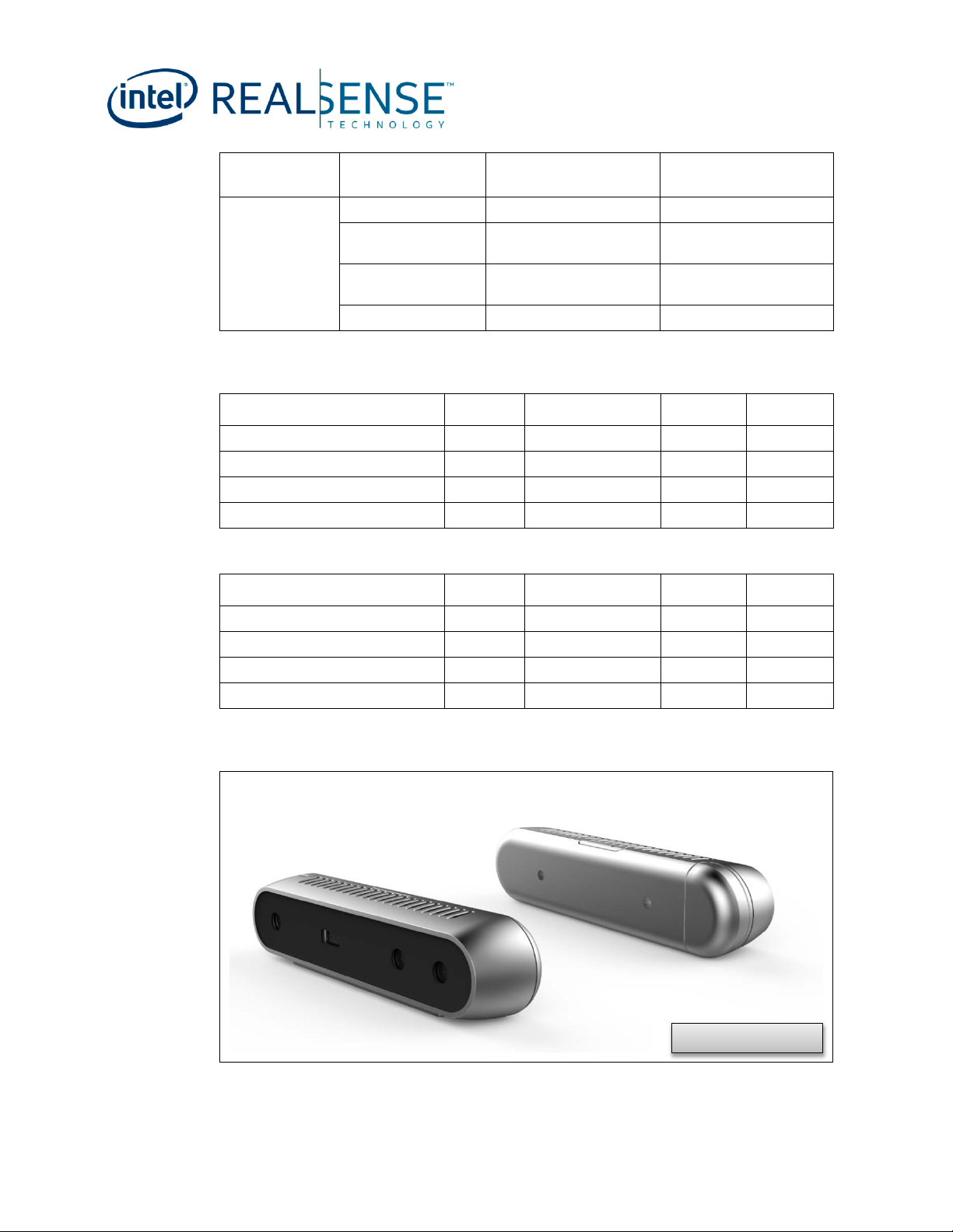
Table 2-2. Intel® RealSense™ Depth Ca mera D415 Mechani c a l Dimensions
Dimension Min Nominal Max Unit
Width 99 mm
Height 23 mm
Depth 20 mm
Mass 72 gr
Table 2-3. Intel® RealSense™ Depth Ca mera D435 Mechani c a l Dimensions
Dimension Min Nominal Max Unit
X
√
Width 90 mm
Height 25 mm
Depth 25 mm
Mass 72 gr
Figure 2-1. Intel® RealSenseTM Depth Camera D415
10 Datasheet
Page 11

Not Final Version
Introduction
Figure 2-2. Intel® RealSenseTM Depth Camera D435
2.5 Stereo Vision Depth Technology Overview
The Intel® RealSense™ depth c a m er a D400 s er ies uses stereo vision to calculate
depth. The stereo vision implementation consists of a left imager, right imager, and an
optional infrar e d p r ojector. The infr a r e d p r oj ector projects non-visible static IR pattern
to improve depth accuracy in scen es with low texture. The left and right imagers
capture the scene and sends im a ger da ta to the depth imaging processor, which
calculates depth values for each pix el in the image by correlating points on the left
image to the right image and via shift between a point on the Left image a nd the
Right image. The depth pixel values are processed to generate a depth frame.
Subsequent depth frames create a depth video stream.
Datasheet 11
Page 12

Figure 2-3. Active Infrared (IR) Stereo Vision Technolo gy
Image
Sensors
IR Projecto r
1) Capt ure
2) Search
3) Depth
The depth pixel value is a measur em ent from the parallel plane of the imagers a nd not
the absolute range a s illustrated.
Figure 2-4. Depth Measurement (Z) Versus Range (R)
Introduction
2.6 D400-Series Camera Block Diagram
The D400-Series Cameras has 2 main components, Vision Processor, and Depth
Module. The Vision Process or referred as Intel® RealSense™ Vision Proc essor D4 is
connecting to the host processor through USB 3.0. The Depth Module incorporates the
left and right imagers with the IR projec tor and RGB color sensor. The RGB color
sensor data is sent to the Vision Processor v ia the color Image Signal Processor (ISP).
12 Datasheet
Page 13

Introduction
Figure 2-5. D415/D435 Sy stem Block Diagram
2.7 Depth Module
The Depth Module componen ts a r e des c r ibed in T a ble 2-4. The Depth camera printed
circuit board and components are encapsulated in a common metal stiffener.
Datasheet 13
Page 14

Table 2-4. Depth Module
Right Imager Left ImagerIR Projector
Camer a
Connector
Module Label
Component Description
Left & Right Imagers 2 1080p image sensors
Infrared (IR) Projector Class 1 laser compliant
Color Camera 1080p RGB image sensor
Stereo Camera Connector 50 pin connector plug
Privacy LED Indicator when stereo module is streaming data
Stiffener Reinforcement housing to keep imagers alig ne d
Label Manufacture and product identifier info r m ation
Other Components Laser Driver, EEPROM, Voltage Regulators , e tc .
Figure 2-6. Depth Module in D415 (Intel® RealSense™ Depth Module D415)
Introduction
Figure 2-7. Depth Module in D435 (Intel® RealSense™ Depth Module D430)
14 Datasheet
Page 15

Introduction
Table 2-5. Depth Module SKU Propertie s
D400-Series Depth Cameras
Depth module
Baseline 55mm 50mm
Left/Right Imagers Type Standard Wide
Left/Right Imagers FOV
(degrees)
IR Projector Standard Wide
IR Projector FOV H:80 / V:55 /D:89.3 H:100.4/V:69/D:110.4
Color Sensor OV2740 OV2740
Color Camera FOV H:69.4 / V:42.5/ D:77 H:69.4 / V:42.5/ D:77
Depth Module Dimensions
(mm)
Intel® RealSense™ Depth
Intel® RealSense™ Depth
H – Horizontal FOV , V – Vertical FOV, D – Diagonal FOV, X – Length, Y – Bre a d t h, Z –
Thickness
2.7.1 Left and Right Imagers
The Depth Module has two camera sensors referred here as stereo imagers, they are
identical parts and are con figured with identical settin gs . The imagers are labeled
“left” and “right” from the perspective of the camera module looking outward. The
stereo imager pairs are ref er r ed a s Standard and Wide based on imager field of view.
Camera D415
Module D415
H:69.4 / V:42.5/ D:77 H:91.2 / V:65.5 / D:100.6
X=83.7mm Y=10mm
Z=4.7mm
Intel® RealSense™ Depth
Camera D435
Intel® RealSense™ Depth
Module D435
X=70.7mm Y=14mm
Z=10.53mm
Datasheet 15
Page 16

Table 2-6. Standard Left and Right Image r P roperties (f or D4 15)
Parameter Camera Sensor Prop er ti e s
Image Sensor OV2740
Active Pixels 1920 × 1080
Sensor Aspect Ratio 16:9
Format 10-bit RAW
F Number f/2.0
Focal Length 1.88mm
Filter Type None
Focus Fixed
Shutter Type Rolling Shutter
Signal Interface MIPI CSI-2, 2X Lanes
Horizontal Field of View 69.4o
Vertical Field of View 42.5o
Diagonal Field of View 77o
Distortion <=1.5%
Introduction
Table 2-7. Wide Le ft and Right Imager Prope r ties (for D435)
Parameter Camera Sensor Propert i es
Image Sensor OV9282
Active Pixels 1280 X 800
Sensor Aspect Ratio 8:5
Format 10-bit RAW
F Number f/2.0
Focal Length 1.93mm
Filter Type None
Focus Fixed
Shutter Type Global Shutter
Signal Interface MIPI CSI-2, 2X Lanes
Horizontal Field of View 91.2o
Vertical Field of View 65.5o
Diagonal Field of View 100.6o
Distortion <=1.5%
16 Datasheet
Page 17

Introduction
2.7.2 Infrared Projector
The infrared projector improves the a bility of the Depth module to determine depth by
projecting a static infrared pattern on the scene to increase texture on low text ure
scenes. The infrared projector meets class 1 laser safety under normal operation. The
power delivery and laser saf ety c ir c uits are on the Depth Module.
Table 2-8. Standard Infrare d P roje ctor Parameters
Parameter Properties
Projector Infrared
Pattern Type Static
Illuminating Component Vertical-cavity surface -emitting laser (VCSEL) + Optics
Laser Controller PWM
Optical Power 350mW average, 440mW peak
Laser Wavelength 850nm ± 10 nm nominal @ 20°C
Laser Compliance Class 1, IEC 60 825-1:2007 Edition 2, IEC 60825-1:2014
Edition 3
Horizontal Field of Projection 80o
Vertical Field of Projection 55o
Diagonal Field of Projection 89.3o
Table 2-9. Wide Infrared P roje ctor Parameters
Parameter Properties
Projector Infrared
Pattern Type Static
Illuminating Component Vertical-cavity surface -emitting laser (VCSEL) + optics
Laser Controller PWM
Optical Power 350mW average, 4.25W peak
Laser Wavelength 850nm ± 10 nm nominal @ 20°C
Laser Compliance Class 1, IEC 60 825-1:2007 Edition 2, IEC 60825-1:2014
Edition 3
Horizontal Field of Projection 100.4o
Vertical Field of Projection 69o
Diagonal Field of Projection 110.4o
2.7.3 Color Camera
The color camera on the depth module in addition to color imag e pr ovides texture
information. Us a g es for the texture inf ormation include ov er lay on a depth image to
create a color point cloud and overlay on a 3D model for reconstr uction.
Datasheet 17
Page 18

Table 2-10. Color Senso r P roperties
Parameter Camera Sensor Prop er ti e s
Image Sensor OV2740
ISP Discrete
Active Pixels 1920 X 1080
Sensor Aspect Ratio 16:9
Format 10-bit RAW RGB
F Number f/2.0
Focal Length 1.93mm
Filter Type IR Cut Filter
Focus Fixed
Shutter Type Rolling Shutter
Signal Interface MIPI CSI-2, 1 Lane
Vertical Field of View 69.4o
Horizontal Field of View 42.5o
Diagonal Field of View 77o
Distortion <=1.5%
Introduction
2.8 Color Image Signal Processor (ISP)
The RGB sensor on the depth module sends color data to discrete Im age Signal
Processor (ISP) for image adjustments, image scaling and processing functions to help
compensate for inherent in a c c uracy in lens and sensor in providing a better im age
quality. The proces s ed c olor image is sent to the Intel® RealSense™ Vision Proce s sor
D4.
Table 2-11. ISP Propertie s
Parameter ISP Properties
ISP Part Number on Intel® RealSense™
Vision Process or D4 Card
1M-bit Serial Flash for ISP Winbond* W25X10CL or equivalent
Interface To Intel® RealSense™ Vision
Processor D4
Interface To RGB Sensor MIPI CSI-2, 1X Lane
RTS5845
MIPI CSI-2, 2X Lanes
2.9 Intel® RealSense™ Vision Processor D4 Card
The Intel® RealSense™ Vision Processor D4 Card enables an easy and quick option
for system integrators to integrate I ntel® RealSense™ Vision Processor D4 in to a
system.
18 Datasheet
Page 19

Introduction
Table 2-12. Intel® R ealSense™ Vis ion Processor D4 Card Components
Components Description
The Intel RealSense Vision Processor D4 is a
Intel® RealSense™ Vision Processor
D4
16Mb Serial Flash
24MHz Crystal Clock source for Vision Processor
Realtek* ISP with external serial flash Color im age sig nal pr oce ssor
Camera Receptacle 50 pin receptacle for connectio n to Dep th Module
Tracking Module Receptacle
USB Type-C
External Sensor Sync Connector Interface to external sensor interrupts/sync signals
Voltage Regulators
Mounting holes
purpose-built ASI C for com p uting r e al tim e depth
and accelerating computer vision, at sig ni f ic a ntly
faster speeds and fraction of the power compared
to host based compute.
Intel® RealSense™ Vision Processor D4 firmware
storage
50 pin connector receptacle for connection to
Tracking Module and/or RGB sensor
USB peripheral connector for connection to Host
USB3.0 port
DC to DC converters powering Intel® RealSense™
Vision Processor D4 Card, Depth Module and
Tracking Module
Intel® RealSense™ Vision Processor D4 Card
secure mounting
Figure 2-8. Intel® Real S e nse™ Vision Processor D4 Card
2.9.1 Power Requirements
The Depth Camera is powered th r ou gh VBUS power of the USB connector. The Intel®
RealSense™ Vision Proces s or D 4 C a r d in turn power sources the Depth Module.
Datasheet 19
Page 20

Table 2-13. Power Requirements
Parameter Min Nom Max Unit
VCC Supply Voltage +/-5% 5 V V
ICC Supply Current 700 mA
2.10 D400-Series Depth Cameras Thermals
Table 2-14. Max Skin Temperature
Max Skin Temperature
D400-Series Depth Cameras
D415 43 oC (estimated)
D435 44 oC
(25 oC Ambiance
at Open Environment)
Introduction
2.11 Storage and Operating Conditions
Table 2-15. Storage and Operat ing Conditions
Condition Description Min Max Unit
Storage (Ambient), Not Operating Temperature -40
Humidity Temperature/ RH: 40oC / 90%
Operating
NOTE: Component case temperature limits must be met for all operating te m p er atures.
(1)
(Ambient) Temperature
0 35
§ §
70
o
C
o
C
20 Datasheet
Page 21

Functional Specificatio n
3 Functional Specification
3.1 Depth Camera
Intel® RealSense™ Depth Camera D400 series provides high quality depth data to a
host system. The depth data is generated with stereo vision tec hnology that is
optionally assisted by an infrared laser projector. Intel® RealSense™ Depth Camera
D400 series has the ability to syncr onize with Color camera streams.
Table 3-1. Intel® Re alSense™ Depth Camera D400 Series Image Formats
Format Resolution Frame Rate Comment
1280x720 6,15,30
848X480 6,15,30,60,90
Z [16 bits]
Y8 [8 bits]
L_UYVY [16 bits]
RY8_LY8 [16 bits]
YUY2
Calibration [24 bits]
RY8_LY8 [16 bits] 1920x1080 25,15 Dynamic Calibr ation for D415
640x480 6,15,30,60,90
640x360 6,15,30,60,90
480x270 6,15,30,60,90
424x240 6,15,30,60,90
1280x720 6,15,30
848X480 6,15,30,60,90
640x480 6,15,30,60,90
640x360 6,15,30,60,90
480x270 6,15,30,60,90
424x240 6,15,30,60,90
1920x1080 6,15,30
1280x720 6,15,30,60
960x540 6,15,30,60
848x480 6,15,30,60
640x480 6,15,30,60
640x360 6,15,30,60
424x240 6,15,30,60
320x240 6,15,30,60
320x180 6,15,30,60
1920x1080 25,15
960x540 30,15
1280x800 30,15
640x400 30,15
Depth Only Mode
Illumination Mode Only
Color channel
Intel® RealSense™ Camera
Intel® RealSense™ Camera
D415
D435
Datasheet 21
Page 22

Functional Specificatio n
Gain are set based on the environment
Format Resolution Frame Rate Comment
RY8_LY8 [16 bits] 1280x800 30,15 Dynam ic Calibration for D435
NOTE: Depth/RGB are mapped as separated interfaces. The two interfaces work independently
from each other (Virtual c ha nnel in MI PI and End Poi nt in USB).
3.2 Depth Camera Functions
Intel® RealSense™ Depth Camera D400 series exposes th e following Depth ima ge
settings.
Table 3-2. Depth Came ra Controls
Control Description Min Max Default
Manual Exposure
Manual Exposure
Manual gain
(Gain 1.0 = 16)
Laser Power (on/off)
(On = 1)
Manual Laser Power (mW) Laser Power setting (30mW steps) 0 360 240
Auto Exposur e Mod e
(Enable = 1)
Auto Exposure ROI Perform Auto Exposure on a selected
Preset S e t Controls parameters based on
(1)
(ms) Control sensor exposure period (D415)
(1)
(ms) Control sensor exposure period (D435)
(1)
Control sensor digital gain. 16 248 16
Power to IR Projector 0 1 1
Auto Exposure Mode. When Auto
Exposure is enabled, Exposure and
condition
ROI
Camera Usage
1 166 10
1 166 2
0 1 1
T-0
L-0
B-1
R-1
T-719
L-1279
B-720
R-1280
T-0
L-0
B-1
R-1
NOTES:
22 Datasheet
(1)
1.
Not supported in Auto Exposure Mode
2. T - Top, L – Left, B - Bottom, R – Right
Page 23

Functional Specificatio n
3.3 Color Camera Functions
Table 3-3. RGB (Integrated) Exposed Cont rols
Control Description Min Max Default
Auto-Exposure Mode Automatically sets the exposure time
Auto-Exposure Priority The setting for the attribute of the
Manual Exposure Time Sets the absolute exposure time when
Backlight Compensation Sets a weighting amount based on
Brightness Sets the amount of brightness applied
Contrast Sets the amount of contrast based on
Gain Sets the amount of gain applied to the
Power Line Frequency Specified based on the local power line
Hue Sets the amount of hue adjustment
Saturation Sets the amount of saturation
Sharpness Sets the amount of sharpening
Gamma Sets amount of gamma corre ction
White Balance
Temperature Control
White Balance
Temperature Auto
(AWB)
and gain for the frame.
addressed Auto-Exposure Priority
control.
auto-exposure is disabled.
brightness to the frame.
when auto-exposure is enabled.
the brightness of the scene.
frame if auto-exposure is disabled.
frequency for flicker avoidance.
applied to the frame.
adjustment applied to the frame.
adjustment applied to the frame.
applied to the frame.
Sets the white balance when AWB is
disabled.
Enables or disables the AWB
algorithm.
§ §
Datasheet 23
Page 24

Software Package
4 Software Package
4.1 Intel® RealSense™ Software Development Kit 2.0
Intel® RealSense™ Sof twar e Development Kit 2.0 (SDK 2.0) also k nown as
LibRealSense, is cross-platform and open sou r ce. The SDK contains tools, code
examples and multiple languages wrappers to extract data fr om the Intel®
RealSense™ depth cameras .
Intel® RealSense SDK 2.0 supports the D415 and D 435 C a m er a .
The SDK is compris e d of the following main S W components:
Tools directory :
• Intel® RealSense™ Viewer
of the RealSense camera.
• Depth Quality T est tool for Intel® RealSense™ Camera – A GUI based
application f or te s ting the camera’s depth quality
– A GUI based application for a quick evaluation
Debug tools: please use these tools for getting logs or fu r ther information for
debugging your application.
Examples direct or y: Simple applications that demonstra te how to easily use th e SDK
APIs to build applic a tions.
Wrappers directory: Wra pper s s upporting common programming languages and
environments.
The Intel® RealSense™ SD K 2.0 can be found on GitHub:
https://github.com/IntelRealSense/librealsense
§ §
24 Datasheet
Page 25

Firmware
5 Firmware
The firmware contains the operation instructions. Up on runtime, Intel® RealSense™
Depth Camera D400 series loads the firmware and programs the componen t r egisters.
If the Intel® RealSense™ Depth Camera D400 series is configured for update or
recovery, the unlock ed R /W r egion of the firmware can be changed.
5.1 Firmware Update
During a firmware update, the Device Firmware Upda te tool for Intel® RealS ense™
technology will iss ue a device firmware update comm a nd to the RealSense D400
series Depth Camera. The RealSense D400 seri es Depth Camera will then r es e t into
firmware update mode. The D ev ic e F ir mware Update tool for Intel® RealS ense™
technology uses a single binary file to maintain the firmwa r e im a g e. The Device
Firmware Update t ool for Intel® RealSense™ technology com pares the firmware
version installed on the camera to the firmware version f ile to be updated. Based on
the comparison, the Device Firmwar e U pd a te tool for Intel® Rea lSense™ technology
will downgrade, upgrade, or skip if the versions match.
The device firmware upda te too l a nd firmware binary will be located at the
https://downloadcenter.intel.com/
5.1.1 Update Limits
The firmware update engine does not allow infinite update cycles betw een older and
current versions of firmware. The engine will establish a baseline version of firmware
based on the latest f ir m ware version ins talled. The engine will a llow a return to a
previous version or baseline version of firmware up to 20 times. After the 20th
update, the engine will only allow an update to a firmware revision higher than the
baseline version.
5.2 Recovery
A read only boot sector is built into firmware which enables ba s ic operation regardless
of the integrity of the operation instructions region. This ensures the ima g ing system
can function in the case of firmware not b e written properly. W hen a firmware
recovery is required, the Dev ic e F irm ware Update tool for Intel® RealSense™
technology will c om municate with the r ec ov er y driver to set the DFU pin low and reset
the imaging system in recovery mode.
Firmware Recove r y can also be externally tr iggered by having controllable interrupt
connected to the Intel® RealSense™ Vision Processor D4 DFU (Device Firmware
Update) pin.
The firmware recovery sequence will be triggered by the firmwa r e c lien t u tility. This
client utility will communicate through ACPI _DSM to trigger the controllable in terrupt
(GPIO) at the appropriate times. T he firmware recovery requires an AC PI _DSM
interface to control the interrupt GPIO in configurin g to fir m ware recovery state. The
_DSM methods and BIOS use the Write to GPI O functions to set the controllable
interrupt.
§ §
Datasheet 25
Page 26

6 Calibration Support
The Intel® RealSense™ Depth C a m er a D415/ D 435 can be connected to P C to retrieve
and write camera calibration parameters via the host system.
6.1 Dynamic Calibration Tool
The name of the tool is: Intel® RealSense™ Dynamic Calibrator , please find it on
https://downloadcenter.intel.com/
There are two types of dynamic calibrations that ar e supported by the tool:
1. Targeted Dynamic Calibration (Depth S cale Calibration)
2. Target-less Dynamic Calibration (Rectif ic ation Calibration)
Refer to the user guide of In tel® R ea lS ense™ Dynamic Calibrator for further
information.
Calibration Support
§ §
26 Datasheet
Page 27

CLASS 1 LASER PRODUCT
EN/IEC 60825-1, 2014 (EU & other)
IEC 60825-1, 2007 (US)
This d evice co mplie s with U S FDA p erformance standard s for laser pr oduct s
except for de viations pur suant to Laser Notice No. 50 dat ed June24 , 2007.
Regulatory Compliance
7 Regulatory Compliance
7.1 System Laser Compliance
The Intel® RealSense™ Depth C a m er a D400-series certificat ion is transferable to the
system and no sys te m r e c ertification is requir ed. However, the following statements
and labels must be included in the user manual of the end product
7.1.1 Certification Statement
This product is classified as a Class 1 Laser Product under the EN/IEC 60825-1, Edition
3 (2014) internationally a nd IEC60825-1, Edition 2 (2007) in the US .
This product complies with US FDA per formance standards under 21 CFR 1040.10 for
laser products except for deviations pursuant to Laser Notice N o. 50 da ted June 24,
2007.
7.1.2 Explanatory Label
7.1.3 Cautionary Statements
System integrators should refer to th eir respective regu latory and
compliance owner to finalize regulator y requirements f or a specific
geography.
CAUTION - Use of controls or adjustments or performance of
procedures other than those specified herein may result in hazardous
radiation exposure.
Datasheet 27
Page 28

7.1.4 Safety and Handling Instructions:
specific camera module SKU and revision.
- Do not power on the product if a ny external damage was observed.
- Do not attempt to open any portion of this la s e r product. There are no
user serviceable parts.
- Invisible laser radiation when opened. Avoid direct exposure to beam .
- Do not modify or ser vice the product in an y way. Modification or
service of the hardwar e might cause the emissions to exceed th e Class 1
level.
- No magnifyin g op tic al elements, such a s e ye loupes and magnifiers,
are allowed.
- Do not try to update camera firmware that is not officially r eleased for
7.1.5 Manufacturer’s Information
Regulatory Compliance
• Manufactured by Intel Corporation
• 2200 Mission College Blvd., S a nta Clara, CA 95054 USA
7.1.6 US FDA Accession Number
Camera US FDA Accession Numbers
Intel® RealSenseTM Depth Camera D415 1420260-006
Intel® RealSenseTM Depth Camera D435 1420260-007
This accession number should be entered into Box B.1 of the Food and Drug
Administration ( FDA) 2877 Declarati on for Imported Electronic Products Subject to
Radiation Contr ol Standards.
28 Datasheet
Page 29

electronic information products, as of the date of sale of the enclosed product.
Regulatory Compliance
7.2 Ecology Compliance
China RoHS Declara t ion
产品中有毒有害物质的名称及含量
Hazardous Substances Table
部件名称
Component Name
相机
Camera
印刷电路板组件
Printed Board Assemblies
三角架
Tripod
电缆
铅
Pb
X ○ ○ ○ ○ ○
X ○ ○ ○ ○ ○
○ ○ ○ ○ ○ ○
○ ○ ○ ○ ○ ○
有毒有害物质或元素 Hazardous Substance
汞
Hg
镉
Cd
六价铬
Cr (VI)
多溴联苯
PBB
多溴二苯醚
PBDE
Cable
○:表示该有毒有害物质在该部件所有均质材料中的含量均在GB/T 26572标准规定的限量要
求以下。
○:Indicates that this hazardous substance contained in all homogeneous
materials of such component is within the limits specified in GB/T 26572.
×:表示该有毒有害物质至少在该部件的某一均质材料中的含量超出GB/T 26572标准规定的
限量要求。
×: Indicates that the content of such hazardous substance in at least a
homogeneous material of such component exceeds the limits specified in GB/T
26572.
对销售之日的所售产品,本表显示我公司供应链的电子信息产品可能包含这些物质。注
意:在所售产品中可能会也可能不会含有所有所列的部件。
This table shows where these substances may be found in the supply chain of our
Note that some of the component types listed above may or may not be a part of
the enclosed product.
除非另外特别的标注,此标志为针对所涉及产品的环保使用期限标志. 某些可更换的零
部件可能会有一个不同的环保使用期限(例如,电池单元模块).
此环保使用期限只适用于产品在产品手册中所规定的条件下工作.
Datasheet 29
Page 30

Regulatory Compliance
The Environment-Friendly Use Period (EFUP) for all enclosed products and their
parts are per the symbol shown here, unless otherwise marked. Certain fieldreplaceable parts may have a different EFUP (for example, battery modules)
number. The Environment-Friendly Use Period is valid only when the product is
operated under the conditions defined in the product manual.
“In the EU, this symbol means that this product must not be disposed of
with household waste. It is your responsibility to bring it to a designated
collection point for the recycling of waste electrical and electronic
equipment. For more information, please contact your local waste
collection center or your point of purchase of this product.”
§ §
30 Datasheet
Page 31

Mechanical Drawings
8 Mechanical Drawings
Figure 8-1. Intel® Real S e nse™ Depth Camera D415
Datasheet 31
Page 32

Figure 8-2. Intel® Real S e nse™ Depth Camera D435
Mechanical Drawings
§ §
32 Datasheet
 Loading...