

Page 1

Distributed by:
Jameco Part Number 875982
www.Jameco.com ✦ 1-800-831-4242
The content and copyrights of the attached
material are the property of its owner.
Page 2

82559 Fast Ethernet Multifunction
PCI/CardBus Controller
Stepping Information
October 2004
Revision 2.2
Notice: The 82559 Fast Ethernet Multifunction PCI/CardBus Controller may contain design
defects or errors known as errata which may cause the product to deviate from published
specifications. Current characterized errata are documented in this specification update.
Page 3

Information in this document is provided in connection with Intel® products. No license, express or implied, by estoppel or otherwise, to any intellectual
property rights is granted by this document. Except as provided in Intel's Terms and Conditions of Sale for such products, Intel assumes no liability
whatsoever, and Intel disclaims any express or implied warranty, relating to sale and/or use of Intel products including liability or warranties relating to
fitness for a particular purpose, merchantability, or infringement of any patent, copyright or other intellectual property right. Intel products are not
intended for use in medical, life saving, or life sustaining applications.
Intel may make changes to specifications and product descriptions at any time, without notice.
Designers must not rely on the absence or characteristics of any features or instructions marked "reserved" or "undefined." Intel reserves these for
future definition and shall have no responsibility whatsoever for conflicts or incompatibilities arising from future changes to them.
The 82559 Fast Ethernet Multifunction PCI/CardBus Controller may contain design defects or errors known as errata which may cause the product to
deviate from published specifications. Current characterized errata are available on request.
Contact your local Intel sales office or your distributor to obtain the latest specifications and before placing your product order.
Copies of documents which have an ordering number and are referenced in this document, or other Intel literature may be obtained by calling 1-800548-4725 or by visiting Intel's Web site at http://www.intel.com.
Copyright © 2004, Intel Corporation.
* Other product and corporate names may be trademarks of other companies and are used only for explanation and to the owners’ benefit without
intent to infringe.
82559 Stepping Information
Page 4

Contents
Revision History ........................................................................................................................................ 1
Preface ...................................................................................................................................................... 1
Nomenclature ............................................................................................................................................ 1
Identification Information............................................................................................................................3
82559 Component Marking Identification ..................................................................................... 3
82559 Component Programming Interface Identification ............................................................4
Summary Table of Changes ...................................................................................................................... 4
Specification Changes................................................................................................... 6
1. Removal of Internal Pull-up Resistor from Isolate Pin ..................................................... 6
2. Unsupported End of List Bit in High Priority Queues ....................................................... 6
3. Supported Total Cost of Ownership (TCO) Frame Formats ............................................ 6
4. Deep Power-Down Current Consumption .......................................................................6
Errata............................................................................................................................. 7
1. Base Registers Restore After a Selective Reset ............................................................. 7
2. Base Registers Initialization Changes ............................................................................. 7
3. Receive Total Cost of Ownership (TCO) Packets Truncation .........................................7
4. Corrupted Byte Count on System Management Bus (SMB) upon Reset ........................ 8
5. Corrupted Alert Response Address on System Management Bus on Software Reset ...8
6. Premature Clamping of Electrostatic Discharge Circuitry................................................8
7. False Power Management Event Indication on Power Cycle ..........................................9
8. Modem Interrupt Propagation........................................................................................10
9. Corrupted PCI Burst Read with D0 System Management Bus Receive........................10
10. Programmable Filter Corruption ....................................................................................10
11. Invalid Alert Response Address (ARA) Return .............................................................. 11
12. Potential Receive Overrun in Dynamic Standby Mode..................................................11
13. False Detection of Security ASIC .................................................................................. 13
Specification Clarifications .......................................................................................... 14
1. 82559 Initialization During System Management Bus (SMB) Access ...........................14
2. 82559C Compliance ...................................................................................................... 14
3. Link Loss Deep Power-Down Noise Sensitivity ............................................................. 14
4. PCI Buffer Leakage When the Voltage Input/Output Pin (VIO) Not Powered ...............14
5. Load and Start Receive Unit Commands in IP Security Applications............................15
Documentation Changes............................................................................................. 16
1. 82559 LAN on Motherboard Design Guide.................................................................... 16
2. Software Technical Reference Manual..........................................................................17
82559 Stepping Information iii
Page 5

3. 82559 Fast Ethernet Controller Datasheet .................................................................... 17
iv 82559 Stepping Information
Page 6

Revision History
Date Version Description
Oct 2004 2.2
Mar. 2002 2.1 • Updated “82559 Component Marking Identification”.
Feb. 2002 2.0
Mar. 2001 1.6
Apr. 2000 1.5
May 1999 1.3 Added B-step clamping erratum.
Nov. 1998 0.8 Added clarification material.
Oct. 1998 0.7 Initial release.
• Removed Intel Confidential status.
• Removed references to A3 stepping, which does not exist.
• Added Specification Change 4, “Deep Power-Down Current Consumption”
and Errata 12, “Potential Receive Overrun in Dynamic Standby Mode” and
Errata 13, “False Detection of Security ASIC”.
• Changed references to Software Developer’s Manual (SDM) to Software
Technical Reference Manual (STRM).
• Added 82559 Fast Ethernet Controller Datasheet to the Document Changes
section.
• Combined Revision 1.3 of this document with 82559C Stepping Information
document.
• Revised tables in Identification Information section to reflect correct stepping
information and revision numbers.
• Updated document format to comply with current corporate templates.
Preface
This document is an update to the specifications contained in the Intel® 82559 Fast Ethernet
Multifunction PCI/CardBus Controller Data Sheet, and contains issues affecting all design using
the 82559 device.
This document is intended for hardware system manufacturers and software developers of
applications, operating systems or tools. It contains Specification Changes, Errata, Specification
Clarifications, and Document Changes.
All changes, errata, and clarifications described in this document will be incorporated into the next
release of the 82559 Fast Ethernet Multifunction PCI/CardBus Controller Data Sheet.
Nomenclature
Specification Changes are modifications to the current published specifications. These changes
will be incorporated in the next release of the specifications.
Errata are design defects or errors.
published specifications. Hardware and software designed to be used with any given stepping must
assume that all errata documented for that stepping are present on all devices.
Specification Clarifications describe a specification in greater detail or further highlight a
specification’s impact to a complex design situation.
next release of the specifications.
Errata may cause the 82559’s behavior to deviate from
These clarifications will be incorporated in the
82559 Stepping Information 1
Page 7

Documentation Changes include typos, errors, or omissions from the current published
specifications. These changes will be incorporated in the next release of the specifications.
2 82559 Stepping Information
Page 8
Identification Information
82559 Component Marking Identification
Device Stepping Top Marking Q-specification MM Number Notes
82559 B1 - 3 GD82559 Q405 MM818501 Engineering samples
82559 B5 GD82559 STD MM821112 No longer in production.
82559 B5 GD82559 Q406 MM821144 Production samples (tray)
82559 B5 GD82559 SL3Q3 MM825117 Production (tape and reel)
82559 B5 GD82559 SL3HD MM822772 Production (tray)
82559C A2 GD82559C STD MM824178 Production (tape and reel)
82559C A2 GD82559C Q408 MM825112 Production (tray)
82559C A2 GD82559C SL3DF MM822048 Production (tray)
GD82559C
FFFFFFFF
M C '99
KOREA
FFFFFFFF FPO numbers
82559 Stepping Information 3
Page 9

82559 Component Programming Interface Identification
Device Stepping Vendor ID Device ID
82559 B5 8086h 1229h 07h
82559C A2 8086h 1229h 08h
Summary Table of Changes
The following table indicates the Specification Changes, Errata, Specification Clarifications or
Documentation Changes, which apply to the listed 82559 steppings. Intel intends to fix some of the
errata in a future stepping of the component and to account for other outstanding issues through
documentation or Specification Changes as noted. This table uses the following notations:
Codes used in summary table:
X:
Doc: Document change or update that will be implemented.
Fix: This erratum is intended to be fixed in a future stepping of the component.
Fixed: This erratum has been previously fixed.
NoFix: There are no plans to fix this erratum.
Eval: Plans to fix this erratum are under evaluation.
(No mark) or (Blank box): This erratum is fixed in listed stepping or specification change does not apply to
Shaded: This Item is either new or modified from the previous version of the document.
Specification Change, Erratum, or Specification Clarification that applies to this
stepping.
listed stepping.
Revision
Number
B1-
No.
1 XX DS 1.0Removal of Internal Pull-up Resistor from Isolate Pin 6
2 XSTRM 1.2Unsupported End of List Bit in High Priority Queues 6
3 XSTRM 1.2Supported Total Cost of Ownership (TCO) Frame Formats 6
4 X
No.
1 XXX NoFixBase Registers Restore After a Selective Reset 7
2 XXX NoFixBase Registers Initialization Changes 7
3 XXX NoFixReceive Total Cost of Ownership (TCO) Packets Truncation 7
4 XXX NoFix
5 XXX NoFix
B5 A2
B3
B1-
B5 A2 Plans ERRATA Page
B3
a
Plans SPECIFICATION CHANGES Page
DS 2.2
STRM 1.2
Deep Power-Down Current Consumption 6
Corrupted Byte Count on System Management Bus (SMB)
upon Reset
Corrupted Alert Response Address on System Management
Bus on Software Reset
8
8
4 82559 Stepping Information
Page 10

6 XX Fix Premature Clamping of Electrostatic Discharge Circuitry 8
7 XXX NoFixFalse Power Management Event Indication on Power Cycle 9
8 XNoFixModem Interrupt Propagation 10
9 XNoFix
10 XNoFixProgrammable Filter Corruption 10
11 XNoFixInvalid Alert Response Address (ARA) Return 11
12 XX Fix Potential Receive Overrun in Dynamic Standby Mode 11
13 XNoFixFalse Detection of Security ASIC 13
B1-
No.
1 X
2 X 82559C Compliance 14
3 X Link Loss Deep Power-Down Noise Sensitivity 14
4 X
5 X
No.
1 AP-392 1.3 82559 LAN on Motherboard Design Guide 16
2 STRM 1.3 Software Technical Reference Manual 17
3 DS 2.2 82559 Fast Ethernet Controller Datasheet 17
a. The A2 stepping is more commonly known as the 82559C.
B5 A2 Plans SPECIFICATION CLARIFICATIONS Page
B3
B1-
B5 A2 Plans DOCUMENTATION CHANGES Page
B3
Corrupted PCI Burst Read with D0 System Management
Bus Receive
82559 Initialization During System Management Bus (SMB)
Access
PCI Buffer Leakage When the Voltage Input/Output Pin
(VIO) Not Powered
Load and Start Receive Unit Commands in IP Security
Applications
10
14
14
15
NOTE: The table uses the following abbreviations for listed documents.
DS: Data Sheet
STRM: Software Technical Reference Manual
EDS: External Data Specification
AP: Application Note
82559 Stepping Information 5
Page 11

Specification Changes
Specification Changes
1. Removal of Internal Pull-up Resistor from Isolate Pin
Explanation: In systems that support wake-up in a low power state, the 82559 can be powered while the PCI bus
is undefined. In this instance the Isolate pin is used to signal the 82559 that the PCI signals may be
ignored.
Implication: The PCI reset does not initialize the 82559 while operating from an auxiliary power source.
Instead, the bus reset or a transition on the Isolate pin switches the device from the D3 power state
to the D0 power state. LAN on Motherboard (LOM) designs may use a signal such as the
SUSSTAT to drive the Isolate pin. However, this option is not available for PCI add-on cards. One
possible option uses the PCI Reset signal. The PCI Reset signal is asserted low by the system prior
to bus suspension to indicate a pending event on the Isolate pin. Since the Reset pin is not actively
driven low following shutdown, the internal pull-up resistor violates PCI requirements if it is used
with earlier stepping devices as an isolate signal.
Status: The internal pull-up resistor was removed in the 82559 B5 stepping. This change was reflected in
the Intel
2. Unsupported End of List Bit in High Priority Queues
Explanation: If High Priority Queue (HPQ) is used, the End of List (EL) bit in the command word of an HPQ or
Low Priority Queue (LPQ) is not supported as an identification for the end of the Command Block
List (CBL). Software drivers should only use the Start (S) bit in the header to identify the end of a
CBL in a HPQ.
Implication: This change affects drivers that add support for multiple priority queues.
®
82559 Fast Ethernet Multifunction PCI/CardBus Controller Data Sheet, Revision 1.0.
Status: The appropriate definition changes were made to all relative 82559C documents.
3. Supported Total Cost of Ownership (TCO) Frame Formats
Explanation: The 82559C device only supports UPD format Total Cost of Ownership (TCO) frames. It does not
support TCP format TCO frames. This occurs because the 82559 filters for protocol number 04h
(UDP protocol number) instead of 06h (TCP protocol number) in the Protocol field of the IP
header. The TCP format TCO frames contain an error in the Protocol field.
Implication: The TCO format defined for the 82559C is defined as TCO messages that conform to a UDP
packet type. This includes support for Alert on LAN* technology UDP packet type.
Status: The appropriate definition changes were made to all relative 82559C documents.
4. Deep Power-Down Current Consumption
Explanation: The documented specification for current consumption in the deep power-down mode was 3 mA.
This is incorrect and should read 6.5 mA as per device performance.
The deep power-down mode is entered at the D2 or D3 power management state when the link is
down. Deep Power
The General Control Register (base offset + 1Ch, bit 1) must be set to 1b to enable this mode.
Implication: The impact of this update is limited to the most power-conscious mobile platforms.
6 82559 Stepping Information
Page 12

Errata
Errata
1. Base Registers Restore After a Selective Reset
Problem: The 82559 is Intel’s third generation Fast Ethernet Controller. (The first was the 82557.) The
contents of the Receive Unit (RU) and Command Unit (CU) base registers of the 82557 are
retained on a Selective Reset from the driver. The addition of the System Management Bus (SMB)
port functionality in the 82559 allows both status and receive traffic on the SMB interface. A Port
Command, such as a Selective Reset, clears the base registers in a Total Cost of Ownership (TCO)
environment with this port functionality enabled. Software must initialize these registers following
any Port Command, as with other reset events.
Implication: The software driver can no longer assume the registers have been retained following a Selective
Reset event. This may prevent legacy drivers from operating on the 82559 when TCO traffic is used
without modification. Drivers developed to operate on the 82559 B-step devices must track and
restore the RU and CU base address registers following any Port Command. Drivers may follow the
steps outlined in base register initialization changes of this document for the initialization
sequence. These steps are only required if incoming traffic is directed onto the SMB interface.
Workaround: Software drivers must track and restore the 82559’s RU and CU base address registers. This causes
drivers written for previous 82557 family members to be incompatible with 82559 designs using
the TCO functionality. Drivers developed for the 82559 will be backward compatible with all
family members.
Status: There are no plans to correct this erratum in 82559 devices.
2. Base Registers Initialization Changes
Problem: If a Total Cost of Ownership (TCO) controller is used on the SMB with receive enabled, the initial-
ization sequence of the Command Unit (CU) and Receive Unit (RU) base registers is more
complex.
Implication: The initialization sequence differs slightly in the CU and RU base registers and prevents legacy
drivers from operating on the 82559 when TCO traffic is present without modification.
Workaround: Drivers developed to operate on 82559 devices should initialize the CU and RU base registers as
follows:
1. Port Command or D3 to D0 transition or hardware reset.
2. Load CU base command (does not require a valid general pointer data).
3. Wait for System Control Block (SCB) command to be cleared.
4. Wait for the TCO request bit in the Power Management Driver Register (PMDR) to be cleared.
5. Load the CU and RU base registers with their nominal operating values.
Status: There are no plans to correct this erratum in 82559 devices.
3. Receive Total Cost of Ownership (TCO) Packets Truncation
Problem: Incoming TCO packets directed to the SMB are truncated based on their size. The 82559 may
truncate received TCO packets of length equal to 0modula28 of modula128 (in other words, 28, 56,
84, 112, 128, 128 + 28, 128 + 56, 256, 256 + 28).
Implication: This only affects designs using the 82559 to receive management packets. It does not affect basic
LAN designs or normal LAN traffic. In designs that support incoming packets directed to the SMB
82559 Stepping Information 7
Page 13

Errata
interface, the management applications cannot transfer packets that are a multiple of 28 bytes
without the packet status being truncated. The application should pad the packet based on length or
ignore the packet’s Cyclic Redundancy Check (CRC). More complexity is added when Virtual
LAN (VLAN) tagged packets are used. VLAN tagging may be inserted or deleted along the
network. Due to this, the problem packet size at the originator equals the packet size at the receiver
plus or minus four bytes.
Workaround: The management application can pad data prior to transmission to avoid the holes in supported data
lengths. Sending packets from the management applications that are not Dword aligned is the most
effective method of padding. This prevents packets from meeting one of the truncation cases.
Status: There are no plans to correct this erratum in 82559 devices.
4. Corrupted Byte Count on System Management Bus (SMB) upon Reset
Problem: During reception of TCO packets, initialization of the 82559 may corrupt the byte count during a
SMB read access. This may occur after a reset, either hardware or software, of the 82559.
Depending on the initialization timing relative to the SMB read cycle, the byte count may equal 0h,
3Fh, 7Fh or FFh.
Implication: The SMB master might observe byte count values that do not fall within specification.
Workaround: The SMB master should be capable of handling the following byte count values: 0h, 3Fh, 7Fh and
FFh.
Status: There are no plans to correct this erratum in 82559 devices.
5. Corrupted Alert Response Address on System Management Bus on
Software Reset
Problem: If a Software Reset or Selective Reset is posted to the 82559 during an Alert Response Address
(ARA) cycle on the SMB, the returned value from the 82559 may be corrupted. After the Reset
command on the PCI bus, the 82559 prematurely terminates its address on the bus. To the SMB
master, the remainder of the device’s service address appears to be all ones, which may be
incorrect. The master device follows the ARA cycle with a read using the corrupted address.
Implication: The SMB master may try to service another device that may or may not exist on the bus. Thus, the
82559 SMB alert is not serviced.
Workaround: In systems with only the 82559 present, the SMB master should follow the return of an unknown
address with an access to the 82559.
In systems with more than one slave, careful address selection is required to avoid erroneous reads.
For example, addresses that start with the same starting sequence as the 82559 followed by all ones
should be avoided.
Status: There are no plans to correct this erratum in 82559 devices.
6. Premature Clamping of Electrostatic Discharge Circuitry
Problem: The Electrostatic Discharge (ESD) protection circuit of the 82559 B-step attempts to clamp bus
signal levels when driven to a 5 V level. A direct diode connection to the 3.3 V power supply does
not exist. Instead, the circuit configuration contains a 150 Ω resistor in series with the 82559’s
internal diode. This causes the clamping circuitry to limit the maximum signal level to four volts.
Six specific signal pins (PCI signals Initialization Device Select, Reset, Clock, and Grant and
device signals Alternate Reset and Isolate) are affected by this anomaly. This issue does not
degrade AC timing or ESD protection.
Implication: This anomaly is limited to systems using a hard +5 V signal level on the PCI bus. When a +5 V
level is applied to specific pins of the 82559 B-step, the protection circuitry engages. This causes
the pins to sink additional current as the lines are held to approximately four volts. This
8 82559 Stepping Information
Page 14

Errata
phenomenon is limited to six specific signal pins (PCI signals: Initialization Device Select, Reset,
Clock, and Grant; device pins: Alternate Reset and Isolate). Currently, most platforms use 5 V
tolerant 3.3 V devices to drive the PCI bus. The 82559 is one such device and does not draw any
additional current into these pins. In legacy systems that use 5 V core devices (in other words, these
signals are driven to 5 volts), the pins will draw additional current. This should not be a serious
concern since all signals will still be maintained at valid logic levels and degradation in device
longevity will not occur. Based on thorough analysis of this anomaly, there are no detrimental
effects on system performance.
Workaround: In practical applications, no system changes are required for this anomaly. This is based on the
understanding that the 82559 is normally driven by 3.3 V signals. In systems where +5 V devices
may be driving the 82559, current limiting may be employed to protect the devices driving the
82559. Serial resistors may be added without any significant effect on signal quality.
Extensive testing of the 82559 with worse case current sinking has been performed. The results
show that additional failures in seven years of constant operation should not occur due to this
anomaly.
Status: This erratum only exists in the B-step of the 82559.
7. False Power Management Event Indication on Power Cycle
Problem: During power cycle events, the electrostatic discharge (ESD) elements internal to the 82559 may
falsely clamp the Power Management Event (PME) output signal to approximately 1.5 volts for
100 ms to 150 ms during initial power up. This can cause wake-up events to be recognized by the
system if power management events are enabled in the system chipset. This may result in a
problem for mobile environments since the false clamping can cause a suspended system to wake
up when the power to the LAN device is transitioned.
Implication: The implications of this anomaly depend on the target system configuration. In desktop and server
systems, the impact is limited to a false wake-up event occurring when a new card is installed. In
mobile systems where the LAN power is transitioned more frequently, the PME signal should be
disabled during transitions.
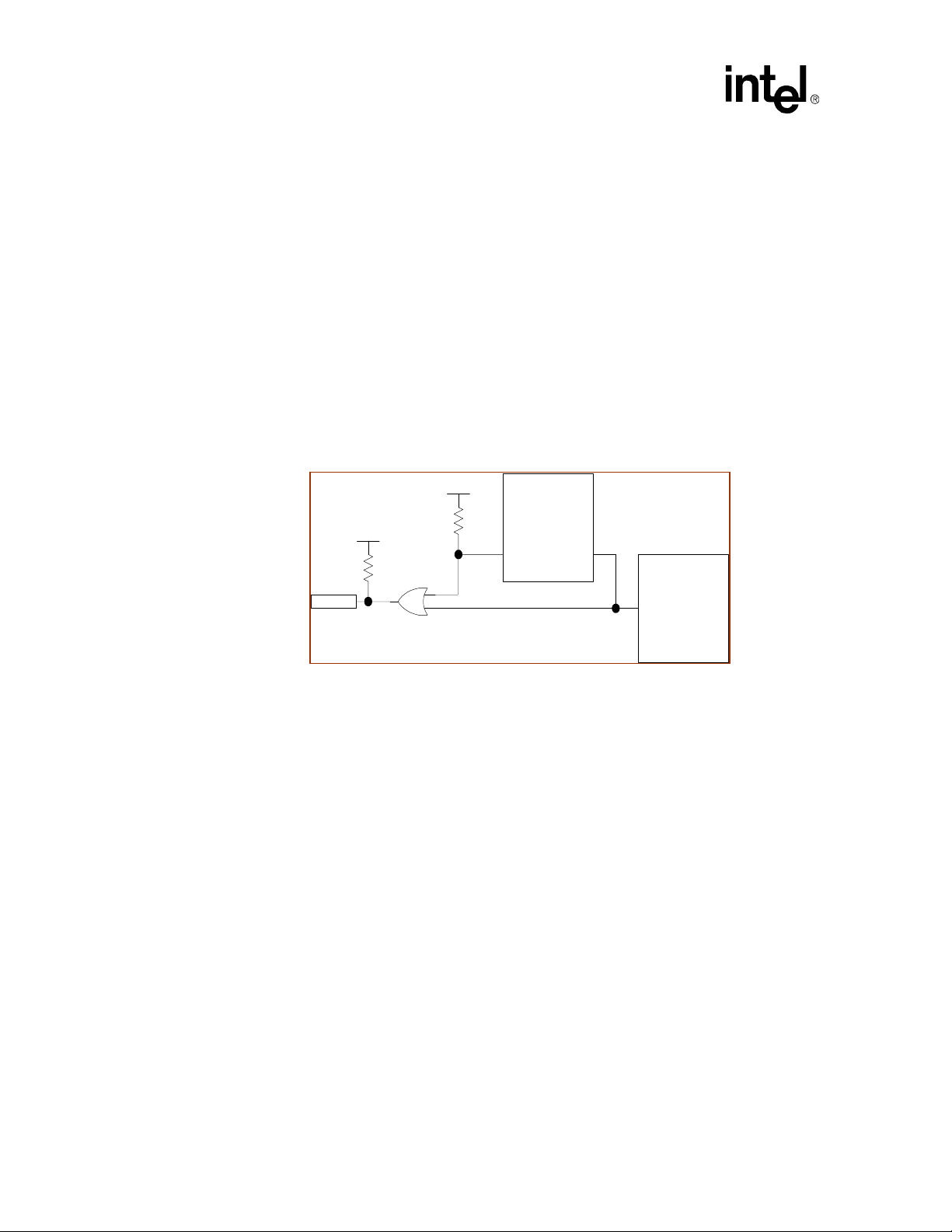
Workaround: False PME indications can be avoided by disabling the recognition of a PME before removing or
restoring power to the 82559. If a hardware solution is required, the following isolation circuit has
been proven to be effective. The circuit requires the PCI PME signal (PCI_PME#) to be isolated
from the 82559 PME signal (PME#). The system does not see the 1.5 voltage level drop caused by
the 82559’s power transition.
3.3Vaux
System Board
R1= 10k
R2 = 10k
3.3V
PCI_PME#
i
C
C
B
i
B
E
i
E
PCI
Connector
3.3V
R3 = 10k
10k
82559
PME#
82559 Stepping Information 9
Page 15
Errata
Status: There are no plans to fix this anomaly in the 82559 device.
8. Modem Interrupt Propagation
Problem: The propagation of modem interrupts in the 82559C is linked to PCI clock activity. The 82559C
local interface enables ISA based modems to operate in a PCI environment. In Advanced Configuration and Power Interface (ACPI) systems, the operating system may place the 82559 in the D3
power state and shut down the PCI clock while the modem is active. This prevents the 82559 from
clocking modem interrupts to the system.
Implication: If the Clockrun protocol is used, the PCI clock can be shut down during modem sessions. In this
case, the modem interrupt is not propagated through the 82559 to the Interrupt A pin.
Workaround: Three possible workarounds for this anomaly are listed below:
1. Disable the Clockrun signal during modem use.
2. Drive the Clockrun signal directly from the modem using external circuitry.
3. Drive the Interrupt A pin directly from the modem.
3.3v
3.3v
82559
INTA# Modem Int
Modem
Status: The 82559C is the last stepping of the 82559 device. There are no plans to fix this anomaly in the
82559.
9. Corrupted PCI Burst Read with D0 System Management Bus Receive
Problem: A race condition can occur between the marker of an incoming frame (containing its status word)
and the completion of the last receive buffer in designs that use a flexible Receive Frame Descriptor
(RFD) with more than one Receive Buffer Descriptor (RBD). This can cause false burst reads from
PCI memory if an alert packet destined for the SMB port is received while the 82559 is in the D0
power state.
Implication: The 82559 may attempt to read data from random PCI addresses and the received alert frame will
be corrupted on the SMB. This erratum is strictly limited to applications that attempt to support
both flexible RFDs and to receive SMB messages in the D0 state. (Software drivers available from
Intel are not affected by this erratum.)
Workaround: Flexible RFD should not be implemented when SMB traffic is supported in the D0 power state.The
standard simplified buffer system should be used in alert or TCO enabled systems.
Status: There are no plans to fix this problem in the 82559. (The 82559C is the last stepping of the 82559
device.)
10. Programmable Filter Corruption
Problem: The first nine Dwords of the 16 Dwords of the programmable filter storage are shared with the
transmit counters. The transmit counters are used by the 82559 if TCO frames are sent from the
10 82559 Stepping Information
Page 16

Errata
SMB in a low power state. The filters can be corrupted due to the transmit counters update process
as transmissions are completed.
Implication: Filters placed in the first nine Dwords of the programmable filters may be corrupted during TCO
transmission. Interesting packets and power management event indication signals for these filters
may not occur. This issue does not affect the standard ACPI and Advance Power Management
(APM) filters.
Workaround: If programmable filters are used, the construct of the Load Programmable Filter Command should
be structured in such a way that the first nine Dwords of the filters are dummy filters. This structure
should be followed with the next seven Dwords of real filter data.
Status: Since the 82559C is the last stepping of the 82559 device, there are no plans to fix this errata.
11. Invalid Alert Response Address (ARA) Return
Problem: When the software driver issues initialization cycles, including both port software resets and
selective resets, the 82559 may respond with an invalid SMB address (FEh or FFh) during an Alert
Response Address (ARA) cycle. This occurs since a majority of SMB operations use the parallel to
series register to save command and address information. This can cause the Selective Reset to
damage the contents of the 82559C.
Implication: This problem does not cause any issues in real systems for the following reasons:
• FEh is an invalid SMB address and not used.
• The FFh address is viewed as a no responder on the bus.
Also, the 82559 follows the ARA cycle with a valid SMB alert and ARA. Thus, data will not be
lost.
Designs using the Alert on LAN* 2 ASIC do not use ARA cycles. Therefore, this is not an issue for
these types of designs.
Workaround: Invalid addresses returned during ARA transactions should be ignored following a reset event.
Status: There are no plans to correct this errata in the 82559. (The 82559C is the last stepping for this
device.)
12. Potential Receive Overrun in Dynamic Standby Mode
This issue can affect all design implementations using the 82559 (B-step) LAN Controller.
Problem: The 82559 (B-step) supports a Dynamic Standby mode. In this mode, the 82559 powers down
certain logic blocks to save power during periods of inactivity. It automatically switches to
Dynamic Standby Mode when it is in Idle mode and Dynamic Standby mode is enabled.
In Dynamic Standby mode, a possible synchronization condition may occur preventing the device
from waking up when it receives an incoming frame. If this happens, the frame is not properly
handled and is lost.
When the 82559 (B-step) is in the Dynamic Standby mode, clock signals to the MAC are stopped.
Any received packet that passes address filtering causes the MAC block to wake up. The MAC
block wakes up in a specific timing window by synchronizing between a recovered clock and
82559 Stepping Information 11
Page 17

Errata
internal generated clock. A synchronization problem occurs between the recovered clock and
internal generated clock. This window in which the problem can occur is identified as
approximately 20 clocks at the beginning of the reception of a packet.
PHY
MAC BLOCK
BLOCK
PCI I/F
BLOCK
DMA
engine
BLOCK
CSMA
Block
Internal clock
idle
Rx
Indication
Implication: The probability of this synchronization problem occurring is low with slower material but increases
with faster material. The reason for this is assumed to be due to fabrication process variation.
When the frame rate is higher, the internal hardware stays active and does not enter Dynamic
Standby mode. Thus, overruns are not observed. When the frame rate is low, the internal hardware
may enter Dynamic Standby mode causing the problem to be observed.
Workaround: To avoid potential receive overruns, the Standby Enable bit in the EEPROM (Word 0Ah, bit 1)
should be set to 0b. This results in increased power consumption of approximately 40 mW. (A
DOS-based utility is available through your local Intel sales representative to disable the Standby
Enable bit in the EEPROM.)
Status: This anomaly has been corrected and does not exist in the 82559C.
12 82559 Stepping Information
Page 18

Errata
13. False Detection of Security ASIC
Problem: The lack of a pull down resistor on FLA[6] can enable it to float, allowing the detection of a non-
existent security ASIC.
The 82559C contains a hardware configuration mechanism allowing it to detect the presence of a
security ASIC (82594ED). The mechanism samples the Flash Address 6 (FLA[6]), pin as a
configuration input during a hardware reset cycle. If FLA[6] is sampled high, the 82559 is
configured to interface with the ASIC. In other words, the security ASIC device select pin (CFCS#)
is set and the security ASIC itself is also set.
The 82594ED security ASIC has a Present bit. The Present bit is used by the LAN device driver to
determine whether the security ASIC is present. If the ASIC is present, it drives FLA[6] high
during reset. However, if the ASIC is not populated not populated, FLA[6] may float during reset,
causing the security ASIC to be falsely detected.
In the second case, an IPSec offload-enabled LAN driver attempts to initialize the non-existent
ASIC, resulting in an improperly loaded driver.
In LAN/modem designs that use both the Flash Chip Select (FCS#) and security ASIC chip select
(CFCS#) signals, the Modem Chip Select signal will not be generated since the CFCS# signal will
operate in a mode preventing its generation. Since the Modem Chip Select signal is not generated
in this case, the modem will be non-functional.
It does not appear that a non-existent ASIC will be detected if the FLA[6] pin is loaded due to the
presence of a Flash chip on the interface. Designs that do not use a Flash component have been
observed to have a higher likelihood of a false security ASIC detection at low temperatures.
Implication: This anomaly affects 82559 designs that do not implement the use of the security ASIC, 82594ED.
Workaround: This problem can be avoided by installing a 10 KΩ pull down resistor on FLA[6]. This prevents the
pin from floating and should be implemented on all new 82559 (C-step) designs.
For LAN only designs, a LAN driver workaround can be used by setting the “Taskoffload”
parameter to 0. This prevents the driver from initializing and using the security ASIC, even if it is
(falsely) detected, and allows the driver to initialize and function properly. This parameter can be
set through the registry or with an .INF change.
At this time, there is no known software workaround for LAN/modem combination cards using
both the Flash Chip Select and CFCS# signals from the 82559 to generate the Modem Chip Select
signal.
Status: There are no plans to correct this anomaly for 82559 devices since the 82559C is the last stepping
for this device. However, it has been fixed in subsequent 10/100 Mbps generation devices such as
the 82550.
82559 Stepping Information 13
Page 19

Specification Clarifications
Specification Clarifications
1. 82559 Initialization During System Management Bus (SMB) Access
Clarification: Initialization or reset sequences occurring during the reception of packets destined for the System
Management Bus (SMB) can cause the 82559 to drop fragments. This may cause a corrupted
sequence and, depending when the reset occurred during packet reception, lost SMB fragments.
Implication: The SMB master might observe receive packets on the SMB with missing fragments in the
sequence. If a packet was received during the reset, then the first transaction to the 82559 may be
ignored. Subsequent accesses will continue to operate properly. The management controller should
verify the completion of the incoming packet stream on the SMB to insure that the full sequence is
received. The easiest method to perform this check is to verify that a SMB message was received
with first, middle, and last segment markers set in order. When the 82559 is accessed across the
SMB after a reset event, a second attempt may be required if the first access timed out.
2. 82559C Compliance
Clarification: The 82559C was designed to be fully compliant with the SMB Specification. The SMB is a
derivative of the Phillips I
in hybrid systems. The 82559C is specified to meet or exceed the SMB hold time requirements but
may interfere with devices relying on the 0 nanosecond hold time allowed under the I
cation.
Implication: Systems using I
devices reside on the same SMB as the 82559, it must be insured that no devices attempt the 0 ns
hold time.
2
C devices on the SMB may misinterpret data or address information. If other I2C
2
C* bus but does not comply with all I2C timings. Hold time may differ
2
C specifi-
3. Link Loss Deep Power-Down Noise Sensitivity
Clarification: The 82559C supports a Deep Power Down on link loss feature. This feature enables the 82559C to
shut down when cable or activity from its link partner is present. If this feature is enabled, a
powered down 82559C physical layer (PHY) unit can be turned on by excessive noise. The
thresholds on the 82559C were chosen to work with existing devices on the market, with the goal
of enabling the PHY over disabling the PHY in ambiguous situations.
Implication: The 82559C may not be able to remain in the deep power down mode in noisy environments. This
is not a serious concern because of the 82559’s general low power consumption and its ability to
shut down all but the PHY in this situation. Several changes can be made to the line interface to
limit noise. These changes are only required on the receive pair of the device. This includes adding
a capacitor between receive differential pair (RDP and RDN). Additional capacitance between the
receive pair helps filter the differential noise but may have a negative impact on the receive
performance and on receive return loss. A capacitor value above 15 pF may impact performance
and should be disconnected after link is achieved.
4. PCI Buffer Leakage When the Voltage Input/Output Pin (VIO) Not Powered
Clarification: When the system is in a suspended state (Voltage Input/Output pin equals 0 volts and power equals
3.3 volts), the 82559 PCI I/O buffers can rise to about 700 mV causing a leakage current to flow
into the Voltage Input/Output (VIO) pin. The resistor value greater than 50 KΩ is recommended in
some of the application notes relating to 82559 based designs. (61 KΩ is used in the Intel reference
design.) In 82559C designs it is recommended that the VIO pin is pulled to the 3.3 V rail used by
the device or a +5 V rail that is active when the 82559C is powered (for example, +5 V
auxiliary
).
14 82559 Stepping Information
Page 20

Specification Clarifications
Implication: The 82559C VIO pin should be active when the device is active. This provides the lowest power
consumption in suspend states.
5. Load and Start Receive Unit Commands in IP Security Applications
Clarification: When the 82559C is used in combination with a security companion ASIC, the software driver
should not issue both a Load Receive Unit (Load RU) and Receive Unit Start (RU_START)
command when sending the SU packet in the receive unit idle state. It is recommended to issue the
Load RU Base (Load RU_BASE) and Load Header Data Size (Load HDS) commands before the
first SU packet is sent in the receive unit idle state.
Implication: The implication of this issue is limited to the applications that support IP Security (IPSec) off-load
using a companion ASIC with the 82559C.
82559 Stepping Information 15
Page 21

Documentation Changes
Documentation Changes
1. 82559 LAN on Motherboard Design Guide
Document Title: Intel
Previous Revision: Revision 1.1, July 1998
Current Revision: Revision 1.2, November 1998
Changes: The application note (AP-392) was updated to reflect the new passive component values to
optimize cable performance. The changes are limited primarily to the PHY circuit area. Additional
decoupling capacitance was added in the form of two 4.7 µF capacitors placed as close to the 82559
as possible. A 0.1 µF decoupling capacitor was also added to the Voltage Input/Output (VIO) pin.
The receive line termination resistor was also increased to 120 Ω.
Impact: The changes are limited to value changes for optimizing performance. Designs implemented using
the guidelines outlined in revision 1.1 of AP-392 are fully functional with the 82559 B-step silicon.
The value changes are viewed as Bill of Materials (BOM) changes except for the additional
decoupling. The additional decoupling requirement is application specific and may not be needed.
Previous Revision: Revision 1.2, November 1998
Current Revision: Revision 1.3, September 1999
Changes: The application note (AP-392) was updated to the new recommendation for the PCI Reset signal to
be tied to the 82559C’s Isolate pin. This change was made to maintain the proper relationship
between the Isolate and Reset signals on the 82559C. It was always recommended that the Isolate
signal is not asserted following the assertion of the Reset signal and to ensure that the isolate event
precedes a reset event. This has proven to be a difficult task in actual application; therefore, the
recommendation was changed to simplify board design.
Impact: Operational designs that meet previous recommendations do not require any changes. The new
recommendations provide a simpler solution for new board designs.
®
82559 LAN on Motherboard (LOM) Design Guide Application Note (AP-392)
Current Revision: Revision 1.3, September 1999
Changes: A pull down resistor of 10 KΩ will be added to the reference schematics.
Impact: This change is limited to 82559C-based designs that do not use a security ASIC or Flash
component.
16 82559 Stepping Information
Page 22

Documentation Changes
2. Software Technical Reference Manual
Document Title: Intel
Previous Revision: Revision 1.2, November 1998
Current Revision: Revision 1.3, August 1999
Changes: Software must issue a Port Reset command following a power state transition to the D0 state from
the D1 or D2 states. This is required to clear the wake-up filters that are automatically cleared on
the normal D3 state to D0 state change.
Impact: A corruption of the PCI Direct Memory Address (DMA) in the 82559C may occur if the wake-up
filters are still active following a transition.
Changes: The Link Status Indication bit in the Power Management Driver Register (PMDR) to a reserved bit
(0).
Impact: The 82559C will still wake-up on a Link Status change, but this bit cannot be used to poll for link
status as a cause for the wake-up.
Changes: EEPROM Word Dh, bit 15 changes to a reserved bit (0).
Impact: This bit has always been defined as equal to 0 for all configurations. The change is only limited to
calling it out as reserved in this description.
®
10/100 Mbit Ethernet Family Software Technical Reference Manual
Changes: When High Priority Queue (HPQ) is used, The End of List (EL) bit is not allowed for both HPQ
and Low Priority Queue (LPQ). Software should only use the Start (S) bit to identify the end of a
Command Block List (CBL) in a HPQ.
Impact: This change does not effect existing drivers. However, drivers that add support for multiple priority
queues will be affected.
Changes: The 82559C does not support TCP format TCO frames. It only supports UDP format TCO frames
(protocol number 04h).
Impact: TCO messages for Alert on LAN* technology are defined as UDP packets.
3. 82559 Fast Ethernet Controller Datasheet
Document Title: Intel
Current Revision: Revision 2.1, March 2000 (This document will be updated to correct the following changes.)
Changes: The EEPROM Data Output (EEDO) and EEPROM Data Input (EEDI) signal definitions will be
clarified to eliminate confusion.
During EEPROM accesses, this pin accepts serial input data from the EEPROM Data Output pin.
During EEPROM accesses, this pin provides serial output data to the EEPROM Data Input pin.
Impact: This does not change the definition of these signals.
®
82559 Fast Ethernet Multifunction PCI/CardBus Controller
82559 Stepping Information 17
Page 23

Documentation Changes
Changes: Flash and modem pin descriptions should include the following text:
“If Flash and modem functionality are not used, this pin should be left floating.”
Impact: These pins should not be connected if Flash and modem are not implemented.
Changes: Section 5.1.1, “100BASE-TX Transmit Clock Generation,” contains an incorrect accuracy value
for the external crystal of ±0.0005% (50 PPM). It should read “±0.005% (50 PPM).”
Impact: This change is strictly limited to correcting the incorrect percentage value only of accuracy for the
external crystal. It does not affect the PPM value.
Changes: Table 32, “100BASE-TX Voltage/Current Characteristics,” and Table 33, “10BASE-T Voltage/
Current Characteristics,” will be updated to reflect the correct Input Differential Accept Peak
Voltage (V
) and Input Differential Reject Peak Voltage (V
IDA
IDR
).
Table 32. 100BASE-TX Voltage/Current Characteristics
Symbol Parameter Condition Min Typical Max Units Notes
V
IDA100
V
IDR100
Input Differential
Accept Peak Voltage
Input Differential
Reject Peak Voltage
5 MHz ≤ f ≤ 10 MHz ±500 mV
5 MHz ≤ f ≤ 10 MHz ±100 mV
Table 33. 10BASE-T Voltage/Current Characteristics
Symbol Parameter Condition Min Typical Max Units Notes
V
IDA10
V
IDR10
Input Differential
Accept Peak Voltage
Input Differential
Reject Peak Voltage
5 MHz ≤ f ≤ 10 MHz ±585 ±3100 mV
5 MHz ≤ f ≤ 10 MHz ±300 mV
Impact: The Input Differential Accept Peak Voltage is defined as the differential level of input voltage (for
example, absolute magnitude of difference between RDP and RDN) that is guaranteed to be
accepted as a valid input signal by the receive circuit. There is no typical value and it should not
even be specified.
The Input Differential Reject Peak Voltage is defined as the differential input voltage that is
guaranteed to be rejected as noise by the receive circuit.
Changes: The EEPROM should operate at a frequency of at least 1 MHz.
Impact: Table 42, “EEPROM Timing Parameters,” will be updated. Row T50 will be deleted, which shows
the maximum EEPROM operating frequency as 1 MHz. This is incorrect.
Changes: References to 10/100 Mbit Family Software Developer’s Manual will be changed to 10/100 Mbit
Ethernet Family Software Technical Reference Manual.
Impact: The 10/100 Mbit Family Software Developer’s Manual does not exist and was incorrectly
referenced. It should be 10/100 Mbit Ethernet Family Software Technical Reference Manual.
18 82559 Stepping Information
Page 24

Documentation Changes
Changes: The current consumption in deep power-down mode should read 6.5 mA (instead of 3 mA) to
comply with device performance.
Impact: This change is limited to the most power conscious mobile platforms.
82559 Stepping Information 19
 Loading...