

Page 1

TABLE OF CONTENTS
SECTION 1 — GENERAL INFORMATION ....................................... - 1 -
1.1 INTRODUCTION ................................................. - 1 -
1.2 BENEFITS ....................................................... - 1 -
1.3 USES ........................................................... - 2 -
1.4 PRINCIPLE OF OPERATION ....................................... - 2 -
1.5 TECHNICAL SPECIFICATIONS ..................................... - 3 -
1.6 PRECAUTIONS .................................................. - 4 -
SECTION 2 — INSTALLATION ................................................ - 5 -
2.1 SYSTEM CONFIGURATION ....................................... - 5 -
2.2 RheoVac SENTRY INSTALLATION/SITE SELECTION .................. - 5 -
2.2.1 Probe Site Selection .......................................... - 5 -
2.2.2 CPU/Distribution Box Site Selections ............................ - 6 -
2.3 HOT TAP INSTALLATION ......................................... - 7 -
2.4 PROBE INSTALLATION ........................................... - 7 -
2.5 ELECTRICAL CONNECTIONS ..................................... - 9 -
SECTION 3 — OPERATION .................................................. - 13 -
3.1 GENERAL INFORMATION ....................................... - 13 -
3.2 OUTPUT PARAMETERS ......................................... - 13 -
3.3 RheoVac SENTRY PROBES ........................................ - 13 -
3.4 CPU TOUCH SCREEN ............................................ - 14 -
3.5 ETHERNET or MODEM OUTPUT .................................. - 18 -
3.6 SEARCHING FOR LEAKS WITH MULTI-PROBE SYSTEM ............ - 20 -
SECTION 4 — MAINTENANCE ............................................... - 22 -
4.1 GENERAL MAINTENANCE ....................................... - 22 -
4.2 CALIBRATION .................................................. - 22 -
4.3 SPARE PARTS .................................................. - 22 -
4.4 TROUBLE SHOOTING ........................................... - 22 -
SECTION 5 — CUSTOMER SERVICE ......................................... - 24 -
5.1 QUESTION ON EXISTING HARDWARE ............................ - 24 -
5.2 TROUBLE SHOOTING ........................................... - 24 -
5.3 FACTORY AND FIELD SERVICE .................................. - 24 -
5.4 QUESTIONS ON NEW EQUIPMENT ................................ - 24 -
SECTION 6 — CUSTOM INFORMATION ...................................... - 25 -
6.1 UNIT IDENTIFICATION .......................................... - 25 -
6.2 CONFIGURATION ............................................... - 25 -
6.3 SPECIAL INSTRUCTIONS ........................................ - 25 -
©Intek, Inc. 2004
I:\OFFICE\WPMAN UAL\SENTRY\RVSentryRev. A.wpd
Manual no. RVSentry Rev. A
Page 2

WARRANTY
Intek, Inc. warrants each RheoVac® product to be free from defects in
material and workmanship under normal use and service, Intek's
obligation under this warranty being limited to making good any part or
parts thereof which shall, within one (1) year after delivery of such
product to the original purchaser, be returned to Intek with transportation
charges prepaid and which Intek's examination shall disclose to its
satisfaction to have been thus defective; this warranty being expressly in
lieu of all other warranties, express or implied and all other obligation or
liabilities on Intek's part. The purchaser will assume all responsibility
and expense for removal, decontamination and reinstallation of
equipment.
Intek’s instruments are manufactured under United States patent numbers
4,255,968, 4,942,763, 4,949,578, 5,445,018 5,485,754 and 5,752,411. Intek,
Rheotherm, Rheovec, Rheomax, RheoVac and RheoSmart are registered
trademarks of Intek, Inc.
Intek, Inc.
751 Intek Way
Westerville, Ohio 43082-9057
Phone (614) 895-0301 – Fax (614) 895-0319
web site – www.intekflow.com
e-mail – techsupport@intekflow.com
Page 3

SECTION 1 — GENERAL INFORMATION
1.1 INTRODUCTION
In 1994, Intek Inc. introduced the RheoVac® air in-leak monitor for continuously measuring condenser
air in-leakage. This monitor was the first and only instrument to measure all of the necessary fluid
properties in the condenser exhaust line to provide an accurate, reliable air in-leakage measurement:
— the RheoVac
®
Air In-Leak Monitor*
*USPNs 5,485,754; 5,752,411
The next generation instrument, the RheoVac SENTRY, uses the same proven sensor configuration, but
brings new capabilities consistent with the industry’s need for local as well as centralized and remote
monitoring.
The RheoVac technology was developed with the help of power plant engineers, to overcome the
deficiencies of existing air in-leakage and condenser performance measurement instrumentation and to
create a powerful, complete condenser system analysis tool. No single product provides power plant
engineers with as much diagnostic information related to the condenser as the RheoVac SENTRY System.
In addition to providing reliable, real time indication of condenser air in-leakage, the SENTRY System
provides valuable information that can be used to analyze problems associated with vacuum system
components, thereby improving plant efficiency, reducing downtime and increasing maintenance
effectiveness.
1.2 BENEFITS
The following are some of the unique benefits of the RheoVac SENTRY System:
• Distinguishes between air flow and water vapor flow
• Measures exhauster capacity
• Measures vacuum quality
• Allows operators to distinguish between air in-leakage and pump failure
• Continuous monitoring provides event time stamp
• Provides high resolution, range and accuracy of data
• Retrievable on-board data storage
• Provides data for condenser performance diagnostics
• Provides centralized access to the data from all of the RheoVac probes installed in the system
• Provides easy access to individual probe’s data as well as on-screen review of selected
common data from all of the probes for performance analysis
• Graphic representation of monitored data gives visual indications of performance changes
• Provides easy review of “before” and “after” data through the diagnostics screen to evaluate
the effect of system changes
• Portable remote measurement (optional feature) of air-in-leak changes through the use of a
hand-held display unit – used to locate leaks
- 1 -
Page 4

1.3 USES
The RheoVac SENTRY System can be used for a multitude of performance related subjects, such as:
• Continuous air in-leak monitoring
• Vacuum pump performance testing
• Operating with zero excess back pressure
• Load dependent air in-leak isolation
• Optimizing condenser performance
• Scheduled preventive maintenance
• Leak detection during hogging operation
• Minimizing heat rate
• Optimizing condensate/water chemistry
• Understanding condenser performance
1.4 PRINCIPLE OF OPERATION
The RheoVac technology utilizes multiple primary sensors configured in a single probe head and an
electronic signal conditioner and digital signal processor unit. The sensing probe is installed in the
vacuum line between the condenser and the exhauster. The RheoVac instrument makes no assumptions
about the dynamic condenser and vacuum line environment. The sensor head employs the patented
Rheotherm® technology to provide an accurate flow measurement. Additionally, temperature, pressure
and water vapor relative saturation measurements are made using a high accuracy platinum resistance
temperature detector (RTD), a strain gauge pressure sensor and a specially configured and calibrated
water vapor saturation sensor. The principal features of the RheoVac sensor are shown in Figure 1.
Figure 1 RheoVac Probe Sensor Monitor
- 2 -
Page 5

At the heart of the RheoVac probe is the Rheotherm flow transducer, which uses the same patented
thermal sensing technique employed in all precision flow instruments manufactured by Intek. Two
temperature sensors are used; one sensor is in thermal equilibrium with the flow medium and provides
a temperature and flow signal reference, while the second sensor is located near a constant power heater
so that its temperature is always above that of the fluid. The temperature of the heated sensor will vary
with the stream velocity of the fluid. Hence, the measured temperature differential between the reference
sensor and heated sensor is a function of flow rate, which is approximately proportional to the logarithm
of mass flow rate (USPN 4,255,968).
The Rheotherm flow sensor is calibrated to measure the total mass flow of the water vapor/air mixture.
From the other three measurements, the RheoVac SENTRY electronics converts the total mass flow
signal from the probe into two components, air mass flow rate and water vapor mass flow rate. This
unique measurement method is disclosed in two separate patents (USPN 5,485,754 & 5,752,411). The
RheoVac probe is fully calibrated at the factory under dynamic fluid conditions identical to those within
the power plant vacuum line. No field adjustments are required.
In the RheoVac SENTRY System, multiple RheoVac probes are installed at pre-determined condenser
vacuum line locations to provide the most appropriate measurement data for the condenser system.
Depending on the plant configuration, sometimes a single SENTRY System can be configured to monitor
more than one generating unit. The probes are connected to the SENTRY CPU, which processes the
measured data and provides the system output data. The SENTRY System, in add ition to data processing,
display and graphing, also communicates the data, through 10Base-T Ethernet, to the plant control room,
engineer’s office, and/or Intek via modem or internet.
1.5 TECHNICAL SPECIFICATIONS
Primary Calibration Accuracy:
±1% of reading
Repeatability:
±0.5% of reading
Operating Temperature:
Electronics: 32 to 100°F
Probe: 40 to 160°F
Never subject probe to
temperatures above 210°F
Operating Pressure:
0 to 10 inches Hg absolute
Process Connection:
Hot tap assembly
(1½” thread-o-let must be welded to
pipe for hot tap installation)
Wetted Surface:
300 Series SS and engineering plastic
NEVER allow RheoVac probe heads to
be immersed in liquid water or be
exposed to live steam
Local Display:
touch screen display of all parameters
from each probe, with graphing capability
Input Power:
115 Vac, 50/60 Hz (+10%/!20%)
Signal Output:
Ethernet (10Base T) RJ45
4-20mA (optional)
Storage Temperature:
!20 to 120°F
Storage Pressure:
15 psig (maximum)
Maximum number of probes/SENTRY CPU: 12
- 3 -
Page 6

1.6 PRECAUTIONS
• Read the entire manual before installing and operating the RheoVac probes and SENTRY
System.
• Carefully select the best location for installation of the sensing probe. Adequate straight run
and freedom from standing water in the line are vital to achieving optimal performance from
the RheoVac system (See Figure 2).
• Use reasonable care in handling the sensing probe(s) — the sensing components are delicate.
Take care not to bend the probes, damage the tips, or otherwise obstruct the sensing ports.
When a probe is taken out of line, always place it in the protective sheath which is shipped
with probes from the factory.
• Use proper input power.
• Check the probe maximum temperature and pressure ratings — never operate a probe at or
subject it to temperatures or pressures beyond its specified limits.
• Keep moisture out of the enclosures — once all service connections are made, make sure the
enclosure lids are tightly closed and all gaskets are in place. Seal conduit lines at the
instrument.
. . WARNING . .
1. Never allow live high temperature steam to flow in either direction in the
exhauster line where the probe is located.
2. Never flood an exhauster line that has a RheoVac probe in it. Always remove
the probe, or seal off that section of pipe before a hydrostatic leak test is
performed.
- 4 -
Page 7

SECTION 2 — INSTALLATION
2.1 SYSTEM CONFIGURATION
The system provided consists of:
• a RheoVac SENTRY central processing unit (CPU) in a metal housing. The CPU includes a
touch screen interface, uninterruptible power supply (UPS), modem (optional),
interconnections and controls
• up to twelve (12) RheoVac SENTRY probes (see Custom Information Section)
• one (1) or more distribution box(s), and remote power supply boxes as required, (see Custom
Information Section)
• RS485 cable for connecting the probes and electronics boxes.
A drawing is included in this manual illustrating the general layout of all the SENTRY components.
2.2 RheoVac SENTRY INSTALLATION/SITE SELECTION
2.2.1 Probe Site Selection (IMPORTANT)
# Select the installation site. The location should provide the probe’s sensing area with well-
established smooth flow, uniform system temperature and pressure, and consistent non-liquid
phase flow medium. Refer to Figure 2 and select the most preferred location that fits your
vacuum line configuration.
# DO NOT INSTALL THE PROBE DOWNSTREAM OF ANY “TRAP” SECTIONS AS
SHOWN IN FIGURE 2, CONFIGURATIONS B AND D. Special installation instructions
unique to your unit, where applicable, will be noted in SECTION 6.3 SPECIAL
INSTRUCTIONS. Refer to this section now to review any special instructions.
# Check installation clearance. The probe is almost 3 feet long and the hot tap assembly is about
13” long, so allow 4 feet of clearance for probe installation. Be sure there are no obstructions
around the vacuum line that will interfere with probe insertion or removal and that there is
sufficient room for flexible conduit.
# OBSERVE the selected site. It should be convenient for removal and replacement of probe(s)
at any time for service without building scaffolding or waiting for plant shutdown.
# Figure 3 shows the proper insertion angle. THIS ORIENTATION IS IMPORTANT FOR
PROPER OPERATION.
# Check operating conditions. The temperature and pressure limits of the unit should be checked
to ensure compatibility with your installation point, see Section 1.5.
- 5 -
Page 8
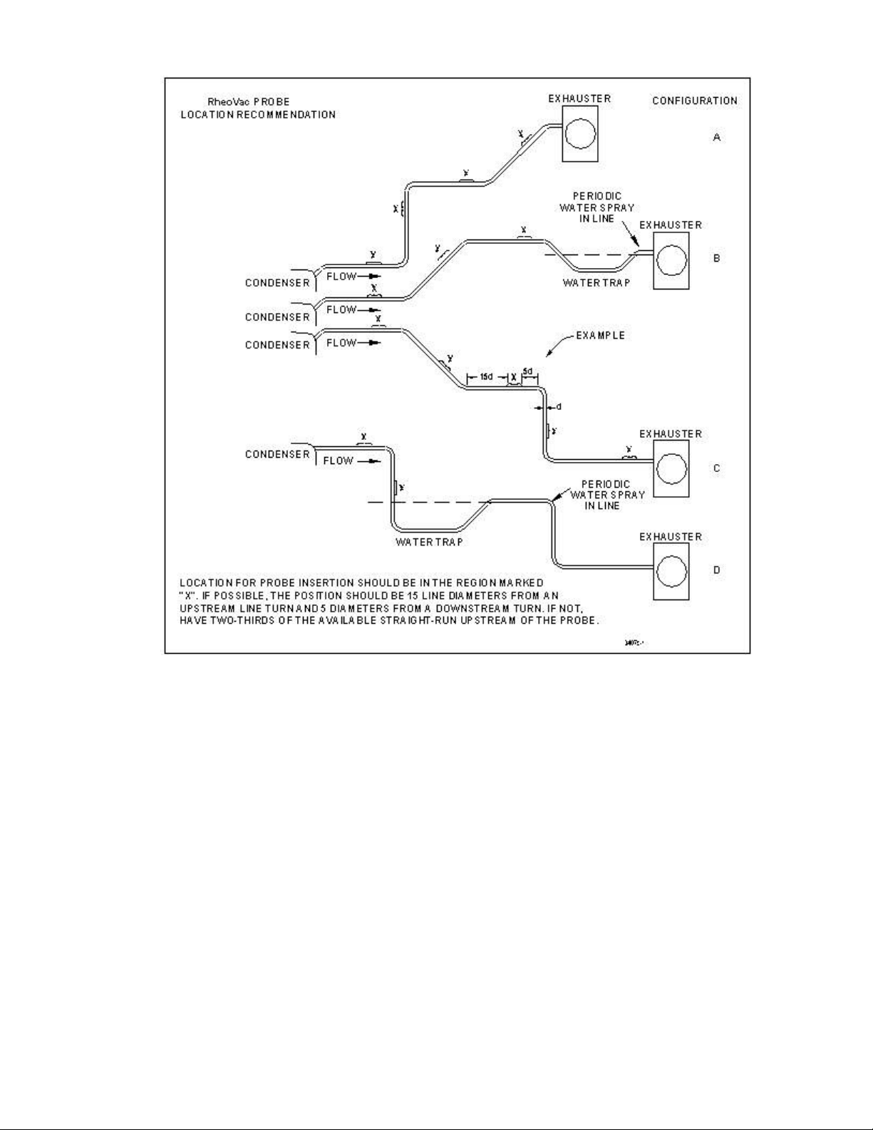
Figure 2 RheoVac Probe Insertion Recommendation
2.2.2 CPU/Distribution Box Site Selections
# Select the CPU installation sit e. The CPU should be located in a cool, dry area. The
electronics are not protected against condensed liquid water inside the enclosure. The location
should permit easy viewing and access to the touch screen display. Maximum temperature in
the area should not exceed 100°F.
# Check for input voltage access. The electronics unit should be located in an area with access
to a 115 Vac single phase, 50-60 Hz input power source.
# Consider the distances to all of the distribution boxes (located near the probes). Distances of
250 feet or more away from CPU may require a remote power supply (depends on number of
probes).
# Distribution boxes are used to split off the RS485 signal to the probes. Distances from the
distribution boxes to the probe, or probes, should be kept to 15 feet or less, if possible. Cable
runs between distribution boxes can be hundreds of feet, although a remote power supply
might be needed.
- 6 -
Page 9
These instructions cover installation of the RheoVac probes and SENTRY CPU in its standard
configuration. Additional information pertaining to your unit is covered in SECTION 6 — CUSTOM
INFORMATION. Carefully read these instructions prior to installing the equipment.
2.3 HOT TAP INSTALLATION
Î Check installation configuration. Make sure the probe is parallel to the floor (see Figure 4).
Ï Check installation clearance. Verify there is a minimum probe insertion clearance of 4 feet
from the pipe surface.
Ð Install the mounting hardware. Drill a 1½” through hole and weld the thread-o-let onto the
condenser vacuum pipe (See Figure 4). Thread the hot-tap assembly into the thread-o-let. Use
thread tape or pipe dope to seal the connection.
Ñ It should be convenient to apply a restrictive or pulling force of between 9 and 11 lbs to
remove or replace the probes under plant operating conditions.
2.4 PROBE INSTALLATION
Î Check proper installation direction. The probe has a directional arrow on the tag and/or etched
into a metal part. Before installing the unit, note proper flow direction. This is important to
instrument operation.
Ï Check serial number of the probe. Choose a location for each probe (always reinstall probe
to same location). Custom labeling of the SENTRY screen with probe serial numbers or other
I.D. is possible - see Section 3.3.
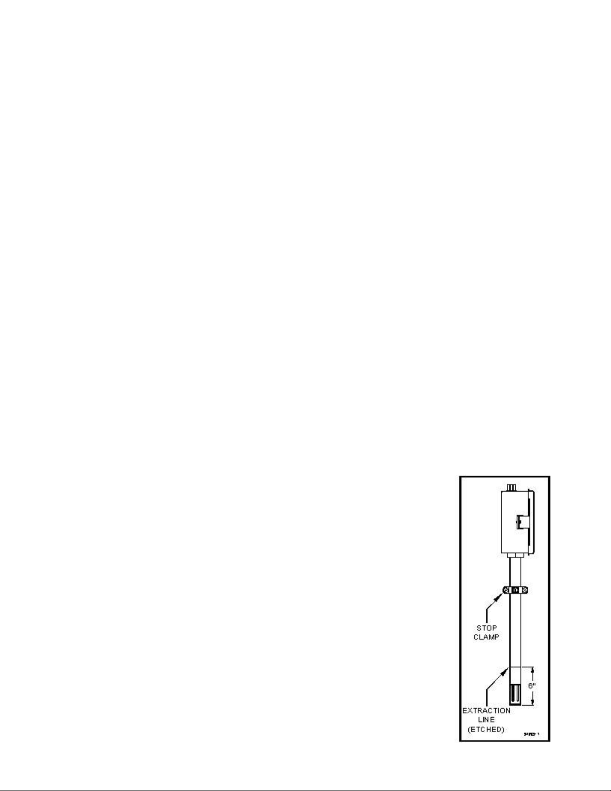
Ð Verify stop clamp location (see Figure 3). A stop clamp is attached to each probe as an
indication of its insertion depth. It is important this stay in place in
order for the probe to be installed correctly and to ensure the end of
the probe does not contact the opposing pipe wall. The clamp’s
location is determined based on the diameter of each pipe, as shown
in SECTION 6.2, and is marked with a groove on the probe’s shaft.
Refer to this mark if the stop clamp is inadvertently moved.
Ñ Inspect the probe tips. Be sure wetted surfaces are clean before
installing. If cleaning is needed, use a damp cloth wetted with alcohol
and wipe dry using a soft, lint-free cloth. Do not immerse probe in
liquid alcohol or any other liquids.
Ò Install the probes. Each probe should be mounted through the pipe
wall using a hot-tap assembly. The probe installs so that the two probe
tips (visible in the probe head) are side-by-side across the gas stream.
The probe has a flow directional arrow on the tag. When installing
under vacuum, do not allow the clamp to "slam" against the seal nut
upon opening the valve. Grasp the probe shaft firmly before opening
the ball valve. Allow the probe to slide through the valve by
controlling the amount of grip on its shaft. Special installation
instructions, if any, will be noted in SECTION 6.
- 7 -
Figure 3 Transducer
Stop Clamp
Page 10

- 8 -
Probe Installation Detail
Page 11

2.5 ELECTRICAL CONNECTIONS (Make all hardware & plug-in connections with power off)
A. Distribution Box
1. Contents
a. Connection point for the RS485 wires (Blue and White), +24vdc power (Red), ground
(Black), and shield.
b. Connection point for the input from and output to other distribution enclosures.
c. Connection points for up to four devices (probes or transmitters).
d. Power "on" LED.
2. Connections
a. Mount the probe distribution enclosure(s) centrally among the devices for which it is
supplying power and communications.
b. Install ¾” liquid-tight flexible conduit between the distribution enclosure and the
probes unless ¾ rigid conduit is used for long distance runs.
c. The probe connector has an adapter, which allows the attachment of the ¾" flexible
conduit connector.
d. Connect the probes to the distribution enclosure using the manufacturer supplied four
conductor shielded cable. Probe cable connections are shown in Figure 5.
e. A termination resistor is required in the last distribution box (farthest point out from
CPU). This resistor is accessed via a jumper at JP7 in the last distribution box. The
jumper should be set on "EN” on JP7 to enable that resistor.
.IMPORTANT . Inspect and VERIFY these connections carefully. Improper connection
could damage the RS485 IC in the probe assembly as well as the other probes.
- 9 -
Page 12

B. Electronics Unit (CPU) (See Figure 6)
1. Sensor Power and Communication Line
cable, which connects the first distribution enclosure to the CPU.
2. Main Power
circuit. An external disconnect switch should be used for disconnecting power to the
system. (There is an internal circuit breaker located behind the display panel, but it is not
easily turned off in the event of a problem.) The Uninterruptible Power Supply (UPS)
in the CPU housing will continue to supply 120Vac power to the computer until the
battery runs out of power or its main switch is turned off. The CPU will "beep" if main
power is off. However, the UPS does not supply power to the probes, so disconnecting
system power will turn off all probes.
3. Modem: (If supplied)
which has a transient protected RJ11 jack. DO NOT CONNECT DIRECTLY INTO THE
MODEM.
4. LAN Connection
connection is via an RJ45 plug using CAT 5 straight Ethernet high noise immune cable
installed from the customer’s LAN system to the SENTRY CPU.
C Initial Power Up
1. Verify power connections to prevent damage to the electronics in the probes.
a. Prior to powering up the system for the first time, remove the connector from each
probe.
b. Leave the UPS power off. Apply power only to the 24Vdc power supply inside of
the CPU (See Figure 6).
c. Verify voltage at each disconnected probe for PIN 2 (red) = (+24) and PIN 3 (black)
= (Comm). If proper voltage is not at the connector, recheck wiring back through
distribution box to the CPU.
d. Turn off all power.
e. Install each connector at the probe head, then at each distribution box.
2. Power Up
a. Turn on the probe 24 Vdc power supply.
b. Check each probe, one at a time, to see if they are working (power LED "on")
c. Turn on the UPS.
d. The SENTRY computer will then power up, going directly into the SENTRY Program.
: Connect main power terminals to a dedicated 120Vac, single phase, 15 amp
A telephone modem connection is provided at the rear of the UPS,
: A LAN may be connected to the rear of the touch screen display. This
: Connect the RS485 Communications/Power
The SENTRY program will check for all the probes that are connected to it and list any that are missing
(not being seen by SENTRY CPU). If any are missing, there is probably a wiring problem. Turn off the
probe power supply and check the missing probe’s wiring connections.
- 10 -
Page 13
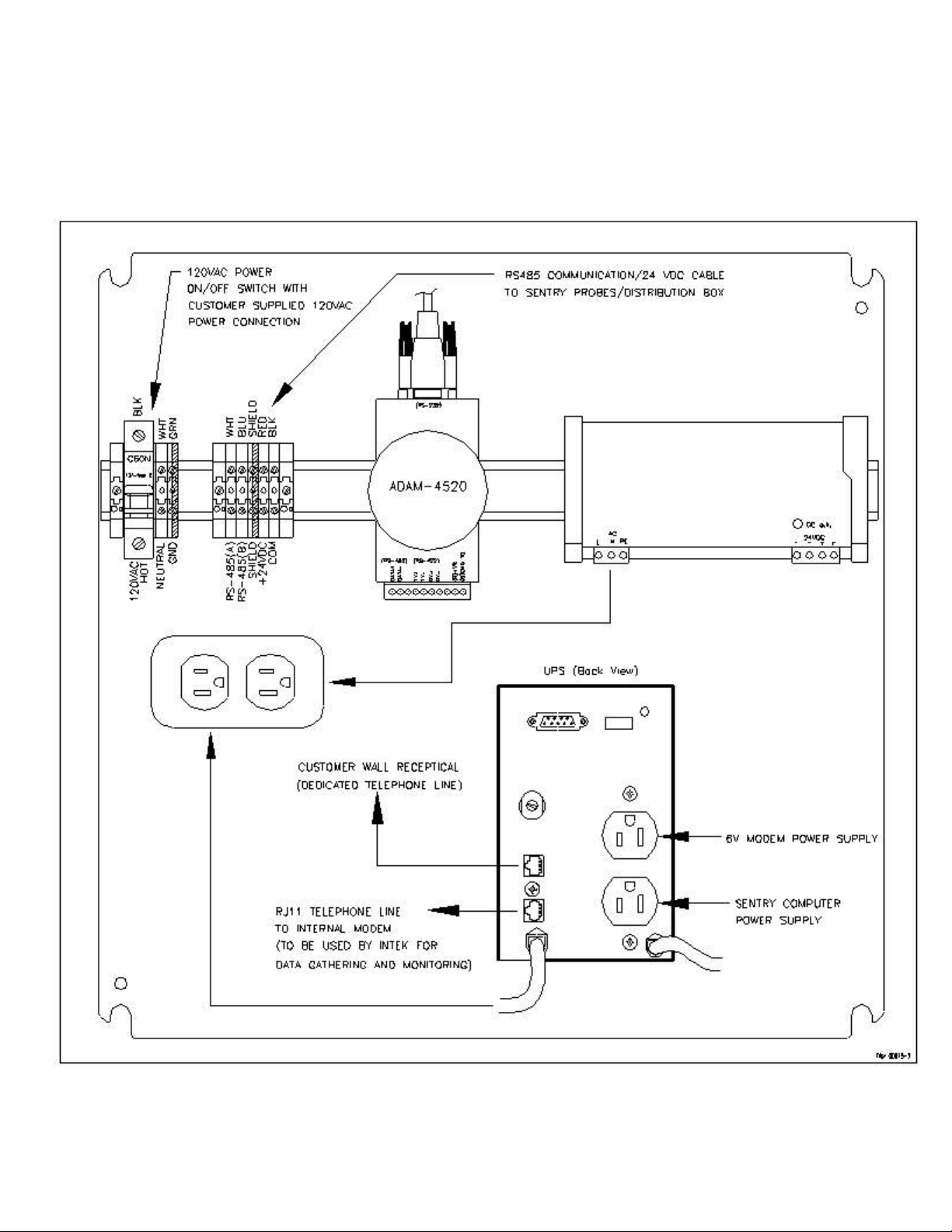
Figure 6 CPU Wiring - Part 1
- 11 -
Page 14

Figure 7 CPU Wiring - Part 2
- 12 -
Page 15

SECTION 3 — OPERATION
3.1 GENERAL INFORMATION
The RheoVac probe outputs are compensated and linearized for a wide ra nge of flowing media
temperatures, pressures, and water vapor contents. However, abrupt changes in these parameters can
cause the ins tru ment to temporarily read the flow rate improperly, which could lead to transient spikes
in the flow indication. In particular, if liquid (water) hits the probe tips, there will be high flow
indications until all the water vaporizes. This is a rare occurrence that should not happen if the probe
is properly installed per instructions in SECTION 2 — INSTALLATION.
3.2 OUTPUT PARAMETERS
The RheoVac SENTRY System measures and calculates ten output parameters. These are accessible on
the touch screen display, through ethernet, or modem connection. These output parameters are:
Table I - Output Parameters
PROCESS VARIABLE PROCESS VARIABLE DEFINITION
ACTUAL VOLUME FLOW
[ACFM]
TOTAL MASS FLOW
[lbs/hr]
WATER VAPOR MASS FLOW
[lbs/hr]
RheoVac PRESSURE
[" Hg]
WATER VAPOR SPECIFIC
VOLUME [cu. ft/lb]
WATER to AIR MASS RATIO Ratio of water vapor flow rate to dry air flow rate. Defines “vacuum quality.”
RELATIVE SATURATION
[%]
PARTIAL PRESSURE,
WATER ["Hg]
AIR IN-LEAK
[SCFM]
RheoVac TEMPERATURE
[°F]
The actual volumetric flow rate of gases leaving the condenser. It is a measure of
pump capacity. Decreased capacity means pump degradation.
The total mass flow rate of the flowing gas. Note: this value is not a measure of air inleak. It is a measure of steam jet air ejector capacity.
The water vapor component of the flowing gas being removed from the condenser.
Absolute pressure at the RheoVac probe head. Should be equal to or less than turbine
back pressure.
The inverse density of the water vapor present in the line.
The percent concentration of water vapor in the extraction line relative to saturation.
The partial pressure of water vapor in the vacuum line.
Actual measure of air volume flow rate passing the RheoVac sensor head, normalized to
standard conditions (70°F, 29.9" HgA).
Temperature of the flow media at the RheoVac probe head.
3.3 RheoVac SENTRY PROBES
In the RheoVac SENTRY System, multiple probes are installed in strategic locations of the condenser
system. Sometimes the locations will be labeled on the screen by Intek during manufacture or by the
customer after installation. As the SENTRY CPU only recognizes the probe’s identity (via its unique
serial number), and does not recognize physical locations, it is important that the assigned location for
- 13 -
Page 16

a given probe remain unchanged. To custom label the SENTRY screen with actual probe locations, you
will need to plug a PS-2 style computer keyboard into the back of the SENTRY touchscreen. After
plugging in the keyboard, reboot the SENTRY (cycle power off, then on). Press the button labeled
‘Recal/Repair’ on the RheoVac SENTRY front panel. When the Recal/Repair options panel appears,
press the button labeled ‘Probe Labels.’ The Probe Location/Information panel will appear. A space
is provided for an eight-character description to be added to each probe label (this eight-character limit
is set due to space constraints on the SENTRY front panel). After you have input your custom labels,
press the Save button. Changes will take effect when you exit back to the front panel.
Complete evaluation of a typical condenser and exhauster system is accomplished using a multiple probe
RheoVac SENTRY configuration. A multi-probe installation provides centralized data collection for all
flow paths in the air extraction system, which will aid in locating leaks and identifying exhauster
malfunction. Each SENTRY CPU is capable of supporting up to twelve RheoVac probes. Therefore, it
is possible that the configuration chosen for your plant may have the SENTRY CPU monitoring probes
installed on more than one generating unit. Accordingly, it is imperative that the serial number of the
probes and their installed locations, as shown on the original factory configuration, be clearly retained
and readily accessible.
3.4 CPU TOUCH SCREEN
The RheoVac SENTRY System CPU touch screen provides operator access, interface and control of the
components of the system. This section discusses the data and diagnostic information available to
engineers and operators via this touch screen.
Main Screen — System Diagram
The CPU main screen will show a general layout of your SENTRY System. The drawing here is a
generic example. Touching a probe “button” or icon brings up the display screen associated with that
probe. The light at the lower left of the screen indicates communication status — when data is
transmitting, the light flashes red; when no data is being transmitted, the light is a steady green. At the
bottom of the screen are the
“buttons” that provide
access to the next level of
data detail. These buttons
access the Plot, Diagnostic
Tool, Disk Info,
Recal/Repair, and Errors
functions. The
Recal/Repair function is
not used in the field except
as described above.
The STOP button should
only be used to stop
program execution and all
communications with the
probes. This is necessary
only for factory personnel to
perform software updates
and system service.
Figure 8 - System Diagram
- 14 -
Page 17

Probe Data
To view the data monitored by the RheoVac SENTRY probes, select the appropriate probe icon on the
main touch screen display. This brings up the following data screen:
Figure 9 - Ten Parameter Probe Display in Meter/Gauge Format
The data from all ten parameters monitored by the probe is updated continuously. From this screen, one
can check the same parameters from each probe by selecting another probe serial number in the “Probe
Selected” field. This screen is also used to change the pipe size setting for each probe. Always make
sure the pipe size setting is correct for any probe being monitored.
Plot
The ‘Plot’ button brings up the strip chart display of all data monitored by the probes. The information
is arranged so that the user selects a variable, such as ‘Air In-Leak,’ or ‘Temperature’ (see bottom left
for parameter selection), and the data for that parameter from all the probes in the system will be
displayed. The data is shown as a graph in the top half of the screen, and in measured values in the
bottom half of the screen. The data is color keyed for each probe.
For the graph display, the y-axis minimum and maximum values are controlled by the buttons on the left
side of the chart. Pressing the ‘Y-max’ or ‘Y-min’ button will bring up a keypad, which is used to enter
the desired value. If ‘auto’ is pressed, the display will select Y-axis values based on the data values
being graphed. The x-axis range can be similarly controlled by the dials below the plot or by the predefined increment buttons situated between these two dials. The slide bar below the chart is used to
control what point on the chart is displayed in the boxes at the bottom part of the screen. If the slide bar
is set in the far right position, as is shown, the most recent data will be displayed.
- 15 -
Page 18

Figure 10 - Plot or Strip Chart Screen
Diagnostic Tool
The ‘Diagnostic Tool’ button leads to the display screen shown in Figure 11.
Figure 11 - Diagnostic Screen
While this illustrative display only shows the data for two probes, the actual screen will show the data
from all probes in the SENTRY System. The data for each probe is displayed on two lines – the top line,
- 16 -
Page 19

with the probe serial number, is always the current set of measured data for that probe. The bottom line
of the data pair, whose button shows UPDATE or HOLD at the left side, can be user selected and placed
on ‘HOLD’ to capture the measurements of a given moment (or set of system conditions.) This is a most
unique capability of the RheoVac SENTRY System, allowing the engineer/operator to capture a “before”
set of measured parameters and then evaluate the monitored parameters “after” a known set of operating
conditions have changed. For example, when one of two exhausters is taken down for maintenance;
capture data by placing the second data line on HOLD before the exhauster removal. The live data after
removing the exhauster (the top line) can be compared to the held data to quantify the change.
Disk Info
Selection of the ‘Disk Info’ button on the main screen
brings up the screen shown in Figure 12. This screen
shows how much space is used by the data stored in the
CPU, and the amount of free space available for storing
additional data on the system’s hard drive.
Generally, it will not be necessary to remove stored system
data to archive files in order to make room on the hard
drive. Viewing this information aids the plant in
determining a suitable archive schedule.
Recal/Repair
This selection on the main RheoVac SENTRY screen is
mostly used by Intek factory service representatives.
Errors
The ‘Errors’ button on the main screen will flash if there are current, unresolved errors detected by the
system. Pressing this button brings up two error screens so that the nature of the error can be seen:
The detected error is identified
by a red light in the display
panel shown in Figure 13. The
light will indicate the nature of
the error and the probe which is
affected. The table of error
messages, shown in Figure 14,
provides a historical log of all
error messages detected, with
the latest error shown at the
bottom of the list. This log
provides the operator a clear
description of the error noted
and the date and time of the
error for resolution. See Section
on Trouble Shooting Guide.
Figure 12 - Data Storage availability
Figure 13
- 17 -
Page 20

Figure 14
3.5 ETHERNET or MODEM OUTPUT
The RheoVac SENTRY data and stored files are accessed via an Ethernet (10Base-T) connection. The
connection is made through an RJ45 port, shown in Figure 7. The line is brought into the SENTRY box
through conduit hubs in the bottom of the enclosure.
Historical data files for each probe in the RheoVac SENTRY System are stored on the hard drive of the
SENTRY CPU. A directory for each probe serial number is created in the directory named:
C:\RheoVac\data
Each file contains 24 hours of data and is named for the date on which the data was gathered. For
example, data gathered on September 14, 2000 by a probe with the serial number 99261-5 would be
located by using the file path:
C:\RheoVac\data\99261-5\091400.dat.
Note that the filename will always be six characters plus the file extension. Two digits each are used
for the month, day, and year. If you are accessing the data files from a remote location via Ethernet or
modem connection, the above file path would be modified to the fol lowing:
\\computer_name\c\RheoVac\data\99261-5\091400.dat
where "computer_name” is the Network Identification of the SENTRY CPU on your network. Each data
file is arranged in tab-delimited spreadsheet format, which can be viewed using any common spreadsheet
software application.
RheoVac SENTRY data is made available to all computers on the same network as the SENTRY CPU via
Network Dynamic Data Exchange (NetDDE). Any program running on the network that can act as a
NetDDE client, such as Microsoft Excel, can access RheoVac SENTRY data. By using this method,
SENTRY data can be accessed directly using the Plant Information Network.
- 18 -
Page 21

Data available under NetDDE includes Probe Serial Number, Time Stamp, Air In-leak, Total Mass Flow,
Water Vapor Flow, Pressure, Water Partial Pressure, Actual Volume Flow, Relative Saturation, Water
Vapor Specific Volume, Water/Air Mass Ratio, and Temperature.
This data is arranged in a table as shown in Figure 15 so that the NetDDE client can request information
from each cell of the table using the provided NetDDE Service Name, Topic Name, and the
corresponding row and column as the NetDDE Item Name.
Figure 15 - NetDDE Available Data
- 19 -
Page 22

3.6 SEARCHING FOR LEAKS WITH MULTI-PROBE SYSTEM
The next figure shows typical recommended installation locations for probes in a condenser system
where five probes are desirable and for hands free remote condenser system diagnostics. The location
for each of the five probes is identified by a number which is used in the subsequent discussions with
respect to identifying performance information.
Figure 16 - A RheoVac SENTRY System Configuration
As examples of the performance data provided by the RheoVac probe, note that it measures the flow rate
into
the vacuum pump (or air ejector) and distinguishes between air flow and water vapor flow, making
it possible to quantify the performance of the condenser’s exhausting equipment. A measurement at the
pump (or air ejector) discharge cannot provide this information.
Additionally, the RheoVac system provides recordable, real-time air in-leak measurements and will
respond to changes of air in-leak flow within 1 minute. Therefore, it can be used to quantify each source
of air in-leakage as repairs are made.
Examination of the measured air in-leak data from the installed probes will provide information on the
likely location(s) of the leaks which give rise to the measured air in-leak values. The following chart
shows indications that can be expected for the locations of different leaks. This table is prepared based
on a five-probe installation, as shown in the figure above.
Leak Location Probe Indications of Air In-Leak (SCFM) and Plant DO
Below water line, left side of
condenser
Much higher than normal DO,
1 > 2,
1 + 2 = 3 = 4 + 5,
4 = 5 This implies pumps are working identically.
Above water line, right side of
condenser
Slightly higher or normal DO,
2 > 1,
1 + 2 = 3 = 4 + 5,
4 = 5 (Identically working pumps)
- 20 -
Page 23

Leak Location Probe Indications of Air In-Leak (SCFM) and Plant DO
Small leak or faulty exhauster
down stream of probe 4
Large leak or failed exhauster
down stream of probe 4
Center joint seal, LP bearing seal,
or other central location
Slightly higher or normal DO
1 = 2,
1 + 2 = 3 = 4 + 5,
4 < 5
Slightly higher or normal DO
1 = 2,
1 + 2 = 3 = 4 + 5,
5 < 4 (Back flow at 4)
Slightly higher or normal DO
1 = 2,
1 + 2 = 3 = 4 + 5
Some examples of observed RheoVac monitor measured data and corresponding identification of leak
presence and leak location determinations are:
Leak Location Probe Indications of Air In-Leak (SCFM)
Normal tight system 1 = 2.5 SCFM
2 = 2.5 SCFM
3 = 5 SCFM
4 = 0 SCFM (exhauster 2 not in service)
5 = 5 SCFM
Abnormal, need to locate and fix
leaks (central joint seal)
Abnormal, need to locate leaks and
fix Nash pump shaft seal in
exhauster 2
Abnormal, Nash pump shaft
seal leaks in exhauster 2, but
not totally failed
1 = 15 SCFM
2 = 18 SCFM
3 = 33 SCFM
4 = 16.5 SCFM
5 = 16.5 SCFM
1 = 20 SCFM
2 = 20 SCFM
3 = 40 SCFM
4 = 20 SCFM (air back flow through exhauster past probe 4)
5 = 60 SCFM
1 = 7.5 SCFM
2 = 7.5 SCFM
3 = 5 SCFM
4 = 1 SCFM
5 =4 SCFM
- 21 -
Page 24

SECTION 4 — MAINTENANCE
4.1 GENERAL MAINTENANCE
Precautions should be taken to insure proper performance of all sensors. Since the quantification
technique involves signal measurements, care should be exercised to prevent build-up of dirt on the
probe, or corrosion on terminal strip connections in the electronics box. Periodic checks with necessary
cleaning should be performed to insure clean terminals. The probes should be regularly inspected for
corrosion or presence of moisture or dirt; the probe tips (where the sensing components are housed)
should be carefully cleaned (see Section 2.4 PROBE INSTALLATION).
4.2 CALIBRATION
The RheoVac SENTRY System is calibrated at the factory in a calibration system which replicates the
condenser and vacuum line environment. The system is designed to calibrate the temperature, pressure,
water vapor relative saturation and mass flow under the gaseous fluid conditions found within the power
plant vacuum line.
In general, calibrations should be valid over a two to five year period. Should the unit require re-ranging
or recalibration, note the serial number of the RheoVac instrument and contact the factory concerning
recalibration cost and turn around times. Refer to SECTION 5 — CUSTOMER SERVICE of this
manual for additional information.
4.3 SPARE PARTS
There are no normally recommended spare components to stock. However, it is desirable and usually
cost effective to order and stock a spare sensor probe. Should a probe become damaged or require
factory service, the spare probe can be readily installed in its place. (This will require installing a new
data file into the CPU.)
Spare fuses should be available for replacement of blown fuses. Appropriate fuse to stock is:
Slow blow 500mA Wickmann fuse, part number 3720500041 or equivalent, for the SENTRY probe
electronics.
4.4 TROUBLE SHOOTING
The RheoVac SENTRY error screen displays diagnostic messages to aid operators in identifying potential
causes of instrument problems and malfunctions. The following table provides a list of the fault modes
identified by the instrument and the corresponding appropriate remedial actions. The last two items in
the table do not show up in the error log, but are obvious symptoms that might be encountered.
- 22 -
Page 25

Table III - Trouble Shooting Guide
Error Log
Description/Symptom
Communications not
being received from
probe(s)
Invalid checksum received
from probe(s)
Invalid checksum received
from probe(s)
Relative saturation sensor
power 'O FF''
Relative saturation sensor
heater 'OF F''
Flow sensor heater
‘OFF'’
Pressure sensor heater
'OFF'’
Probable Cause Action
1. Improper cable hookup
2. Blown main fuse
3. Failed RS-485 circuit
4. Damaged flow sensor
1. Failed RS-485 communications
component
1. Failed RS-485 communications
component
1. Failed sensor or other electronic
component
1. Failed electronic component 1. Contact factory
1. Blown heater fuse (F3)
2. Failed electronic component
1. Blown heater fuse (F2)
2. Failed electronic component
1. Verify cable hookup is correct
2. Check cable connections
3. Contact factory
1. Contact factory
1. Contact factory
1. Contact factory
1. Replace heater fuse
2. Contact factory
1. Replace heater fuse, contact factory
2. Contact factory
Temperature above
specified maximum limit
Wet probe
RS sensor problem 1. RS sensor or circuit has failed. 1. Contact factory
Mass flow output
saturates high, will not
respond to flow changes
Mass flow output
saturates low, will not
respond to flow changes
1. Temperature above 210/F
2. Possible sensor damage
1. This usually indicates a condenser
design or operation problem that
requires corrective action.
1. Flow rate is not within range of
calibration
2. Blown heater fuse
3. Failed electronic component
1. Flow rate is not within range of
calibration
2. Failed electronic component
1. Remove sensor from flow stream
and contact factory
2. Contact factory
1. Contact factory
1. Contact factory about re-ranging
instrument
2. Replace fuse
3. Contact factory
1. Contact factory about re-ranging
instrument
2. Contact factory
If the RheoVac SENTRY is operating without error indications but output readings from one or more
probes are questionable, please send to Intek by telefax or e- mail the following plant data
: turbine back
pressure, hot well temperature, load, and inlet and outlet circulation water temperatures, along with a
minimum of 4 hours of concurrent data from all RheoVac probes on that generating unit. You may also
contact the factory to transmit RheoVac SENTRY probe data via modem to the factory for analysis and
problem resolution.
- 23 -
Page 26

SECTION 5 — CUSTOMER SERVICE
Intek's corporate philosophy is to help solve our cus tomer's difficult flow measurement problems. When
you purchase a RheoVac instrument you also receive Intek's outstanding customer service. For sales or
product service, call your local representative or Intek directly at (614) 895-0301, 8AM to 5PM
EST/EDT weekdays, or fax us anytime at (614) 895-0319. E-mail inquiries should be sent to
techsupport@intekflow.com. Our customer service staff will provide assistance pro mpt ly.
5.1 QUESTION ON EXISTING HARDWARE
To allow us to help you more quickly, please have the serial number of the equipment available before
you call.
5.2 TROUBLE SHOOTING
If you have reviewed SECTION 4.4 TROUBLE SHOOTING and have questions, please call our
experienced engineers for assistance.
5.3 FACTORY AND FIELD SERVICE
If you request field service, Intek has experienced engineers available to meet your needs. The RheoVac
instrument is complex and most repairs or re-calibrations will require returning the instrument to the
factory. If a problem cannot be solved over the phone, with your help, we will determine if factory
service or field service will be the best solution.
To request factory service, a Return Material Authorization (RMA) or purchase order is required. Our
customer service staff will assist you with the required information to return instruments for service.
5.4 QUESTIONS ON NEW EQUIPMENT
For a new RheoVac SENTRY application or any liquid or gas flow measurement need, contact the Intek
technical sales department at the above phone/fax numbers. E-mail inquires should be sent to
sales@intekflow.com. Our staff will be pleased to answer all questions and provide quotations.
- 24 -
Page 27

SECTION 6 — CUSTOM INFORMATION
6.1 UNIT IDENTIFICATION
Model No.:
Serial No.:
Customer Identification:
6.2 CONFIGURATION
The marked (X) items denote the configu ration of this unit, as originally shipped from the factory.
: RheoVac SENTRY CPU with touch screen panel, Serial No.:
: Microsoft Windows ME software Software: Microsoft Windows
: Modem Model: Serial No.:
: RheoVac SENTRY probes
probe serial no:
probe serial no: , assigned location/identification: , Pipe size
probe serial no: , assigned location/identification: , Pipe size
probe serial no: , assigned location/identification: , Pipe size
probe serial no: , assigned location/identification: , Pipe size
probe serial no: , assigned location/identification: , Pipe size
probe serial no: , assigned location/identification: , Pipe size
probe serial no: , assigned location/identification: , Pipe size
probe serial no: , assigned location/identification: , Pipe size
probe serial no: , assigned location/identification: , Pipe size
probe serial no: , assigned location/identification: , Pipe size
probe serial no: , assigned location/identification: , Pipe size
, assigned location/identification: , Pipe size
: Distribution boxes; I.D. numbers : , : ,
Pipe Connection for probes: : Hot tap with 1½" MNPT connection
Input Power: : 115 Vac, 50/60 Hz
Output: 9 Ethernet 10Base-T
6.3 SPECIAL INSTRUCTIONS
- 25 -
 Loading...