

Page 1

TABLE OF CONTENTS
SECTION 1 GENERAL INFORMATION ...................................... - 1 -
1.1 INTRODUCTION .................................................... - 1 -
1.2 PRINCIPLE OF OPERATION .......................................... - 2 -
1.3 TECHNICAL SPECIFICATIONS ........................................ - 2 -
1.4 PRECAUTIONS AND RECOMMENDATIONS ............................ - 3 -
SECTION 2 I NSTALLATION ................................................ - 4 -
2.1 INSTALLATION ..................................................... - 4 -
2.2 RheoVac DR SYSTEM INSTALLATION/SITE SELECTION ................. - 4 -
2.2.1 Probe Site Selection ............................................. - 4 -
2.2.2 Electronics Unit Site Selection .................................... - 6 -
2.3 PROBE INSTALLATION .............................................. - 6 -
2.4 ELECTRICAL CONNECTIONS ........................................ - 8 -
SECTION 3 OPERATI ON .................................................. - 12 -
3.1 GENERAL INFORMATION .......................................... - 12 -
3.2 SYSTEM START-UP ................................................ - 12 -
3.3 PORTABLE USB DATA STORAGE/Warranty Registration Instructions ....... - 12 -
3.4 DISPLAY .......................................................... - 12 -
3.5 COMMUNICATIONS ................................................ - 13 -
3.6 DATA PROCESSING ................................................ - 14 -
3.7 CUSTOM SOFTWARE .............................................. - 15 -
SECTION 4 MAINTENANCE ............................................... - 16 -
4.1 GENERAL MAINTENANCE .......................................... - 16 -
4.2 CALIBRATION ..................................................... - 16 -
4.3 SPARE PARTS ..................................................... - 16 -
4.4 TROUBLESHOOTING ............................................... - 17 -
4.5 HARDWARE AND SOFTWARE MODIFICATIONS AND UPGRADES ...... - 19 -
SECTION 5 CUSTOMER SERVICE ......................................... - 20 -
5.1 QUESTION ON EXISTING HARDWARE ............................... - 20 -
5.2 TROUBLESHOOTING ............................................... - 20 -
5.3 FACTORY AND FIELD SERVICE ..................................... - 20 -
5.4 NEW EQUIPMENT AND SERVICES ................................... - 20 -
SECTION 6 CUSTOM I NFORMATION ...................................... - 21 -
6.1 UNIT IDENTIFICATION ............................................. - 21 -
6.2 CONFIGURATION .................................................. - 21 -
6.3 SPECIAL INSTRUCTIONS ........................................... - 21 -
Appendix A - RheoVac Instrument User Interface Software
Appendix B - RheoVac DR Networking
I:\OFFICE\WPMANUAL\Rheovac\Manuals\RV DR Rev B.wpd
Manual no. RV DR Rev. B
Intek, Inc. 2011
Page 2

WARRANTY
Intek, Inc. warrants each RheoVac DR product to be free from defects in material and
workmanship under normal use and service, Intek's obligation under this warranty being
limited to making good any part or parts thereof which shall, within one (1) year after
delivery of such product to the original purchaser, be returned to Intek with transportation
charges prepaid and which Intek's examination shall disclose to its satisfaction to have
been thus defective; this warranty being expressly in lieu of all other warranties, express
or implied and all other obligation or liabilities on Intek's part. The purchaser will
assume all responsibility and expense for removal, decontamination and reinstallation
of equipment.
RheoVac instruments are manufactured under United States patent numbers 4,255,968,
5,485,754, 5,752,411, 6,385,974 and 6,526,755. Inte k, Rheotherm and RheoVac are registered
trademarks of Intek, Inc.
Intek, Inc.
751 Intek Way
Westerville, Ohio 43082-9057
Phone (614) 895-0301 Fax (614) 895-0319
web site www.intekflow.com
e-mail techsupp ort@intekflow.com
sales@intekflow.com
Page 3
SECTION 1 — GENERAL INFORMATION
1.1 INTRODUCTION
For the first time, all necessary properties of the gases in the vacuum dryer exhaust line are directly
measured to provide an accurate determination of water vapor removal and dryer performance related
parameters. These properties are measured to provide the industry with the most advantageous and
complete product for vacuum dryer system diagnostics:
®
the RheoVac
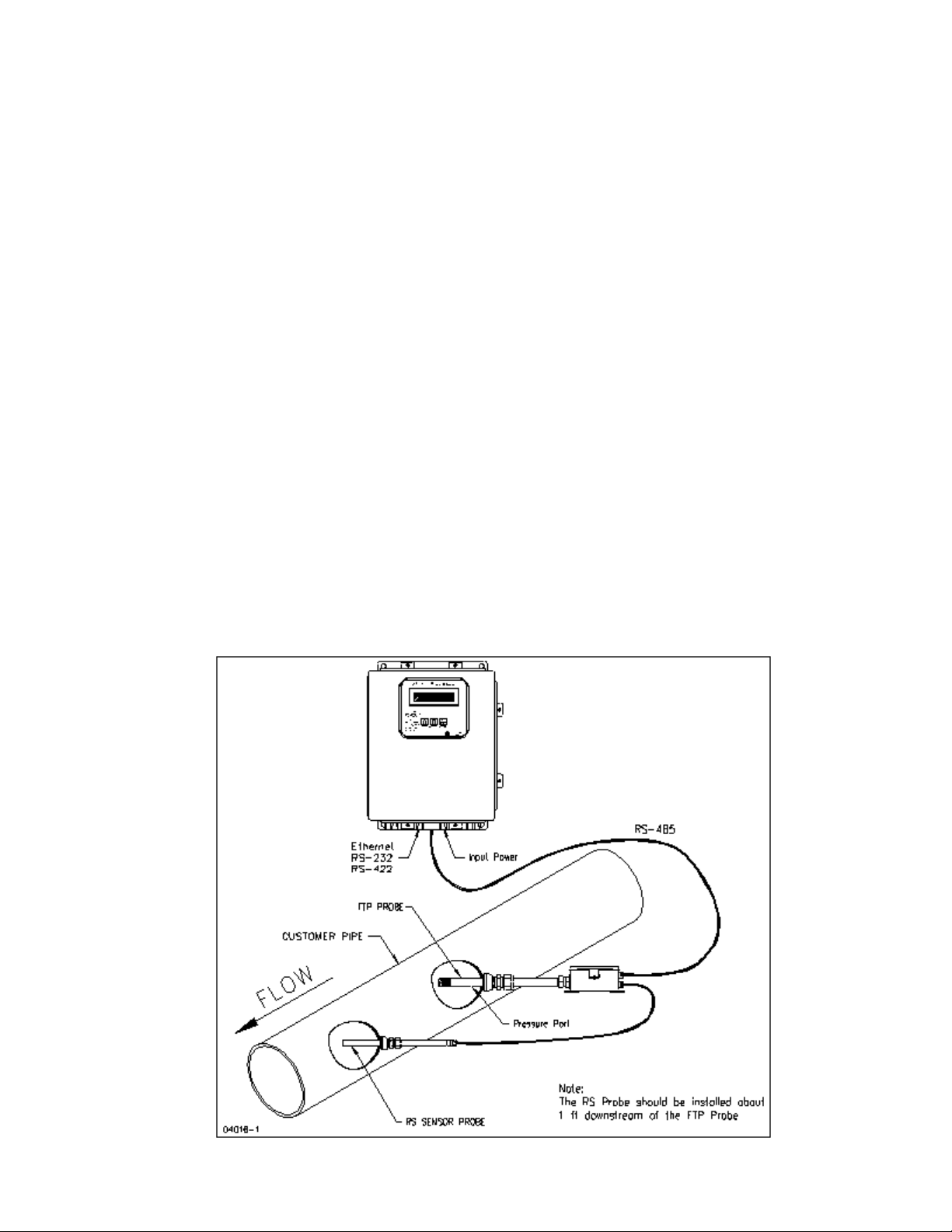
A RheoVac DR system consists of sensor probes reporting to a central signal conditioner and processor
unit. The sensing probes, consisting of multiple sensors configured in two separate probes (the standard
configuration is a main FTP probe and a RS probe), is installed in the vacuum line, generally between
the dryer and the exhauster. The RheoVac DR system is superior to all other methods in that it makes
no assumptions about the dynamics of the dryer and vacuum line environment. The main FTP probe
sensor head employs the patented Rheotherm® technology to provide an accurate mass flow
measurement. Additionally, temperature,pressure and water vapor relative saturation measurements are
made using a high accuracy platinum resistance temperature detector (RTD), a strain gauge pressure
sensor and a specially configured and calibrated water vapor saturation sensor.
System*
*USPNs 4,255,648; 5,485,754; 5,752,411; 6,385,974; 6,526,755
Figure 1 RheoVac DR
- 1 -
Page 4

1.2 PRINCIPLE OF OPERATION
The principal features of the RheoVac DR system are shown in Figure 1. At the heart of the RheoVac
DR system is the Rheotherm mass flow transducer, which uses the same patented thermal sensing
technique employed in all precision flow instruments manufactured by Intek. Two temperature sensors
are used one sensor is in thermal equilibrium with the flow medium and provides a temperature and
flow signal reference, while the second sensor is located near a constant power heater so that its
temperature is always above that of the fluid. The temperature of the heated sensor will vary with the
stream velocity of the fluid. Hence, the measured temperature differential between the reference sensor
and heated sensor is a function of flow rate, which is approximately proportional to the logarithm of
mass flow rate (USPN 4,255,968).
The Rheotherm flow sensor is calibrated to measure the total mass flow of the water vapor/air mixture.
From the other three measurements - temperature, pressure and relative saturation - the RheoVac DR
electronics converts the total mass flow signal from the probe into two components, air mass flow rate
and water vapor mass flow rate. This unique measurement method is disclosed in two separate patents
(USPN 5,485,754 & 5,752,411).
The RheoVac DR system is fully calibrated in the factory under dynamic fluid conditions similar to those
within the dryer vacuum line. Typically, field adjustments are not required.
1.3 TECHNICAL SPECIFICATIONS
1.3.1 Sensor (Probe) Specifications
Primary Cali bration Accuracy:
±5% of total mass flow
Repeatability:
±0.5% of reading
Operating Temperature:
Electronics: 40 to 120ºF (5 to 49ºC)
Probe: 40 to 160ºF (5 to 71ºC)
Never subject probe to temperatures above 210ºF (99ºC)
Operating Pressure:
0.5 to 30 inches Hg absolute
15 psi maximum
Storage Temperature:
-20 to 210ºF (-29 to 99ºC)
Storage Pressure:
15 psig (maximum)
Process Connection:
NPT
Hot tap assembly (optional, 1½” thread-o-let must be welded to pipe for
hot tap installation)
Wetted Surface:
300 Series SS and engineered plastic
- 2 -
Page 5

1.3.2 Main Electronics (Remote or PC) Signal & Data Access
Local Display:
Back-lit LCD
Selectable display of air mass flow and 6 additional instrument output parameters
Parameter scrolling
Metric/English units
Input Power:
100-250 Vac, 50/60 Hz
Signal Output or Data Access:
RS-232/RS-422/Serial Modbus, Ethernet, TCP/IP
Eight 4-20mA signals (optional)
Wireless (Optional)
OPC (Optional)
Temperature Environment:
Operating: 40 to 120
/F (5 to 49/C)
Storage: -20 to 210/F (-29 to 99/C)
1.4 PRECAUTIONS AND RECOMMENDATIONS
Read the entire manual before installing and operating the RheoVac DR system.
Carefully select the best location for installation of the probe(s). Access, clearances, freedom
from standing water, and straight-run should all be considered when selecting probe
locations.
Use reasonable care in handling the probes the sensing components are delica te. Do not
bend the probes, damage the tips, or obstruct the sensing ports. If shipping the unit, make
sure the probes are adequately protected from foreign objects and damage; save and reuse
factory provided custom probe protector and shipping boxes.
Use proper input power it must be between 100 and 250 Vac (nominal 120/240 Vac) at
50/60 Hz (60 Hz nominal).
Confirm the line and environmental temperature is always below the probe and electronics
ratings never operate a probe at or subject it to temperatures or pressures beyond its
specified limits. (See SECTION 1.3)
.. WARNING - Never allow live high temperature steam to flow either direction in
the line where a probe is located.
Keep moisture out of the enclosures once all service connec tions are made, make sure the
enclosure lids are tightly closed and all gaskets are in place. Seal all conduit lines.
The RJ45 is the recommended network connection for all data traffic (as opposed to serial
and 4-20 mA communication).
Intek recommends a service contract to ensure probes are within calibration specifications
and electronics are maintained with appropriate updates. Instrument probes should be
returned to the factory for inspection and calibration service every two years.
- 3 -
Page 6

SECTION 2 — INSTALLATION
2.1 INSTALLATION
These instructions are generalguidelines for the installation of RheoVac DR instruments in their standard
configuration. Additional information pertaining to your unit is covered in SECTION 6 CUSTOM
INFORMATION. Carefully read these instructions prior to installing the equipment. Also, see
preceding SECTION 1.4 PRECAUTIONS AND RECOMMENDATIONS.
2.2 RheoVac DR SYSTEM INSTALLATION/SITE SELECTION
The RheoVac DR can be configured with one or two probes, with the two probe being the standard
configuration. In the standard two-probe configuration, the main probe (FTP) is the larger probe, and
the relative saturation (RS) sensor is located in a second probe, separate from the remaining primary
sensors in the FTP probe. The RS probe is typically installed in the same line at a location slightly
downstream of the FTP probe.
2.2.1 Probe Site Selection
The location for the probe pair should be selected so as to provide the probe sensing area
with well-established smooth flow, uniform system temperature and pressure, and consistent
non-liquid phase flow medium. Pipe sections ahead of a probe, in which water can
accumulate, must be avoided. Refer to Figure 2 and select the most preferred location for
the probe pair. Do not install the probes beyond any “trap” sections as shown in Figure 2,
Configurations B and D. Special installation instructions unique to your unit, where
applicable, will be noted in SECTION 6.3 SPECIAL INSTRUCTIONS. Refer to this section
now to review special instructions.
Check installation clearance. The installation location should allow sufficient clearance for
ease of probe removal (for servicing), including the required clearance space for the hot tap,
where used. Be sure there are no obstructions around the vacuum line that will interfere with
probe insertion. Figure 3 shows the proper insertion angle. THIS ORIENTATION IS
IMPORTANT FOR PROPER OPERATION, particularly if liquid water is expected to wet
the wall surfaces of the probe(s).
Observe the selected sites; check for ease of access. They should be convenient for the
removal and replacing probes at any time for service; without requiring ladders, building
scaffolding or waiting for plant shutdown.
Check operating conditions. The temperature and pressure limits (see TECHNICAL
SPECIFICATIONS; SECTION 1.3) of the unit should be checked to ensure compatibility
with your application.
- 4 -
Page 7
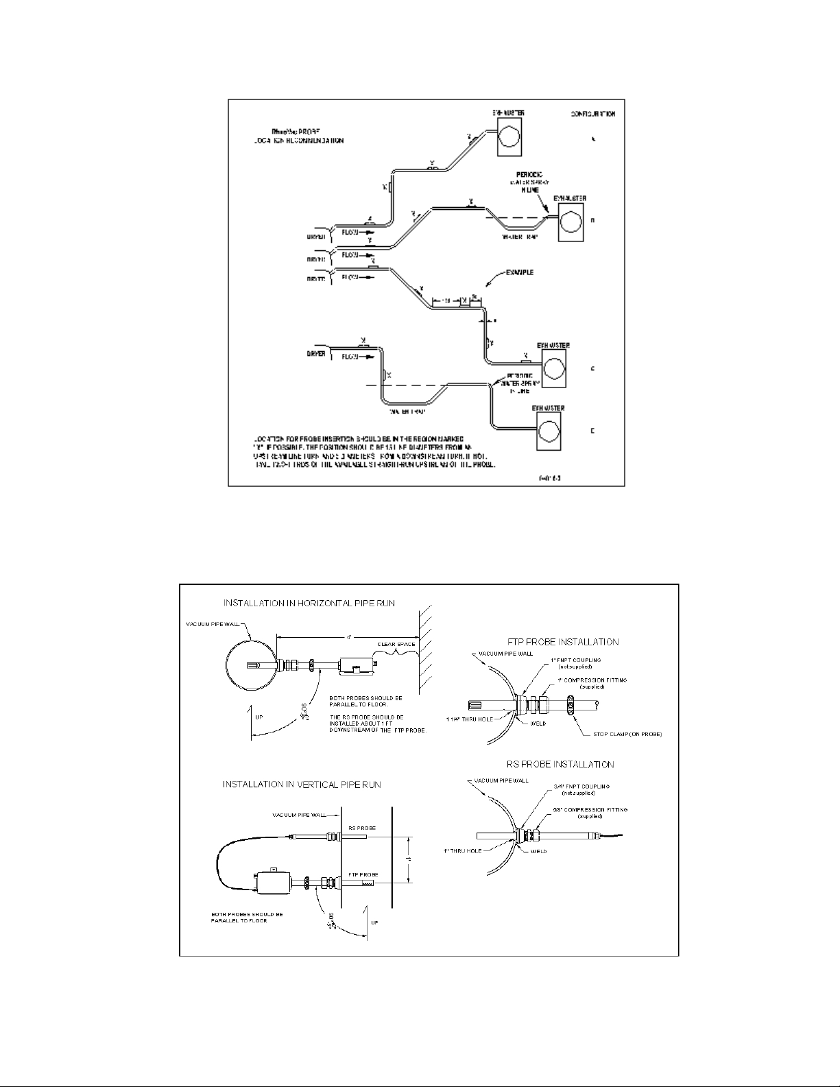
Figure 2 RheoVac DR Probe Insertion Recommendation
Figure 3 Probe Installation Detail
- 5 -
Page 8

2.2.2 Electronics Unit Site Selection
The RheoVac DR system may have up to three electronics enclosures; a main processor box, an
optional distribution box, and an optional transmitter box. These enclosures should be installed
in a convenient indoor location and should be kept away from direct sources of heat. The
maximum temperature rating of electronics is 120°F; ensure that this temperature will not be
exceeded inside the enclosure. Once the wiring connections are made, close and latch down the
box lid to protect the contents from damage and debris. The enclosures should be located in a
dry area and should be kept clamped shut during normal operation. Do not allow water to get
into the enclosures. If installed outdoors, build a roof over all enclosures to prevent potential
water infiltration, or direct sunlight to overheat contents.
A. Processor Enclosure: This 12x10 NEMA 4 enclosure houses the display and central
processing unit. Input power (100-250 Vac, 50/60 Hz) is connected inside this enclosure.
This enclosure should be installed in a convenient location and should be kept away from
direct sources of high heat, such as uninsulated steam lines.
B. Distribution Box (optional): This 8x6 NEMA 4 enclosure is typically located near the probe
that is closest to the processor enclosure unit. It is connected to the main processor with an
RS-485 bus DeviceNet™ cable, which can be hundreds of feet long. The probe and
transmitter RS-485 cable connections are also made within this box. The probe and
transmitter cable lengths should be 15 ft. or less.
C. Transmitter Box (optional): This 10x8 NEMA 4 enclosure contains terminals for accessing
the optional eight 4-20mA signals. It can be located in or near the control room so that the
4-20 wires do not have to be run from the plant floor. An RS-485 DeviceNet cable connects
the distribution box to the transmitter box. (There are restrictions on how this can be done,
so check manual SECTION 6, or contact the factory.)
2.3 PROBE INSTALLATION
!!WARNING!! The FTP probe and the RS probe(s) contain components and materials that
have a temperature rating limit of 210°F. If line and fluid temperatures are anticipated to exceed
this limit, the probe(s) must be removed from the vacuum pipe before and must not be reinstalled
until the problem condition has passed. Failure to do this can result in severe damage to the
sensor probe(s), especially when steam enters the vacuum pipe due to vacuum pump operating
anomalies. If Steam Jet Air Ejectors are used, always
pump start up and do not reinstall the RS probe until stable operating conditions are achieved.
A. NPT/Hottap Installation
1. Check hardware. Verify that the probe slides easily through the NPT fitting or hottap
assembly and pipe penetration hole.
2. Verify there are the necessary minimum probe insertion clearance four (4) feet- between
pipe surface and any obstruction.
3. For NPT fitting installation, ensure that the threaded mating fittings (not provided) for
mounting the sensing probe(s) are installed at the proper locations in the process line.
Typically, 1" threaded couplings are needed for the FTP and the RS probes.
remove the RS probe from the line before
- 6 -
Page 9
4. If using a hottap: install the mounting hardware; drill a 1½” through-hole, center the
thread-o-let over the hole and weld it onto the dryer vacuum pipe; thread the hottap
assembly into the thread-o-let. Use thread tape or pipe dope to seal the connection.
Alternate: weld thread-o-let to pipe wall, then drill a 1½" hole in pipe wall using a hottap
drill.
5. Make sure the probes are parallel to the floor (see Figure 3). Be sure location is
accessible for probe removal and maintenance.
B. Installing/Removing the Probe
1. Check proper installation direction and probe orientation. The FTP probe has a
directional arrow on the junction box. Before installing the unit, note proper flow
direction. This is important to instrument operation.
2. Check serial number (S/N). If more than one RheoVac DR system has been purchased,
make sure the first five digits of the serial numbers of the probe(s) match the first five
digits of the serial number of the main processor unit. The electronics and probe pairs
are a matched set. Mismatched components will not work correctly. The dash number
on the probe S/N is the probe number shown on the display. Record the probe pair
number and installation location for future reference.
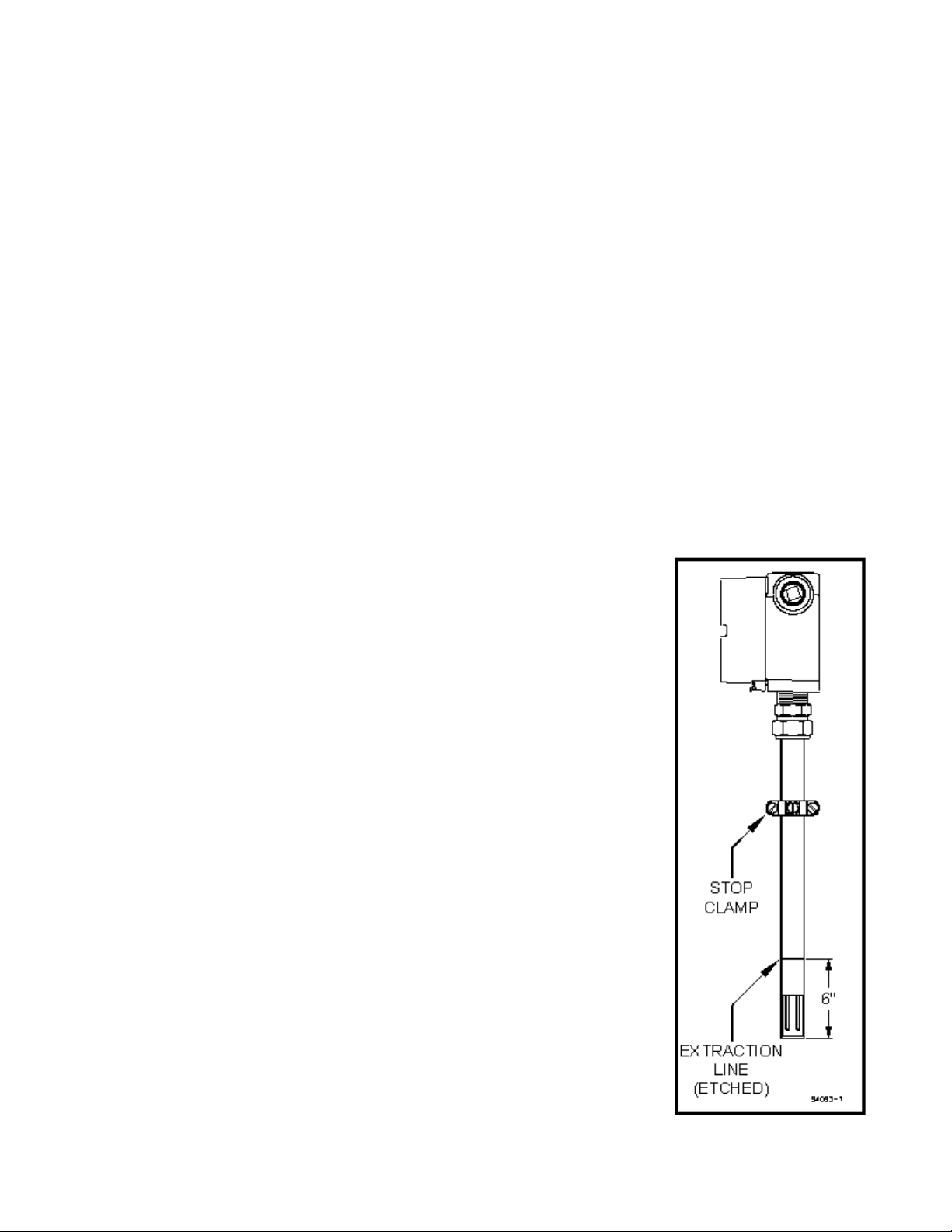
3. Verify stop clamp location (see Figure 4). A stop clamp is attached to each FTP probe
as an indication of its insertion depth. It is important that the stop clamp is securely in
place to position the sensors in the correct location and to ensure that the probes do not
contact the opposite pipe wall. Contact with the pipe wall
could damage the probe. The clamp’s location is determined
based on your submitted pipe diameter, as shown in
SECTION 6.2, and is marked with a groove on each probe
shaft. Refer to this mark if a stop clamp is inadvertently
moved. When installed in the line, the sensors in the probe
should be positioned in the middle of the pipe.
4. Prior to inserting probe, loosen the compression nut on the
thermocouple connector of the hot tap or the NPT fitting and
clean the inner surface of the thermocouple connector to
ensure it is free of particles that may cause probe damage.
5. Be sure to power up your RheoVac DR instrument system
and probe pair for at least 30 minutes before inserting probes
into the vent line. DO NOT leave probes in vent line
without power.
6. Install probes. The probes should be mounted through the
pipe wall using the hottap assembly or NPT fitting.
a. The FTP probe installs so that the two sensor tips are
side-by-side across the gas stream. Each probe has a
flow directional arrow on the junction box. Make sure
the probe orientation is correct.
b. The RS probe does not have an orientation requirement.
The RS probe has a 4 foot (1.2 m) cable with a plug-in
connector (with attached dust cap) for connecting to the
FTP probe. Unscrew the dust caps on the RS cable and
the FTP probe junction box, plug the cable connector in
securely first, before inserting the RS probe in the line.
- 7 -
Figure 4 Probe Stop
Clamp
Page 10
7. When installing under vacuum, do not allow the clamp to “slam” against the seal nut
upon opening the valve. Grasp each probe firmly, with hand against the seal nut,
before opening the ball valve. Allow the probe shaft to slide slowly through the
valve by controlling the amount of grip on the probe shaft. Do not let it slam against
the seal nut. Once fully inserted, tighten the seal nut. Special installation
instructions, if any, will be noted in SECTION 6.
8. It may be necessary to apply a force of about 23 lb (102 Newtons) to remove or
replace the probe under operating conditions. Firmly grip the probe shaft when
removing a probe from the line.
2.4 ELECTRICAL CONNECTIONS
IMPORTANT Inspect and VERIFY these electrical connections carefully. Improper
connection could damage electronic components and sensor function. If additional holes need
to be drilled in the processor enclosure, remove the electronics subassembly (mounted on a
mounting plate) and temporarily store inside an ESD bag in a safe, clean place. Do not drill with
electronics boards inside the enclosure.
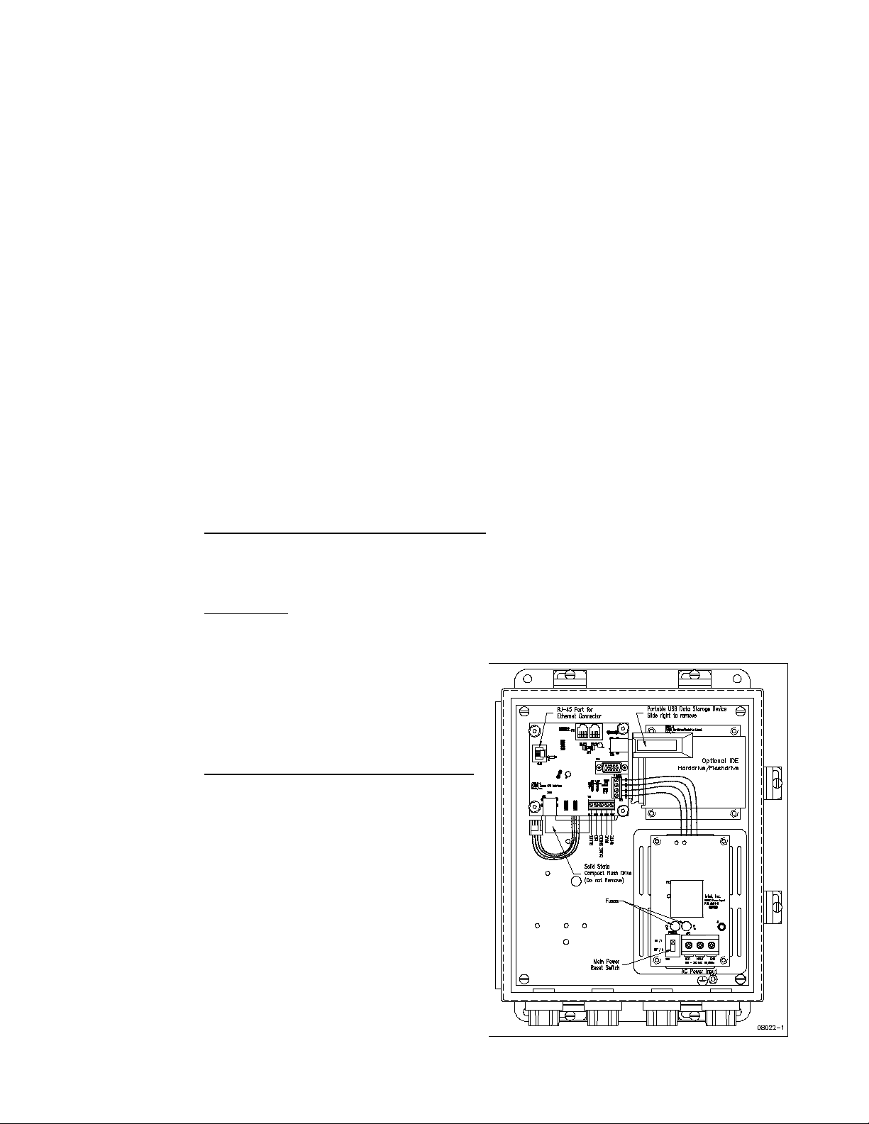
A. Main Processor Unit (see Figure 5)
1. Sensor Power and Communication Line
: Connect the distribution box to this main
processor box using the RS-485 communications/power cable. Follow indicated
connector color code. [communications: white (A), blue (B) and shield (SH); power:
24Vdc, red (+), and black (
2. Main Power
: Connect main power terminals to a dedicated 100-250Vac, single phase,
!)]
15-amp circuit. An external disconnect switch should be used for disconnecting power
to the system during outages. Power
connection wires should be at least 18
gauge and comply with accepted wiring
codes. SW1 on the power input PWA
(printed wiring board #01011-5) is used
for cycling power to reset.
3. Network Connection (Recommended)
:
The Ethernet connection at CN3 on the
CPU interface PWA (printed wiring
board #08017-1) is an RJ-45 style jack.
A 10-foot Ethernet Cat5 crossover cable
is supplied with the unit for laptop
connections. Intek recommends using
this connection for all data transmissions
and RheoVac communications because:
a. More measured data is accessible
through the network connection.
b. Software and calibration file updates
can be done remotely.
- 8 -
Figure 5 Electrical Connections and Set-up
Page 11
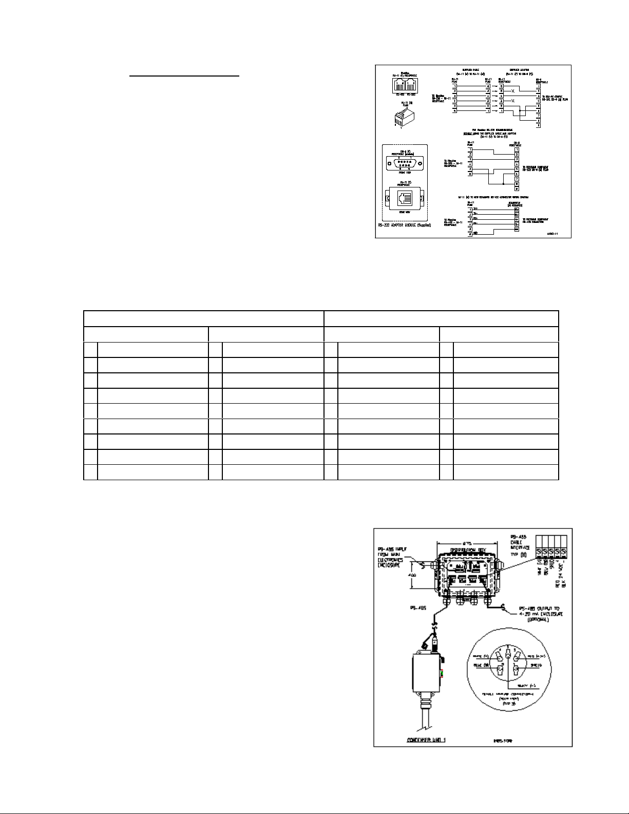
4. Serial Communication: Connector JP3 on the
CPU interface PWA (printed wiring board
#08017-1) is the RS-232 serial communication
interface. This interface should only be used for
distances of 20 feet or less, such as to a laptop
computer. A 20-foot serial cable with a DB-9
connector is available from Intekupon request (see
Figure 6 and Table I). An RS-422 serial
communication interface is present for long data
communications when configured without 4-20
mA outputs. Note: Intek recommends using the
network connection for all data transmissions and
RheoVac communications.
Figure 6 Serial Communication Interface
TABLE I. RJ-11 to DB Module Adapter
RS-232 CONFIGURATION RS-422 CONFIGURATION
RJ-11 Pin Out DB-9 Pin Out RJ-11 Pin Out DB-9 Pin Out
1 Tx (transmit) 1 N/C 1 Tx+ (transmit+) 1 Rx- (receive-)
2 N/C 2 Tx (transmit) 2 Tx- (transmit-) 2 Rx+ (receive+)
3 Rx (receive) 3 Rx (receive) 3 Rx+ (receive+) 3 Tx+ (transmit+)
4 N/C 4 N/C 4 Rx- (receive-) 4 N/C
5 Power (+5V) 5 Ground 5 Power (+5V) 5 Ground
6 Ground 6 Pulled high 6 Ground 6 Tx- (transmit-)
7 N/C 7 7 TBD
8 Pulled high 8 8 TBD
9 N/C 9 9
B. Distribution Box (optional) (see Figure 7)
1. Connect the RS-485 wires (blue, white and shield) and 24Vdc power (red and black)
from the main processor unit.
2. Install ½” liquid-tight conduit between the
distribution enclosure and the probes unless
½” rigid conduit is used for long distance
runs. Use a minimum of 6 feet of liquidtight at the probes.
3. The probe connector comes with an adapter
which allows the attachment of the ½”
flexible conduit connector.
4. Connect the probes to the distribution
enclosure using the manufacturer supplied
four conductor shielded cable to any of the
screw terminals labeled JP3 to JP6. Probe
cable connections are shown in Figure 7.
5. Optional - Connect the transmitter box to the
distribution box using the supplied RS-485
cable.
Figure 7 Distribution Box
- 9 -
Page 12

C. Transmitter Box (optional, See Figure 8) - For driving eight (8) remote 4-20 mA analog
signals from one RS-485 input port. Note: Intek recommends using the network connection
for all data transmissions and RheoVac communications.
1. Connect the RS-485 communications/power cable from the distribution box (RS-485:
white and blue wires; 24Vdc power: red and black wires).
2. Connect up to eight (8) signal wire pairs to the indicated terminals for isolated 4-20mA
outputs.
3. Figure 8 provides the RheoVac DR wiring detail for the 8 channel 4-20 mA outputs.
Table II provides the appropriate connection identification. Transmitters are configured
as active (transmitter sources the current) when shipped. To change to the passive mode
(receiver to source the current), extract each small 4-20 board, find the JP1 pins, and
move the two jumpers from the "Act" pins to the "Pass" pins (two positions to the right
of factory settings). Figure 9 shows the current output circuit. The figure also illustrates
the active mode and the passive mode configurations.
Figure 9 Optional Transmitter Box
TABLE II. Optional 4-20mA Configuration
Channel
1 Actual Volume Flow
2 Total Mass Flow
3 Water Vapor Flow
4 Pressure
5 Water Vapor to Air Mass Ratio
6 Relative Saturation
7 Air Mass Flow
8 Temperature
Output Parameter
Figure 8 4-20 mA Output Circuit
- 10 -
Page 13

D. FTP Probe: CAUTION— Do not cross thread connection. The FTP probe is supplied with
a convenient plug-in connector. The male side of the connector comes installed in the probe
junction box. The female side is usually shipped loose and must be installed onto the
supplied DeviceNet type 5711 cable once it is run from the Distribution Box to the probe.
The wiring detail for the female plug-in connector (Turck p/n B4151-0/9) can be seen in
Figure 10. These connectors will use either the “backshell nut” or “conduit connector”
depending on whether the cable is installed in a liquid-tight conduit. When installing without
conduit, use the backshell nut; when using liquid-tight conduit, use the conduit connector
with o-ring.
1. Slide all of the appropriate parts onto the cable as shown.
2. Strip the cable conductors as shown. The connector has 5 retention screws to hold the
wires in place. The use of crimp pins on the wires will greatly increase connection
reli abilit y.
3. Loosen all 5 retention screws (do not completely remove).
4. Insert the wires, in accordance with color-coding shown (see Figure 10, insert).
5. Tighten the retention screws on each wire.
6. Reassemble the connector parts.
Figure 10 Probe Connector Assembly
- 11 -
Page 14

SECTION 3 — OPERATION
3.1 GENERAL INFORMATION
The RheoVac DR system is compensated and linearized for a wide range of flowing medium
temperatures, pressures, and water vapor content. However, abrupt changes in these parameters can
cause the instrument to temporarily read improperly, which could lead to transient spikes in the flow
indication. In particular, if liquid (water) contacts the probe tips, there will be high flow indications until
all the water vaporizes. This is typically an infrequent occurrence and should not happen if the probe
is properly installed, according to instructions in SECTION 2 I NSTALLATION, and the vacuum
dryer is operating according to design.
3.2 SYSTEM START-UP
Verify wiring is according to instruction in SECTION 2.4. With all power off, place the power OFF/ON
switch, SW1, to “ON.” Close and latch down the main processor enclosure lid. While watching the
main processor display, apply power to the instrument. After about twenty seconds the display should
initialize to “Health Check in Progress” followed by additional initialization status messages. Within
two minutes the display should indicate “Air Mass Flow” rate in lb/hr units.
Upon a“cold” initial start-up of the RheoVacDR system, the probemay take severalminutes to giveaccurate
readings. During this time the probe is transitioning to thermal equilibrium conditions under vacuum.
3.3 PORTABLE USB DATA STORAGE/Warranty Registration Instructions
Intek’s warranty program is stated at the front of the manual. To validate warranty:
A. Locate portable USB Data Storage Device in the main electronics enclosure (Figure 5).
B. Grasp bracket and carefully remove portable USB Data Storage Device.
C. E-mail all RheoVac DR instrument data to techsupport@intekflow.
D. Replace portable USB Data Storage Device in the main electronics enclosure.
CAUTION - Do not attempt to use non-Intek approved USB flash drives with the RheoVac DR
instrument. Your RheoVac DR instrument may not have the proper drivers installed for other USB flash
drives. This may cause the RheoVac DR instrument to lock-up and require service.
3.4 DISPLAY
The RheoVac DR has a 2x20 alphanumeric scroll-through display that shows seven parameters for the
probe pair. The display shows Air Mass Flow, Water Vapor Mass Flow, Total Mass Flow, Temperature,
Pressure, Relative Saturation, or Actual Volume Flow (as well as Time/Date, Software Version, Serial
Number). To change the displayed parameter, press the Scroll Up or Down arrows. The display units
can be changed from English or Metric units by pressing the Units button.
If the RheoVac DR is configured for multiple probe pairs, the display will show all the probe serial
numbers one set at a time, one for each probe pair. The numbers will be in order, from the lowest serial
number to the highest, reading from left to right on the display. Example: 11621-1, 11621-2 and 11621-3.
- 12 -
Page 15

3.5 COMMUNICATIONS
A typicalRheoVac DR instrument has an Ethernet port and two serial communications choices (RS-232
or RS-422). The ethernet port can communicate via Windows® network Modbus or OPC. Eight 420mA output signals for the probe pair are optional. Each process variable is a linear, fully temperature
and pressure compensated value on any of these readable outputs. If supplied, all 4-20 mA output
signals are scaled such that 4 mA represents 0% of the rated full scale value (except temperature, which
is 0°C) and 20 mA represents 100% of the rated full scale value (temperature is 100°C). The standard
full scale values and definitions of all process variables are listed in Table III. Communication with the
RheoVac unit using Intek supplied software is discussed in Appendix A and Appendix B of this manual.
Note: Intek recommends using the network connection for all data transmissions and RheoVac
communications.
Table III. Process Variable Definitions and 4-20 mA (optional) Range
4-20 mA
PROCESS VARIABLE
FULL
SCALE
PROCESS VARIABLE DEFINITION
ACTUAL VOLUME FLOW
ACFM [m
TOTAL MASS FLOW
lbs/hr [kg/hr]
WATER VAPOR MASS FLOW
lbs/hr [kg/hr]
RheoVac PRESSURE
"Hg [mm Hg]
WATER VAPO R SPECIFIC
VOLUME
WATER to AIR MASS
RELATIVE SATURATION
PARTIAL PRESSURE,
“Hg (mm Hg)
AIR MASS FLOW
lbs/hr [kg/hr]
RheoVac TEMPERATURE
(ft³/lb)
RATIO
[%]
WATER
°F [°C]
3
/hr]
5000
[8,500]
10000
[4,536]
8000
[3,629]
30
[762]
N/A
20
100
N/A
1000
[453.6]
212
[100]
The actual volumetric flow rate of gases leaving the vacuum dryer. It is a
measure of exhauster capacity. Decreased capacity means pump
degradation.
The total mass flow r ate of the flowing gas. N ote: this value is not a
measure of air in-leak. It is a measure of total vapor and air removal and
exhauster op erating capacity.
The water vapor component of the flowing gas being removed from the
vacuum dryer.
Absolute pressure at the RheoVac DR probe head. Should be equal to or
less than turbine back pressure.
The inverse density of the water vapor present in the line. Not supplied as
4-20 mA output.
Ratio of water vapor flow rate to dry air flow rate. Defines “vacuum
quality.”
The perce nt concentration of water vapor in the extraction line relative to
saturation.
The partial pressure of water vapor in the vaccuum line. Not supplied as
4-20 mA output.
Actual measure of air mass flow rate passing the RheoVac DR sensor head,
normalized to standard conditions (70°F, 29.9" HgA).
4 mA = 0°C/32°F 20 mA = 10 0°C/212°F
Temperature of the flow media at the RheoVac DR probe head.
- 13 -
Page 16

3.6 DATA PROCESSING
A very important part of understanding your vacuum dryer system comes from evaluating the data that
is created and stored by the RheoVac DR instrument. The ability to evaluate data has been greatly
enhanced with the RheoVac DR by providing nearly unlimited data storage capacity. A data file is
created for each calender day that the monitor is operating. The ability to review stored data is
invaluable when troubleshooting vacuum dryer problems. The column headings for each archived data
file is seen in Table IV.
TABLE IV. Column Headings for Data Downloads and Archived Data
Time
Stamp
(Time of
day)
Actual
Volume
Flow
(ACFM)
Total
Mass Flow
(lbs/hr)
Water
Vapor
Mass Flow
(lbs/hr)
RheoVac
Pressure
(Hg abs)
Water
Vapor
Sp. Vol.
(ft³/lb)
Water to
Air Mass
Ratio
(lb/lb)
Relative
Saturation
(%)
H2O
Partial
Pressure
(Hg abs)
Air
Mass
Flow
(lb/hr)
Probe
Temp.
(°F)
RS
Temp.
(°F)
Raw Total
Mass Flow
(lbs/hr)
(°F)
)T
RS
Frequency
(Hz)
The importance of reviewing graphed data cannot be overstated. Reviewing data for normal operating
conditions will greatly decrease the time need to troubleshoot problem conditions when they arise. To
simplify the graphing process, an Excel add-in has been created by the technical support team at Intek
This Excel add-in graphing utility, called RheoGraph, is an automated graphing macro that imports and
graphs RheoVac DR data files. It is available on request.
The RheoGraph utility is contained in a self-extracting zip file called "RheoGraph.Rev...exe" on the user
interface software CD. Executing the file will begin the menu driven installation process. The default
installation path is to C:\RheoVac; do not change this path name during installation. The file
RheoGraph.xla will be copied to the installation folder along with help files, sample data, and a readme
text file. Microsoft Excel is required for the add-in to function.
Executing RheoGraph.xla will launch Excel and the graphing menu will appear. Selecting Auto will
prompt the user to enter Company, Plant, and Unit info, which will be placed in the graph titles. Then
the user is prompted to browse to the data file to be graphed. The data will be inserted into a spreadsheet
page and four graph pages will then be automatically added as separate tabs in the workbook. When the
graphs are complete, macro execution terminates.
Several advanced features are available by selecting Advanced on the Auto Start menu. For additional
help, use the keyboard arrow keys to set focus on any button, then press F1. An example is shown of
a graph made by RheoGraph showing air mass flow and water vapor mass flow.
- 14 -
Page 17

3.7 CUSTOM SOFTWARE
Custom software may be developed by the user to receive and archive RheoVac DR data into a computer
system. The electronics has a serial data protocol of 9600 baud, no parity check, eight data bits and one
stop bit (i.e., 9600,N,8,1). Each transmitted group of data is sent in a standard ASCII coded format
representing each process variable value, instrument identification and status information.
The data stream consists of 13 fields, followed by a carriage return <RETURN>. The first ten fields,
nine bytes each, are the process values. Following the process variables are the RheoVac serial number,
nine bytes, the process identification tag number, 15 bytes, and the RheoVac system status, seven bytes.
The data stream is then ended by a single <RETURN> byte (ASCII code 13). The total number of bytes
transmitted in each data stream is 122 bytes per probe including the trailing <RETURN>. This data
group is sent approximately once every three seconds. Table V shows the field names and number of
bytes in one data stream.
TABLE V. Serial Output Data Stream
Air
O
Actual
Volume
Flow
(ACF M)
9
bytes
Total
Mass
Flow
(lbs/hr)
9
bytes
Water
Vapor
Flow
(lbs/hr)
9
bytes
RheoVac
Pressure
("Hg abs)
9
bytes
Water
Vapor
Sp. V ol.
(Cu. ft/lb)
9
bytes
Water to
Air Mass
Ra tio
(lb/lb)
9
bytes
Relative
Saturation
(%)
9
bytes
H
2
Partial
Pressure
("Hg abs)
9
bytes
Mass
Flow
(lb/hr)
9
bytes
Probe
Temp.
(°F)
9
bytes
Instr.
Serial
Number
9
bytes
ID
Tag
No.
15
bytes
Status
7
bytes
Term.
<CR>
1
byte
Each of the first ten process values are sent in the fixed decimal format of XXXX.XXXX with leading
and trailing zeros inserted to maintain the nine character length. The next three fields are ASCII text
strings followed by the <RETURN>. Example: The nine bytes for an air mass flow of 10.0 lb/hr would
be: 0010.0000, or 48,48,49,48,46,48,48,48,48 ASCII.
- 15 -
Page 18

SECTION 4 — MAINTENANCE
4.1 GENERAL MAINTENANCE
Precautions should be taken to insure proper performance of all sensors. Since the quantification
technique involves signal measurements, care should be exercised to prevent build-up of dirt and/or
corrosive layers on the probe surface and on the various terminal strip connections. Periodic checks with
necessary cleaning should be performed to insure clean probes and terminals. The joints of the sensor
leads should occasionally be inspected for corrosion or presence of moisture.
4.2 CALIBRATION
The RheoVac DR instrument is calibrated at the factory in a calibration system which replicates the
vacuum dryer and vacuum line environment. The system is designed to calibrate the temperature,
pressure, water vapor relative saturation and flow sensor under the gaseous fluid conditions found within
the plant’s vacuum line.
In general, calibrations should be valid over a two year period if the probes are well maintained. Should
the unit require re-ranging or recalibration, note the serial number of the RheoVac DR instrument and
contact the factory concerning recalibration cost and turn around times. Refer to SECTION 5
CUSTOMER SERVICE of this manual for additional information. Contact Intek for calibration,
monitoring service plans, instrument service agreements as well as other Intek products and services.
4.3 SPARE PARTS
It is sometimes advantageous to have a spare probe pair. Should a spare probe pair be desired, it can be
ordered and stored for installation at any time. A spare probe will come with a parameter disk with
calibration files that will need to be uploaded to the main electronics along with instructions to complete
the update and install/replace the probe (see SECTION 4.4).
Spare fuses should be available for replacement of blown fuses. Appropriate fuses to stock are:
C Electronics: Slow blow 1A Wickmann fuse, part number 3721100041 or equivalent.
C Probe: Slow blow 500 mA Wickmann fuse, part number 3720500041 or equivalent.
There are no other normally recommended spare components to stock.
To replace the fuse in the main electronics: locate the AC Power Input board (#01011-5 shown in Figure
5) in the lower right hand corner of the main electronics box. Slide the power switch to the “OFF”
position to disable power to the electronics. The fuses are shown at locations F1 and F2 (spare). Gently
pull the fuse(s) from the socket and gently insert the replacement 1 Amp fuse(s) as appropriate. Slide
the power switch back to the “ON” position to enable power to the electronics. Close hinged lid and
verify display backlight is on. Clamp close the enclosure lid, and tighten the latch screws.
To replace the fuse in the probe: locate the AC Power Input board (#01011-5 shown in Figure 5) in the
lower right hand corner of the main electronics box, as above, to disable power to the probe. Gently pull
the fuse from the socket and gently insert the replacement 500 mA fuse. Close the probe electronics lid.
- 16 -
Page 19

Go to the main electronics enclosure and slide the power switch back to the “ON” position to enable
power to the electronics and the probe(s). Close hinged lid and verify display backlight is on. Clamp
close the enclosure lid, and tighten the latch screws.
4.4 TROUBLESHOOTING
Table VI provides a guide for plant personnel to identify causes of problems and determine appropriate
actions to resolve problems observed. If problems are encountered and factory assistance is desired,
please contact the factory.
TABLE VI. Troubleshooting Guide (diagnostic messages)
MESSAGE CODE
Description/Symptom
PROBABLE CAUSE ACTION
MSG-0
Communications not
being received from
probe(s)
MSG-1
Invalid data received
from probe(s)
MSG-2
Flow sensor heater
“OFF”
MSG-3
Relative saturation
sensor power “OFF”
MSG-4
RS heater “OFF”
MSG-5
Circuit issue
MSG-6
Temperatu re alarm
(above 210°F/99°C)
MSG-7
Wet probe
1. Improper cable hookup
2. Blow n main fuse
3. Failed RS-4 85 circuit
4. Damaged flow sensor
1. Failed RS-485 communications
component
1. Blown heater fuse
2. Failed electronic component
1. Probe temperature too high
2. Liquid water on probe tips
1. Component failure 1. Contact factory
1. Problem with circuitry 1. Contact factory
1. Steam in exhaust pipe
1. This usually indicates a vacuum dryer
design or operation problem that
requires corrective action.
1. Verify plug-in connector is mated
2. Check all cable connections
3. Check F1 fuse on probe board
4. Contact factory
1. Check wiring
2. Contact factory
1. Contact factory
1. Che ck to be sure p robe temperature is
<160°F
2. Contact factory
1. Remove probe or cool line ASAP!
Once line h as cooled down and probe is
reinstalled, check unit for proper
function.
1. Contact factory
MSG-8
RS sensor problem
Mass flow output
saturates high, will not
respond to flow changes
Mass flow output
saturates low, will not
respond to flow changes
1. RS sensor problem
1. Flow rate is not within range of
calibration
2. Blown heater fuse
3. Failed electronic component
1. Flow rate is not within range of
calibration
2. Failed electronic component
- 17 -
1. Rem ove from line , allow 24 hrs with
power on to dry out RS, sensor, reinsert
probe
2. Contact factory
1. Contact factory about re-ranging
instrument
2. Replace fuse
3. Co ntact factory
1. Contact factory about re-ranging
instrument
2. Contact factory
Page 20

When using the RheoVac DR software on a PC, the software may give you a “Communication Message.”
Use the information in TABLE VII and TABLE VIII to determine the source of this problem and
appropriate action.
TABLE VII. Troubleshooting Guide (serial connection software communication issues)
OBSERVATION PROBABLE CAUSE ACTION
Appears the first time
the application was
executed
Appea rs intermittently
after application has
been run ning normally
Completely stops
working after
application was been
running normally
Canno t be made to
work at all with Com3
or Com4
Note: Windows is a registered trademark of Microsoft Corporation in the United States and other countries.
1. Instrument not connected to the
software defaulted serial port
2. Communication connections not made
or instrument is not powered
1. Elec trical noise interfer ing with
communications
2. To o many applications running in
Windows
3. Ano ther application is conflicting with
this comm port or IRQ
1. Instrument has stopped
communicating
2. Loose or damaged communication
connection
1. Works fine on Com1 or Com2 but
does not wo rk on other port due to
other hardware co nflicts, such as a
modem
®
1. Change serial comm port setting and
hit “Retry”
2. Check connections and instrument
power
1. Change to RS-422 communications, reroute or shie ld cable
2. Close other applications until problem
self corrects
3. Change to a different comm port
1. Check instrument power or look at
instrument display for fault status
2. Check cable adapter at back of PC or
at any other splices or at instrument
1. Using Windo ws Control Panel System utility, check fo r IRQ or I/O
hardware conflict - ADVANCED
USERS ONLY
If the RheoVac DR instrument is operating without fault mode indications but output readings are
questionable, please send to Intek by telefax or e-mail at least 24 hours of data from the RheoVac DR
instrument/probe, along with other relevant plant process parameters and control data for the same time
period; an Intek engineer can review the data to provide support.
TABLE VIII. Troubleshooting Guide (ethernet connection software communication issues)
OBSERVATION PROBABLE CAUSE ACTION
1. Verify settings on the U IC outlined in
Appendix B
Connection error when
attempting to connect to
the instrument using the
supplied User Interface
Software (UIS)
Error occurs when
attempting to use the
UIS trending option or
file update option
1. Incompatible network settings on the
User Interface Computer (UIC)
2. IP address not identified
3. Ba d or incom patible Ca t5 cable
1. Lost connection
2. Incompatible UIS version
2. Reboot the UIC and RheoVac DR
while connected
3. Verify correct Cat5 cable (for p eer to
peer connection use crossover cable,
for networked connection use straight
cable)
4. Contact factory
1. Restart UIS
2. Contact factory
- 18 -
Page 21

4.5 HARDWARE AND SOFTWARE MODIFICATIONS AND UPGRADES
Note: The workgroup setting of the identification tab in Network Neighborhood Properties must be set
to WORKGROUP which is the instrument default setting. A Cat5 crossover network cable is required
for proper Ethernet network communication to the RheoVac DR instrument.
Normally, updating the main software residing on the RheoVac DR should be done at the factory.
However, software improvements or other factors may necessitate a user installation or upgrade of a new
main program. When this is required, instructions and software, as applicable, will be supplied.
If it is necessary to replace a probe, a new probe and diskette (with probe-specific calibration data), can
be ordered from Intek.
- 19 -
Page 22

SECTION 5 — CUSTOMER SERVICE
Intek's corporate philosophy is to help solve ourcustomers’ difficult flow measurement problems. When
you purchase a RheoVac DR system you also receive Intek's dedicated customer service. For sales or
product service, call your local representative or Intek directly at (614) 895-0301 8AM to 5PM EST/EDT
weekdays or fax us anytime at (614) 895-0319. E-mail inquiries should be sent to sales@intekflow.com
or techsupport@intekflow.com. Our customer service staff will provide assistance promptly.
5.1 QUESTION ON EXISTING HARDWARE
To allow us to help you more quickly, please have the serial number of the equipment available before
you call.
5.2 TROUBLESHOOTING
If you have reviewed SECTION 4.4 TROUBLESHOOTING and have questions, please call our
experienced engineers for assistance. In many cases we can solve a problem over the phone. Please
provide as complete a description as possible of the problems encountered.
5.3 FACTORY AND FIELD SERVICE
If you request field service to help with vacuum system performance problems, Intek has, for a fee,
experienced engineers available to meet your needs. For RheoVac DR instrument related questions, if
a problem cannot be solved over the phone, with your help, we will determine if factory service or field
service will be the best solution. When returning instruments/probes for factory service be sure to
carefully pack the instrument/electronics; extra care should be taken to protect the probes from damage
in shipment. Use the factory supplied PVC probe protection tube and custom shipping box for probes
when possible.
To request factory service on your instrument, a Return Material Authorization (RMA) and purchase
order is required. Our customer service staff will assist you with the required information to return
instruments for service.
5.4 NEW EQUIPMENT AND SERVICES
For information on Intek’s other instruments and services, such as a new RheoVac DR system, cooling
water flow and fouling meters, liquid or gas flow meter or flow switches, dryer system inspection,
analysis, or monitoring services, contact the Intek technical sales department by phone/fax/email. Our
staff will be pleased to answer all questions and provide our recommended solutions, instruments, or
services.
- 20 -
Page 23

SECTION 6 — CUSTOM INFORMATION
6.1 UNIT IDENTIFICATION
Model no.:
Serial no.:
Customer identification:
Calibrated for customer line size of inches, schedule
6.2 CONFIGURATION
The marked (X) items denote the configuration of this unit, as originally shipped from the factory.
Pipe Connection: : 1" MNPT connection for FTP (main, larger) probe
: 1" MNPT connection with adapter for RS probe
Q Hot tap with ________ MNPT connection
Input Power:
Outputs:
Analog: Q 8 outputs (4-20mA) for the probe (See Table III)
Digital:
: 100-250 Vac, 50/60 Hz
: Ethernet
Q RS232/RS422
Software: : RV User Interface Software and Rheograph utility on CD
Data Access: : Ethernet communication
Portable Data Storage: : Portable USB Data Storage Device
Enclosures Shipped: Cables Shipped:
: Processor Box : 5711 Interconnect cable (RS485) -
Q Distribution Box : Cat5 Ethernet cable - 10 ft
Q Transmitter Box Q RS232 communication - 20 ft
6.3 SPECIAL INSTRUCTIONS
The next page shows a sketch of a typical layout for aRheoVac DR system with all components located
near each other on the plant floor. Other configurations can be used, but there are rules as to how an
RS485 signal can be run, so if you are considering the use of significantly different arrangement for your
installation, please contact the factory (614-895-0301) to review your plans.
- 21 -
Page 24

APPENDIX A - RheoVac® Instrument User Interface Software
A.1 INTRODUCTION
User Interface Software (UIS) is provided on CD-ROM with every RheoVac instrument. This
software is used to communicate with the RheoVac unit from a User Interface Computer (UIC).
Some of the functions of the software can be performed using a serial cable, while all functions are
available using an Ethernet connection. An Ethernet crossover cable is provided with each RheoVac
instrument for the purpose of connecting a UIC directly to the RheoVac unit. The network functions
are also capable of being used from any network computer if the RheoVac instrument is connected
directly to the same network. In this case, the supplied crossover cable is not used; rather a straight,
high noise-immune Ethernet cable with RJ-45 plug is used (supplied by customer).
Most details regarding use of the software can be found in the active help files from the pull down
Help menu when using the software.
A.2 SOFTWARE INSTALLATION
A User Interface Computer (UIC) is required to access stored data and real time data of all
parameters. A laptop is suggested for easy access to the main processor unit. Intek does not supply
UICs but recommends the following System Requirements (minimum recommended):
Minimum System Requirements:
Windows 98, Windows NT, Windows 2000 or Windows XP Operating Systems
Pentium III, 400 MHZ processor with 128 MB RAM
SVGA 800 x 600 display
One CD-ROM drive
One 10/100 Ethernet Port
Recommended (Optional):
One 3.5 inch floppy disk drive (probe recalibration data files can be provided on diskette)
One RS-232 serial port with DB-9 connector
The User Interface Software should be installed onto the User Interface Computer. Install the
software by inserting the CD-ROM supplied with the manual into the CD-ROM drive and follow
the on screen prompts. A folder, C:\RHEOVAC will be created and files will be copied to this
folder. The executable file is RheoVac User Interface.exe and the others are drivers and
configuration files that must remain in the RHEOVAC folder. If a previous version of User
nd
Interface Software is on the UIC, you will need to launch the installer a 2
time.
A.3 USER INTERFACE SOFTWARE (UIS) SELECTION
After installation, the user interface is initiated by selecting [START\PROGRAMS\RHEOVAC\
RHEOVAC USER INTERFACE]. The main menu appears, prompting for a selection of RS-232
Serial Communication or Ethernet Communication Utility. A list of functions for each utility
appears below the green selection buttons.
I:\OFFICE\WPMANUAL\RV950 APPENDIX A3.wpd January 29, 2007
- A1 -
Page 25

Make sure the proper cable connection has been made and select the desired communication type
by clicking on either green button.
Figure A - Initial UIS computer Screen
A.4 RS-232/422 COMMUNICATION
This function requires a serial cable and connector, available on request, to connect the UIC and the
RheoVac instrument electronics. This connection allows the user to view real time data of important
parameters in a convenient gauge screen layout. From this gauge screen, the user may choose to
graph a single parameter for all probes, graph all parameters for a single probe, or archive data
directly to the UIC. The archive rate can also be adjusted. These are the only functions available
using serial communication. No commands or updates can be sent to the RheoVac instrument using
this communication method.
A.5 ETHERNET COMMUNICATION
User interface using Ethernet connection allows the user to: synchronize the RheoVac clock with
the UIC clock, retrieve stored data
1
, update files1, change line size, and access data. These network
access utilities are performed from a user interface computer (UIC) connected directly (peer-to-peer)
to the RheoVac unit using a crossover network cable or from a network computer when the RheoVac
instrument is connected to a network (LAN/WAN)2 using a straight Ethernet cable.
Each RheoVac instrument is identified by a unique network ID. The ID begins with the letter “R”
followed by the first five digits of the serial number found on the unit. (RheoVac Model 950 devices
which have not been serviced by the factory since 2005 may use the serial numbers or “RheoVac
1
File transfer can also be accomplished using Windows Explorer or Network Neighborhood
2
Specific network set-up at Intek may be required.
I:\OFFICE\WPMANUAL\RV950 APPENDIX A3.wpd January 29, 2007
- A2 -
Page 26

950" network ID). The user must select the network ID from the pull down menu following the
selection of Ethernet Communication utility from the Main Menu. If the Network ID is not in the
list, select Add New ID and enter the correct six character Network ID. When a new ID is added
to the list, it will be saved as the default for later use. Selecting the correct ID will initiate
communication with the RheoVac instrument. Software features, in addition to those detailed above,
are described within the User Interface Software itself.
A.6 SOFTWARE OPERATION
1. Set Clock
(available with Ethernet connection only): Initiating this action will reset the
RheoVac time clock to agree with the time on your UIC. Make sure the UIC has the
correct time before proceeding.
2. Change Line Size (available with Ethernet connection only): Use this option to update
the instrument’s stored line size variable for proper volume and mass flow calculations.
You should only need this option if the probe is installed in a pipe size that is different
from the value set in the instrument at the factory. In Ethernet Communication, click on
the Line Size tab. On the pull down menu for pipe size, click on the new value, then click
on Save. Click Load to verify that the change was saved by the instrument.
3. Update Files
recalibration, or some other change in the RheoVac operating software is needed, this tab
will be used. Do not use it until then. Instructions will be supplied at that time.
4. Retrieve Data
accessed via Ethernet connection from the
The
RheoVac software creates a new data file each day. The file name is in the
(available with Ethernet connection only): If the probes are ever returned for
(available with Ethernet connection only): Stored data can be easily
RheoVac instrument to the UIC.
following format:
MMDDYY - P.dat
where MM = two digit month
DD = two digit day
YY = two digit year
P = probe designator (1, 2, or 3)
.dat = file extension
These data files are stored in tab delimited text format. See SECTION 3.5 to process data.
To copy a file for analysis, you must access the files on the RheoVac instrument. Open
Windows Explorer on the UIC. Type \\Network ID\RHEOVAC\DATA (Network ID is
generally “R” plus the first 5 digits of the serial number; see section A.5) on the address
line and press enter. Be careful not to alter any support files in this data folder. Use
the copy/paste functions (copy - Ctrl C; paste - Ctrl V) to put data files (.dat) on the
UIC.
5. Monitor Data
(available with Ethernet or RS-232 connection): Once RS-232 or Ethernet
is selected, the first screen, Figure B, shows the most recent value for each parameter.
I:\OFFICE\WPMANUAL\RV950 APPENDIX A3.wpd January 29, 2007
- A3 -
Page 27

Click on the small graph image to view a historical graph of that parameter. S elec t
from all available probes by clicking on the Probe S/N menu.
Figure B - User Interface Software Data Monitor Feature
To do real-time graphing, select from the graph menu. The screen shown in Figure C
appears.
Figure C - User Interface Software Graph Feature
I:\OFFICE\WPMANUAL\RV950 APPENDIX A3.wpd January 29, 2007
- A4 -
Page 28

This screen can be divided into four parts:
1. The Chart (or charts)
2. The X-Axis Controls
3. The Legend
4. The User Menu
These four parts work together in the following ways: As soon as the software is opened and valid
communication is established, the data collected for each probe is plotted on the chart(s). The
newest data points are displayed on the right of the chart and push older data points to the left, much
like many old-style strip chart recorders.
The horizontal scroll bar immediately below the chart(s) can be used to select which data points (i.e.,
data from a specific timestamp) from the chart are displayed on the legend below. Data points can
be selected either by clicking-and-dragging the scroll bar pointer or by simply single-clicking a spot
on the scroll bar.
The four buttons below and to the left of the scroll bar labeled 30 min, 1 hour, 2 hour, and 4 hour
can be used to quickly set the x-axis range of the chart(s) and the scroll bar. When using these
buttons keep in mind that the maximum x-axis value is always used as a reference and only the
minimum displayed x-axis value will be changed. You can also change both the minimum and
maximum x-axis value by double-clicking them with your mouse and entering a new value with
your keyboard. Changing the range of the chart (X or Y axis) changes only the data that is displayed
and does not delete or alter the data in any way.
The blue block (time/date) to the right of the 4 hour button displays the timestamp for the data point
currently being pointed to by the horizontal scroll bar. If the scroll bar is in the right-most position,
this value will automatically update when new data is received from the connected instrument.
The legend at the bottom of the screen displays the value of the data being pointed to by the scroll
bar and also is used to control where each data parameter is plotted. To access this feature singleclick on any parameter in the legend. Two things will happen. First, the background color of the
selected parameter will change in the legend, and second, the parameter will disappear from the
chart if you are in single-chart mode or jump from one chart to the other if you are in dual-chart
mode.
Single-chart and dual-chart modes are the first two selections available in the chart user menu. Also
available in the chart menu are selections to choose between manual and auto scaling for the y-axis
and to reset the maximum x-axis value to the most recently collected data point.
The legend menu is used to select which parameter or which probe is displayed. If a parameter is
chosen from this menu, that parameter will be displayed for all probes connected to the instrument.
If a probe is selected, then all parameters for that probe will be displayed.
The archive menu is used to set the rate that data will be archived to the hard disk of the computer
on which the user has installed the User Interface Software. These selections have no effect on the
data that is stored every minute on the hard disk of the RheoVac instrument itself. Data archived
I:\OFFICE\WPMANUAL\RV950 APPENDIX A3.wpd January 29, 2007
- A5 -
Page 29

to the user’s hard disk is stored in the “C:\RHEOVAC\DATA\” directory. The data is subdivided
into folders for each probe. A new file for each probe will be created each day that data is archived.
A.7 WARRANTY REGISTRATION/TECHNICAL SUPPORT
Sending Data to Intek: IMPORTANT
If the instrument is equipped with a portable USB data storage device as shown in Figure 5 (in the
main manual), remove this storage device after one week of operation and send to "Intek, Inc., 751
Intek Way, Westerville, OH 43082" to activate/secure warranty registration. This storage device
is programmed to capture the initial baseline data recorded by the RheoVac instrument.
The following paragraph is applicable to RheoVac 950 instrument users only:
The availability of plant data for periods corresponding to the RheoVac data are important to proper
diagnostic evaluation. Plant data of interest to the factory for the same time period are: turbine back
pressure, hotwell temperature, load, and inlet and outlet circulation water temperatures. The plant
data is necessary for correlating RheoVac measured data. The availability of this information at the
factory is very important to Intek’s ability to assist you in troubleshooting your instrument and/or
to respond to inquiries. This provides a baseline for the system and will help us support you should
future system problems arise. Our experienced support engineers can access the “before” and “after”
effects of an upset and work with you to identify and understand the problem, and develop solutions.
Additionally, most air removal piping conditions that are detrimental to probe operation can be
diagnosed before probe damage occurs. For this reason, we require a data download one week after
RheoVac system is placed into service. The download activates the one year warranty service.
the
Alternately, you may send to the factory an initial week or so of data (zipped format is preferred). The
simplest way is to copy all data files and the ‘event.log’ file to your UIC and send it via email to
techsupport@intekflow.com.
Note: Windows is a registered trademark of Microsoft Corporation in the United States and other countries.
I:\OFFICE\WPMANUAL\RV950 APPENDIX A3.wpd January 29, 2007
- A6 -
Page 30

APPENDIX B - RheoVac DR Networking
B.1 INTRODUCTION
Use these instructions when making a peer-to-peer Ethernet connection between the RheoVac DR
and the User Interface Computer (UIC), or an Ethernet connection between the RheoVac DR and a
LAN. Locate the section that covers your operating software.
B.2 WINDOWS 98, or Windows ME
® ®
1. Ethernet Cable:
a. UIC Connection: use CAT5 network crossover cable (supplied by Intek) to connect the
Ethernet port of the UIC to the Ethernet port on the RheoVac DR.
b. LAN Connection: use CAT5 straight high noise-immune Ethernet cable (not supplied)
with RJ45 plug to connect the Ethernet port of the LAN to the Ethernet port of the
RheoVac DR.
2. Workgroup Identification: Unless otherwise requested, the Workgroup identification for the
RheoVac DR will be WORKGROUP, which is the instrument default setting. To check/set
the workgroup name: Right click on the Network Neighborhood icon on the UIC desktop.
Select Properties from the menu that appears. Select the ‘Identification’ tab of the Network
dialog box that appears. Verify that Workgroup is WORKGROUP.
3. Check for Installed Network Components: Right click on the ‘Network Neighborhood’ icon
on the UIC or LAN computer desktop. Select ‘Properties’ from the menu that appears.
Select the ‘Configuration’ tab of the Network dialog box that appears. In the list under “The
following network components are installed” there should be all three of the following:
Client for Microsoft Networks, Ethernet adapter, and NetBEUI (with the Ethernet adapter
identified on the same line next to it). Each will have a different icon associated with it; the
‘Client’ icon looks like a computer screen, the ‘Adapter’ icon looks like an adapter card, and
the ‘NetBEUI’ protocol icon looks like a cable in a T shape. If these components are not
installed, one or more of the following installations may be necessary. Note, the Windows
installation disk may be needed.
a. Installing Client for Microsoft Networks: If Client for Microsoft Networks is not in the
list of “The following network components are installed” then, do the following:
i. Click the ‘Add’ button next to the list.
ii. The Select Network Component Type dialog box will appear.
iii. Select ‘Client’ from the list then click the ‘Add’ button.
iv. Select ‘Microsoft’ from the Manufacturers list.
v. Select ‘Client for Microsoft Networks’ in the Network Clients list
b. Installing NetBEUI: If the NetBEUI (with the Ethernet adapter identified on the same
line next to it) is not in the list of “The following network components are installed”,
then do the following:
i. Search the installed network components list for the installed Ethernet adapter.
ii. Select the ‘Ethernet adapter’ and click the ‘Add’ button below the list.
I:\OFFICE\WPMANUAL\RV DR Appendix B.wpd August 1, 2004
-B1-
Page 31

iii. Select ‘Protocol’ from the Select Network Component Type dialog box.
iv. Click the ‘Add’ button next to the list.
v. The Select Network Protocol dialog box will appear.
vi. Select ‘Microsoft’ from the Manufacturers list.
vii. Select ‘NetBEUI’ from the Network Protocols list.
4. Networking with the RheoVac DR: If all of the items above are completed successfully, the
UIC or LAN computer should be able to network with the RheoVac DR. To search for the
RheoVac DR from the UIC or LAN computer:
Method 1
• Open Network Neighborhood.
• Each RheoVac instrument is identified by a unique network ID. The ID is an “R” plus
the first five digits of the serial number found on the unit.
• Look for the Network ID of your RheoVac DR. If the expected Network ID (See
previous paragraph) does not show up in the list, then type in the appropriate Address
line (\\“R” plus the first five digits of the serial number) and click the ‘Go’ button. This
may take several seconds and then a RHEOVAC folder will appear, which is the hard
drive of the RheoVac DR.
• Open the RHEOVAC folder then open the DATA folder. The \\Network ID
\RHEOVAC\DATA folder contains all the stored data. Use Windows copy/paste
(COPY - Ctrl C; PASTE- Ctrl V) to save the data files to the UIC or LAN computer.
Method 2
• Open My Computer
• Type in the Address line: \\Network ID (Network ID is defined above) and click the ‘Go’
button. This may take several seconds and then a RHEOVAC folder will appear, which
is the hard drive of the RheoVac DR.
• Open the RHEOVAC folder then open the DATA folder. The \\Network ID
\RHEOVAC\DATA folder contains all the stored data. Use copy/paste functions to save
the data files to the UIC or LAN computer.
B.3 WINDOWS NT, 2000
1. Ethernet Cable:
a. UIC Connection: use CAT5 network crossover cable (supplied by Intek) to connect the
Ethernet port of the UIC to the Ethernet port on the RheoVac DR.
b. LAN Connection: use CAT5 straight high noise-immune Ethernet cable (not supplied)
with RJ45 plug to connect the Ethernet port of the LAN to the Ethernet port of the
RheoVac DR.
2. Workgroup Identification: Unless otherwise requested, the Workgroup identification for the
RheoVac DR will be WORKGROUP. To check/set the workgroup name: Right click on the
‘My Computer’ icon on the UIC or LAN computer desktop. Select ‘Properties’ from the
menu that appears. Select the ‘Network Identification’ tab of the System Properties dialog
box that appears. Verify that Workgroup is WORKGROUP.
3. Check for Installed Network Components: Click the ‘Start’ button, select ‘Settings’, select
‘Network and Dial-up Connections’. Or, right click ‘My Network Places’ and select
I:\OFFICE\WPMANUAL\RV DR Appendix B.wpd August 1, 2004
-B2-
Page 32

‘Properties’. Highlight the Local Area Connection that represents the Ethernet adapter.
Right click on ‘Local Area Connection’ and select ‘Properties’. Under "Components
checked are used by this connection:" look for ‘Client for Microsoft Networks’ and
‘NetBEUI Protocol’. If these components are not installed, one or more of the following
installations may be necessary. Note, the Windows installation disk may be needed as well
as administrator security rights.
a. Installing Client for Microsoft Networks: If Client for Microsoft Networks is not in the
list of "The following network components are installed" then, do the following:
i. Click the ‘Install’ button below the list.
ii. The Select Network Component Type dialog box will appear.
iii. Select ‘Client’ from the list then click the ‘Add’ button.
iv. Select Microsoft from the Manufacturers list.
v. Select ‘Client’ for Microsoft Networks in the Network Client list.
vi. Click ‘OK’.
b. Installing NetBEUI: If the NetBEUI (with the Ethernet adapter identified on the same
line next to it) is not in the list of "The following network components are installed," then
do the following:
i. Click the ‘Install’ button below the list.
ii. The Select Network Component Type dialog box will appear.
iii. Select ‘Protocol’ and click the ‘Add’ button.
iv. The Select Network Protocol dialog box will appear.
v. Select ‘NetBEUI’ from the Network Protocol list.
vi. Click ‘OK’.
4. Networking with the RheoVac DR: If all of the items above are completed successfully, the
UIC or LAN computer should be able to network with the RheoVac DR. To search for the
RheoVac DR from the UIC or LAN computer:
• Open My Computer
• Each RheoVac instrument is identified by a unique network ID. The ID is an “R” plus
the first five digits of the serial number found on the unit.
• Look for the Network ID of your RheoVac DR. If the expected Network ID (See
previous paragraph) does not show up in the list, then type in the appropriate Address
line (\\“R” plus the first five digits of the serial number) and click the ‘Go’ button. This
may take several seconds and then a RHEOVAC folder will appear, which is the hard
drive of the Rheovac DR.
• Open the RHEOVAC folder then open the DATA folder. The \\Network ID
\RHEOVAC\DATA folder contains all the stored data. Use Windows copy/paste (COPY
- Ctrl C; PASTE- Ctrl V) to save the data files to the UIC or LAN computer.
B.4 Windows XP
®
1. Ethernet Cable:
• UIC Connection: use CAT5 network crossover cable (supplied by Intek) to connect the
Ethernet port of the UIC to the Ethernet port on the RheoVac DR.
• LAN Connection: use CAT5 straight high noise-immune Ethernet cable (not supplied)
I:\OFFICE\WPMANUAL\RV DR Appendix B.wpd August 1, 2004
-B3-
Page 33

with RJ45 plug to connect the Ethernet port of the LAN to the Ethernet port of the
RheoVac DR.
2. Workgroup Identification: Unless otherwise requested, the Workgroup identification for the
RheoVac DR will be WORKGROUP. To check/set the workgroup name: Click the ‘Start’
button and select ‘Control Panel’. Right click on the ‘System’ icon and select ‘Open’. Select
the ‘Computer Name’ tab. Verify that Workgroup is WORKGROUP. Use the change
button to type in a new Workgroup if needed.
3. Check for Installed Network Components: Click the ‘Start’ button and select ‘Control Panel’.
Right click on the ‘Network Connections’icon and select ‘Open’.Or, click the ‘Start’ button,
select ‘Connect To’, then select ‘Show all connections’. Highlight the Local Area
Connection that represents the Ethernet adapter. Right click the icon and select ‘Properties’.
In the new window that pops up, under “This connectionuses the following items:”, look for
Client for Microsoft Networks, NWLink NetBIOS, and NWLink IPX/SPX/NetBios
protocols. If these components are not installed, one or more of the following installations
may be necessary. Note, the Windows installation disk may be needed as well as
administrator security rights.
a. Installing Client for Microsoft Networks: If Client for Microsoft Networks is not in the
list of “This connection uses the following components:” then, do the following:
• Click the ‘Install’ button below the list.
• The Select Network Component Type dialog box will appear.
• Select ‘Client’ from the list then click the ‘Add’ button.
• Select ‘Microsoft’ from the Manufacturers list.
• Select ‘Client for Microsoft Networks’ in the Network Client list.
• Click ‘OK’.
b. Installing NWLink NetBIOS: If NWLink NetBIOS is not in the list of “This connection
uses the following components:” then do the following:
• Click the ‘Install’ button below the list.
• The Select Network Component Type dialog box will appear.
• Select ‘Protocol’ and click the ‘Add’ button.
• The Select Network Protocol dialog box will appear.
• Select ‘NWLink NetBIOS’ from the Network Protocol list.
• Click ‘OK’.
c. Installing NWLink IPX/SPX/NetBIOS: If NWLink IPX/SPX/NetBIOS is not in the list
of “This connection uses the following components:” then do the following:
• Click the ‘Install’ button below the list.
• The Select Network Component Type dialog box will appear.
• Select ‘Protocol’ and click the ‘Add’ button.
• The Select Network Protocol dialog box will appear.
• Select ‘NWLink IPX/SPX/NetBIOS’ from the Network Protocol list.
• Click ‘OK’.
I:\OFFICE\WPMANUAL\RV DR Appendix B.wpd August 1, 2004
-B4-
Page 34

4. Networking with the RheoVac DR: If all of the items above are completed successfully, the
UIC or LAN computer should be able to network with the RheoVac DR. To search for the
RheoVac 950 from the UIC or LAN computer:
• Open My Computer
• Each RheoVac instrument is identified by a unique network ID. The ID is an “R” plus
the first five digits of the serial number found on the unit.
• Look for the Network ID of your RheoVac DR. If the expected Network ID (See
previous paragraph) does not show up in the list, then type in the appropriate Address
line (\\“R” plus the first five digits of the serial number) and click the ‘Go’ button. This
may take several seconds and then a RHEOVAC folder will appear, which is the hard
drive of the RheoVac DR.
• Open the RHEOVAC folder then open the DATA folder. The \\Network ID
\RHEOVAC\DATA folder contains all the stored data. Use Windows copy/paste (COPY
- Ctrl C; PASTE- Ctrl V) to save the data files to the UIC or LAN computer.
I:\OFFICE\WPMANUAL\RV DR Appendix B.wpd August 1, 2004
-B5-
 Loading...