

Page 1

CONDENSER
MONITORING SYSTEM
with
RheoVac® and Rheotherm® Instruments
Installation & Operation Manual
Page 2

Intentionally left blank
Page 3

TABLE OF CONTENTS
SECTION 1 - GENERAL INFORMATION ...............................................................................................1
1.1 INTEK’S POWER INDUSTRY SERVICES ................................................................................................................ 1
1.2 PURPOSE AND FUNCTION ....................................................................................................................................... 2
1.3 TECHNICAL SPECIFICATIONS – check custom page to determine which components apply to your CMS .......... 3
1.3.1 Main Electronics (SCADA, RTU and HMI) ......................................................................................................... 3
1.3.2 RheoVac Multi-Sensor Probe (MSP) .................................................................................................................... 3
1.3.3 Rheotherm Cooling Water Flow and Fouling (CWFF) Meters ............................................................................. 4
1.3.4 Pressure/Temperature (PT) Probe ......................................................................................................................... 4
1.3.5 Thermocouple (TC) Temperature Sensors and Arrays ......................................................................................... 4
1.3.6 High Spatial Density Temperature Sensors and Arrays ........................................................................................ 5
1.4 WARNINGS , PRECAUTIONS AND RECOMMENDATIONS ........................................................... 6
SECTION 2 - INSTALLATION .................................................................................................................7
2.1 HARDWARE INSTALLATION .................................................................................................................................. 7
2.1.1 RheoVac Multi-Sensor Probes .............................................................................................................................. 7
2.1.2 PT Probes ............................................................................................................................................................ 10
2.1.3 Rheotherm CWFF Meters and Temperature Sensors .......................................................................................... 10
2.2 ELECTRICAL CONNECTIONS................................................................................................................................ 11
2.2.1 Main Electronics – contains the SCADA and HMI components ........................................................................ 12
2.2.2 Satellite Electronics (only provided with systems that have several instruments) .............................................. 13
2.2.3 Distribution Box (see Figure 6) – For distributing RS485 communication and 24VDC .................................... 13
2.2.4 4-20mA Transmitter Box (optional) – For driving eight (8) remote 4-20 mA analog signals ............................ 14
2.2.5 RheoVac MSP and PT Probe Connector Assembly ............................................................................................ 16
2.2.6 Rheotherm CWFF Meters and Temperature Sensors Connections ..................................................................... 17
SECTION 3 - USER INTERFACE AND DATA RETRIEVAL ..............................................................18
3.1 MENUS ....................................................................................................................................................................... 18
3.1.1 Compressing Data (to USB Stick) ...................................................................................................................... 18
3.1.2 Change Line Size (i.e., pipe diameter) ................................................................................................................ 20
3.1.3 Reboot ................................................................................................................................................................. 21
3.1.4 Cancel ................................................................................................................................................................. 21
3.2 UPLOADING TO INTEK’S SECURE FTP SITE FOR DATA EVALUATION ...................................................... 22
SECTION 4 - COMMUNICATION METHODS .....................................................................................24
4.1 ANALOG OUTPUT ................................................................................................................................................... 24
4.2 MODBUS .................................................................................................................................................................... 24
4.2.1 Modbus TCP ....................................................................................................................................................... 26
4.2.2 Serial Modbus ..................................................................................................................................................... 26
4.2.3 Modifying the Modbus Configuration File ................................................................................................ ......... 28
4.2.4 Modbus Troubleshooting .................................................................................................................................... 29
4.3 OPC – (OLE for Process Control) ............................................................................................................................... 30
4.3.1 Connecting .......................................................................................................................................................... 30
4.3.2 Adding Process Variables ................................................................................................................................... 30
SECTION 5 - TROUBLESHOOTING .....................................................................................................31
5.1 COMMON ISSUES .................................................................................................................................................... 33
SECTION 6 - MAINTENANCE GUIDE..................................................................................................34
6.1 WATERBOX INSTRUMENTS .................................................................................................................................. 34
6.2 CALIBRATION .......................................................................................................................................................... 34
6.3 SOFTWARE UPDATES ................................................................ ................................................................ ............. 34
6.4 ADDING/REPLACING SENSORS/INSTRUMENTS .............................................................................................. 34
SECTION 7 - CUSTOMER SERVICE .....................................................................................................35
7.1 TROUBLESHOOTING .............................................................................................................................................. 35
7.2 FACTORY AND FIELD SERVICE ................................................................ ................................ ........................... 35
7.3 CONSULTING SERVICES ........................................................................................................................................ 35
7.4 CONDENSER MANAGEMENT AND RheoVac/CMS TRAINING ......................................................................... 36
SECTION 8 - CUSTOM INFORMATION ...............................................................................................37
8.1 UNIT IDENTIFICATION AND CONFIGURATION ............................................................................................... 37
8.2 SPECIAL INFORMATION ........................................................................................................................................ 37
September 2013 i © Intek, Inc. 2013
Revision D
Page 4

WARRANTY
Intek, Inc. warrants each Rheotherm, RheoVac and CMS product to be free
from defects in material and workmanship under normal use and service;
Intek's obligation under this warranty being limited to making good any
part or parts thereof which shall, within one (1) year after delivery of such
product to the original purchaser, be returned to Intek with transportation
charges prepaid and which Intek's examination shall disclose to its
satisfaction to have been thus defective; this warranty being expressly in
lieu of all other warranties, express or implied and all other obligation or
liabilities on Intek's part. The purchaser will assume all responsibility and
expense for removal, decontamination and reinstallation of equipment.
Rheotherm flow meters are manufactured under United States patent numbers 4,255,968, 4,942,763, 4,949,578 and 5,445,018.
Rheotherm circulating water flow and fouling meters are patent pending in the USA. RheoVac instruments are manufactured
under United States patent numbers 4,255,968, 5,485,754, 5,752,411 and 6,526,755. CMS products incorporate Rheotherm and
RheoVac technology as well as technology under US patent numbers 6,526,755, 7,065,970, 7,926,277 and international patents.
Intek, Rheotherm, and RheoVac are registered trademarks of Intek, Inc.
September 2013 ii © Intek, Inc. 2013
Revision D
Page 5

SECTION 1 - GENERAL INFORMATION
1.1 INTEK’S POWER INDUSTRY SERVICES
Intek manufactures RheoVac condenser and air in-leak monitors, Rheotherm circulating water
flow and fouling meters, flow meters, flow switches, as well as specialty temperature and pressure
measurement instruments. These specialty instruments for the power industry provide continuous
monitoring of critical steam surface condenser parameters important to plant thermal performance and
life cycle.
The data from these instruments have been used to gain a unique comprehensive understanding
of steam surface condensers and the condensation process. This understanding has enabled Intek to help
customers troubleshoot condensers with greater speed and accuracy than ever before. Intek has
expanded service offerings and developed an online information website for steam surface condensers,
available at www.MyCondenser.com.
Intek has also taken advantage of its aerospace design tools and design expertise for the purpose
of retrofitting condensers to maximize performance and improve condensate chemistry. Intek has
transformed underperforming condensers into some of the best performing condensers in the world.
The condenser services team under Dr. Joseph Harpster’s leadership has also sought to educate
the industry by contributing volumes of material to ASME and EPRI regarding proper condenser
measurement and steam flow dynamics. Intek conducts a unique Condenser Operations and
Management Workshop for continuing education purposes. Tutorials and case studies are also available
at www.MyCondenser.com for registered users.
Intek is The Gateway to
Improved Condenser Performance, Fast Response Maintenance and Optimized Operations
September 2013 1 © Intek, Inc. 2013
Revision D
Page 6

1.2 PURPOSE AND FUNCTION
The Condenser Monitoring System (CMS) integrates unique instruments allowing
comprehensive examination of condenser performance. These unique instruments are specifically
designed to provide direct measurement of performance degradation mechanisms and data that exceed
the requirements of instrumentation outlined in ASME PTC 12.2. A complete system will provide data
used to derive information for quantifying specific degradation mechanisms such as microfouling,
macrofouling, cooling water flow, waterbox fill, air binding, low vacuum equipment capacity and
condensate inundation. This information can also be used to evaluate the cooling water system changes,
fouling control systems, waterbox eductors, vacuum equipment, and new or refurbished condenser
commissioning. In essence, this system puts a microscope on your condensing heat exchanger and
empowers engineers with direct measurements to organize actionable effort.
Illustration of the Condenser Monitoring System (CMS)
Used for comprehensive online continuous heat exchanger performance measurement and monitoring
September 2013 2 © Intek, Inc. 2013
Revision D
Page 7

1.3 TECHNICAL SPECIFICATIONS – check custom page to determine which
components apply to your CMS
1.3.1 Main Electronics (SCADA, RTU and HMI)
Input Power:
100-250 VAC, 50/60 Hz (UPS recommended)
Digital Communication:
TCP/IP:
Windows File Share (SMB)
OPC
Modbus
Web Interface
Wireless (optional)
All TCP/IP options are enabled by default
Serial:
RS-232 (Modbus) (optional)
Analog Communication:
4-20mA signals (optional)
Temperature Environment:
Operating: 40 to 120°F (5 to 49°C)
Storage: -20 to 158°F (-29 to 70°C)
Local Display (optional):
LCD Screen
or
2 x 20 alphanumeric LCD – displays output parameters and diagnostic messages
Parameter scrolling
Wireless Handheld Tablet (optional)
1.3.2 RheoVac Multi-Sensor Probe (MSP)
Typical Calibration Accuracy:
±5% of total mass flow
Repeatability:
±1.5% of reading
Operating Temperature:
Electronics: 40 to 120°F (5 to 49°C)
Probe: 40 to 158°F (5 to 70°C)
Never subject probe to temperatures above 210°F (99°C)
(high temperature protection optional, up to 450°F)
Operating Pressure:
0.5 to 10 inches Hg absolute
15 psia maximum
Storage Temperature:
-20 to 185°F (-29 to 85°C)
Storage Pressure:
15 psig (maximum)
Process Connection:
Ball valve assembly (1½" thread-o-let must be welded to pipe for installation)
Wetted Surface:
300 Series SS and engineered plastic (depending on model)
September 2013 3 © Intek, Inc. 2013
Revision D
Page 8

1.3.3 Rheotherm Cooling Water Flow and Fouling (CWFF) Meters
Primary Calibration Accuracy:
Better than ±2% of reading
Flow Range:
2-20 ft/s (extended range optional)
Repeatability:
±0.5% of reading
Operating Temperature:
Electronics: 40 to 120°F (5 to 49°C)
Sensor: 40 to 140°F (5 to 60°C)
Operating Pressure:
60 psi (1000 psi optional)
Storage Temperature:
-20 to 140°F (-29 to 60°C)
Storage Pressure:
60 psig (maximum)
Wetted Surface:
300 Series SS (material options available)
Neoprene, Polyolefin (cable included)
1.3.4 Pressure/Temperature (PT) Probe
Accuracy:
±0.02 inches HgA for pressure
±0.1°F for temperature
Repeatability:
±0.5% of reading
Operating Temperature:
Electronics: 40 to 120°F (5 to 49°C)
Probe: 40 to 300°F (5 to 149°C)
Operating Pressure:
0.5 to 10 inches Hg absolute
15 psia maximum
Storage Temperature:
-20 to 185°F (-29 to 85°C)
Storage Pressure:
15 psig (maximum)
Process Connection:
Ball valve assembly (1½" thread-o-let must be welded to pipe for installation)
Wetted Surface:
300 Series SS
1.3.5 Thermocouple (TC) Temperature Sensors and Arrays
Temperature range:
40-175°F (higher temperature components optional)
Accuracy:
±0.2°F
Repeatability:
±0.1°F
Wetted Surface:
300 Series SS and thermoplastics
September 2013 4 © Intek, Inc. 2013
Revision D
Page 9

1.3.6 High Spatial Density Temperature Sensor Arrays
Operating Temperature:
40 to 185°F (5 to 85°C)
Accuracy:
±0.15°F
Repeatability:
±0.1°F
Wetted Surface:
Proprietary
September 2013 5 © Intek, Inc. 2013
Revision D
Page 10

1.4 WARNINGS , PRECAUTIONS AND RECOMMENDATIONS
WARNING — Never operate any instruments at or subject them to temperatures or
pressures beyond the specified limits. (See Section 1.3)
Use reasonable care in handling the RheoVac and PT probes. Do not bend the probes, damage
the tips, or obstruct the sensing ports. If moving or shipping the unit, make sure the probe is
adequately protected from foreign objects and damage during handling and shipping; save and
reuse factory provided custom probe protector and shipping boxes.
Keep the USB memory stick disconnected during normal operations to extend memory lifetime.
All instruments should be serviced on a 1 or 2 year cycle to ensure all instruments are within
specifications and electronics are maintained with appropriate software/hardware updates.
Use the USB stick to retrieve data after the system has been online and flow has been established
for at least 48 hrs. E-mail data to Intek for evaluation.
Intek recommends using the RJ-45 network connection for all data traffic (as opposed to serial
and 4-20 mA communication).
RheoVac probes and PT probes:
WARNING — Be sure to power up your RheoVac probe(s) for at least 30 minutes before
inserting probes into the vent line. DO NOT leave probe in vent line without power or
when flooding the condenser.
WARNING — Never allow live high temperature steam to flow either direction in the
exhauster line where a RheoVac probe is located. This can happen if steam jet ejectors are
operated incorrectly.
WARNING — Do not allow RheoVac or PT probes to come into contact with liquid water,
including water from condenser flooding (hydro testing) and entrained liquid water.
Entrained liquid water is an indicator of poor condenser venting and may be present in
your condenser vent line due to design configuration. See EPRI’s “Air In-Leakage and
Intrusion Prevention Guideline,” TR 1014125. Intek offers analysis and design services to
improve condenser venting and reduce or eliminate entrained liquid water and excess
condenser back pressure.
Recalibration every 2 years: RheoVac probes and PT probes should be returned to the factory
for inspection and calibration service every two years.
Rheotherm CWFF and thermocouple sensor arrays:
WARNING — Ensure cleaning crews do not apply lateral pressure, “cock,” to the cleaning
guns; this can damage epoxy cladded tubesheets and the installed meters.
WARNING — Do not attempt to disassemble the meters/sensors – there are no user
serviceable components.
When cleaning condenser tubes, it is recommended to insert projectiles into the CWFF meter.
Inspect the installation on a scheduled basis or as opportunities arise to ensure the epoxy coating
is securely sealing the installed meters/sensors in place. Follow epoxy coating manufacturer’s
(Plastocor, Duromar, etc.) recommendations to touch up coat as required. Intek recommends
annual inspections, as a minimum.
September 2013 6 © Intek, Inc. 2013
Revision D
Page 11

SECTION 2 - INSTALLATION
2.1 HARDWARE INSTALLATION
2.1.1 RheoVac Multi-Sensor Probes
2.1.1.1 Selecting a Ball Valve Assembly Location (Hot Tap Compatible)
Figure 1: Recommended ball valve assembly locations
1. Select an easy to access location; location should be accessible for probe removal
and maintenance.
2. Adhere to locations shown in Figure 1.
3. Verify there is a minimum probe insertion clearance of 4 feet (1.3m) between pipe
surface at the tap location and any obstruction, refer to Figure 2.
4. Verify installation site is parallel to the floor, refer to Figure 2.
5. An additional ball valve assembly is required for high temperature model MSPs.
Refer to SECTION 8 -CUSTOM INFORMATION for installation instructions.
September 2013 7 © Intek, Inc. 2013
Revision D
Page 12

2.1.1.2 Ball Valve Installation
1. Be sure location is accessible for probe removal and maintenance.
2. Install mounting hardware. Drill a 1½" through-hole, center the thread-o-let over
the hole and weld it onto the condenser vacuum pipe (see Figure 2). Thread the
ball valve assembly into the thread-o-let. Use thread tape or pipe dope to seal the
connection (Alternate: weld thread-o-let to pipe wall, then drill a 1¼" hole in pipe
wall using a hot tap drill).
3. Make sure the probe installs parallel to the floor (see Figure 2).
4. Verify that the probe slides easily through the ball valve assembly and pipe
penetration hole.
Figure 2: RheoVac MSP ball valve assembly installation detail
September 2013 8 © Intek, Inc. 2013
Revision D
Page 13
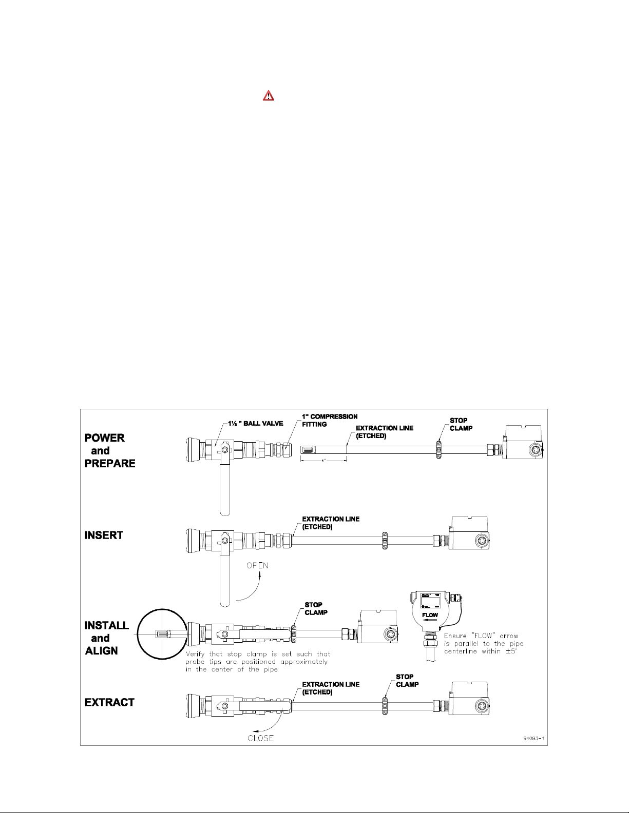
2.1.1.3 Installing/Removing Probe Instruments – refer to Figure 3
1. Power up your RheoVac MSP for at least 30 minutes before inserting probe into the
vent line ball valves. DO NOT leave probe in vent line without power or when
flooding the condenser.
2. Prepare each probe. Verify stop clamp location (see Figure 3). It is important that
the stop clamp is securely in place which determines the position of the multisensor assembly and ensures that the probes do not contact the opposite pipe wall.
Contact with the pipe wall could damage the probe. The clamp’s location is set at
the factory and is marked with a groove on each probe shaft. This location roughly
places the thermal mass flow elements (two metal probe tips) in the center of the
pipe. Refer to this mark if a stop clamp is inadvertently moved. Loosen the
compression nut on the thermocouple connector of the ball valve assembly and
clean the inner surface of the thermocouple connector to ensure it is free of particles
that may cause probe damage.
3. Insert probe until the extraction line meets the compression nut and snug the
compression nut.
4. Install each probe. When installing under vacuum, do not allow the clamp to
“slam” against the seal nut upon opening the valve. Grasp the probe firmly, with
hand against the seal nut, before opening the ball valve.
5. Align the FLOW arrow to the direction of flow and the centerline of the pipe.
6. When removing the probe, loosen the compression nut on the thermocouple
connector of the ball valve assembly and slowly extract the probe until the
Extraction Line is visible (see Figure 3). This indicates that the probe is clear of the
ball valve. Close the ball valve, then remove the probe from the assembly.
Figure 3: Installing and removing probe instruments
September 2013 9 © Intek, Inc. 2013
Revision D
Page 14

2.1.2 PT Probes
The PT probe(s) is installed through a ball valve similar to that shown in Figure 2 and Figure 3.
Special instructions, where applicable, are provided by Intek (see SECTION 8 - CUSTOM
INFORMATION).
2.1.3 Rheotherm CWFF Meters and Temperature Sensors
These instruments are installed by Intek Inc. or under Intek Inc.’s supervision. The installation
ensures proper seating/anchoring of the sensors in the selected locations. Wiring is fully coated using
epoxy coating that is proven for underwater application.
September 2013 10 © Intek, Inc. 2013
Revision D
Page 15

2.2 ELECTRICAL CONNECTIONS
A typical system with a model 950 RheoVac MSP is shown in Figure 4. Additional instruments
can be connected to the RS-485 bus per the EIA-485 standard.
Figure 4: Typical system configuration with one RheoVac MSP
IMPORTANT — Inspect and VERIFY these electrical connections carefully. Improper
connection could damage electronic components and sensor function. If additional holes need to be
drilled in the processor enclosure, remove the electronics subassembly (mounted on a mounting plate)
and temporarily store inside an ESD bag in a safe, clean place. Do not drill with electronics boards
inside the enclosure.
September 2013 11 © Intek, Inc. 2013
Revision D
Page 16

2.2.1 Main Electronics – contains the SCADA and HMI components
RS-232 CONFIGURATION
RS-422 CONFIGURATION
RJ-11 Pin Out
DB-9 Pin Out
RJ-11 Pin Out
DB-9 Pin Out
1
Tx (transmit)
1
N/C
1
Tx+ (transmit+)
1
Rx- (receive-)
2
N/C
2
Tx (transmit)
2
Tx- (transmitS)
2
Rx+ (receive+)
3
Rx (receive)
3
Rx (receive)
3
Rx+ (receive-)
3
Tx+ (transmit+)
4
N/C 4 N/C
4
Rx- (receive-)
4
N/C
5
Power (+5V)
5
Ground
5
Power (+5V)
5
Ground
6
Ground
6
Pulled high
6
Ground
6
Tx- (transmit-)
7
N/C 7 7 TBD
8
Pulled high 8 8 TBD
9
N/C 9 9 TBD
1. Transmitter(s) Power/COM: A DeviceNet 5711 cable is used all probe/sensor/4-20mA
transmitters. The color code for this cable is: RS-485 communications: white (A), blue
(B) and shield (SH); power: 24Vdc, red (+), and black ().
2. Main Power: Power connection wires should be at least 18 AWG. Connect main power
terminals to a dedicated 120 or 240 VAC, single phase, 15-amp circuit. A main power
switch is provided near the input power terminals.
3. Network Communication (Recommended): An Ethernet connection (RJ-45 style jack) is
provided. Intek recommends using this connection for all data transmissions because:
a. More measured data is accessible through the network connection.
b. Software and calibration file updates can be done remotely.
4. Serial Communication: Connector JP3 on the CPU interface PWA (printed wiring board
#08017-1) is the RS-232 and RS-422 serial communication interface. The configuration
information for a RJ-11 to DB-9 adapter is shown in Table 1 and Figure 5.
Table 1: RJ-11 to DB-9 Module Adapter
Figure 5: Serial communication interface
September 2013 12 © Intek, Inc. 2013
Revision D
Page 17

2.2.2 Satellite Electronics (only provided with systems that have several instruments)
1. Transmitter(s) Power/COM: A DeviceNet 5711 cable is used for RS485 communication
and power for all transmitters. The color code for this cable is: RS-485 communications:
white (A), blue (B) and shield (SH); power: 24Vdc, red (+), and black ().
2. Power: Power connection wires should be at least 18 AWG. Connect power terminals to a
dedicated 120 or 240 VAC, single phase, 15-amp circuit. A power switch is provided near
the input power terminals.
2.2.3 Distribution Box (see Figure 6) – For distributing RS485 communication and 24VDC
1. Connect the provided DeviceNet 5711 cable from the main processor unit to screw
terminal, JP1. The color code for this cable is: RS-485 communications: white (A), blue
(B) and shield (SH); power: 24Vdc, red (+), and black ().
2. Install ½" conduit between the distribution box and probes. Intek recommends 6 feet of
liquid-tight conduit between conduit and probes to minimize stress at the connector.
3. An adapter is provided which allows attachment of ½" flexible conduit to the connector.
4. Connect the probes to the distribution enclosure using the manufacturer supplied
DeviceNet 5711 cable to the screw terminals labeled JP3 to JP6 (refer to Figure 6).
5. For systems with multiple distribution boxes, screw terminal JP2 will be used to connect
to the JP1 screw terminal on the next distribution box in the series.
6. If no additional distribution boxes are used, ensure the outgoing termination resistor (JP7
or JP8) is enabled.
Figure 6: Distribution Box
September 2013 13 © Intek, Inc. 2013
Revision D
Page 18

2.2.4 4-20mA Transmitter Box (optional) – For driving eight (8) remote 4-20 mA analog
signals
The 4-20mA transmitter component is optional, see Figure 7. Note: Intek recommends using the
network connection for all data transmissions and communications with the RheoVac MSP.
1. Connect the DeviceNet 5711 cable. The color code for this cable is: RS-485
communications: white (A), blue (B) and shield (SH); power: 24Vdc, red (+), and black
().
2. Connect up to eight (8) signal wire pairs to the indicated terminals for isolated 4-20mA
outputs.
3. CMS 4-20mA transmitters are configured as active (transmitter sources the current) when
shipped. To change to the passive mode (receiver to source the current), extract each
small 4-20 board, find the JP1 pins, and move the two jumpers from the “Act” pins to the
“Pass” pins (two positions to the right of factory settings). Figure 8 shows the current
output circuit. Figure 8 also illustrates the active mode and the passive mode
configurations.
4. Refer to Section 4.1 for general information on standard transmitter channel-to-
instrument output mapping. Refer to SECTION 8 - CUSTOM INFORMATION for
transmitter channel-to-instrument 4-20mA outputs mapping.
Figure 7: Optional 4-20mA Transmitter Box
September 2013 14 © Intek, Inc. 2013
Revision D
Page 19

Q1
R1
75 Ohm
R1
75 Ohm
10 Ohm
R2
Q1
Vdd
Terminal
Isolated Circuit Isolated Circuit
from RheoVac Supply
Terminal
Active Configuration Passive Configuration
05026-1
CAUTION: Do not move config.
jumpers if instrument is powered.
RFL2N05
or Equiv.
RFL2N05
or Equiv.
Figure 8: 4-20 mA output circuit
September 2013 15 © Intek, Inc. 2013
Revision D
Page 20

2.2.5 RheoVac MSP and PT Probe Connector Assembly
1"
3/8"
1
2
3
CAUTION — Do not cross thread connection. The probe is supplied with a convenient plugin connector; the male side of the connector is installed in the probe junction box. The female side must
be installed onto the supplied DeviceNet™ type 5711 cable once it is run from the Distribution Box to
the probe. The wiring detail for the female plug-in connector (Turck p/n B4151-0/9) is shown in Figure
9. These connectors will use either the “backshell nut” or “conduit connector” depending on whether the
cable is installed in a liquid-tight conduit. When installing without conduit, use the backshell nut; when
using liquid-tight conduit, use the conduit connector with o-ring.
1. Slide all of the appropriate parts onto the cable as shown.
2. Strip the cable conductors as shown. The connector has 5 retention screws to hold the
wires in place. The use of crimp pins on the wires will greatly increase connection
reliability.
3. Loosen all 5 retention screws (do not completely remove).
4. Insert the wires, in accordance with color-coding shown (see Figure 9, insert).
5. Tighten the retention screws on each wire.
6. Reassemble the connector parts.
Figure 9: Probe connector assembly
September 2013 16 © Intek, Inc. 2013
Revision D
Page 21

2.2.6 Rheotherm CWFF Meters and Temperature Sensors Connections
These instruments are installed by Intek Inc. or under Intek Inc.’s supervision. Special
instructions, where applicable, are provided by Intek (see SECTION 8 - CUSTOM INFORMATION).
Electrical terminations, cable routing diagrams and more are provided in the CMS Installation
Instructions document.
September 2013 17 © Intek, Inc. 2013
Revision D
Page 22

SECTION 3 - USER INTERFACE AND DATA RETRIEVAL
This section presents the standard interface options and typical operations to retrieve data from
the system.
3.1 MENUS
The standard Main Electronics enclosure for the system serves as a SCADA RTU and HMI. The
standard enclosure has a 2x20 alphanumeric display and a 3-button access menu. Larger systems have a
standard LCD display and optional touch screen interfaces. Pressing all three buttons
(Left+Right+Enter) brings up the 3-button menu. The 3-button menu has the following selections:
Compress Data – Compresses data to the USB stick, if present, for data collection and transfer
Change Line Size – Change the line size of connected RheoVac MSPs. Typically, the factory
sets this to the specified line size on the order. If a probe is moved to a different location, the user
must check for line size and re-set this data as needed to ensure accurate measurement.
Shutdown – Provides option to Shutdown or Reboot the system
Cancel – Exit the 3-button menu
3.1.1 Compressing Data (to USB Stick)
The data stored in your CMS can be downloaded to a USB memory device, which is provided in
the instrument’s main electronics enclosure. Intek recommends having this USB stick disconnected from
the main electronics during normal operations. All the data is stored by the instrument on its internal
flash drive. Follow these steps when data needs to be retrieved and stored on the USB memory stick:
1. Insert the USB memory stick in the USB port, as shown. (Figure 10)
Figure 10: USB stick installation
2. On the front panel keypad, press all three buttons (Left+Right+Enter) at the same time and
release. Compress Data is the default selection, alternately, you can use the arrow keys and
Enter to navigate the menu. With Compress Data highlighted as shown in Figure 11 either wait
for the timer to reach zero or press enter to compress the entire CMS folder and save it to the
USB stick. No other user interaction is required. Figure 12 shows the screens that will follow as
data is compressed and copied to the USB memory stick.
September 2013 18 © Intek, Inc. 2013
Revision D
Page 23

LCD
Alphanumeric
LCD
Alphanumeric
Figure 11: 3-Button Menu with Compress Data Highlighted
Figure 12: Compressing and copying screens
3. The file saved to the USB stick is automatically named based on the date of the download. The
above example is shown in Figure 13.
Figure 13: D-drive explorer view of zip file
4. Copy the CMS_(serial number)_(MMDDYY).zip file to a computer for analysis. For data
plotting, tools are available at www.MyCondenser.com. For further support email data and
questions to techsupport@intekflow.com; a service contract or order may be required. The file
may also be uploaded to Intek’s server for review by Intek engineers. See Section 3.2 for
uploading instructions.
September 2013 19 © Intek, Inc. 2013
Revision D
Page 24

3.1.2 Change Line Size (i.e., pipe diameter)
LCD
Alphanumeric
LCD
Alphanumeric
The CMS instruments are configured at the factory for the line size specified. This is shown in
SECTION 8 - CUSTOM INFORMATION. If the probe is moved to a pipe with a different diameter
then it is important to change the line size so that the instrument will adjust the measured velocity and
report the correct volumetric flow rate. This is accomplished using the “Change Line Size” option.
The change line size menu can be accessed through the 3 button menu. Use Left and Right to
scroll through the options until Change Line Size is highlighted as shown in Figure 14. Then either wait
for the timer to expire or press Enter.
Figure 14: 3-Button menu with change line size highlighted
Left or Right - cycle between probes or line sizes depending on which one is selected.
Enter + Left or Enter + Right - switch whether Probes or Line Size is selected.
Left + Right - save and exit.
Left + Right + Enter - exit without saving.
The LCD screen is shown in Figure 15 and the 2x20 alphanumeric Select Probe and Select Line
Size options are shown in Figure 16.
Figure 15: Change line size LCD dialog
Figure 16: Change line size 2x20 alphanumeric menu
September 2013 20 © Intek, Inc. 2013
Revision D
Page 25

3.1.3 Shutdown
The Shutdown command can be accessed through the 3 button menu. Use left and right to scroll
through the options until Shutdown is highlighted. Then either wait for the timer to expire or press
enter. Then select either Shutdown, Reboot, or Cancel by pressing the enter button. A confirmation
message will appear, press enter to accept. If using the LCD, the main application window will close and
system diagnostics will run before the system reboots. If using the 2x20 alphanumeric, the screen will
display Rebooting until the diagnostic software starts. The entire reboot process should take less than
eight minutes to complete.
3.1.4 Cancel
The Cancel command can be accessed through the 3 button menu. Use left and right to scroll
through the options until Cancel is highlighted. Then either wait for the timer to expire or press enter.
Cancel will close the 3-button menu.
September 2013 21 © Intek, Inc. 2013
Revision D
Page 26

3.2 UPLOADING TO INTEK’S SECURE FTP SITE FOR DATA EVALUATION
The following instructions can be used to logon to Intek, Inc.’s Secure File Server to upload or
download software, files, pictures, etc. An account must first be set-up to permit secure file data transfer.
1. Open any internet browser, i.e., Internet Explorer, Mozilla Firefox, Google Chrome, etc. Type
http://sftp.intekflow.com into the address bar and hit enter. The following screens are shown
using Internet Explorer.
2. To access your Private folder, please use the User ID and Password when you registered and
set up your private account. Click the Login button.
3. Click OK at the Welcome screen.
4. To upload a file, click the Upload button at the bottom of the screen.
September 2013 22 © Intek, Inc. 2013
Revision D
Page 27

5. Browse to the file to upload, and then click the Upload button. Click the Close button when
finished.
6. For downloading, highlight (single left click) the file to download and click the Download
button at the bottom of the screen.
7. Click the Save button and select where to store the file.
8. When finished, click the Logout button at the top right of the screen.
September 2013 23 © Intek, Inc. 2013
Revision D
Page 28

SECTION 4 - COMMUNICATION METHODS
Address
Type
Description
20 – 3999
PT
Read 16 bit registers (“input registers”)
4000 – 7999
FM
Read 16 bit registers (“input registers”)
8000 – 11999
TC
Read 16 bit registers (“input registers”)
12000 – 15999
RV
Read 16 bit registers (“input registers”)
16000 – 19999
CC
Read 16 bit registers (“input registers”)
20000 – 23999
MA
Read 16 bit registers (“input registers”)
Address
Variable
Description
24 - 25
Temperature
Temperature measured by the first referenced PT Probe
The CMS system supports Modbus TCP (Modbus over Ethernet), RS232/422 serial Modbus and
OPC communication protocols. Analog 4-20mA outputs can be supplied as an option. Note: Intek
recommends using the network connection for all data transmissions and CMS communications.
4.1 ANALOG OUTPUT
All 4-20 mA output signals are linearly scaled such that 4 mA represents 0% of the rated full
scale value (except temperature, which is 0°C) and 20 mA represents 100% of the rated full scale value
(temperature is 100°C). See SECTION 8 - CUSTOM INFORMATION for custom outputs.
4.2 MODBUS
Modbus is a communication protocol that can be used to read process variables from the CMS
system. This section demonstrates the basics of Modbus communication with the CMS.
Registers - Modbus stores variables in memory locations referred to as registers. Modbus is
capable of storing variables as coils, discrete inputs, input registers, and holding registers. The CMS
conserves memory space by not supporting coils or discrete inputs. This creates more space for holding
and input registers whose type definition fits more closely with the CMS process variables. This
modification does not affect the formation of a Modbus request packet, which is demonstrated in the
packet section. However, if an attempt to poll the removed register banks is made a timeout error will
occur.
Table 2: CMS input registers
CMS process variables are stored as IEEE 751 floating point numbers unless specified otherwise.
Therefore, multiple registers must be used to account for the size of the floating point variables. Modbus
protocol specifies that multiple registers containing floating point values are transmitted with the most
significant byte of the register first.
Table 3: Multiple register example
September 2013 24 © Intek, Inc. 2013
Revision D
Page 29

Basic Function Codes - The Modbus packet structure is determined by the function code being
Function
Hex Code
Read Holding Registers
03
Read Input Registers
04
Read Exception Status
07
Write Multiple Registers
10
Write Holding Register
06
Code
Description
01
Invalid function code – function code not supported by device
02
Invalid data address – address defined by the start address and
number of registers is out of valid range
03
Invalid data value – number of registers = 0 or > 125
Type
Byte Length
Example
Device address
1 Byte (1 – 247)
0x01
Function code
1 Byte (Function code + 0x80)
0x83
Exception code
1 Byte
0x01
performed. Some of the basic commands that CMS supports are shown in Table 4.
Table 4: Modbus function codes
Exception Packet Definition - If an error is detected in one of the following packet definitions a
certain error code is applied and sent back in an exception response.
Table 5: Modbus error codes
Table 6: Modbus exception response
September 2013 25 © Intek, Inc. 2013
Revision D
Page 30

4.2.1 Modbus TCP
IP Layer
IP Header
Trailer
TCP Layer
TCP Header
Trailer
Modbus Layer
Modbus Packet
Modbus TCP is a way to communicate a Modbus packet over Ethernet. CMS implements a class
0 Modbus TCP communication standard. The CMS communicates Modbus TCP using port 502 with a
configurable IP address. Modbus TCP communication can be broken down into three different layers,
IP/Ethernet, TCP, and Modbus Protocol.
Table 7: Communication layers
The IP Header and Trailer dictate what IP address should receive the TCP Layer. The TCP layer
contains which port to establish communication and the transmitted data. The transmitted data is a
standard Modbus packet. There is no need for a slave address or CRC in Modbus TCP because these are
handled by the IP and TCP Layers. Modbus TCP also allows for specification of a unit identifier in the
Modbus Packet. The unit identifier functionality is not supported by CMS and should be defaulted to 1.
Connecting – To connect to the Modbus TCP server open any Modbus TCP client and enter the
IP address of the CMS system. CMS uses the standard Modbus TCP port of 502. Allow at least 5
seconds for the CMS to initialize the Modbus connection. The minimum poll rate supported by CMS is
1 second.
4.2.2 Serial Modbus
4.2.2.1 Modbus server global settings
A number of global settings are used to configure the CMS serial Modbus server. Many of these
settings can be adjusted by the end user to facilitate integration of a CMS with an existing Modbus
network. Table 8 lists the CMS serial Modbus global settings and their default values.
The settings can be modified in two ways: either by modifying a configuration file within the
CMS, (contact Intek for instructions), or by sending a properly formatted Modbus Function 06 message
to write the address listed in Table 8.
Process variables (PVs) for each instrument are produced by the CMS serial Modbus server.
These values take one of the two formats: multiplied integer or single float. The “Conversion Mode”
(Register 0009) setting listed in Table 8 determines the data format used for the PVs. In multiplied
integer mode, the CMS data values are multiplied by a power of ten specified in a set of additional
registers. The resulting values are then transmitted as 16-bit unsigned integers. In single float mode, all
of the data values are converted into a 4-byte hexadecimal string corresponding to their single-precision
float representation.
September 2013 26 © Intek, Inc. 2013
Revision D
Page 31

Table 8: Modbus server global settings
Address
Description
Allowed Values
Default
Format
Read Only?
0001
Restart Modbus Server
Write ‘1’ to restart
0
16-bit unsigned
No
0002
CMS Serial Port
Set to ‘0’ internally by
CMS System
0
16-bit unsigned
Yes
0003
Baud Rate
2400,4800,9600,14400,
19200 bps
9600
16-bit unsigned
No
0004
Data Bits
7 or 8
8
16-bit unsigned
No
0005
Stop Bits
0 = 1 stop bit
1 = 1.5 stop bits
2 – 2 stop bits
2
16-bit unsigned
No
0006
Parity
0 = No Parity
1 = Odd Parity
2 = Even Parity
3 = Mark Parity
4 = Space Parity
0
16-bit unsigned
No
0007
Modbus Address
1 – 255
1
16-bit unsigned
No
0008
Communication Mode
0 = RTU
1 = ASCII
0
16-bit unsigned
No
0009
Conversion Mode
0 = Multiplied Integer
1 = Single Float
1
16-bit unsigned
No
0010
Number of Probes
1 – 255
1
16-bit unsigned
Yes
Address
Description
Allowed Values
Default
Read Only?
8001
Multiplier power for TC1-1
0 – 3
16-bit unsigned
No
12005
Multiplier power for RheoVac MSP Actual Volume Flow
0 – 3
16-bit unsigned
No
12007
Multiplier power for RheoVac MSP Total Mass Flow
0 – 3
16-bit unsigned
No
12009
Multiplier power for RheoVac MSP Water Vapor Flow
0 – 3
16-bit unsigned
No
4.2.2.2 Modbus data settings (Multiplied Integer Mode)
The values listed in Table 9 are examples of how the Modbus server stores “Multiplied Integer”.
“Multiplied Integer” mode can be enabled by writing a “0” to register 09. The address for the multiplier
is the holding register equivalent of the input register parameter it is multiplying. These register values
determine the power of 10 that is used to multiply each parameter (effectively shifting the decimal point)
before it is transmitted as a 16-bit unsigned integer.
Table 9: Modbus example data holding registers
4.2.2.3 Modbus data registers (Multiplied Integer Mode)
When in Multiplied Integer Mode, the CMS data values are multiplied by a power of ten
specified in the registers listed in Table 9. The resulting values are then transmitted as 16-bit unsigned
integers. Each value therefore needs only 1 register (2 bytes) of allocated space. In this mode, the data
registers are allocated in pairs, with each data value followed by the multiplication power corresponding
to it. For example, assuming all multiplier registers are set to 3, the RheoVac MSP Pressure is
transmitted as follows:
RheoVac MSP Pressure (probe reading) = 1.257
Input Register 12011 (RheoVac MSP Pressure) = 1257
Holding Register 12011 (Multiplier Value) = 3
All other instruments can be calculated the same way substituting the correct address in place of
12011. The addresses for each instrument can be found in SECTION 8 - CUSTOM INFORMATION.
September 2013 27 © Intek, Inc. 2013
Revision D
Page 32

4.2.2.4 Modbus data registers (Single Float Mode)
In Single Float mode, all of the data values are converted into the 4-byte, big-endian
hexadecimal string corresponding to their single-precision float representation. The Modbus client
program must be capable of converting these 4-byte values back into single-precision float values. If the
client software is unable to make this conversion, the Multiplied Integer mode must be used. Data in the
Single Float mode is transmitted as follows:
RheoVac Pressure (probe reading) = 1.257
Single-Float Hex Representation = 0x3FA0E560
Input Register 12011 (high word) = 0x3FA0
Input Register 12012 (low word) = 0xE560
The full list of addresses for each MSP probe can be found in SECTION 8 - CUSTOM
INFORMATION.
4.2.3 Modifying the Modbus Configuration File
To modify the configuration file, the CMS must be attached to a local network. Once connected,
Windows Explorer can be used to browse into the CMS similar to a PC. Using the Network ID or IP
(see SECTION 8 - CUSTOM INFORMATION) of the CMS, the Modbus settings file can be found at
the following location:
\\<Network ID or IP of the CMS>\CMS\init\serial.ini
Figure 17 shows a sample serial.ini file. The Modbus settings are listed under the section titled
“[Modbus]”. The multiplied Integer settings can be found in the file MDBSInts.dat. The first column is
the starting register and the second is the power of 10. These values can be changed to fit the needs of
the existing serial Modbus network. Once the changes have been made and the file has been saved in its
current location, the CMS must be rebooted by simultaneously pushing all the keypad buttons to activate
the “Reboot System” function for the changes to take effect.
CAUTION: Modifying any of the other settings in this file could result in undesired behavior.
Figure 17: Sample serial.ini file
September 2013 28 © Intek, Inc. 2013
Revision D
Page 33

4.2.4 Modbus Troubleshooting
Problem
Cause
Solution
No response from CMS
1. System not set for Modbus
communication
2. Incorrect Modbus settings
3. Improper wiring
1. Verify settings in serial.ini file, see Table 8
2. Verify wiring connections
Not enough data
resolution in Multiplied
Integer mode
1. Non-optimal multiplier values set
1. Change the multiplier values in the
MDBSInts.dat file
Multiplier values are
changing
1. The CMS has overflow protection
built in. When [process
variable]*[multiplier value]
exceeds 65535, the instrument
automatically lowers the multiplier
value to retain a usable output.
1. Request the multiplier value along with process
data rather than hard coding the multiplier value
in the client software
2. Lower the multiplier value for each process
variable that reaches the overflow state
3. Use single precision float mode instead of
multiplied integer mode
September 2013 29 © Intek, Inc. 2013
Revision D
Page 34

4.3 OPC – (OLE for Process Control)
FM/12345-1/PV1/Label
Flow
FM/12345-1/PV1/Units
FPS
FM/12345-1/PV1/Value
21.4
CMS is equipped with an OPC data server which can publish its process variables across an
Ethernet network. The CMS software is compliant with OPC version 2.0. When using OPC we
recommend the use of a NTP network time server to ensure the CMS time is synchronized with the
client system.
4.3.1 Connecting
The following information can be used to connect and view the process variables using an OPC
Client. Please be sure to properly configure any firewall to allow OPC communication.
OPC Server Name = OPC_Intek-exe
Remote Machine Name = <CMS IP> or <CMS Network Name>
Client DCOM Settings
Authentication Level: None
Impersonation Level: Identify
Security: Default
4.3.2 Adding Process Variables
Once connected to the CMS system there will be a tree view of the available process variables
organized by instrument type. Select or expand the type of instrument you would like to view outputs
from (FM, PT, RV, TC, MA, etc). Then select or expand the specific instrument you would like to
monitor. Each instrument contains at least one process variable denoted by PV#. PV# will then have a
series of sub values either Label, Units, and/or Value depending on the instrument type. These sub
values can be added to a group or viewed individually to get the current outputs of the desired
instrument. Other variable options are available and vary by client. Please consult your OPC client
manual for more specific settings.
A flow meter (FM) outputs two process variables marked as PV1 and PV2. An example to view
the current information for PV1 flow meter 12345-1 is shown in Table 10. A complete list of all OPC
published variables can be found in SECTION 8 - CUSTOM INFORMATION.
Table 10: Process variable example
September 2013 30 © Intek, Inc. 2013
Revision D
Page 35

SECTION 5 - TROUBLESHOOTING
MESSAGE CODE
Description/Symptom
PROBABLE CAUSE
ACTION
OUTPUT ERROR
CODES
Global Message Codes
MSG-0
Communications not
being received from
probe(s)
1. Improper cable hookup
2. Blown main fuse
3. Failed RS-485 circuit
4. Damaged flow sensor
1. Verify plug-in connector is
properly mated
2. Check F1 fuse on probe board
3. Check all cable connections
4. Contact factory
-99
MSG-1
Invalid data received
from probe(s)
1. Failed RS-485
communications component
1. Check wiring
2. Contact factory
N/A
RheoVac MSP Messages Codes
MSG-2
Flow sensor heater
“OFF”
1. Blown heater fuse
2. Failed electronic component
1. Contact factory
N/A
MSG-3
RS sensor power
“OFF”
1. Probe temperature too high
2. Liquid water on probe tips
1. Check that probe temperature is
<160°F
2. Contact factory
N/A
MSG-4
RS heater “OFF”
1. Component failure
1. Contact factory
N/A
MSG-5
Circuit issue
1. Problem with circuitry
1. Contact factory
N/A
MSG-6
Temperature alarm
(above 210°F/99°C)
1. Steam in exhaust pipe
1. Remove probe or cool line
ASAP!
2. Once line has cooled down and
probe is reinstalled, check unit
for proper function
N/A
MSG-7
Wet probe
1. Liquid water on probe tip
1. Remove probe ASAP!
2. Contact factory
N/A
MSG-8
RS sensor problem
1. RS sensor problem
1. Remove from line, allow 24 hrs
with power on to dry out RS
sensor, reinsert probe
2. Contact factory
N/A
MSG-9 or (CalX)
Calibration expired
1. Probe calibration is expired
1. Contact factory for recalibration
N/A
Mass flow output
saturates high, will not
respond to flow changes
1. Flow rate is not within range
of calibration
2. Blown heater fuse
3. Failed electronic component
1. Contact factory about re-ranging
instrument
2. Contact factory
N/A
Mass flow output
saturates low, will not
respond to flow changes
1. Flow rate is not within range
of calibration
2. Failed electronic component
1. Contact factory about re-ranging
instrument
2. Contact factory
N/A
The CMS will identify problems by alternately flashing a message code and the serial number of
the instrument affected. Table 11 provides a guide to identify causes of problems and determine
appropriate actions to resolve the observed problems. If problems are encountered and factory assistance
is desired, please contact the factory.
Table 11: Troubleshooting/message code guide (diagnostic messages)
September 2013 31 © Intek, Inc. 2013
Revision D
Page 36

MESSAGE CODE
Description/Symptom
PROBABLE CAUSE
ACTION
OUTPUT ERROR
CODES
PT Probe Message Codes
MSG-2
Reserved
MSG-3
Reserved
MSG-4
Reserved
MSG-5 or (CalX)
Calibration Expired
1. Probe Calibration Expired
1. Contact factory for
Recalibration
N/A
Flow Meter Message Codes
MSG-2
Reserved
MSG-3
Reserved
MSG-4
Reserved
MSG-5
Sensor Issue
1. No sensor communication
2. Irregular sensor data
1. Contact factory
-101
Thermocouple Message Codes
Open
TC Circuit Open
1. Loose connection
2. Broken wire
1. Check wiring at the electronics
2. Contact factory
-500
Under
TC Value Under Range
1. Temperature below 32°F
1. Contact factory
-501
Over
TC Value Over Range
1. Temperature above 212°F
1. Contact factory
-502
Error
General Error
1. Loose connection
2. Component failure
1. Check wiring at the electronics
2. Contact factory
-504
MA (4-20mA DAQ) Message Codes
Open
MA Circuit Open
1. Loose connection
2. Broken wire
1. Check wiring at the electronics
2. Contact factory
-500
Under
MA Value Under Range
1. Output below range
1. Contact factory
-501
Over
MA Value Over Range
1. Output above range
2. Contact factory
-502
Error
General Error
1. Loose connection
2. Component failure
1. Check wiring at the electronics
2. Contact factory
-504
September 2013 32 © Intek, Inc. 2013
Revision D
Page 37

5.1 COMMON ISSUES
Modbus/OPC client loses communication on/after midnight
The CMS system is designed to perform an automatic daily maintenance reboot. It takes
approximately 5-8 minutes for the system to return to normal operation. We recommend that digital
communication clients use an extended timeout value of 8 minutes or greater to prevent midnight reboot
timeouts.
Modbus/OPC data is not updating
The digital outputs update once every minute. Requesting data faster than one minute will result
in duplicate data points. Intek recommends setting the poll or scan rate of data acquisition system to one
minute.
September 2013 33 © Intek, Inc. 2013
Revision D
Page 38

SECTION 6 - MAINTENANCE GUIDE
This section provides a guide for typical operations interaction with the components of the CMS.
6.1 WATERBOX INSTRUMENTS
Intek recommends, at a minimum, annual inspection of the CWFF meter IDs and integrity
of the coatings. CMS instruments are installed into cooling water systems that have widely varying
debris controls and water chemistry controls. It is important to schedule maintenance inspections of the
CWFF meter IDs and integrity of the coatings. It may be convenient to conduct these inspections at the
same time as regular waterbox cleanings.
The CWFF meters should be cleaned during each waterbox cleaning. A wet standard bottle brush
can be used to remove mud and dirt. If scale is present then acetic acid (vinegar) can be used with the
bottle brush to remove the scale. Thoroughly flush with fresh water after cleaning, do not allow acetic
acid to remain in tubes. Never use abrasive tools to clean the meters.
If repair of coating/recoating is necessary, ensure that the surface to be coated is thoroughly
cleaned using appropriate means for removing dirt, grease and debris in accordance with coating
manufacturer’s recommendations. Apply repair coating in accordance with manufacturer’s
recommendations.
Intek offers services to repair, recoat and clean waterbox instruments.
6.2 CALIBRATION
All instruments are calibrated at the factory using NIST traceable standards. The waterbox
sensors can be checked in the field and adjusted with factory equipment. RheoVac vent line condenser
and air in-leak monitors can only be calibrated at the factory. Recommended recalibration schedule is
every 2 years for all instruments. The CMS user interface and calibration files can be updated via
uploads from a USB memory device. Contact the factory for details at (614) 895-0301 or
techsupport@intekflow.com.
6.3 SOFTWARE UPDATES
CMS systems are custom configured for the end user’s system and intended purpose. Display
changes, computation changes, calibration updates and general software updates are readily
accomplished using USB file transfers. For specific instructions along with software updates, contact the
factory for details at (614) 895-0301 or techsupport@intekflow.com.
6.4 ADDING/REPLACING SENSORS/INSTRUMENTS
The CMS delivers 24V to power instrument electronics and RS-485 for instrument
communication. Flow, pressure, temperature, humidity/dew point and multi-sensor instruments can be
added to the system if desired. Contact the factory for specifics at (614) 895-0301, or
sales@intekflow.com.
September 2013 34 © Intek, Inc. 2013
Revision D
Page 39

SECTION 7 - CUSTOMER SERVICE
Intek’s corporate philosophy is to help solve our customers’ difficult flow measurement
problems. When you purchase a CMS system you also receive Intek’s dedicated customer service. For
sales or product service, call your local representative or Intek directly at (614) 895-0301 8AM to 5PM
EST/EDT weekdays or fax us anytime at (614) 895-0319. E-mail inquiries should be sent to
sales@intekflow.com or techsupport@intekflow.com. Our customer service staff will provide assistance
promptly. To allow us to help you more efficiently, please have the complete serial number of the
equipment available.
7.1 TROUBLESHOOTING
If you have reviewed SECTION 5 TROUBLESHOOTING and have questions, please call our
experienced engineers for assistance. In many cases we can solve a problem over the phone. Please
provide as complete a description as possible of the problems encountered.
7.2 FACTORY AND FIELD SERVICE
If you request field service to help with condenser performance problems, Intek has, for a fee,
experienced engineers who can be assigned to meet your needs. For CMS instrument related questions,
if a problem cannot be solved over the phone, with your help, we will help you to determine if factory
service or field service will be the best solution.
To request factory service on your instrument, a Return Material Authorization (RMA) and
purchase order is required. Our customer service staff will assist you with the required information to
return equipment for service. Use reasonable care in handling the RheoVac and PT probes. Do not bend
the probes, damage the tips, or obstruct the sensing ports. If moving the unit, make sure the probe is
adequately protected from foreign objects and damage during handling. When returning
instruments/probes for factory service, be sure to carefully pack the instrument/electronics; extra care
should be taken to protect the probes from damage in shipment. When possible, use the factory supplied
PVC probe protection tube and custom shipping box for MSP and PT probes.
7.3 CONSULTING SERVICES
Intek has developed unique solutions for plants experiencing problems with dissolved oxygen,
heat rate and excessive backpressure. We provide comprehensive condenser diagnostic and analysis
services. Plant and CMS data can be transmitted to Intek for analysis and results are provided via
electronic means or hard copy reports. Please call us to discuss your observations, concerns, and needs.
Intek has many years of experience helping customers solve their complex condenser problems.
Intek's monitoring services ensure plants have expert assistance with collecting, interpreting, and
reporting on condenser operations. In many cases, excess backpressure problems can be predicted before
they have a limiting effect on power production. Contact your Intek sales team for a quotation to meet
your specific needs, sales@intekflow.com.
For information on Intek’s power plant instruments and services, such as a new CMS system,
liquid or gas flow meter or flow switches, circulating water flow and fouling meters or condenser
inspection, analysis, or monitoring services, contact the Intek technical sales department by
phone/fax/email. Our staff will be pleased to answer all questions and provide information on our
recommended solutions, instruments, or services, sales@intekflow.com.
September 2013 35 © Intek, Inc. 2013
Revision D
Page 40

7.4 CONDENSER MANAGEMENT AND RheoVac/CMS TRAINING
Intek conducts Condenser Operations and Management workshops to educate professionals on
RheoVac and Rheotherm instrumentation as well as condenser operations and fundamentals. At these
workshops, degraded condenser performance is discussed including root cause analysis for poor
performance and condensate chemistry issues. Approaches to diagnose problems and develop solutions
are presented and discussed.
Several training tools and reference materials can be found on our website,
www.MyCondenser.com. Tutorials can be found in the help menu, included are presentations on
condenser theory, instrumentation, case studies, and services offered by Intek. Posted case studies show
events and conditions captured by the RheoVac MSP condenser monitoring instruments and how the
instrument helped troubleshoot or solve upset conditions. Case studies include information on pump
issues, air in-leakage events, steam jet air ejector problems, and general condenser performance
troubleshooting. Case studies captured by the Rheotherm Circulating Water Flow and Fouling Meters
are also presented and discussed. Macrofouling, thermal stratification, circulating water pump
degradation, and identification of condenser design deficiencies are highlighted.
September 2013 36 © Intek, Inc. 2013
Revision D
Page 41

SECTION 8 - CUSTOM INFORMATION
This section contains information unique to the system delivered to the customer. It contains a
record of the system components, information important to the installation of equipment and setup of
data communication.
8.1 UNIT IDENTIFICATION AND CONFIGURATION
Model no.:
Serial no.:
Customer identification:
The marked (X) items denote the configuration of this unit as originally shipped from the factory.
Input Power: 100-250 VAC, 50/60 Hz
Outputs:
Digital: Ethernet Modbus
Serial Modbus
OPC
Time Server IP:
Analog: 4-20mA Output (see Section 4.1)
Wireless: WiFi Transmitter
Tablet HMI: CMS Manual and condenser documents in:
(See tablet manual for special information and instructions)
Data Access:
Ethernet Network ID:
Ethernet IP:
Portable Data Storage: Portable USB Data Storage Device
Enclosures: Cables:
Main Electronics Box: DeviceNet 5711 Cable (RS485):
Satellite Electronics Box: Cat5 Ethernet X-Over Cable - 10 ft
Distribution Box:
4-20mA Transmitter Box:
Ball Valve Assemblies: 1 ½" ball valve assembly:
Software: Windows OS; CMS system software version :
Summary of instruments included in this system:
Rheotherm CWFF: Tube size: Sch:
RheoVac Multi-Sensor Probes: Pipe size: Sch:
PT Probes:
Temperature Instruments:
MA Instruments:
P Instruments:
Other:
September 2013 37 © Intek, Inc. 2013
Revision D
Page 42

8.2 SPECIAL INFORMATION
Below is a list of special information, attached to this document, which is relevant to customer
specific equipment.
System configuration/layout recommendations
High temperature RheoVac MSP installation instructions
Wireless tablet manual
Special information included
MODBUS register definition, example value(s) and units list
OPC register definition, example value(s) and units list
4-20mA channel definition, example value(s) and units list
Drawings of custom enclosures
Custom system wiring diagrams
Important Information has been reviewed with the customer and is included in this manual.
Engineering: Date:
Sales: Date:
September 2013 38 © Intek, Inc. 2013
Revision D
 Loading...