

Page 1

TABLE OF CONTENTS
SECTION 1 — GENERAL INFORMATION .................................................................... 1
1.1 INTEK’S POWER INDUSTRY SERVICES................................................................. 1
1.2 INTRODUCTION .......................................................................................................... 2
1.3 PRINCIPLE OF OPERATION....................................................................................... 3
1.4 TECHNICAL SPECIFICATIONS ................................................................................. 3
1.5 PRECAUTIONS AND RECOMMENDATIONS.......................................................... 4
SECTION 2 — INSTALLATION........................................................................................ 5
2.1 RHEOVAC SYSTEM INSTALLATION/SITE SELECTION .......................................... 5
2.2 PROBE INSTALLATION.............................................................................................. 7
2.3 ELECTRICAL CONNECTIONS................................................................................... 8
SECTION 3 — OPERATION ............................................................................................ 15
3.1 SYSTEM START-UP................................................................................................... 15
3.2 PORTABLE USB DATA STORAGE/WARRANTY REGISTRATION INSTRUCTIONS ..... 15
3.3 DISPLAY......................................................................................................................15
3.4 COMMUNICATIONS ................................................................................................. 16
3.5 DATA PROCESSING .................................................................................................. 16
3.6 CUSTOM SOFTWARE ............................................................................................... 18
SECTION 4 — MAINTENANCE...................................................................................... 19
4.1 CALIBRATION ........................................................................................................... 19
4.2 SPARE PARTS............................................................................................................. 19
4.3 TROUBLESHOOTING................................................................................................ 20
4.4 HARDWARE/SOFTWARE MODIFICATIONS AND UPDATES............................ 22
SECTION 5 — CUSTOMER SERVICE FROM THE CONDENSER EXPERTS ...... 23
5.1 QUESTIONS ON EXISTING HARDWARE .............................................................. 23
5.2 TROUBLESHOOTING................................................................................................ 23
5.3 FACTORY AND FIELD SERVICE ............................................................................ 23
5.4 NEW EQUIPMENT AND SERVICES ........................................................................ 23
5.5 CONDENSER MANAGEMENT AND RHEOVAC TRAINING .................................. 24
SECTION 6 — CUSTOM INFORMATION .................................................................... 25
6.1 UNIT IDENTIFICATION............................................................................................ 25
6.2 CONFIGURATION...................................................................................................... 25
6.3 SPECIAL INSTRUCTIONS ........................................................................................ 25
Appendix A - RheoVac Model 950 User Interface Software
Appendix B - RheoVac Model 950 Networking
Appendix C – New Features and Options for the RheoVac Model 950
I:\OFFICE\WPMANUAL\RV950A Rev New.doc
Manual no. RV950A Rev. –
©Intek, Inc. 2010
Page 2

WARRANTY
Intek, Inc. warrants each RheoVac product to be free from defects
in material and workmanship under normal use and service, Intek's
obligation under this warranty being limited to making good any
part or parts thereof which shall, within one (1) year after delivery
of such product to the original purchaser, be returned to Intek with
transportation charges prepaid and which Intek's examination shall
disclose to its satisfaction to have been thus defective; this
warranty being expressly in lieu of all other warranties, express or
implied and all other obligation or liabilities on Intek's part. The
purchaser will assume all responsibility and expense for removal,
decontamination and reinstallation of equipment.
RheoVac instruments are manufactured under United States patent
numbers 4,255,968, 5,485,754, 5,752,411 and 6,526,755. Intek,
Rheotherm and RheoVac are registered trademarks of Intek, Inc.
Windows is a registered trademark of Microsoft Corporation in the United States and other countries.
Intek, Inc.
751 Intek Way
Westerville, Ohio 43082-9057
Phone (614) 895-0301 – Fax (614) 895-0319
web site – www.intekflow.com
e-mail – techsupport@intekflow.com
Page 3

SECTION 1 — GENERAL INFORMATION
1.1 INTEK’S POWER INDUSTRY SERVICES
Intek manufactures RheoVac condenser and air in-leak monitor Rheotherm circulating water
flow and fouling meters, flow meters, flow switches, as well as, temperature sensors and pressure
probes. These specialty instruments for the power industry provide continuous monitoring of
critical parameters that have historically been unavailable or inadequately measured since steam
surface condensers were introduced.
The data from these instruments have been used to gain a unique comprehensive understanding
of steam surface condensers and the condensation process. This understanding has enabled us to
help customers troubleshoot condensers with greater speed and accuracy than ever before. We
have expanded our service offerings by developing an online diagnostic toolkit for steam surface
condensers, available at www.MyCondenser.com.
We have also taken advantage of our aerospace design tools and design expertise for the purpose
of designing condenser retrofits for performance and condensate chemistry improvement. Intek
has lead condenser retrofitting projects that have transformed underperforming condensers into
some of the best performing condensers in the world.
The condenser services team under Dr. Joseph Harpster’s leadership has also sought to educate
the industry by contributing volumes of material to ASME and EPRI regarding proper condenser
measurement and steam flow dynamics. Intek also teaches a semiannual Condenser Operations
and Management Workshop accredited by The Ohio State University for Continuing Education
Credit. Tutorials and case studies are also available at www.MyCondenser.com.
Intek is The Gateway to Improved Condenser Performance, Fast Response Maintenance
and Optimized Operations. Thank you for your interest in Intek's Power Industry
Instruments and Services.
- 1 -
Page 4
1.2 INTRODUCTION
RheoVac technology provides direct measurement of all necessary properties of the gases, in the
condenser exhauster line, to give an accurate determination of air in-leakage and condenser
performance related parameters. The RheoVac instrument is a part of Intek's services that
provide the power industry with the most advantageous and complete measurement and
diagnostic tools for condenser systems. Other measurement instruments offered by Intek include
circulating water flow and fouling meters, flow meters, flow switches, condenser shell pressure
and temperature sensors.
the RheoVac®System*
*USPNs 4,255,648; 5,485,754; 5,752,411; 6,526,755
A model 950 RheoVac system consists of single or multiple probes reporting to a central signal
conditioner and processor unit. The sensing probes, consisting of multiple sensors, are installed
in the vacuum line between the condenser and the exhauster. The sensor assembly employs the
patented Rheotherm
temperature, pressure and water vapor relative saturation measurements are made using high
accuracy platinum resistance temperature detectors (RTD), strain gauge pressure sensor and
specially configured and calibrated water vapor saturation sensor.
®
technology to provide an accurate mass flow measurement. Additionally,
Figure 1 RheoVac Model 950
- 2 -
Page 5

1.3 PRINCIPLE OF OPERATION
The Rheotherm flow sensor is calibrated to measure the total mass flow of the gaseous water
vapor/air mixture. From the other three measurements, the RheoVac electronics converts the
total gas mass flow signal from the probe into two components, air mass flow rate and water
vapor mass flow rate.
The RheoVac system is fully calibrated at the factory under dynamic fluid conditions identical to
those within the power plant vacuum line. Field adjustments are not required, with the exception
of line size.
1.4 TECHNICAL SPECIFICATIONS
1.4.1 Sensor (Probe) Specifications
Primary Calibration Accuracy:
±5% of total mass flow
Repeatability:
±0.5% of reading
Operating Temperature:
Electronics: 40 to 120ºF (5 to 49ºC)
Probe: 40 to 160ºF (5 to 71ºC)
Never subject probe to temperatures above 210ºF (99ºC)
Operating Pressure:
0.5 to 10 inches Hg absolute
15 psi maximum
Storage Temperature:
-20 to 210ºF (-29 to 99ºC)
Storage Pressure:
15 psig (maximum)
Process Connection:
Hot tap assembly
(1½” thread-o-let must be welded to pipe for hot tap installation)
Wetted Surface:
300 Series SS and engineered plastic
1.4.2 Main Electronics (Remote or PC) Signal & Data Access
Local Display:
Back-lit LCD
Selectable display of air in-leakage and 6 additional instrument output parameters
Parameter scrolling
Metric/English units
Input Power:
100-250 Vac, 50/60 Hz
Signal Output or Data Access:
RS-232/RS-422/Serial Modbus, Ethernet, TCP/IP
Eight 4-20mA signals (optional)
Wireless (Optional)
OPC (Optional)
Temperature Environment:
Operating: 40 to 120°F (5 to 49°C)
Storage: -20 to 210°F (-29 to 99°C)
- 3 -
Page 6

1.5 PRECAUTIONS AND RECOMMENDATIONS
x Read the entire manual before installing and operating the RheoVac system.
x WARNING — Be sure to power up your RheoVac instrument system and probe(s)
for at least 30 minutes before inserting probes into the vent line hot taps. DO NOT
leave probe in vent line without power or when flooding the condenser.
x Carefully select the best locations for installation of the probes. Access, orientation,
installation clearances, freedom from standing water, absence of water traps, minimum
required straight-run should all be considered when selecting a probe location.
x Use reasonable care in handling the probe — the sensing components are delicate. Do
not bend the probes, damage the tips, or obstruct the sensing ports. If shipping the unit,
make sure the probe is adequately protected from foreign objects and damage; save and
reuse factory provided custom probe protector and shipping boxes.
x Use proper input power — it must be between 100 and 250 Vac (nominal 120/240 Vac)
at 50/60 Hz (60 Hz nominal).
x Confirm the line and environmental temperature is always within the probe and
electronics ratings — never operate a probe at or subject it to temperatures or pressures
beyond its specified limits. (See SECTION 1.4)
x WARNING — Never allow live high temperature steam to flow either direction in
the exhauster line where a probe is located. This can happen if steam jet ejectors
are operated incorrectly.
x WARNING — Do not allow the instrument sensors (or separate RS probe) to come
into contact with liquid water, including water from condenser flooding (hydro
testing) and entrained liquid water — entrained liquid water is an indicator of poor
condenser venting and may be present in your condenser vent line due to design
configuration. See EPRI’s “Air In-Leakage and Intrusion Prevention Guideline,”
TR 1014125. Intek provides analysis and design services to improve condenser
venting and reduce or eliminate entrained liquid water and excess condenser back
pressure.
x Keep moisture out of the enclosures — once all service connections are made, make sure
all gaskets are in place and the enclosure lids are tightly closed. Seal all conduit lines.
x Intek recommends using the RJ-45 network connection for all data traffic (as opposed to
serial and 4-20 mA communication).
x Intek recommends a service contract to ensure probes are within calibration
specifications and electronics are maintained with appropriate software/hardware
updates. Instrument probes should be returned to the factory for inspection and
calibration service every two years.
x Intek recommends the use of condenser diagnostic tools and tutorials provided on
www.MyCondenser.com
.
- 4 -
Page 7

SECTION 2 — INSTALLATION
These instructions are general guidelines for the installation of RheoVac instruments in their
standard configuration. Additional information pertaining to your unit is covered in SECTION 6
— CUSTOM INFORMATION. Carefully read these instructions prior to installing the equipment. Also, see preceding SECTION 1.5; PRECAUTIONS AND RECOMMENDATIONS.
2.1 RheoVac SYSTEM INSTALLATION/SITE SELECTION
The standard RheoVac 950 can be configured with one, two or three probes. A three probe
system is intended to be installed so that one probe is in each of the two exhaust lines coming out
of the condenser (A side and B side). The third probe should go in the header pipe that runs to
the exhauster(s). Other installation arrangements of multiple probes should be discussed with the
factory. High temperature dual probe systems (where each “probe” is comprised of a matched
main FTP probe and an RS probe pair) have different configuration limitations for a given
RheoVac 950 system.
2.1.1 Probe Site Selection
x The location for each probe should be selected so as to provide the probe sensing area
with well-established mean flow velocity, uniform system temperature and pressure, and
consistent non-liquid phase flow medium. Pipe sections ahead of a probe, in which water
can accumulate, must be avoided. Refer to Figure 2 and select the most preferred
location for each probe. Do not install the probes beyond any “trap” sections as shown in
Figure 2, Configurations B and D. Special installation instructions unique to your unit,
where applicable, will be noted in SECTION 6.3 SPECIAL INSTRUCTIONS. Refer to
this section now to review special instructions.
RheoVac
INSERTION RECOMMENDATION
PROBE
Figure 2 RheoVac Probe Insertion Recommendation
- 5 -
Page 8
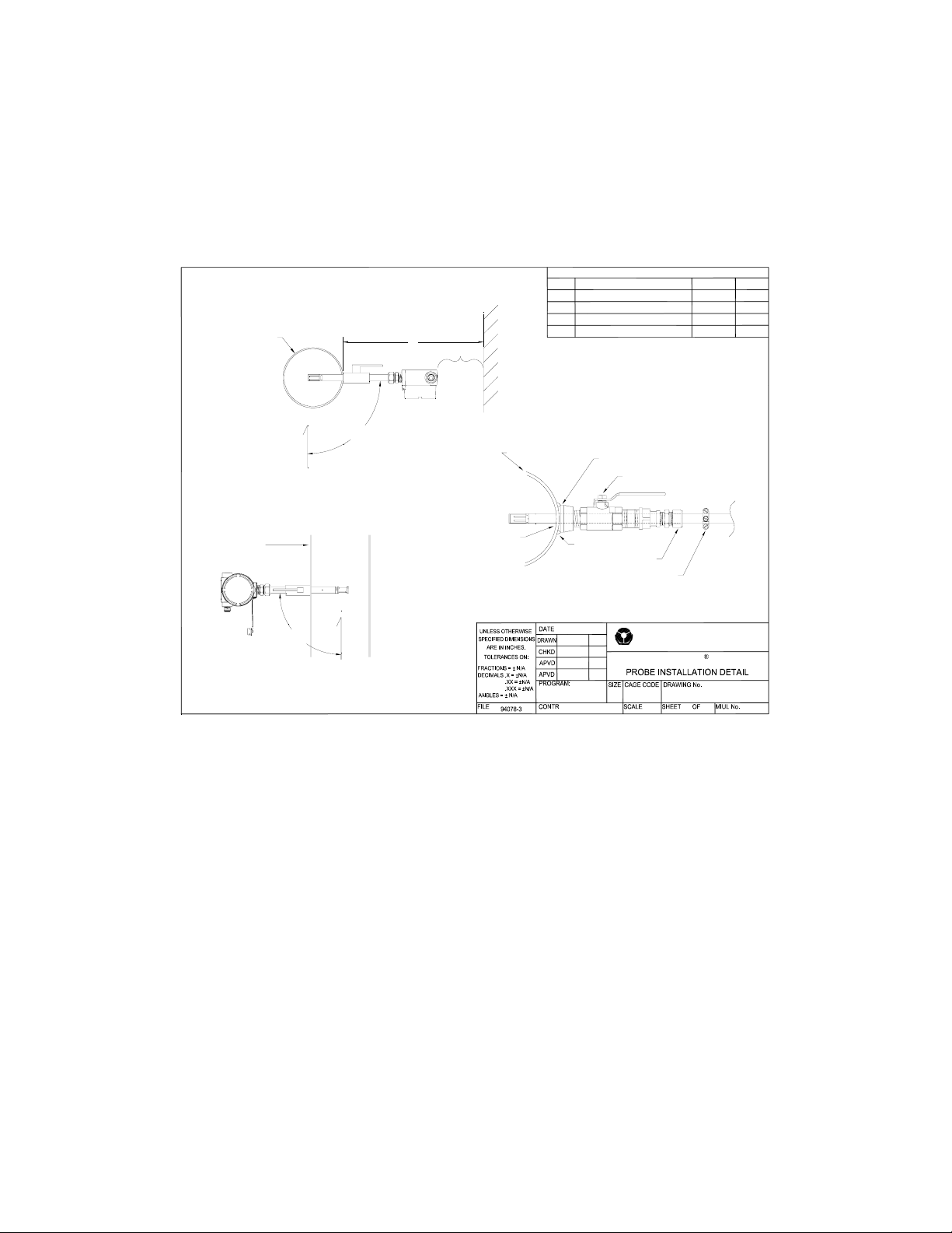
x Check installation clearance. Each transducer probe is approximately 3 feet (0.9m) long
and the hot tap assembly is approximately 13 inches (0.33m) long, therefore, allow
minimum clearance of 4 feet (1.3m) for probe installation. Be sure there are no
obstructions around the vacuum line that will interfere with probe insertion. Figure 3
shows the proper insertion angle. THIS ORIENTATION IS IMPORTANT FOR
PROPER OPERATION.
VACUUM PIPE WALL
VACUUM PIPE WALL
PROBE SHOULD BE
PARALLEL TO FLOOR
REQUIRED INSTALLATION ANGLE
FOR HORIZONTAL PIPE RUN
PROBE SHOULD BE
PARALLEL TO FLOOR
+0°
90°
UP
REQUIRED INSTALLATION ANGLE
FOR VERTICAL PIPE RUN
+0°
90°
-5°
-5°
UP
4'
CLEAR SPACE
1 1/2" THRU HOLE
REV DESCRIPTION DATE APV D
A EDITING CHANGES 11/18/97
Changed installation angleB 11/15/99
Edited Hot Tap Installation
C
Changed Probe Box
D
RHEOVAC HOT TAP INSTALLATION
VACUUM PIPE WALL
WELD
COMPRESSION FITTING
STOP CLAMP (ON PROBE)
10/03/95
JVR
REVISIONS
1 1/2" FNPT THREAD-O-LET
1 1/2" BALL VALVE
Intek, Inc.
751 Intek Way
Westerville, Ohio 43082
A
59936
NTS
RheoVac
94078-3
1 1
12/04/00
12/04/07
MH
BC
BC
BH
Figure 3 Transducer Installation Detail
x It is recommended that only Intek supplied hot taps be used. The hot tap length affects
the insertion depth of the probe and must be accounted for; likewise, the proper port
clearance for the probe’s maximum diameter.
x Observe the selected sites; check for ease of access. They should be convenient for the
removal and replacement of probes at any time for service without ladders, building
scaffolding or waiting for plant shutdown.
x Check operating conditions. The temperature and pressure limits (see TECHNICAL
SPECIFICATIONS; SECTION 1.4) of the unit should be checked to ensure compatibility
with your application.
x Gases in the air removal line should be free of liquid water, mist or fog. Wetness in the
line will result in erroneous readings from the instrument and can damage sensors. If wet
conditions exist in the air removal line, there is either air removal section damage or
design flaws which adversely affect condenser performance. Consult Intek for assistance
in evaluating the severity of the problem and possible remedies.
- 6 -
Page 9

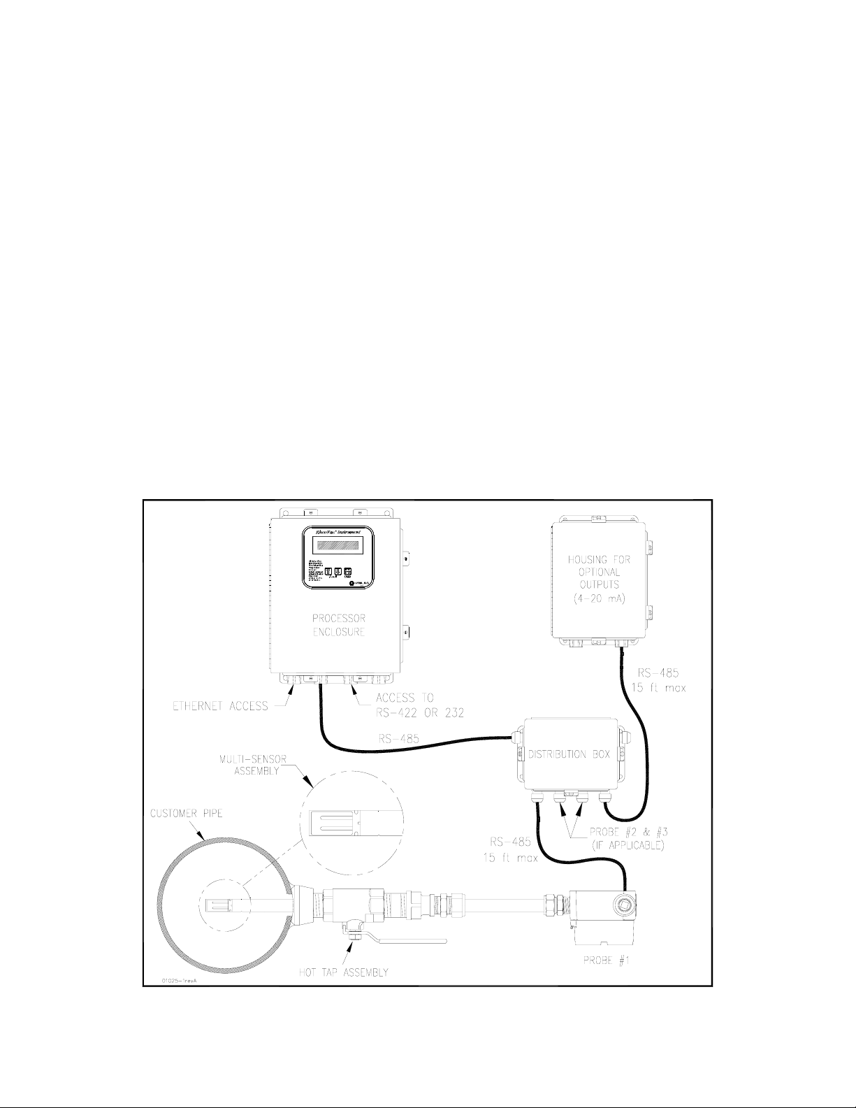
2.1.2 Electronics Unit Site Selection
The Model 950 typically has two or three electronics enclosures (see Figure 1). The processor
enclosure and other electronics boxes should be installed in a convenient location and should be
kept away from direct sources of heat, such as non-insulated steam lines, or moisture. The
maximum temperature rating of electronics is 120(F; ensure that this temperature will not be
exceeded inside the enclosure. Once the wiring connections are made, close and latch down the
box lid to protect the contents from damage and debris. All these enclosures should be located in
a dry area and should be kept clamped shut during normal operation. Do not allow water to get
into the enclosures. If installed outdoors, build a roof over all enclosures to prevent potential
water infiltration.
x Processor Enclosure: This 12x10 NEMA 4 enclosure houses the display and central
processing unit. Input power (100-250 Vac, 50/60 Hz) is connected inside this enclosure.
x Distribution Box: This 8x6 NEMA 4 enclosure is typically located near the probe that is
closest to the processor enclosure unit. It is connected to the main processor with an RS485 bus DeviceNet™ cable, which can be hundreds of feet long. The probe and
transmitter RS-485 cable connections are also made within this box. The probe and
transmitter cable lengths should be 15 ft or less.
x Transmitter Box (optional): This 10x8 NEMA 4 enclosure contains terminals for
accessing the eight 4-20mA signals. It can be located in or near the control room so that
the 4-20 wires do not have to be run from the plant floor. An RS-485 DeviceNet™ cable
runs from the distribution box to the transmitter box. (There are restrictions on how this
can be done, so check manual SECTION 6, or contact the factory.)
2.2 PROBE INSTALLATION
A. Hot Tap Installation
1. Check hardware. Verify that the probe slides easily through the hot tap assembly and
pipe penetration hole.
2. Verify there is a minimum probe insertion clearance of 4 feet (1.3m) between pipe
surface and any obstruction.
3. Install the mounting hardware. Drill a 1½” through-hole, center the thread-o-let over
the hole and weld it onto the condenser vacuum pipe (see Figure 3). Thread the hot
tap assembly into the thread-o-let. Use thread tape or pipe dope to seal the
connection. (Alternate: weld thread-o-let to pipe wall, then drill a 1¼" hole in pipe
wall using a hot tap drill.)
4. Make sure the probe is parallel to the floor (see Figure 3). Be sure location is
accessible for probe removal and maintenance.
B. Installing/Removing the Probe
1. It may be necessary to apply a force of about 23 lb (102 Newtons) to remove or
replace the probe under plant operating conditions.
2. Check proper installation direction. Each probe has a directional arrow on the
junction box. Before installing the unit, note proper flow direction. This is important
to instrument operation.
- 7 -
Page 10
3. Check serial number (S/N). If more than one RheoVac system has been purchased,
make sure the first five digits of the serial numbers of the probe(s) match the first five
digits of the serial number of the main processor unit. The electronics and up to three
probes are a matched set. Mismatched components will not work correctly. The
dash number on the probe S/N is the probe number shown on the display. Record the
probe number and installation location for future reference.
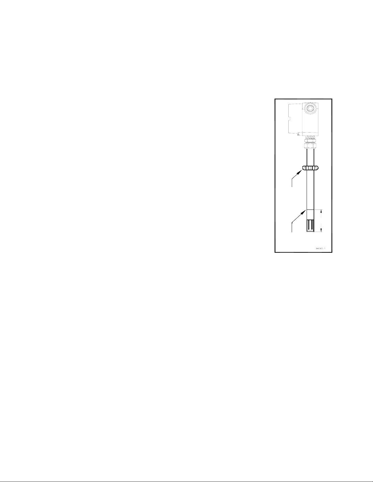
4. Verify stop clamp location (see Figure 4). A stop clamp is
attached to each probe as an indication of its insertion depth. It
is important that the stop clamp is securely in place to position
the sensors in the correct location and to ensure that the probes
do not contact the opposite pipe wall. Contact with the pipe wall
could damage the probe. The clamp’s location is determined
based on your submitted pipe diameter, as shown in SECTION
6.2, and is marked with a groove on each probe shaft. Refer to
this mark if a stop clamp is inadvertently moved. When
installed in the line, the two metal probe tips should be in the
middle of the pipe.
5. Prior to inserting probe, loosen the compression nut on the
thermocouple connector of the hot tap and clean the inner surface
STOP
CLAMP
of the thermocouple connector to ensure it is free of particles that
may cause probe damage.
6. Be sure to power up your RheoVac instrument system and
probe(s) for at least 30 minutes before inserting probes into the
vent line hot taps. DO NOT leave probe in vent line without
power or when flooding the condenser.
7. Install each probe. The probe should be mounted through the
pipe wall using the hot tap assembly. The probe installs so that
EXTRACTION
LINE
(ETCHED)
Figure 4 Probe
Stop Clamp
6''
the two sensor tips are side-by-side across the gas stream. Each
probe has a flow directional arrow on the junction box. Make sure the probe
orientation is correct. When installing under vacuum, do not allow the clamp to
“slam” against the seal nut upon opening the valve. Grasp the probe firmly, with
hand against the seal nut, before opening the ball valve. Allow the probe shaft to
slide slowly through the valve by controlling the amount of grip on the probe shaft.
Special installation instructions, if any, will be noted in SECTION 6.
8. When removing the probe from the vent line, loosen the compression on the
thermocouple connector of the hot tap and slowly pull the probe out of the line until
the extraction line is visible (see Figure 4). Close the ball valve and remove the
probe from the hot tap.
2.3 ELECTRICAL CONNECTIONS
IMPORTANT — Inspect and VERIFY these electrical connections carefully. Improper
connection could damage electronic components and sensor function. If additional holes need to
be drilled in the processor enclosure, remove the electronics subassembly (mounted on a mounting
plate) and temporarily store inside an ESD bag in a safe, clean place. Do not drill with electronics
boards inside the enclosure.
- 8 -
Page 11

A. Main Processor Unit (see Figure 5)
1. Sensor Power and Communication Line
: Connect the distribution box to this main
processor box using the RS-485 communications/power cable. Follow indicated
connector color code. [communications
: white (A), blue (B) and shield (SH); power:
24Vdc, red (+), and black ()]
2. Main Power
: Connect main power terminals to a dedicated 100-250Vac, single phase,
15-amp circuit. An external disconnect switch should be used for disconnecting power to
the system during outages. Power connection wires should be at least 18 gauge and
comply with accepted wiring codes. SW1 on the power input PWA (printed wiring
board #01011-5) is used for cycling power to reset.
3. Network Connection (Recommended): The Ethernet connection at CN3 on the CPU
interface PWA (printed wiring board #08017-1) is an RJ-45 style jack. A 10-foot
Ethernet Cat5 crossover cable is supplied with the unit for laptop connections. Intek
recommends using this connection for all data transmissions and RheoVac
communications because:
a. More measured data is accessible through the network connection.
b. Software and calibration file updates can be done remotely.
c. Archived data files can be easily retrieved and analyzed by Intek through online
software available at www.MyCondenser.com
4. Serial Communication
: Connector JP3 on the CPU interface PWA (printed wiring
.
board #08017-1) is the RS-232 serial communication interface. This interface should
only be used for distances of 20 feet or less, such as to a laptop computer. A 20-foot
serial cable with a DB-9 connector is available from Intek upon request (see Figure 6
and Table 1). An RS-422 serial communication interface is present for long data
communications when configured without 4-20 mA outputs. Note: Intek recommends
using the network connection for all data transmissions and RheoVac communications.
Table 1 RJ-11 to DB-9 Module Adapter
RS-232 CONFIGURATION RS-422 CONFIGURATION
RJ-11 Pin Out DB-9 Pin Out RJ-11 Pin Out DB-9 Pin Out
1 Tx (transmit) 1 N/C 1 Tx+ (transmit+) 1 RxS (receiveS)
2 N/C 2 Tx (transmit) 2 TxS (transmitS) 2 Rx+ (receive+)
3 Rx (receive) 3 Rx (receive) 3 Rx+ (receive+) 3 Tx+ (transmit+)
4 N/C 4 N/C 4 RxS (receiveS)4 N/C
5 Power (+5V) 5 Ground 5 Power (+5V) 5 Ground
6 Ground 6 Pulled high 6 Ground 6 TxS (transmitS)
7 N/C 7 7 TBD
8 Pulled high 8 8 TBD
9 N/C 9 9 TBD
- 9 -
Page 12
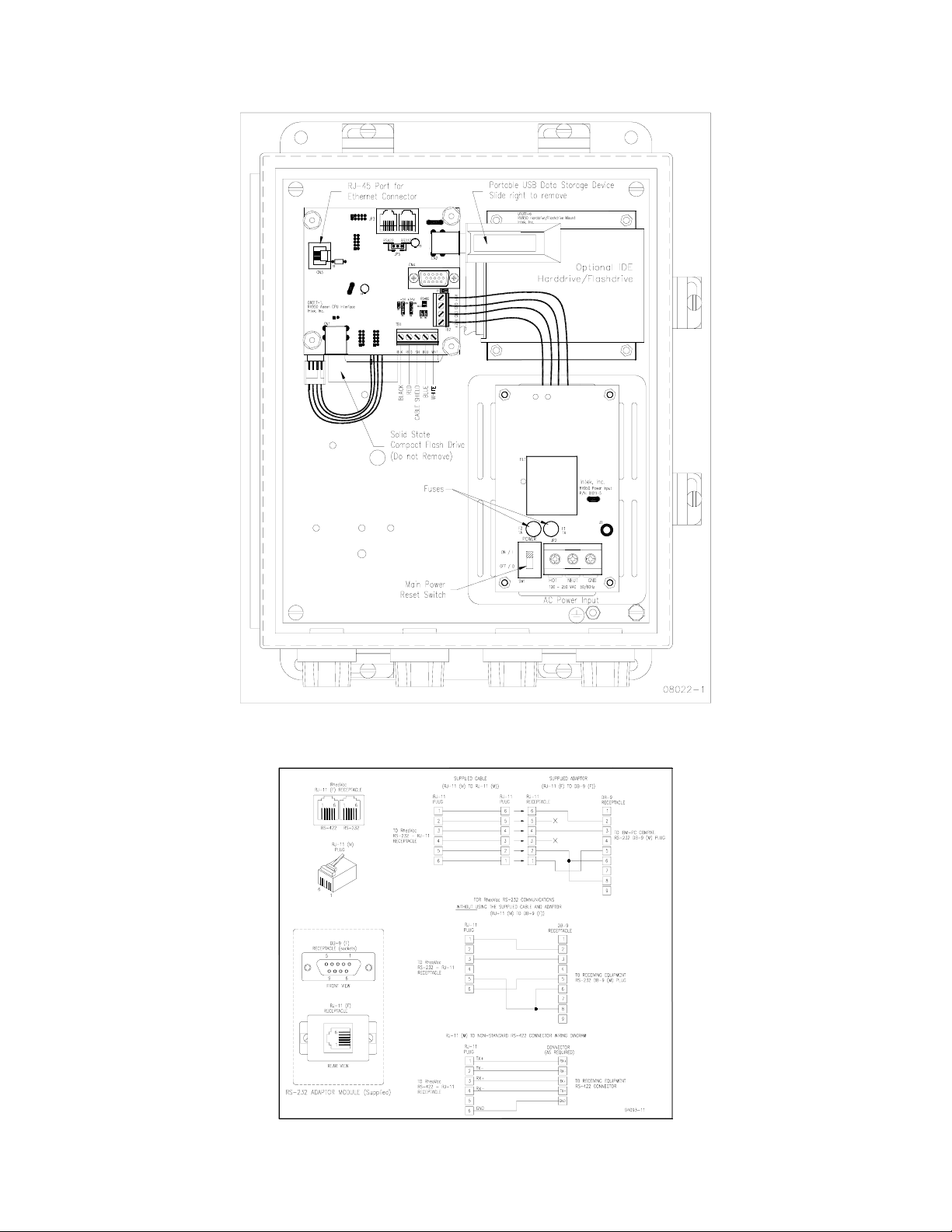
Figure 5 Output Connections and Set-up
Figure 6 Serial Communication Interface
- 10 -
Page 13

B. Distribution Box (see Figure 7)
1. Connect the RS-485 wires (blue, white and shield) and 24Vdc power (red and black)
from the main processor unit to screw terminal, JP1.
2. Install ½” liquid-tight conduit between the distribution enclosure and the probes unless
½” rigid conduit is used for long distance runs. Use a minimum of 6 feet of liquid-tight
conduit at the probes.
3. The probe connector comes with an adapter which allows the attachment of the ½”
flexible conduit connector.
4. Connect the probes to the distribution enclosure using the manufacturer supplied four
conductor shielded cable to any screw terminals labeled JP3 to JP6. Probe cable
connections are shown in Figure 7.
5. For multiple distribution box configurations, screw terminal JP2 will be used to wire
the manufacturer supplied four conductor shielded cable to screw terminal JP1 on the
next distribution box in series.
6. Optional — Connect the transmitter box to the distribution box using a RS-485 cable.
7. If no additional distribution boxes are used, ensure the outgoing termination resistor
(JP7 or JP8) is enabled.
Figure 7 Distribution Box
- 11 -
Page 14

C. Transmitter Box (optional, see Figure 8) — For driving eight (8) remote 4-20 mA analog
signals from one RS-485 input port. Note: Intek recommends using the network
connection for all data transmissions and RheoVac communications.
1. Connect the RS-485 communications/power cable from the distribution box (RS-485:
white and blue wires; 24Vdc power: red and black wires).
2. Connect up to eight (8) signal wire pairs to the indicated terminals for isolated 4-20mA
outputs.
Figure 8 Optional Transmitter Box
3. Figure 8 provides the RheoVac wiring detail for the 8 channel 4-20 mA outputs. Table
2 provides the appropriate connection identification. Model 950 transmitters are
configured as active (transmitter sources the current) when shipped. To change to the
passive mode (receiver to source the current), extract each small 4-20 board, find the
JP1 pins, and move the two jumpers from the “Act” pins to the “Pass” pins (two
positions to the right of factory settings). Figure 9 shows the current output circuit.
The figure also illustrates the active mode and the passive mode configurations.
Table 2 Optional 4-20 mA Configuration
Channel
1 Actual Volume Flow
2 Total Mass Flow
3 Water Vapor Flow
4Pressure
5 Water Vapor/Air Mass Ratio
6 Relative Saturation
7 Air In-Leak
8 Temperature
Output Parameter
- 12 -
Page 15

Active Configuration Passive Configuration
Vdd
from RheoVac Supply
R2
10 Ohm
Terminal
CAUTION: Do not move config.
jumpers if instrument is powered.
Terminal
05026-1
Q1
RFL2N05
or Equiv.
Q1
RFL2N05
R1
75 Ohm
Isolated Circuit Isolated Circuit
or Equiv.
R1
75 Ohm
Figure 9 4-20 mA Output Circuit
- 13 -
Page 16

D. Probe: CAUTION — Do not cross thread connection. The probe is supplied with a
convenient plug-in connector. The male side of the connector comes installed in the
probe junction box. The female side is usually shipped loose and must be installed onto
the supplied DeviceNet™ type 5711 cable once it is run from the Distribution Box to the
probe. The wiring detail for the female plug-in connector (Turck p/n B4151-0/9) can be
seen in Figure 10. These connectors will use either the “backshell nut” or “conduit
connector” depending on whether the cable is installed in a liquid-tight conduit. When
installing without conduit, use the backshell nut; when using liquid-tight conduit, use the
conduit connector with o-ring.
1. Slide all of the appropriate parts onto the cable as shown.
2. Strip the cable conductors as shown. The connector has 5 retention screws to hold the
wires in place. The use of crimp pins on the wires will greatly increase connection
reliability.
3. Loosen all 5 retention screws (do not completely remove).
4. Insert the wires, in accordance with color-coding shown (see Figure 10, insert).
5. Tighten the retention screws on each wire.
6. Reassemble the connector parts.
2
3
1"
3/8"
1
Figure 10 Probe Connector Assembly
- 14 -
Page 17

SECTION 3 — OPERATION
The RheoVac system is calibrated, compensated, and linearized for a wide range of flowing
media temperatures, pressures, and water vapor contents. However, abrupt changes in these
parameters can cause the instrument to temporarily read the flow rate improperly, which could
lead to transient spikes in the flow indication. In particular, if liquid (water) hits the probe tips,
there will be high flow indications until all the water vaporizes. If liquid (water) is present for
extended periods, the performance of the instrument will be compromised or the sensors can be
damaged.
3.1 SYSTEM START-UP
Verify wiring from SECTION 2.3 is correct. With all power off, place the power OFF/ON
switch, SW1 on printed wiring board #01011-5, to “ON.” Close the main processor enclosure
lid. While watching the main processor display, apply power to the instrument. After about
twenty seconds the display should initialize to “Health Check in Progress” followed by
additional initialization status messages. Within two minutes the display should indicate “Air InLeak.”
Be sure to power up your RheoVac instrument system and probe(s) for at least 30 minutes before
inserting probes into the vent line hot taps. DO NOT leave probe in vent line without power or
when flooding the condenser. (See SECTION 1.5 for precautions and recommendations.)
3.2 PORTABLE USB DATA STORAGE/Warranty Registration Instructions
Intek’s warranty program is stated at the front of the manual. To validate warranty:
1. Locate portable USB Data Storage Device in the main electronics enclosure (see Figure
5).
2. Grasp bracket and carefully remove portable USB Data Storage Device.
3. E-mail all RheoVac instrument data to techsupport@intekflow.com or upload to
www.MyCondenser.com
4. Replace portable USB Data Storage Device in the main electronics enclosure.
CAUTION - Do not attempt to use non-Intek approved USB flash drives with the RheoVac
instrument. Your RheoVac instrument may not have the proper drivers installed for other USB
flash drives. This may cause the RheoVac instrument to lock-up and require service.
.
3.3 DISPLAY
The RheoVac 950 has a 2x20 alphanumeric scroll-through display that shows seven parameters
for each probe. The display shows Air In-leakage, W/A Mass Ratio, Total Mass Flow,
Temperature, Pressure, Relative Saturation, or Actual Volume Flow (as well as Time/Date,
Software Version, or Serial Number). To change the displayed parameter, press the Scroll Up or
Down arrows. The display units can be changed from English or Metric units by pressing the
Units button.
If the Model 950 has two or three probes the display will show two or three serial numbers at a
time, one for each probe. The numbers will be in order, from the lowest serial number to the
highest, reading from left to right on the display. Example: 02611-1, 02611-2 and 02611-3.
- 15 -
Page 18

3.4 COMMUNICATIONS
Typical RheoVac 950 instruments have an Ethernet port, two serial communications choices
(RS-232 or RS-422) and optional eight 4-20 mA output signals for each probe. All 4-20 mA
output signals are linearly scaled such that 4 mA represents 0% of the rated full scale value
(except temperature, which is 0(C) and 20 mA represents 100% of the rated full scale value
(temperature is 100(C). The standard full scale values and definitions of all process variables
are listed in Table 3. Note: Intek recommends using the network connection for all data
transmissions and RheoVac communications. Communication with the RheoVac unit using Intek
supplied software is discussed in Appendix A of this manual.
Table 3 Process Variable Definitions and 4-20 mA Range*
4-20 mA
PROCESS VARIABLE
FULL
SCALE
ACTUAL VOLUME FLOW
ACFM [m
3
/hr]
TOTAL MASS FLOW
lbs/hr [kg/hr]
WATER VAPOR MASS FLOW
lbs/hr [kg/hr]
RheoVac PRESSURE
” Hg [mm Hg]
5000
[8,500]
10000
[4,536]
8000
[3,629]
30
[762]
WATER to AIR MASS RATIO 20
RELATIVE SATURATION
[%]
AIR IN-LEAK
SCFM [nm
3
/hr]
RheoVac TEMPERATURE
°F [°C]
*See Custom Information section (Section 6) for custom units of measure.
100
100
[169.9]
212
[100]
PROCESS VARIABLE DEFINITION
The actual volumetric flow rate of gases leaving the
condenser. It is a measure of exhauster capacity.
Decreased capacity means pump degradation.
The total mass flow rate of the flowing gas. Note:
this value is not a measure of air in-leak. It is a
measure of total vapor and air removal and
exhauster operating capacity.
The water vapor component of the flowing gas
being removed from the condenser.
Absolute pressure at the RheoVac probe head.
Should be equal to or less than turbine back
pressure.
Ratio of water vapor flow rate to dry air flow rate.
Defines “vacuum quality.”
The percent concentration of water vapor in the
extraction line relative to saturation.
Actual measure of air volume flow rate passing the
RheoVac sensor head, normalized to standard
conditions (70°F, 29.9” HgA).
4 mA = 0°C or 32°F, 20 mA = 100°C or 212°F
Temperature of the flow media at the RheoVac
probe head.
3.5 DATA PROCESSING
A very important part of understanding your condenser system comes from evaluating the data
that is measured, created and stored by the RheoVac instrument. A data file is created for each
calendar day that the monitor is operating. The ability to review stored data has been invaluable
when troubleshooting condenser problems. The column heading for each archived data file is
seen in Table 4. Intek provides solutions for viewing and analyzing data.
Table 4 Column Headings for Data Downloads and Archived Data*
Time
Stamp
Actual
Vol.
Flow
(ACFM)
*See Custom Information section (Section 6) for custom units of measure.
Total
Mass
Flow
(lbs/hr)
Water
Vapor
Mass
Flow
(lbs/hr)
RheoVac
Pressure
(“HgA)
Water
Vapor
Sp. Vol.
3
(ft
/lb)
Water
to Air
Mass
Ratio
(lb/lb)
Relative
Satura-
tion
(%)
- 16 -
H2O
Partial
Pressure
("HgA)
Air
Flow
In-Leak
(SCFM)
Probe
Temp.
(ºF)
RS
Temp.
(ºF)
Raw
Total
Mass
Flow
(lbs/hr)
¨T
(ºF)
RS
Out.
Page 19

A. Using www.MyCondenser.com for plotting (Plotting tools are available free on our
website for analyzing RheoVac Model 950 data). Must first register as user.
1. Open the website, www.MyCondenser.com
2. If you are not registered, click the ‘register’ link at the bottom of the page and follow
the on-screen instructions.
3. Log in to the website using the username and password created during the
registration process.
4. Click on the ‘RheoVac’ pull down menu at the top of the page and select
‘RheoPlotter’ from the pull down menu.
5. Click on the ‘Help’ link to learn how to upload files, create plots, and change axis
limits.
6. Plots, data, and questions can be submitted to Intek for evaluation through the
‘Submit Data and Question to Intek’ link at the bottom of the page.
7. Submitted questions and responses are posted on the user’s individual private forum.
Figure 11 is an example plot.
.
Figure 11 RheoVac data plotted – an illustration
B. Other features available on www.MyCondenser.com
1. Web Tutorials
Tutorials can be found in the help menu. This section includes presentations on
condenser theory, instrumentation, case studies, and condenser services provided by
Intek.
2. Case Studies
Posted presentations show events and conditions captured by the RheoVac condenser
monitor and how the instrument helped to troubleshoot or solve upset conditions.
Case studies include information on pump issues, air in-leakage events, steam jet air
ejector problems, and general condenser performance troubleshooting, etc. Case
studies captured by the Rheotherm Circulating Water Flow and Fouling Meter are
also presented and discussed. Illustrations on macrofouling, thermal stratification,
circulating water pump degradation, and identification of condenser design
deficiencies are highlighted.
- 17 -
Page 20

3. Public Forum
Registration is not required for viewing access to the public forum. This forum is a
way to freely exchange ideas and post questions (with registration) to professionals
within the power industry.
4. Private Forum
Through the private forum, the registrant will be able to communicate directly with
Intek engineers regarding data analysis, condenser services, instrumentation, and
other questions. Posts on this forum will only be visible by the user and Intek
engineers.
5. Continuous Condenser Monitoring and Performance Analysis
Intek offers services where Intek will continually monitor the user’s condenser(s) and
provide feedback, action items, and selected performance reports. More information
regarding Intek’s condenser services is available upon request.
3.6 CUSTOM SOFTWARE
Custom software may be developed by the user to receive and archive RheoVac data into a
computer system. The electronics has a serial data protocol of 9600 baud, no parity check, eight
data bits and one stop bit (i.e., 9600,N,8,1). Each transmitted group of data is sent in a standard
ASCII coded format representing each process variable value, instrument identification and
status information.
The data stream consists of 13 fields, followed by a carriage return <RETURN>. The first ten
fields, nine bytes each, are the process variables. Following the process variables are the
RheoVac serial number, nine bytes; the process identification tag number, 15 bytes; and the
RheoVac system status, seven bytes. The data stream is then ended by a single <RETURN> byte
(ASCII code 13). The total number of bytes transmitted in each data stream is 122 bytes per
probe including the trailing <RETURN>. This data group is sent approximately once every three
seconds. Table V shows the field names and number of bytes in one data stream.
Table 5 Serial Output Data Stream*
Actual
Volume
Flow
(ACFM)
bytes 9bytes 9bytes 9bytes 9bytes 9bytes 9bytes 9bytes 9bytes 9bytes 9bytes 15bytes 7bytes 1byte
* See Custom Information section (Section 6) for custom units of measure.
Total
Mass
Flow
(lbs/hr)
Water
Vapor
Flow
(lbs/hr)
RheoVac
Pressure
("Hg abs)
Water
Vapor
Sp. Vol.
3
/lb)
(ft
Water to
Air Mass
Ratio
(lb/lb)
Relative
Satura-
tion (%)
O
H
2
Partial
Pressure
("Hg abs)
Air
Flow
In-Leak
(SCFM)
Probe
Temp.
(°F)
Instr.
Serial
Number
ID Tag
No.
Status
Term.
<CR>
9
Each of the first ten process values are sent in the fixed decimal format of XXXX.XXXX with
leading and trailing zeros inserted to maintain the nine character length. The next three fields are
ASCII text strings followed by the <RETURN>. Example: The nine bytes for an air in-leak of
10.0 SCFM would be: 0010.0000, or 48,48,49,48,46,48,48,48,48 ASCII.
- 18 -
Page 21

SECTION 4 — MAINTENANCE
4.1 CALIBRATION
The RheoVac instrument is calibrated at the factory in a calibration system which replicates the
condenser and vacuum line environment. The system is designed to simulate the temperature,
pressure, water vapor relative saturation, and flow rate under the gaseous fluid conditions found
within the power plant vacuum line.
In general, calibrations should be valid over a two-year period if the probe is well maintained.
Should the unit require re-ranging or recalibration, note the serial number of the RheoVac
instrument and contact the factory concerning recalibration cost and turn around times. Refer to
SECTION 5 — CUSTOMER SERVICE of this manual for additional information.
Contact Intek for calibration, condenser monitoring service plans, instrument service agreements
as well as other Intek products and services for the condenser and the power industry.
4.2 SPARE PARTS
It is advantageous to have a spare probe. Should a spare probe be desired, it can be ordered and
stored for installation at any time. A spare probe will come with a parameter disk with
calibration files that will need to be uploaded to the main electronics along with instructions to
complete the update and install/replace the probe (see SECTION 4.4).
Spare fuses should be available for replacement of blown fuses. Appropriate fuses to stock are:
x 500 mA fuse, slow blow, Wickmann part number 3720500041 or equivalent, for probes.
x1 A fuse, slow blow, Wickmann part number 3721100041 or equivalent, for the main
electronics.
There are no other normally recommended spare components to stock.
To replace the fuse in the main electronics: locate the AC Power Input board (#01011-5 shown in
Figure 5) in the lower right hand corner of the main electronics box. Slide the power switch to
the “OFF” position to disable power to the electronics. The fuses are shown at locations F1 and
F2 (spare). Gently pull the fuse(s) from their sockets and gently insert the replacement 1 Amp
fuse(s) as appropriate. Slide the power switch back to the “ON” position to enable power to the
electronics. Close hinged lid and verify display backlight is on. Clamp close the enclosure lid,
and tighten the latch screws.
- 19 -
Page 22

4.3 TROUBLESHOOTING
4.3.1 Diagnostic Messages
Table 6 provides a guide for plant personnel to identify causes of problems and determine
appropriate actions to resolve problems observed. If problems are encountered and factory
assistance is desired, please contact the factory.
Table 6 Troubleshooting Guide (Diagnostic Messages)
MESSAGE CODE
Description/Symptom
MSG-0
Communications not
being received from
probe(s)
MSG-1
Invalid data received
from probe(s)
MSG-2
Flow sensor heater
“OFF”
MSG-3
RS sensor power
“OFF”
MSG-4
RS heater “OFF”
MSG-5
Circuit issue
MSG-6
Temperature alarm
(above 210ºF/99ºC)
MSG-7
Wet probe
MSG-8
RS sensor problem
Mass flow output
saturates high, will not
respond to flow changes
Mass flow output
saturates low, will not
respond to flow changes
PROBABLE CAUSE ACTION
1. Improper cable hookup
2. Blown main fuse
3. Failed RS-485 circuit
4. Damaged flow sensor
1. Failed RS-485 communications
component
1. Blown heater fuse
2. Failed electronic component
1. Probe temperature too high
2. Liquid water on probe tips
1. Component failure 1. Contact factory
1. Problem with circuitry 1. Contact factory
1. Steam in exhaust pipe
1. Liquid water on probe tip
1. RS sensor problem
1. Flow rate is not within range of
calibration
2. Blown heater fuse
3. Failed electronic component
1. Flow rate is not within range of
calibration
2. Failed electronic component
1. Verify plug-in connector is properly
mated
2. Check F1 fuse on probe board
3. Check all cable connections
4. Contact factory
1. Check wiring
2. Contact factory
1. Contact factory
1. Check that probe temperature is
<160ºF
2. Contact factory
1. Remove probe or cool line ASAP!
2. Once line has cooled down and
probe is reinstalled, check unit for
proper function
1. Remove probe ASAP!
2. Contact factory
1. Remove from line, allow 24 hrs with
power on to dry out RS sensor,
reinsert probe
2. Contact factory
1. Contact factory about re-ranging
instrument
2. Contact factory
1. Contact factory about re-ranging
instrument
2. Contact factory
- 20 -
Page 23

4.3.2 Software Communication Problems
When using the RheoVac software on a PC, the software may give you a “Communication Error
or Message.” Use the information in Table 7 and Table 8 to determine the source of this
message and appropriate action.
Table 7 Troubleshooting Guide (serial connection software communication errors)
OBSERVATION PROBABLE CAUSE ACTION
Appears the first time
the application was
executed
Appears intermittently
after application has
been running
normally
Completely stops
working after
application was been
running normally
Cannot be made to
work at all with Com3
or Com4
Note: Windows is a registered trademark of Microsoft Corporation in the United States and other countries.
1. Instrument not connected to the
software defaulted serial port
2. Communication connections not made
or instrument is not powered
1. Electrical noise interfering with
communications
2. Too many applications running in
windows
3. Another application is conflicting
with this comm port or IRQ
1. Instrument has stopped
communicating
2. Loose or damaged communication
connection
1. Works fine on Com1 or Com2 but
does not work on other port due to
other hardware conflicts such as a
modem
1. Change serial comm port setting and
hit “Retry”
2. Check connections and instrument
power
1. Change to RS-422 communications,
reroute or shield cable
2. Close other applications until problem
self corrects
3. Change to a different comm port
1. Check instrument power or look at
instrument display for fault status
2. Check cable adapter at back of PC or at
any other splices or at instrument
1. Using Windows Control Panel —
System utility, check for IRQ or I/O
hardware conflict — ADVANCED
USERS ONLY
Table 8 Troubleshooting Guide (ethernet connection software communication errors)
OBSERVATION PROBABLE CAUSE ACTION
Connection error when
attempting to connect
to the instrument using
the supplied User
Interface Software
(UIS)
Error occurs when
attempting to use the
UIS trending option or
file update option
1. Incompatible network
settings on the User
Interface Computer (UIC)
2. IP address not identified
3. Bad or incompatible Cat5
cable
1. Lost connection
2. Incompatible UIS version
1. Verify settings on the UIC outlined in Appendix B
2. Reboot the UIC and RheoVac Model 950 while
connected
3. Verify correct Cat5 cable (for peer to peer
connection use crossover cable, for networked
connection use straight cable)
4. Contact factory
1. Restart UIS
2. Contact factory
- 21 -
Page 24

4.3.3 Primary Signal Validation
If the RheoVac instrument is operating without message indications but output readings are
questionable, check your RheoVac instruments primary readings per Table 9. Please send to
Intek by e-mail the following plant data: turbine back pressure, hotwell temperature, load, and
inlet and outlet circulating water temperatures, along with at least 24 hours of data from the
RheoVac instrument/probe for the same time period. A support engineer can examine the data
and respond to the inquiry.
Table 9 Verify Primary RheoVac Readings
Pressure, PRV :
Temperature, TRV:
Total Mass Flow, m
Relative Saturation, RS RS < 100% and varying; typically 80 to 97%
T
Probe pressure should be 0.1” to 0.5”HgA lower than condenser pressure
< P
P
RV
Probe temperature may be as high as hotwell temperature or as low as circ
water inlet temperature; typically a few degrees below circ water outlet
temperature and hotwell temperature
T
cw,in
T
cw,out
mT1,000 lb/hr (for large exhauster)
225 lbs/hr (m)
if m
(0.1 to 0.5”HgA typical, 1” HgA under high AIL)
Cond
TRV T
± 4(F TRV T
> 1,000 lb/hr, check RheoVac internal T; > 20(F
T
HW
HW
600 lbs/hr (per exhauster, typical)
T
4.4 HARDWARE/SOFTWARE MODIFICATIONS AND UPDATES
4.4.1 Updating Software
Normally, updating the main software residing on the RheoVac Model 950 is done at the factory.
However, software improvements or other factors may necessitate a user installation or update of
a new main program. When this is required, instructions will be supplied, along with the
software.
4.4.2 Replacing Probes
If it is necessary to replace one of the probes, a new probe and diskette or CD (with probespecific calibration data) can be ordered from Intek.
4.4.3 Adding Additional Probes
Each RheoVac Model 950 system can communicate with up to three probes simultaneously.
Additional probes can be easily added to systems that have fewer than three probes. Each
additional probe will be shipped with a set of calibration files that must be installed on the main
RheoVac instrument electronics. Refer to drawings for mechanical and electrical connections.
Specific instructions will be supplied with the probe(s).
- 22 -
Page 25

SECTION 5 — CUSTOMER SERVICE FROM THE
CONDENSER EXPERTS
Intek’s corporate philosophy is to help solve our customers’ difficult flow measurement
problems. When you purchase a RheoVac system you also receive Intek’s dedicated customer
service. For sales or product service, call your local representative or Intek directly at (614) 8950301 8AM to 5PM EST/EDT weekdays or fax us anytime at (614) 895-0319. E-mail inquiries
should be sent to sales@intekflow.com or techsupport@intekflow.com. Our customer service
staff will provide assistance promptly.
5.1 QUESTIONS ON EXISTING HARDWARE
To allow us to help you more quickly, please have the serial number of the equipment available
before you call.
5.2 TROUBLESHOOTING
If you have reviewed SECTION 4.3 TROUBLESHOOTING and have questions, please call our
experienced engineers for assistance. In many cases we can solve a problem over the phone.
Please provide as complete a description as possible of the problems encountered.
5.3 FACTORY AND FIELD SERVICE
If you request field service to help with condenser performance problems, Intek has, for a fee,
experienced engineers who can be assigned to meet your needs. For RheoVac instrument related
questions, if a problem cannot be solved over the phone, with your help, we will determine if
factory service or field service will be the best solution. When returning instruments/probes for
factory service be sure to carefully pack the instrument/electronics; extra care should be taken to
protect the probes from damage in shipment. Use the factory supplied PVC probe protection
tube and custom shipping box for probes when possible.
To request factory service on your instrument, a Return Material Authorization (RMA) and
purchase order is required. Our customer service staff will assist you with the required
information to return equipment for service.
5.4 NEW EQUIPMENT AND SERVICES
For information on Intek’s power plant instruments and services, such as new RheoVac system,
condenser flow and fouling meters, liquid or gas flow meter or flow switches, circulating water
flow and fouling meters or condenser inspection, analysis, or monitoring services, contact the
Intek technical sales department by phone/fax/email. Our staff will be pleased to answer all
questions and provide our recommended solutions, instruments, or services.
Intek has developed unique solutions for plants experiencing problems with dissolved oxygen,
heat rate and excessive backpressure. We provide comprehensive condenser diagnostic and
report services. Plant and RheoVac data is automatically transmitted to Intek and results are
published via online reporting and regular hard copy reports. Please call us to discuss your
observations, concerns, and needs.
- 23 -
Page 26

Intek has many years of experience helping customers solve their complex condenser problems.
Intek's monitoring services ensures plants have expert assistance with collecting, interpreting,
and reporting on condenser operations. In many cases, excess back pressure problems can be
predicted before have an affect on power production. If you would like a quotation on a
complete condenser monitoring and reporting solution, please call.
5.5 CONDENSER MANAGEMENT AND RheoVac TRAINING
Intek conducts Condenser Operations and Management workshops to educate professionals on
RheoVac and Rheotherm instrumentation as well as condenser operations and theory. During
these workshops, degraded condenser performance is discussed including root cause analysis for
poor performance and condensate chemistry issues. Solutions are presented and discussed.
Several training tools and reference material can be found on our website,
www.MyCondenser.com. Tutorials can be found in the help menu, included are presentations on
condenser theory, instrumentation, case studies, and condenser services provided by Intek.
Posted case studies show events and conditions captured by the RheoVac condenser monitor and
how the instrument helped troubleshoot or solve upset conditions. Case studies include
information on pump issues, air in-leakage events, steam jet air ejector problems, and general
condenser performance troubleshooting. Case studies captured by the Rheotherm Circulating
Water Flow and Fouling Meter are also presented and discussed in the website. Macrofouling,
thermal stratification, circulating water pump degradation, and identification of condenser design
deficiencies are highlighted.
- 24 -
Page 27

SECTION 6 — CUSTOM INFORMATION
6.1 UNIT IDENTIFICATION
Model no.:
Serial no.:
Customer identification:
6.2 CONFIGURATION
The marked (X) items denote the configuration of this unit as originally shipped from the
factory.
Pipe Connection: Hot tap with 1½" MNPT connection
Input Power: 100-250 Vac, 50/60 Hz
Outputs:
Analog: 8 outputs (4-20mA) for each probe
Digital: Ethernet
RS-232/RS-422
Data Access: Ethernet communication
Portable Data Storage: Portable USB Data Storage Device
Enclosures shipped: Cables Shipped:
Processor Box 5711 interconnect cable (RS485) -
Distribution Box Cat5 Ethernet cable - 10 ft
Transmitter Box RS232 communication - 20 ft
Software: Windows compatible RheoVac 950 system software, — Version 051509
User interface software on CD — Version 112008
Calibrated for customer line size of inches, schedule
6.3 SPECIAL INSTRUCTIONS
The next page shows a sketch of a typical layout for a Model 950 with all components located
near each other on the plant floor. Other configurations can be used, but there are rules as to
how an RS485 signal can be run, so if you are thinking of using some significantly different
arrangement for your installation, please contact the factory (614-895-0301) to review your
plans.
- 25 -
Page 28

APPENDIX A - RheoVac® Instrument User Interface Software
A.1 INTRODUCTION
User Interface Software (UIS) is provided on CD-ROM with every RheoVac instrument. This
software is used to communicate with the RheoVac unit from a User Interface Computer (UIC).
Some of the functions of the software can be performed using a serial cable, while all functions are
available using an Ethernet connection. An Ethernet crossover cable is provided with each RheoVac
instrument for the purpose of connecting a UIC directly to the RheoVac unit. The network functions
are also capable of being used from any network computer if the RheoVac instrument is connected
directly to the same network. In this case, the supplied crossover cable is not used; rather a straight,
high noise-immune Ethernet cable with RJ-45 plug is used (supplied by customer).
Most details regarding use of the software can be found in the active help files from the pull down
Help menu when using the software.
A.2 SOFTWARE INSTALLATION
A User Interface Computer (UIC) is required to access stored data and real time data of all
parameters. A laptop is suggested for easy access to the main processor unit. Intek does not supply
UICs but recommends the following System Requirements (minimum recommended):
Minimum System Requirements:
Windows 98, Windows NT, Windows 2000 or Windows XP Operating Systems
Pentium III, 400 MHZ processor with 128 MB RAM
SVGA 800 x 600 display
One CD-ROM drive
One 10/100 Ethernet Port
Recommended (Optional):
One 3.5 inch floppy disk drive (probe recalibration data files can be provided on diskette)
One RS-232 serial port with DB-9 connector
The User Interface Software should be installed onto the User Interface Computer. Install the
software by inserting the CD-ROM supplied with the manual into the CD-ROM drive and follow
the on screen prompts. A folder, C:\RHEOVAC will be created and files will be copied to this
folder. The executable file is RheoVac User Interface.exe and the others are drivers and
configuration files that must remain in the RHEOVAC folder. If a previous version of User
nd
Interface Software is on the UIC, you will need to launch the installer a 2
time.
A.3 USER INTERFACE SOFTWARE (UIS) SELECTION
After installation, the user interface is initiated by selecting [START\PROGRAMS\RHEOVAC\
RHEOVAC USER INTERFACE]. The main menu appears, prompting for a selection of RS-232
Serial Communication or Ethernet Communication Utility. A list of functions for each utility
appears below the green selection buttons.
I:\OFFICE\WPMANUAL\RV950 APPENDIX A3.wpd January 29, 2007
- A1 -
Page 29

Make sure the proper cable connection has been made and select the desired communication type
by clicking on either green button.
Figure A - Initial UIS computer Screen
A.4 RS-232/422 COMMUNICATION
This function requires a serial cable and connector, available on request, to connect the UIC and the
RheoVac instrument electronics. This connection allows the user to view real time data of important
parameters in a convenient gauge screen layout. From this gauge screen, the user may choose to
graph a single parameter for all probes, graph all parameters for a single probe, or archive data
directly to the UIC. The archive rate can also be adjusted. These are the only functions available
using serial communication. No commands or updates can be sent to the RheoVac instrument using
this communication method.
A.5 ETHERNET COMMUNICATION
User interface using Ethernet connection allows the user to: synchronize the RheoVac clock with
the UIC clock, retrieve stored data
1
, update files1, change line size, and access data. These network
access utilities are performed from a user interface computer (UIC) connected directly (peer-to-peer)
to the RheoVac unit using a crossover network cable or from a network computer when the RheoVac
instrument is connected to a network (LAN/WAN)2 using a straight Ethernet cable.
Each RheoVac instrument is identified by a unique network ID. The ID begins with the letter “R”
followed by the first five digits of the serial number found on the unit. (RheoVac Model 950 devices
which have not been serviced by the factory since 2005 may use the serial numbers or “RheoVac
1
File transfer can also be accomplished using Windows Explorer or Network Neighborhood
2
Specific network set-up at Intek may be required.
I:\OFFICE\WPMANUAL\RV950 APPENDIX A3.wpd January 29, 2007
- A2 -
Page 30

950" network ID). The user must select the network ID from the pull down menu following the
selection of Ethernet Communication utility from the Main Menu. If the Network ID is not in the
list, select Add New ID and enter the correct six character Network ID. When a new ID is added
to the list, it will be saved as the default for later use. Selecting the correct ID will initiate
communication with the RheoVac instrument. Software features, in addition to those detailed above,
are described within the User Interface Software itself.
A.6 SOFTWARE OPERATION
1. Set Clock
(available with Ethernet connection only): Initiating this action will reset the
RheoVac time clock to agree with the time on your UIC. Make sure the UIC has the
correct time before proceeding.
2. Change Line Size (available with Ethernet connection only): Use this option to update
the instrument’s stored line size variable for proper volume and mass flow calculations.
You should only need this option if the probe is installed in a pipe size that is different
from the value set in the instrument at the factory. In Ethernet Communication, click on
the Line Size tab. On the pull down menu for pipe size, click on the new value, then click
on Save. Click Load to verify that the change was saved by the instrument.
3. Update Files
recalibration, or some other change in the RheoVac operating software is needed, this tab
will be used. Do not use it until then. Instructions will be supplied at that time.
4. Retrieve Data
accessed via Ethernet connection from the
The
RheoVac software creates a new data file each day. The file name is in the
(available with Ethernet connection only): If the probes are ever returned for
(available with Ethernet connection only): Stored data can be easily
RheoVac instrument to the UIC.
following format:
MMDDYY - P.dat
where MM = two digit month
DD = two digit day
YY = two digit year
P = probe designator (1, 2, or 3)
.dat = file extension
These data files are stored in tab delimited text format. See SECTION 3.5 to process data.
To copy a file for analysis, you must access the files on the RheoVac instrument. Open
Windows Explorer on the UIC. Type \\Network ID\RHEOVAC\DATA (Network ID is
generally “R” plus the first 5 digits of the serial number; see section A.5) on the address
line and press enter. Be careful not to alter any support files in this data folder. Use
the copy/paste functions (copy - Ctrl C; paste - Ctrl V) to put data files (.dat) on the
UIC.
5. Monitor Data
(available with Ethernet or RS-232 connection): Once RS-232 or Ethernet
is selected, the first screen, Figure B, shows the most recent value for each parameter.
I:\OFFICE\WPMANUAL\RV950 APPENDIX A3.wpd January 29, 2007
- A3 -
Page 31

Click on the small graph image to view a historical graph of that parameter. S e l e ct
from all available probes by clicking on the Probe S/N menu.
Figure B - User Interface Software Data Monitor Feature
To do real-time graphing, select from the graph menu. The screen shown in Figure C
appears.
Figure C - User Interface Software Graph Feature
I:\OFFICE\WPMANUAL\RV950 APPENDIX A3.wpd January 29, 2007
- A4 -
Page 32

This screen can be divided into four parts:
1. The Chart (or charts)
2. The X-Axis Controls
3. The Legend
4. The User Menu
These four parts work together in the following ways: As soon as the software is opened and valid
communication is established, the data collected for each probe is plotted on the chart(s). The
newest data points are displayed on the right of the chart and push older data points to the left, much
like many old-style strip chart recorders.
The horizontal scroll bar immediately below the chart(s) can be used to select which data points (i.e.,
data from a specific timestamp) from the chart are displayed on the legend below. Data points can
be selected either by clicking-and-dragging the scroll bar pointer or by simply single-clicking a spot
on the scroll bar.
The four buttons below and to the left of the scroll bar labeled 30 min, 1 hour, 2 hour, and 4 hour
can be used to quickly set the x-axis range of the chart(s) and the scroll bar. When using these
buttons keep in mind that the maximum x-axis value is always used as a reference and only the
minimum displayed x-axis value will be changed. You can also change both the minimum and
maximum x-axis value by double-clicking them with your mouse and entering a new value with
your keyboard. Changing the range of the chart (X or Y axis) changes only the data that is displayed
and does not delete or alter the data in any way.
The blue block (time/date) to the right of the 4 hour button displays the timestamp for the data point
currently being pointed to by the horizontal scroll bar. If the scroll bar is in the right-most position,
this value will automatically update when new data is received from the connected instrument.
The legend at the bottom of the screen displays the value of the data being pointed to by the scroll
bar and also is used to control where each data parameter is plotted. To access this feature singleclick on any parameter in the legend. Two things will happen. First, the background color of the
selected parameter will change in the legend, and second, the parameter will disappear from the
chart if you are in single-chart mode or jump from one chart to the other if you are in dual-chart
mode.
Single-chart and dual-chart modes are the first two selections available in the chart user menu. Also
available in the chart menu are selections to choose between manual and auto scaling for the y-axis
and to reset the maximum x-axis value to the most recently collected data point.
The legend menu is used to select which parameter or which probe is displayed. If a parameter is
chosen from this menu, that parameter will be displayed for all probes connected to the instrument.
If a probe is selected, then all parameters for that probe will be displayed.
The archive menu is used to set the rate that data will be archived to the hard disk of the computer
on which the user has installed the User Interface Software. These selections have no effect on the
data that is stored every minute on the hard disk of the RheoVac instrument itself. Data archived
I:\OFFICE\WPMANUAL\RV950 APPENDIX A3.wpd January 29, 2007
- A5 -
Page 33

to the user’s hard disk is stored in the “C:\RHEOVAC\DATA\” directory. The data is subdivided
into folders for each probe. A new file for each probe will be created each day that data is archived.
A.7 WARRANTY REGISTRATION/TECHNICAL SUPPORT
Sending Data to Intek: IMPORTANT
If the instrument is equipped with a portable USB data storage device as shown in Figure 5 (in the
main manual), remove this storage device after one week of operation and send to "Intek, Inc., 751
Intek Way, Westerville, OH 43082" to activate/secure warranty registration. This storage device
is programmed to capture the initial baseline data recorded by the RheoVac instrument.
The following paragraph is applicable to RheoVac 950 instrument users only:
The availability of plant data for periods corresponding to the RheoVac data are important to proper
diagnostic evaluation. Plant data of interest to the factory for the same time period are: turbine back
pressure, hotwell temperature, load, and inlet and outlet circulation water temperatures. The plant
data is necessary for correlating RheoVac measured data. The availability of this information at the
factory is very important to Intek’s ability to assist you in troubleshooting your instrument and/or
to respond to inquiries. This provides a baseline for the system and will help us support you should
future system problems arise. Our experienced support engineers can access the “before” and “after”
effects of an upset and work with you to identify and understand the problem, and develop solutions.
Additionally, most air removal piping conditions that are detrimental to probe operation can be
diagnosed before probe damage occurs. For this reason, we require a data download one week after
RheoVac system is placed into service. The download activates the one year warranty service.
the
Alternately, you may send to the factory an initial week or so of data (zipped format is preferred). The
simplest way is to copy all data files and the ‘event.log’ file to your UIC and send it via email to
techsupport@intekflow.com.
Note: Windows is a registered trademark of Microsoft Corporation in the United States and other countries.
I:\OFFICE\WPMANUAL\RV950 APPENDIX A3.wpd January 29, 2007
- A6 -
Page 34

APPENDIX B - RheoVac Model 950 Networking
B.1 INTRODUCTION
Use these instructions when making a peer-to-peer Ethernet connection between the RheoVac 950 and
the User Interface Computer (UIC), or an Ethernet connection between the RheoVac 950 and a Local
Area Network (LAN). Locate the section that covers your operating software.
B.2 WINDOWS 98 OR WINDOWS ME OPERATING SYSTEM
1. Ethernet Cable
:
a. UIC Connection: use CAT5 network crossover cable (supplied by Intek) to connect the
Ethernet port of the UIC to the Ethernet port on the RheoVac 950.
b. LAN Connection: use CAT5 straight high noise-immune Ethernet cable (not supplied)
with RJ45 plug to connect the Ethernet port of the LAN to the Ethernet port of the
RheoVac 950.
2. Workgroup Identification
: Unless otherwise requested, the Workgroup identification for the
RheoVac 950 will be WORKGROUP, which is the Windows 98 default setting. To check/set
the workgroup name: Right click on the Network Neighborhood icon on the UIC desktop.
Select Properties from the menu that appears. Select the Identification tab of the Network
dialog box that appears. Verify that Workgroup is WORKGROUP.
3. Check for Installed Network Components
: Right click on the Network Neighborhood icon
on the UIC or LAN computer desktop. Select Properties from the menu that appears. Select
the Configuration tab of the Network dialog box that appears. In the list under “The
following network components are installed” there should be all three of the following: Client
for Microsoft Networks, Ethernet adapter, and NetBEUI (with the Ethernet adapter identified
on the same line next to it). Each will have a different icon associated with it; the ‘Client’
icon looks like a computer screen, the ‘Adapter’ icon looks like an adapter card, and the
‘NetBEUI’ protocol icon looks like a cable in a “T” shape. If these components are not
installed, one or more of the following installations may be necessary. Note: The Windows
installation disk may be needed.
a. Installing Client for Microsoft Networks: If Client for Microsoft Networks is not in the
list of “The following network components are installed,” then do the following:
i. Click the Add button next to the list.
ii. The Select Network Component Type dialog box will appear.
iii. Select Client from the list then click the Add button.
iv. Select Microsoft from the Manufacturers list.
v. Select Client for Microsoft Networks in the Network Clients list.
b. Installing NetBEUI: If the NetBEUI (with the Ethernet adapter identified on the same line
next to it) is not in the list of “The following network components are installed,” then do
the following:
i. Search the installed network components list for the installed Ethernet adapter.
ii. Select the Ethernet adapter and click the Add button below the list.
iii. Select Protocol from the Select Network Component Type dialog box.
iv. Click the Add button next to the list.
v. The Select Network Protocol dialog box will appear.
vi. Select Microsoft from the Manufacturers list.
vii. Select NetBEUI from the Network Protocols list.
I:\OFFICE\WPMANUAL\RV950 Appendix B2.wpd March 1, 2006
-B1-
Page 35

4. Networking with the RheoVac 950: If all of the items above are completed successfully, the
UIC or LAN computer should be able to network with the RheoVac 950. To search for the
RheoVac 950 from the UIC or LAN computer:
Method 1
a. Open Network Neighborhood.
b. Each RheoVac instrument is identified by a unique Network ID. The ID is “R” plus the
first five digits of the serial number found on the unit. (RheoVac Model 950 devices
which have not been serviced by the factory since August, 2003 may use the serial
numbers or “RheoVac 950” as the Network ID).
c. Look for the Network ID of your RheoVac 950. If the expected Network ID (see previous
paragraph) does not show up in the list, then type in the appropriate Address line (either
“\\RHEOVAC 950” or “\\R” and the first five digits of the serial number) and click the Go
button. This may take several seconds and then a RHEOVAC folder will appear, which
is the hard drive of the RheoVac 950.
d. Open the RHEOVAC folder then open the DATA folder. The \\Network ID
\RHEOVAC\DATA folder contains all the stored data. Use copy/paste functions (copy -
Ctrl C; paste - Ctrl V) to save the data files to the UIC or LAN computer.
Method 2
a. Open My Computer
b. Type in the Address line: \\Network ID (Network ID is defined above) and click the Go
button. This may take several seconds and then a RHEOVAC folder will appear, which
is the hard drive of the RheoVac 950.
c. Open the RHEOVAC folder then open the DATA folder. The \\Network ID\
RHEOVAC\DATA folder contains all the stored data. Use copy/paste functions to save
the data files to the UIC or LAN computer.
B.3 WINDOWS NT OR WINDOWS 2000 OPERATING SYSTEM
1. Ethernet Cable
:
a. UIC Connection: use CAT5 network crossover cable (supplied by Intek) to connect the
Ethernet port of the UIC to the Ethernet port on the RheoVac 950.
b. LAN Connection: use CAT5 straight high noise-immune Ethernet cable (not supplied)
with RJ45 plug to connect the Ethernet port of the LAN to the Ethernet port of the
RheoVac 950.
2. Workgroup Identification
: Unless otherwise requested, the Workgroup identification for the
RheoVac 950 will be WORKGROUP. To check/set the workgroup name: Right click on the
My Computer icon on the UIC or LAN computer desktop. Select Properties from the menu
that appears. Select the Network Identification tab of the System Properties dialog box that
appears. Verify that Workgroup is WORKGROUP.
3. Check for Installed Network Components
: Click the Start button, select Settings, select
Network and Dial-up Connections. Or, right click My Network Places and select
Properties. Highlight the Local Area Connection that represents the Ethernet adapter. Right
click on Local Area Connection and select Properties. Under “Components checked are
used by this connection:” look for Client for Microsoft Networks and NetBEUI Protocol.
If these components are not installed, one or more of the following installations may be
I:\OFFICE\WPMANUAL\RV950 Appendix B2.wpd March 1, 2006
-B2-
Page 36

necessary. Note: The Windows installation disk may be needed as well as administrator
security rights.
a. Installing Client for Microsoft Networks: If Client for Microsoft Networks is not in the
list of “The following network components are installed,” then do the following:
i. Click the Install button below the list.
ii. The Select Network Component Type dialog box will appear.
iii. Select Client from the list then click the Add button.
iv. Select Microsoft from the Manufacturers list.
v. Select Client for Microsoft Networks in the Network Client list.
vi. Click OK.
b. Installing NetBEUI: If the NetBEUI (with the Ethernet adapter identified on the same line
next to it) is not in the list of “The following network components are installed,” then do
the following:
i. Click the Install button below the list.
ii. The ‘Select Network Component Type’ dialog box will appear.
iii. Select Protocol and click the Add button.
iv. The ‘Select Network Protocol’ dialog box will appear.
v. Select NetBEUI from the Network Protocol list.
vi. Click OK.
4. Networking with the RheoVac 950
UIC or LAN computer should be able to network with the RheoVac 950. To search for the
RheoVac 950 from the UIC or LAN computer:
a. Open My Computer
b. Each RheoVac instrument is identified by a unique Network ID. The ID is “R” plus the
first five digits of the serial number found on the unit. (RheoVac Model 950 devices
purchased prior to August, 2003 may use the serial numbers or “RheoVac 950” as the
Network ID.)
c. Look for the Network ID of your RheoVac 950. If the expected Network ID (see previous
paragraph) does not show up in the list, then type in the appropriate Address line (either
‘\\RHEOVAC 950’ or ‘\\’ and the first five digits of the serial number) and click the Go
button. This may take several seconds and then a RHEOVAC folder will appear, which
is the hard drive of the RHEOVAC 950.
d. Open the RHEOVAC folder and then open the DATA folder. The \\Network ID\
RHEOVAC\DATA folder contains all the stored data. Use copy/paste functions (copy Ctrl C; paste - Ctrl V) to save the data files to the UIC or LAN computer.
B.4 WINDOWS
1. Ethernet Cable
XP OPERATING SYSTEM
:
a. UIC Connection: use CAT5 network crossover cable (supplied by Intek) to connect the
Ethernet port of the UIC to the Ethernet port on the RheoVac 950.
b. LAN Connection: use CAT5 straight high noise-immune Ethernet cable (not supplied)
with RJ45 plug to connect the Ethernet port of the LAN to the Ethernet port of the
RheoVac 950.
2. Workgroup Identification
RheoVac 950 will be WORKGROUP. To check/set the workgroup name: Click the Start
button and select Control Panel. Right click on the System icon and select Open. Select
the Computer Name tab. Verify that Workgroup is WORKGROUP. Use the Change button
to type in a new Workgroup if needed.
: If all of the items above are completed successfully, the
: Unless otherwise requested, the Workgroup identification for the
I:\OFFICE\WPMANUAL\RV950 Appendix B2.wpd March 1, 2006
-B3-
Page 37

3. Check for Installed Network Components: Click the Start button and select Control Panel.
Right click on the Network Connections icon and select Open. Or, click the Start button,
select Connect To, then select Show all connections. Highlight the Local Area Connection
that represents the Ethernet adapter. Right click the icon and select Properties. In the new
window that pops up, under “This connection uses the following items:,” look for Client for
Microsoft Networks, NWLink NetBIOS, and NWLink IPX/SPX/NetBios protocols. If these
components are not installed, one or more of the following installations may be necessary.
Note: The Windows installation disk may be needed as well as administrator security rights.
a. Installing Client for Microsoft Networks: If Client for Microsoft Networks is not in the
list of “This connection uses the following components:,” then do the following:
i. Click the Install button below the list.
ii. The Select Network Component Type dialog box will appear.
iii. Select Client from the list then click the Add button.
iv. Select Microsoft from the Manufacturers list.
v. Select Client for Microsoft Networks in the Network Client list.
vi. Click OK.
b. Installing NWLink NetBIOS: If NWLink NetBIOS is not in the list of “This connection
uses the following components:,” then do the following:
i. Click the Install button below the list.
ii. The Select Network Component Type dialog box will appear.
iii. Select Protocol and click the Add button.
iv. The Select Network Protocol dialog box will appear.
v. Select NWLink NetBIOS from the Network Protocol list.
vi. Click OK.
c. Installing NWLink IPX/SPX/NetBIOS: If NWLink IPX/SPX/NetBIOS is not in the list
of “This connection uses the following components:,” then do the following:
i. Click the Install button below the list.
ii. The Select Network Component Type dialog box will appear.
iii. Select Protocol and click the Add button.
iv. The Select Network Protocol dialog box will appear.
v. Select NWLink IPX/SPX/NetBIOS from the Network Protocol list.
vi. Click OK.
4. Networking with the RheoVac 950
: If all of the items above are completed successfully, the
UIC or LAN computer should be able to network with the RheoVac 950. To search for the
RheoVac 950 from the UIC or LAN computer:
a. Open My Computer.
b. Each RheoVac instrument is identified by a unique Network ID. The ID is “R” plus the
first five digits of the serial number found on the unit. (RheoVac Model 950 devices
purchased prior to August, 2003 will use the Network ID “RheoVac 950.”)
c. Look for the Network ID of your RheoVac 950. If the expected Network ID (see previous
paragraph) does not show up in the list, then type in the appropriate Address line (either
‘\\RHEOVAC 950’ or ‘\\’ and the first five digits of the serial number) and click the Go
button. This may take several seconds and then a RHEOVAC folder will appear, which
is the hard drive of the RheoVac 950.
d. Open the RHEOVAC folder and then open the DATA folder. The \\Network ID\
RHEOVAC\DATA folder contains all the stored data. Use copy/paste functions (copy Ctrl C; paste - Ctrl V) to save the data files to the UIC or LAN computer.
I:\OFFICE\WPMANUAL\RV950 Appendix B2.wpd March 1, 2006
-B4-
Page 38

Appendix C – Optional Features for RheoVac Model 950
Wireless Interface for RheoVac Model 950
C.1.1 INTRODUCTION
The wireless option for the RheoVac Model 950 consists of a high powered 802.11 b/g USB interface
antenna connected to the main electronics and a handheld user interface (HUI). With this option installed,
users will be able to view real time and graphed measurements from the RheoVac probe on the HUI as
they move around the plant within the transmission range. The following sections explain the basic
operation procedures for the HUI, how to set up the wireless connection and view the data.
C.1.2 HANDHELD USER INTERFACE
The HUI interface relies mostly on the touch screen capability. It has 3
buttons to perform various tasks that are outlined below. All other
functionality, that is not outlined here, will make use of the touch screen.
C.1.2.A The three HUI buttons (Figure C1.1)
1. On/Off/Lock Button
a. While off, hold this button (1 sec) to turn HUI on.
b. While on, hold this button (3 sec) and slide the bar to turn
off (Figure C1.2).
c. While on, press this button once to lock the HUI.
d. While locked, press this button once and slide the bar to
unlock (Figure C1.2).
2. Home Button
a. Pressing this button will take the user back to the home screen (Figure C1.2).
b. While locked, press this button once and slide the bar to unlock (Figure C1.2).
3. Volume Toggle
– it is used to control volume in audio applications
Figure C1.1: Handheld
User Interface
Figure C1.2: Common HUI Screens
-C1-
I:\OFFICE\WPMANUAL\RV950A Appendix C revB.doc Feb. 4, 2010
Page 39

C.1.2.B Charging the HUI
A USB cable supplied with the HUI is used for charging and data transfer. The HUI can be charged from
any computer with a USB port. The HUI can also be charged from the RheoVac Model 950 electronics,
as shown in Figure C1.3.
Figure C1.3: Charging the HUI with the RheoVac Model 950
C.1.2.C Using the Touch Screen on the HUI
1. Application selection: This is done by pressing an icon as though it were a button (Figure
C1.2 right-most image).
2. Moving the screen
: Placing a finger on the screen and dragging the finger moves the screen
around. This is used to scroll through the applications, move screens around for full
visibility, and browsing pages or documents that cannot be fully displayed on the HUI screen.
3. Zoom in/out
: To zoom in, place two fingers on the touch screen and spread them apart. To
zoom out, place two fingers on the screen and bring the fingers together.
4. Portrait/landscape view
: The HUI can detect whether the screen is right side up or tuned 90°
and will rotate the viewing screen accordingly. To rotate the screen, simply rotate the HUI
90°.
C.1.3 THE WIRELESS ANTENNA AND WIRELESS CONNECTION
The wireless antenna is a high powered 802.11 b/g protocol device. It connects to any of the available
USB ports on the main electronics as seen in Figure C1.4. This type of antenna is direction sensitive.
The typical signal strength and direction is illustrated in Figure C1.5.
-C2-
I:\OFFICE\WPMANUAL\RV950A Appendix C revB.doc Feb. 4, 2010
Page 40

Figure C1.4: Wireless Antenna Connection Figure C1.5: Typical Wireless Antenna Signal
Range
The following instructions assume the main electronics are on and connected to a RheoVac probe, the
HUI is on and unlocked, and that the wireless antenna is connected.
C.1.3.A HUI Wi-Fi Settings
1. From the HUI home screen, choose settings .
2. Select Wi-Fi
.
3. Under ‘Choose a Network’, make sure the Rxxxxx_AP network is selected. (Note: xxxxx is
the serial number of the main electronics.)
4. After a short period of time, a Wi-Fi symbol will appear in the upper left corner
.
5. Return to the home screen.
C.1.3.B Running the Connection Application
1. On the home screen, select the VNC icon .
2. Click/touch the orange button .
3. Select ‘RheoVac’ from the
connection list.
4. The screen will display
‘connecting’ and ‘VNC
Negotiating’.
5. The user interface seen in
Figure C1.6 will be visible
when the HUI is connected.
The user interface is designed to
be viewed while holding the
HUI horizontally in landscape
mode.
Figure C1.6: RheoVac Model 950 User Interface
C.1.4 USING THE USER INTERFACE
Basic Features – The display screen shows the following function fields: real time and graphing tabs,
probe under view, last update time, keyboard, and VNC menu.
-C3-
I:\OFFICE\WPMANUAL\RV950A Appendix C revB.doc Feb. 4, 2010
Page 41

C.1.4.A Real time display tab : Six parameters are displayed on the
screen. Click/touch any of the displayed values to switch to the plotting view.
C.1.4.B Graphing tab : It is used for real time trending of RheoVac outputs. To
st
change X-axis scale and Y-axis limits, see Figure C1.7, 1
C.1.4.C Probe under view
: To change probe under view, see Figure C1.7, 3
and 2nd columns
rd
column.
C.1.4.D Keyboard : Selecting this button opens a QWERTY keyboard on your screen
that is used to change values on the Y-axis, see Figure C1.7, 2
nd
column.
C.1.4.E VNC Menu : Selecting this button opens the screen shown in Figure C1.8. From
this menu, you can disconnect or refresh the connection.
Figure C1.7: Customizable User Interface Features
Figure C1.8: VNC Application Menu
-C4-
I:\OFFICE\WPMANUAL\RV950A Appendix C revB.doc Feb. 4, 2010
Page 42

Serial Modbus for RheoVac Model 950
C.2.1 INTRODUCTION
Modbus protocol is a messaging structure developed by Modicon in 1979. It is used to establish master-
slave/client-server communication between intelligent devices. Modbus is used in multiple master-slave
applications to monitor and program devices, to communicate between intelligent devices and sensors and
instruments, to monitor field devices using PCs and HMIs.
The RheoVac Model 950 supports the Modbus protocol over RS-232, acting as a slave device. There are
many existing commercial products that function as a Modbus master, allowing for data collection from
the RheoVac Model 950 using serial Modbus. Detailed information on the Modbus protocol can be found
at www.modbus.org
C.2.2 SUPPORTED MODBUS FUNCTIONS
The RheoVac Model 950 supports the following Modbus function codes:
x 03 (0x03) Read Holding Registers
x 06 (0x06) Write Single Register
x 08 (0x08) Diagnostics
All of the RheoVac Model 950 data available via serial Modbus exists as Modbus registers (16-bit
values). Modbus coils (1-bit values) are not used in any way. Most of the registers are read-only, with
the exception of the Modbus server global settings discussed in Section C.2.3. Functions 03 and 06 are
used to read and write registers, respectively. Function 08 can be used to test connectivity, as it will
produce a reply from the RheoVac Model 950 identical to the sent packet.
.
C.2.3 MODBUS SERVER GLOBAL SETTINGS
A number of global settings are used to configure the RheoVac Model 950 serial Modbus server. Many
of these settings can be adjusted by the end user to facilitate integration of a RheoVac Model 950 with an
existing Modbus network. Table C2.1 lists the RheoVac Model 950 serial Modbus global settings and
their default values.
The settings can be modified in two ways: either by modifying a configuration file within the RheoVac
Model 950 or by sending a properly formatted Modbus Function 06 message to write the address listed in
Table C2.1. Refer to Section C.2.6 for more information on modifying the configuration file within the
RheoVac Model 950.
Ten different process variables (PVs) are produced by the RheoVac Model 950 serial Modbus server.
These values take one of the two formats: multiplied integer or single float. The “Conversion Mode”
(Register 0009) setting listed in Table C2.1 determines the data format used for the PVs. In multiplied
integer mode, the RheoVac 950 data values are multiplied by a power of ten specified in a set of
additional registers. The resulting values are then transmitted as 16-bit unsigned integers. In single float
mode, all of the data values are converted into a 4-byte hexadecimal string corresponding to their single-
precision float representation.
-C5-
I:\OFFICE\WPMANUAL\RV950A Appendix C revB.doc Feb. 4, 2010
Page 43

Table C2.1: Modbus Server Global Settings
Address Description Allowed Values Default Format Read Only?
0001 Restart Modbus Server Write ‘1’ to restart 0 16-bit unsigned No
0002 RheoVac Serial Port Set to ‘0’ internally by
RheoVac System
0003 Baud Rate 2400,4800,9600,14400,
19200 bps
0004 Data Bits 7 or 8 8 16-bit unsigned No
0005 Stop Bits 0 = 1 stop bit
1 = 1.5 stop bits
2 – 2 stop bits
0006 Parity 0 = No Parity
1 = Odd Parity
2 = Even Parity
3 = Mark Parity
4 = Space Parity
0007 Modbus Address 1 – 255 1 16-bit unsigned No
0008 Communication Mode 0 = ASCII
1 = RTU
0009 Conversion Mode 0 = Multiplied Integer
1 = Single Float
0010 Number of Probes 1 – 3 1 16-bit unsigned Yes
0 16-bit unsigned Yes
9600 16-bit unsigned No
2 16-bit unsigned No
0 16-bit unsigned No
0 16-bit unsigned No
0 16-bit unsigned No
C.2.3 MODBUS DATA SETTINGS (Multiplied Integer Mode)
The values listed in Table C2.2 are used only when the Modbus server is in “Multiplied Integer” mode
(“0” written to register 09). These register values determine the power of 10 that is used to multiply each
parameter (effectively shifting the decimal point) before it is transmitted as a 16-bit unsigned integer.
Table C2.2: Modbus Data Multiplier Registers
Address Description Allowed
Values
0011 Multiplier power for Actual Volume Flow 0 – 3 16-bit unsigned No
0012 Multiplier power for Total Mass Flow 0 – 3 16-bit unsigned No
0013 Multiplier power for Water Vapor Flow 0 – 3 16-bit unsigned No
0014 Multiplier power for RheoVac Pressure 0 – 3 16-bit unsigned No
0015 Multiplier power for Water Vapor Specific Volume 0 – 3 16-bit unsigned No
0016 Multiplier power for Water Vapor to Air Mass Ratio 0 – 3 16-bit unsigned No
0017 Multiplier power for Relative Saturation 0 – 3 16-bit unsigned No
0018 Multiplied power for Water Vapor Partial Pressure 0 – 3 16-bit unsigned No
0019 Multiplier power for Air Flow In-Leak 0 – 3 16-bit unsigned No
0020 Multiplier power for Probe Temperature 0 – 3 16-bit unsigned No
Default Read
Only?
C.2.4 MODBUS DATA REGISTERS (Multiplied Integer Mode)
When in Multiplied Integer mode, the RheoVac 950 data values are multiplied by a power of ten specified
in the registers listed in Table C2.2. The resulting values are then transmitted as 16-bit unsigned
integers. Each value therefore needs only 1 register (2 bytes) of allocated space. In this mode, the data
registers are allocated in pairs, with each data value followed by the multiplication power corresponding
to it. For example, assuming all multiplier registers are set to 3, the RheoVac Pressure is transmitted as
follows:
RheoVac Pressure (probe reading) = 1.257
Register 117 (RheoVac Pressure) = 1257
Register 118 (Multiplier Value) = 3
-C6-
I:\OFFICE\WPMANUAL\RV950A Appendix C revB.doc Feb. 4, 2010
Page 44

To allow for future expansion and up to three different probes, each probe is allocated a space of 100
registers, with the registers for the first probe beginning at address 0101. Registers for the second probe
begin at address 0201, and the third probe begins at register address 0301. Table C2.3 details the
RheoVac Model 950 data register setup when in Multiplier Integer mode.
Table C2.3: Modbus Data Registers (Multiplied Integer Mode)
Address Description Format Read Only?
0101 – 0105 Probe Serial Number 10 ASCII characters Yes
0106 Error Code: see Section C.2.6 16-bit unsigned Yes
0111 Actual Volume Flow 16-bit unsigned Yes
0112 Multiplier Value 16-bit unsigned Yes
0113 Total Mass Flow 16-bit unsigned Yes
0114 Multiplier Value 16-bit unsigned Yes
0115 Water Vapor Flow 16-bit unsigned Yes
0116 Multiplier Value 16-bit unsigned Yes
0117 RheoVac Pressure 16-bit unsigned Yes
0118 Multiplier Value 16-bit unsigned Yes
0119 Water Vapor Specific Volume 16-bit unsigned Yes
0120 Multiplier Value 16-bit unsigned Yes
0121 Water Vapor to Air Mass Ratio 16-bit unsigned Yes
0122 Multiplier Value 16-bit unsigned Yes
0123 Relative Saturation 16-bit unsigned Yes
0124 Multiplier Value 16-bit unsigned Yes
0125 Water Vapor Partial Pressure 16-bit unsigned Yes
0126 Multiplier Value 16-bit unsigned Yes
0127 Air Flow In-Leak 16-bit unsigned Yes
0128 Multiplier Value 16-bit unsigned Yes
0129 Probe Temperature 16-bit unsigned Yes
0130 Multiplier Value 16-bit unsigned Yes
C.2.5 MODBUS DATA REGISTERS (Single Float Mode)
In Single Float mode, all of the data values are converted into the 4-byte, big-endian hexadecimal string
corresponding to their single-precision float representation. The Modbus client program must be capable
of converting these 4-byte values back into single-precision float values. If the client software is unable
to make this conversion, the Multiplied Integer mode must be used. Data in the Single Float mode is
transmitted as follows:
RheoVac Pressure (probe reading) = 1.257
Single-Float Hex Representation = 0x3FA0E560
Register 117 (high word) = 0x3FA0
Register 118 (low word) = 0xE560
As in the Multiplied Integer mode, each probe is allocated a space of 100 registers, with the registers for
the first probe beginning at address 0101. Registers for the second probe begin at address 0201, and the
third probe begins at register address 0301. Table C2.4 details the RheoVac Model 950 data register
setup when in Single Float mode.
-C7-
I:\OFFICE\WPMANUAL\RV950A Appendix C revB.doc Feb. 4, 2010
Page 45

Table C2.4: Modbus Data Registers (Single Float Mode)
Address Description Format Read Only?
101 – 105 Probe Serial Number 10 ASCII characters Yes
106 Error Code: see Section C.2.6 16-bit unsigned Yes
111 – 112 Actual Volume Flow Single-Precision Float Yes
113 – 114 Total Mass Flow Single-Precision Float Yes
115 – 116 Water Vapor Flow Single-Precision Float Yes
117 – 118 RheoVac Pressure Single-Precision Float Yes
119 – 120 Water Vapor Specific Volume Single-Precision Float Yes
121 – 122 Water Vapor to Air Mass Ratio Single-Precision Float Yes
123 – 124 Relative Saturation Single-Precision Float Yes
125 – 126 Water Vapor Partial Pressure Single-Precision Float Yes
127 – 128 Air Flow In-Leak Single-Precision Float Yes
129 – 130 Probe Temperature Single-Precision Float Yes
C.2.6 RHEOVAC INSTRUMENT ERROR CODE
The error code address will return 4 ASCII characters (ASCII Mode) or 2 Hex bytes (RTU Mode) that
represent a binary number. A value of 1 in the binary representation will indicate a specific error
depending on the location of the 1 in the binary number as described in Table C.2.5. Examples are
shown in Table C.2.6.
Table C2.5: Modbus Error Code Decryption Table
Error Indication CalX MSG8 MSG7 MSG6 MSG5 MSG4 MSG3 MSG2 MSG1 MSG0
Binary Value 0 or 1 0 or 1 0 or 1 0 or 1 0 or 1 0 or 1 0 or 1 0 or 1 0 or 1 0 or 1
Table C2.6: Modbus Error Examples
ASCII Mode Output
(data portion only)
30 30 30 30 00 00 0000 0000 0000 0000 No errors
30 30 30 31 00 01 0000 0000 0000 0001 MSG0
30 30 34 43 00 4C 0000 0000 0100 1100 MSG6, MSG3, MSG2
30 31 43 41 01 CA 0000 0001 1100 1010 MSG8, MSG7, MSG6, MSG3, MSG1
30 33 30 34 03 04 0000 0011 0000 0100 CalX, MSG8, MSG2
RTU Mode Output
(data portion only)
Binary Representation Indicated Error Messages
C.2.7 MODIFYING THE MODBUS CONFIGURATION FILE
To modify the configuration file, the RheoVac Model 950 must be attached to a local network. Once
connected, Windows Explorer can be used to browse into the RheoVac Model 950 similar to a PC. Using
the name of the RheoVac Model 950 as the Network ID, the Modbus settings file can be found at the
following location:
\\<NETWORK_ID>\RheoVac\init\serial.ini
Figure C2.1 shows a sample serial.ini file. The Modbus settings are listed under the section titled
“[Modbus]”. In addition, when the Modbus “Mode” setting is 0 (Multiplied Integer), the settings listed
under the “[DecLoc]” section define the decimal location for each of the 10 process variables. These
values can be changed to fit the needs of the existing serial Modbus network. Once the changes have
been made and the file has been saved in its current location, the RheoVac Model 950 must be rebooted
-C8-
I:\OFFICE\WPMANUAL\RV950A Appendix C revB.doc Feb. 4, 2010
Page 46

using the 3-button simultaneous push “Close RV950: System Will Reboot” function or a power cycle for
the changes to take effect.
CAUTION: Modifying any of the other settings in this file could result in undesired behavior.
Figure C2.1: Sample serial.ini file
C.2.8 MODBUS TROUBLESHOOTING
Problem Causes Solution
No response from
RheoVac Model
950
Not enough data
resolution in
Multiplied Integer
mode
Multipler values
are changing
Receiving
incorrect error
codes
1. System not set for Modbus
communication
2. Incorrect Modbus settings
3. Improper wiring
1. Non-optimal multiplier values set 1. Change the multiplier values in the serial.ini file
1. The RheoVac instrument has
overflow protection built in. When
[process variable]*[multiplier
value] exceeds 65535, the
instrument automatically lowers
the multiplier value to retain usable
output.
1. Some client software automatically
inverts the binary representation of
the error code hex value
1. See Figure C2.1, verify [SerialBurst], Status=0
is set in Serial.ini
2. Verify settings in serial.ini file, se Table C2.1
3. Verify wiring connections
located under [DecLoc]
2. Set the values in address registers 0011 - 0020
1. Request the multiplier value along with process
data rather than hard coding the multiplier value
in the client software
2. Lower the multiplier value for each process
variable that reaches the overflow state
3. Use single precision float mode instead of
multiplied integer mode
1. Revert the binary representation
2. Reverse the order of error messages in Table
C2.5
-C9-
I:\OFFICE\WPMANUAL\RV950A Appendix C revB.doc Feb. 4, 2010
Page 47

OPC for RheoVac Model 950
C.3.1 INTRODUCTION
The RheoVac Model 950 also incorporates an OPC Server to provide access to Process Variables (PVs)
through the OPC standard. OPC provides the functionality for accessing (reading and writing) data from
various networked devices via a standard set of interfaces. The primary intent of OPC is to provide the
interfaces for data acquisition in support of the vertical architecture (serve data from a device to a client
application on a higher level computer)
In order to access data, an OPC client application needs to specify the following:
x The name of the OPC Server
x The name of the machine hosting the OPC Server
x The vendor specific OPC Item Definition (a.k.a. OPC Tag)
C.3.2 OPC ITEM DEFINITION
For each probe attached to a RheoVac Model 950, 11 Process Variables (PVs) are available through OPC.
Three OPC tags are published for each of the 11 PVs: Label, Units, and Value. The “Label” and “Units”
tags are strings that represent the current label and units for each PV. The “Value” tag contains the actual
8-byte, double-precision float value corresponding to the PV. The OPC tags for these PVs follow a basic
path structure as follows:
x <OPC Machine Name>\<OPC Server Name>\<Probe Name>\<PV#>\Label (string)
x <OPC Machine Name>\<OPC Server Name>\<Probe Name>\<PV#>\Units (string)
x <OPC Machine Name>\<OPC Server Name>\<Probe Name>\<PV#>\Value (double)
For each RheoVac Model 950, the basic path structure above must be customized according to the
following rules in order to access OPC data:
x <OPC Machine Name> corresponds to the Network ID for the RheoVac Model 950 (without the
“<”,“>” characters).
x <OPC Server Name> is always “OPC_Intek-exe” (without the “<”,“>” characters).
x <Probe Name> corresponds to the individual probe name (without the “<”,“>” characters).
x <PV#> is one of “PV1”, “PV2”, “PV3”,… “PV11” depending on the desired PV (without the
“<”, “>” characters).
The individual PVs are listed in Table C2.5.
Table C2.5: OPC Process Variable List
Tag Name Description
PV1 RheoVac Time Stamp
PV2 Actual Volume Flow
PV3 Total Mass Flow
PV4 Water Vapor Flow
PV5 RheoVac Pressure
PV6 Water Vapor Specific Volume
PV7 Water Vapor to Air Mass Ratio
PV8 Relative Saturation
PV9 Water Vapor Partial Pressure
PV10 Air Flow In-Leak
PV11 Probe Temperature
-C10-
I:\OFFICE\WPMANUAL\RV950A Appendix C revB.doc Feb. 4, 2010
Page 48

As an example, consider a RheoVac Model 950 with the Network ID “r09613” and two probes connected
p
with names of “99261-1” and “99261-2”. The following OPC connection strings would be used to read
the Pressure (PV5) and Relative Saturation (PV8) from each probe:
x R09613\OPC_Intek-exe\99261-1\PV5\Value
x R09613\OPC_Intek-exe\99261-1\PV8\Value
x R09613\OPC_Intek-exe\99261-2\PV5\Value
x R09613\OPC_Intek-exe\99261-2\PV8\Value
Note: If the RheoVac Model 950 is attached to a network that does not support DNS, the IP Address for
the unit must be used instead of the Network ID.
C.4 Downloading Data from your RheoVac 950 Instrument
C.4.1 INTRODUCTION
The data stored in your RheoVac instrument can be downloaded to a USB memory device, or
connected to a laptop for download.
C.4.2 DOWNLOADING DATA TO USB MEMORY DEVICE
A USB memory stick can be found in the RheoVac Model 950 instrument’s main electronics enclosure,
secured to the inside of the enclosure lid. For normal operation of the system the memory stick does not
need to be installed in the USB port. RheoVac data is stored by the instrument on its internal system
drive. Use the following steps when data needs to be retrieved from the instrument:
1. Install the USB memory stick into the USB port labeled CN2. (Figure C4.1)
2008 and newer systems have a VGA
adapter on the PWA assembly with
the USB ada
Figure C4.1
2. Wait at least one minute for the system to locate and update the driver.
3. On the front panel keypad, press both the UP and DOWN arrows (Figure C4.2) at the
same time and hold for one second. The entire RheoVac 950 system will be compressed
and saved to the USB stick. FILENAME: RHEOVAC.ZIP. If multiple RheoVac
Systems are going to be downloaded ensure a different USB stick is used for each system
to prevent over writing data.
ters
-C11-
I:\OFFICE\WPMANUAL\RV950A Appendix C revB.doc Feb. 4, 2010
Page 49

Figure C4.2
4. Copy the RHEOVAC.zip file to a computer for analysis. For data plotting, tools are
available at www.MyCondenser.com
techsupport@intekflow.com
; a service contract may be required.
. For further support email data and questions to
5. Replace USB stick to its storage position inside lid of the electronics enclosure.
-C12-
I:\OFFICE\WPMANUAL\RV950A Appendix C revB.doc Feb. 4, 2010
 Loading...