

Page 1
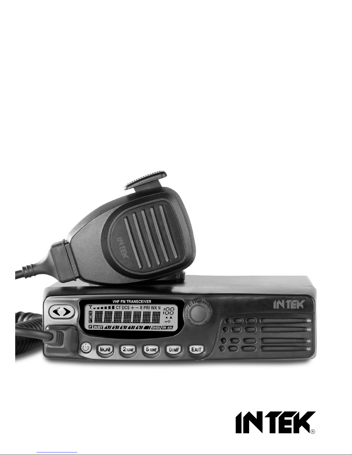
136-174 MHz VHF FM / 199CH / 10W-25W
PROFESSIONAL MOBILE RADIO
PC PROGRAMMABLE
MX-825V
400-470 MHz UHF FM / 199CH / 10W-25W
PROFESSIONAL MOBILE RADIO
PC PROGRAMMABLE
MX-825U
INSTRUCTION MANUAL
MANUALE DI ISTRUZIONI
Page 2

Index - Notice . . . . . . . . . . . . . . . . . . . . . . . . . . . . . . . . . . . . . . . . . . . . . . . . . . . . . . . . . . . . 1
General information - User Information . . . . . . . . . . . . . . . . . . . . . . . . . . . . . . . . . . . . . 2-3
Unpacking and checking parts - Supplied accessories . . . . . . . . . . . . . . . . . . . . . . . . . . 4
Installation . . . . . . . . . . . . . . . . . . . . . . . . . . . . . . . . . . . . . . . . . . . . . . . . . . . . . . . . . . . . . 5-6
Getting acquainted with the product . . . . . . . . . . . . . . . . . . . . . . . . . . . . . . . . . . . . . . . 7-10
Getting started . . . . . . . . . . . . . . . . . . . . . . . . . . . . . . . . . . . . . . . . . . . . . . . . . . . . . . . . . . 11
Menu Operation . . . . . . . . . . . . . . . . . . . . . . . . . . . . . . . . . . . . . . . . . . . . . . . . . . . . . . . 11-12
Advanced Functions . . . . . . . . . . . . . . . . . . . . . . . . . . . . . . . . . . . . . . . . . . . . . . . . . . . 12-17
Auxiliary Functions . . . . . . . . . . . . . . . . . . . . . . . . . . . . . . . . . . . . . . . . . . . . . . . . . . . . 18-19
Specifications - Optional Accessories . . . . . . . . . . . . . . . . . . . . . . . . . . . . . . . . . . . . . . . 20
Declaration of Conformity MX-825V . . . . . . . . . . . . . . . . . . . . . . . . . . . . . . . . . . . . . . . . . 43
Declaration of Conformity MX-825U . . . . . . . . . . . . . . . . . . . . . . . . . . . . . . . . . . . . . . . . . 44
Frequency / Channels Programming . . . . . . . . . . . . . . . . . . . . . . . . . . . . . . . . . . . . . . . . 45
Notes . . . . . . . . . . . . . . . . . . . . . . . . . . . . . . . . . . . . . . . . . . . . . . . . . . . . . . . . . . . . . . . . . . 46
Index - Notice
- 1 -
NOTICE !
This transceiver is programmable via PC, using the dedicated software (free download at
www.intek-radios.com) and the PC interface cable (optional item). Any programming or
modification of the original default setting must be made by a specialised technician or by an
authorised service centre. Some functions of this transceiver might be programmed in violation of
the technical rules in force for the use of the VHF and UHF FM bands. It is the user’s
responsibility to check that any modification to the programming will be done in compliance with
the current regulations. Any modification to the product, alteration of the internal circuit, of the
external structure of the radio or any programming in violation of the current regulations will
automatically void the product certification and your right to use the product. INTEK S.R.L.
declines any responsibility concerning any modification of the product, made by the user or by a
third party, after delivery of the product.
NOTICE !
This transceiver has been factory pre-programmed, in order for the user to test it right after
purchase. It is the user' s responsibility to re-program the radio, in accordance with the
specifications for the frequency channels assigned by the local authority.
NOTICE !
It is recommended to carefully read this owner’s manual before using the product. This will also
help the user to prevent using the radio in violation of the regulations valid in the country where
the product is used, as well as to avoid any possible interferences with other services.
English
Page 3
Thank you !
Thank you for choosing INTEK for your two-way business radios applications. This user friendly
transceiver will provide you with clear and reliable communications and will keep your professional
activities at peak efficiency. This transceiver incorporates the latest and most advanced technology, so
you will be pleased with its quality and its technical features.
Important notice !
The use of VHF and UHF FM transceivers is subject to the regulations applied in the country where the
product has to be used. As regulations are usually subject to possible modifications, please check the
current regulations in your country with your dealer or local supplier. INTEK does not take any
responsibility for illegal use and operation of this product not in accordance with the regulation of the
country where the product is used.
Safety notice
The user must know and understand the common risks related to the use of transceivers. Do not use
the transceiver in environments at risk of explosion (where there are gas, dusts, smokes, etc.). Do not
use the transceiver in service areas or fuel stations, on board aircrafts, etc.
Radio waves occurred by transmitting will interfere kinds of electronic equipment inside car (E.g. Antiskid braking systems, electronic ignition systems, electronic fuel injectors). Asking your dealer for help
to protect these equipments from interfering while transmitting, if your car is with these equipments.
Cautions
Please observe the following precautions, in order to avoid causing fire, personal injuries or damage to
the radio:
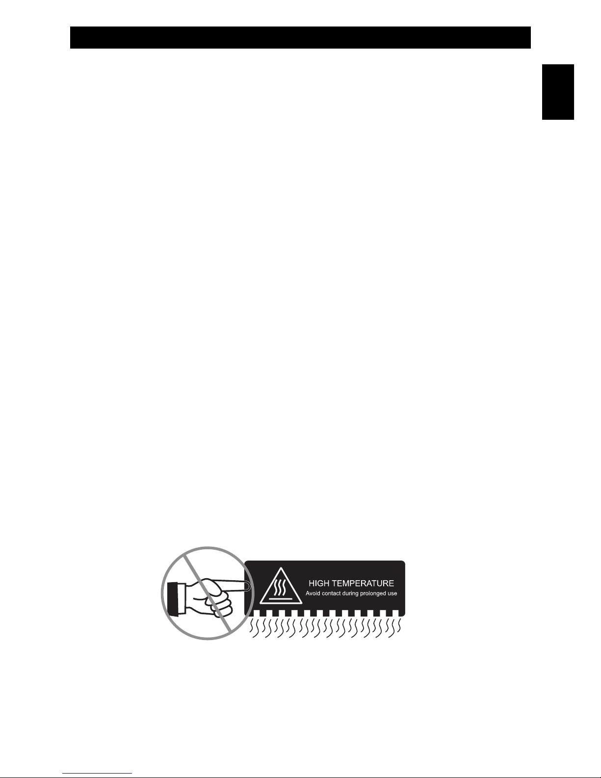
• Do not touch your transceiver metal surface while operating.
• Do not install the transceiver in the place which the body skin can close to the transceiver base.
• High temperature may make skin burns
- 2 -
General Information
English
Page 4

General Informations - User Information
- 3 -
GENERAL INFORMATIONS
• Do not attempt to operate your vehicle transceiver while driving. To avoid the high risk.
• Do not operate your transceiver while someone touching antenna or standing within 2-3 feet away
from antenna; it could protect you from burn or others hurt.
• Do not operate your transceiver within blast area or nearby blast primer
• Please turn OFF your transceiver when refueling or stopping at the gas station
• Do not modify your transceiver at any case.
• Do not expose the transceiver to direct sunlight of long periods, nor place it close to heating
appliances.
• Do not place the transceiver in excessively dusty, humid or wet areas, or on unstable surfaces.
• Do not attempt to dismantle your transceiver unless professional technical personnel.
• Please use the antenna and power cable with fuse specified by manufacturer or suppliers.
English
User Information
in accordance with art. 13 of the Legislative Decree of 25th July 2005, no. 15 ”Implementation of Directives 2002/95/EC,
2002/96/EC and 2003/108/EC, relative to reduction of the use of hazardous substances in electrical and electronic
equipment, in addition to waste disposal”.
The crossed bin symbol shown on the equipment indicates that at the end of its working life the product must
be collected separately from other waste.
The user must therefore take the above equipment to the appropriate differentiated collection centres for
electronic and electro technical waste, or return it to the dealer when purchasing a new appliance of
equivalent type, in a ratio of one to one.
Appropriate differentiated waste collection for subsequent recycling, treatment and environment-friendly disposal of the
discarded equipment helps to prevent possible negative environmental and health effects and encourages recycling of
the component materials of the equipment.
Illegal disposal of the product by the user will be punished by application of the administrative fines provided for by the
legislative decree no. 22/1997 (article 50 and following of the legislative decree no. 22/1997).
Page 5
Unpacking and Checking Parts - Supplied Accessories
- 4 -
Unpacking and checking parts
Carefully unpack the product. Please identify all the parts listed below, before wasting the packaging. If
any part is missing or if the packaging shows any damage, please contact your dealer immediately.
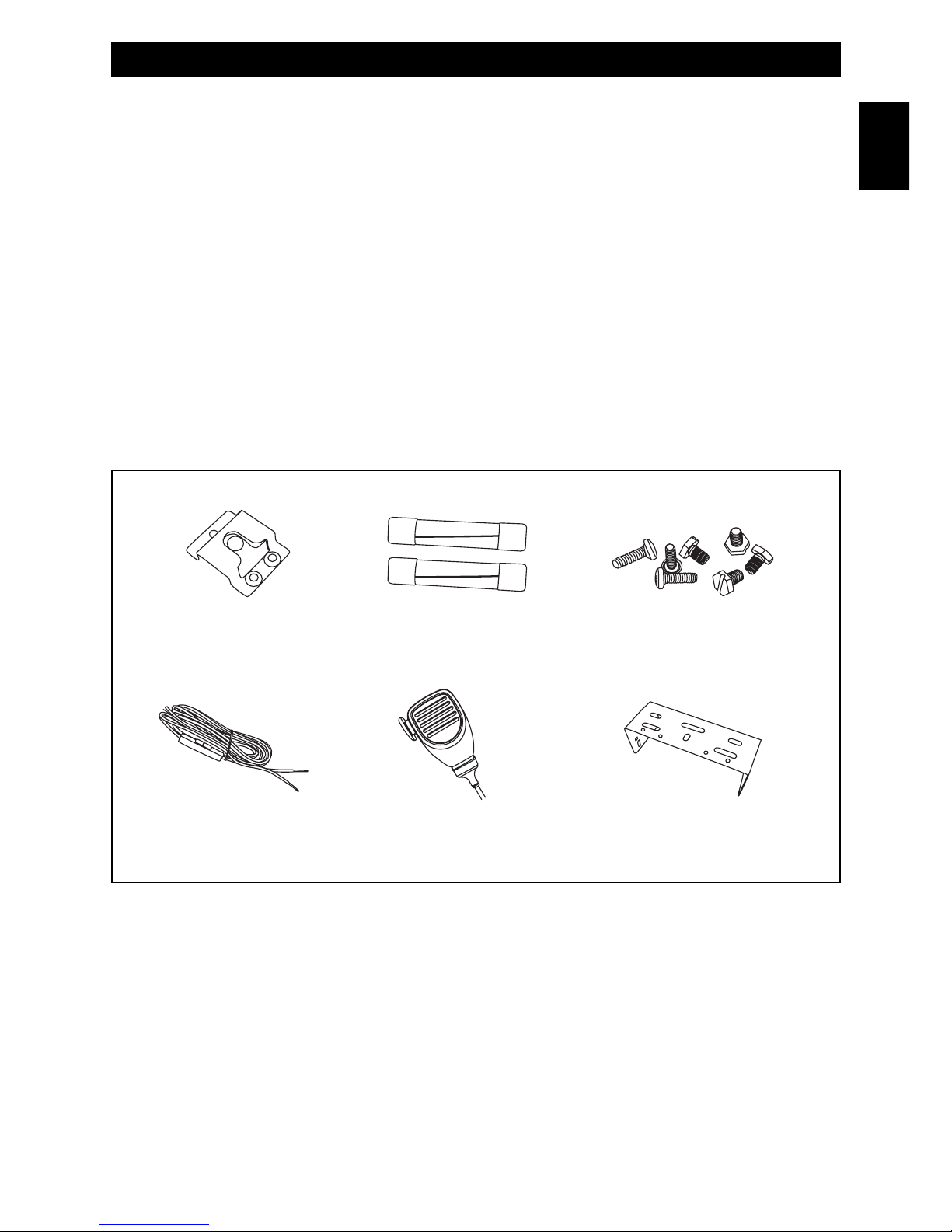
Supplied accessories
Microphone
Microphone Hanger
Fixed Bracket
Power Cable
Screws
Protective Tube
User Manual
English
Protective FuseMicrophone Hanger Screws
Power Cable Microphone Fixed Bracket
Page 6
INSTALLATION
Transceiver Installation
To install the transceiver, select a safe, convenient location inside your vehicle that minimizes danger to
your passengers and yourself while the vehicle is in motion. Consider installing the unit at an
appropriate position so that knees or legs will not strike it during sudden braking of your vehicle. Try to
pick a well ventilated location that is shielded from direct sunlight.
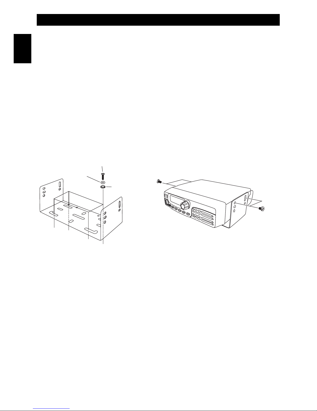
1. Install the mounting bracket in the vehicle using the supplied self-tapping screws, flat washers,
and spring washers.
2. Position the transceiver, then insert and tighten the supplied hexagon SEMS screws and flat
washers.
• Double check that all hardware is tightened to prevent vehicle vibration from loosening the
bracket or transceiver.
• Determine the appropriate angle of the transceiver, using the 3 screw hole positions on the
side of the mounting bracket.
DC Power Cable Connection
The vehicle battery must have a nominal rating of 12V. Never connect the transceiver to a 24V battery.
Be sure to use a 12V vehicle battery that has sufficient current capacity. If the current to the transceiver
is insufficient, the display may darken during transmission, or transmit output power may drop
excessively. This unit can only work under power system which is 13.8 ± 15%V negative ground.
1. Route the DC power cable supplied with the transceiver directly to the vehicle’s battery terminals
using the shortest path from the transceiver.
• If using a noise filter, it should be installed with an insulator to prevent it from touching metal on
the vehicle.
• We recommend you do not use the cigarette lighter socket as some cigarette lighter sockets
introduce an unacceptable voltage drop.
• The entire length of the cable must be dressed so it is isolated from heat, moisture, and the
engine secondary (high voltage) ignition system / cables.
2. After the cable is in place, wrap heat-resistant tape around the fuse holder to protect it from
moisture and tie down the full run of cable.
Installation
- 5 -
English
Self-tapping Screw
SpringWasher
Flat Washer
SEMS Screw
Page 7

- 6 -
Installation
3. To prevent the risk of short circuits, disconnect other wiring form the negative (-) battery terminal
before connecting the transceiver.
4. Confirm the correct polarity of the connections, then attach the power cable to the battery
terminals; red connects to the positive (+) terminal and black connects to the negative (-) terminal.
• Use the full length of the cable without cutting off excess even if the cable is longer than
required. In particular never remove the fuse holders from the cable.
5. Reconnect any wiring removed from the negative terminal.
6. Connect the DC power cable to the transceiver’s power supply connector.
• Press the connectors firmly together until the locking tab clicks.
Replacing Fuses
If the fuse blows, determine the cause, then correct the problem. After the problem is resolved, replace
the fuse. If newly installed fuses continue to blow, disconnect the power cable and contact your
authorized dealer or an authorized service center for assistance.
CAUTION
Only use fuses of the specified type and rating; otherwise the transceiver could be damaged.
Antenna Connection
Before operation, install an efficient, well-tuned antenna. The success of your installation will depend
largely on the type of antenna and its correct installation. The transceiver can give excellent results if
the antenna system and its installation are given careful attention.
Use a 50 Ohm impedance antenna and low-loss coaxial feed line that has a characteristic impedance
of 50 Ohm, to match the transceiver input impedance.
Coupling the antenna to the transceiver via feed lines having an impedance other than 50 Ohm reduces
the efficiency of the antenna system and can cause interference to nearby broadcast television
receivers, radio receivers, and other electronic equipment.
CAUTION
• Transmitting without first connecting an antenna or other matched load may damage the
transceiver. Always connect the antenna to the transceiver before transmitting.
• All fixed stations should be equipped with a lightning arrester to reduce the risk of fire, electric
shock, and transceiver damage.
English
Page 8
Getting Acquainted with the Product
- 7 -
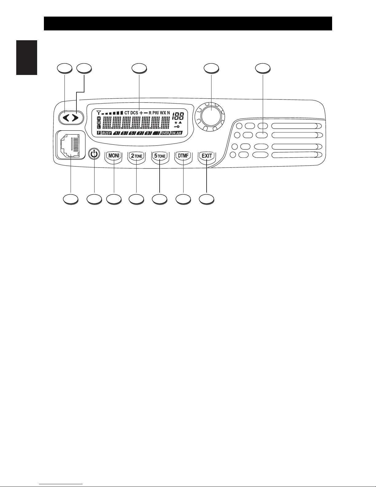
Front Panel
1. Down Key
This key allows adjust the volume level downward. By keeping this key pressed, the quick volume level selection
mode will be enabled.
2. Up Key
This key allows to select the operating channel upward. By keeping this key pressed, the quick volume level
selection mode will be enabled.
3. LCD Display
Backlighted Dot Matrix LCD Display, provides clear reading and full information on every function
and status of the radio
4. Menu/Confirmation Key / Rotary Switch
In Stand-by Mode use this knob to select the desired Channel/Zone.
Press this knob to enter the MENU Mode and to confirm the menu selections. In MENU Mode,
tune this knob to select the several MENU functions and options.
Press and hold this knob to start the scanning functions.
5. Speaker
Built-in speaker.
6. EXIT
Press this key to exit the MENU Mode and return to Stand-By status.
7. DTMF Key
Press this key to enter DTMF Mode. Use Rotary Switch (4) to select the desired DTMF group.
1 2
12 11 10 9 8 7 6
3 4 5
English
Page 9
- 8 -
Getting Acquainted with the Product
8. 5 TONE Key
Press this key to enter 5-Tone Mode. Use Rotary Switch (4) to select the desired 5-Tone group.
9. 2 TONE Key
Press this key to enter 2-Tone Mode. Use Rotary Switch (4) to select the desired 2-Tone group.
10. MONITOR Key
Press this key to open the Squelch, in order to hear the background noise and release it to close
the Squelch.
11. Power ON/OFF Key
Press this key to switch ON the radio. Press and hold this key to switch OFF the radio.
12. Microphone Connector
Connect the microphone to this connector.
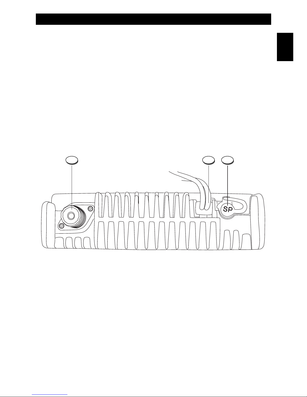
Rear Panel
13. ANTENNA Connector (SO-239)
Antenna connector. Refer to the section "ANTENNA CONNECTION" at page 6.
14. 13.2VDC POWER CORD
13.2VDC power cord input. The power cord is complete with fuse.
15. EXT (External Speaker) Jack
This jack is for connecting an external speaker (optional).
13 14 15
English
Page 10
- 9 -
Getting Acquainted with the Product
A. Signal Digital Bar Meter
Indicates the received signal strenght in the receive mode.
B. CT Icon
The CT Icon (B) is lighted when the CTCSS function is enabled. Please refer to CTCSS/DCS
function at page 15.
C. DCS Icon
The DCS Icon (C) is lighted when the DCS function is enabled. Please refer to CTCSS/DCS
function at page 15.
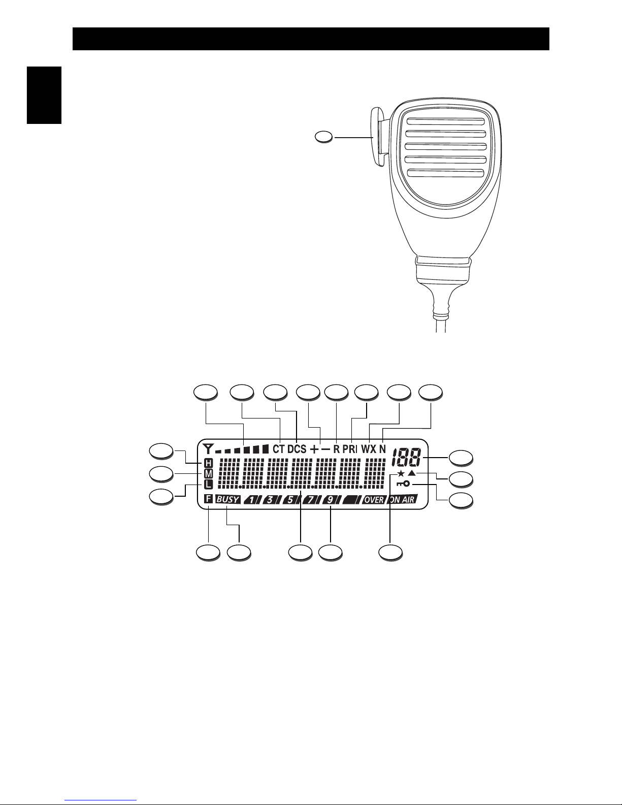
16. PTT (Push-to-Talk) Key
Transmitter key. Press the PTT key (16) to
transmit and release it to return to the receive
mode.
English
A B DC E
R P O NQ
F G H
I
L
M
T
U
S
16
LCD Display
Microphone
Page 11

- 10 -
Getting Acquainted with the Product
D.
+ -
Icons
Not available on this model.
E. R Icon
This icon is lighted when the Reverse Frequency function is enabled. Please refer to REVERSE
FREQUENCY FUNCTION at page 13.
F. PRI Icon
This icon is lighted when the Priority Scan function is enabled. Please refer to PRIORITY SCAN
FUNCTION at page 14.
G. WX Icon
Not available on this model
H. Narrow Bandwidth Icon
This icon shows the 12.5 KHz bandwidth.
I. Numerical Indication
This indication shows the last two digits of the frequency channel (P). When the Dot Matrix Indication
(P) shows the channel number, this Numerical Indication (I) shows the Zone Number.
When the Dot Matrix Indication (P) shows the Zone Number or Channel Name, this Numerical
Indication (I) shows the Channel Number.
L. Channel Scanning Icon
This Icon is lighed when the selected channel is programmed to the scanning list.
M. Keypad Lock Icon
The Lock icon (M) is lighted when the keypad lock function has been enabled.
N. Auto Resume Icon
This Icon is lighed when the Tone Decode Auto Resume function is enabled.
O. RF Digital Meter
It indicates the transmitter RF output power.
P. Dot Matrix Indication
It provides full information on channel and all enabled functions.
Q. BUSY Icon
This Icon is lighed when the selected channel is busy.
R. F Icon
Not available on this model.
S. L Icon
The L icon (S) is lighted when the transmitter is in Low Power mode.
T. M Icon
The M icon (T) is lighted when the transmitter is in Middle Power mode.
U. H Icon
The H icon (U) is lighted when the transmitter is in High Power mode.
Page 12

- 11 -
Getting Started - Menu Operation
GETTING STARTED
Power ON
Switch on the transceiver by pressing the ON/OFF Key (11); the Welcome indication (P) appears on
the LCD display (3) and radio now is in Stand-by Mode.
Press and hold the ON/OFF Key (11) to switch OFF the radio.
Volume adjustment
Press or hold the DOWN key (1) to decrease the volume level and press or hold the UP key (2) to
increase the volume level. Press the MONITOR key (10) to listen to the background noise of the
channels while adjusting the volume to a comfortable level.
Transmission
In order to transmit, press the PTT key (16) and speak with your normal voice, keeping the microphone
(16) at about 4 cm from your mouth. The RF Digital Meter (O) will show the transmitter RF output
power. Release the PTT Key (16) at the end of transmission.
Note : If you continuously transmit for longer than the time specified in internal TOT, the transceiver will
generates a warning beep and stops transmitting. In this case, release PTT key (16) and let the
transceiver cool down for a moment, then press PTT key (16) again to resume transmission.
Receiving
Release the PTT key (16) and properly adjusting volume, you will be able to receive the incoming signals.
When receiving a signal, the BUSY Icon (Q) appears on LCD Display (3). For operating the
CTCSS/DCS, DTMF, 2-Tone or 5-Tone functions, refer to special sections.
Channel selection
Select the desired channel, using the Rotary Switch (4). In NAME Mode the LCD display (3) will show
the Channel Name. 199 channels are available.
Channel Mode / Name Mode
Press MENU Key (4) to enter the MENU Mode and select the MODE function. Use the Rotary Switch
(4) to select CH NO. (Channel Mode) or CH NAME (Name Mode). Press MENU key (4) to confirm
selection and return to Stand-by mode.
MENU OPERATION
Many functions on this radio, may be enabled or configured only by using the PC programming
software.
To access the MENU Mode and operating the menu options, please proceed as follow :
1. Press MENU Key (4) to enter the MENU Mode; the MODE indication (P) will appear on LCD display (3).
2. Use the Rotary Switch (4) to select the desired menu function.
3. Confirm the selected function by pressing the MENU Key (4).
4. Use the Rotary Switch (4) to select the desired function setup/option.
5. Press the MENU Key (4) to confirm the selected setup/option or press the EXIT Key (6) to return
to menu function selection.
6. Press any key, except MENU key (4), Power ON/OFF key (11) and Volume keys (1/2) to exit the
MENU mode and return to Stand-by mode.
Page 13

Menu Operation - Advanced Functions
- 12 -
Menu function sequence
MODE (Operating modes) ---> TX.POW (transmitter power High-Middle-Low) --> SQH.LEV (Squelch
Level) --> SQH.MOD (Squelch modes) --> ZONE (Zone selection) --> MONI (Monitor modes) --> TOT
(Time Out Timer) --> SCN.MO (Scan modes) --> SCN.TY (Scan Type) --> REVERSE (Reverse
Frequency) --> BRIGHT (LCD DIsplay Brightness) --> K.TONE (Keypad Tone ON/OFF) --> S.TONE
(Side Tone ON/OFF) --> BEEP (Beep Tone ON/OFF) --> SCN.ADD (channel scanning add or remove) -
-> CTC/DCS (CTCSS/DCS Setup) --> COMPAND (Compander ON/OFF) --> EMPH (Emphasis
ON/OFF) --> CH.DEL (Channel Deletion Setup) -->TEMP (Temperature Adjusting ON/OFF)
ADVANCED FUNCTIONS
Zone Mode / Zone Selection
Zone Mode
Press MENU Key (4) to enter the MENU Mode and select the MODE function. Use the Rotary Switch
(4) to select ZO NO. (Zone Number) or ZO NAME (Zone Name) modes. Press MENU key (4) to confirm
selection and return to Stand-by mode.
Zone Selection
Press MENU Key (4) to enter the MENU Mode. Use the Rotary Switch (4) to select ZONE function and
press MENU Key (4) to confirm the selection. Use the Rotary Switch (4) to select the desired Zone
Number and confirm by pressing the MENU Key (4). Press EXIT Key (6) to return to Stand-by mode.
In CHANNEL MODE or NAME MODE, the numerical indication (I) will indicate the selected zone
number. 32 zones are available.
Channel Deletion
Select the channel to remove and enter the MENU Mode. Enter the CH.DEL function setup and select
CANCEL (cancel the operation) or SURE (confirm and delete the selected channel). When user selects
SURE option, the SURE! indication appears on LCD display and the channel will be deleted then radio
returns to Stand-by mode.
Monitor Function
This function opens Squelch in order to listen to the background noise and weak signals. The Monitor
function has 4 available options. In MENU mode enter the MONI function setup and use Rotary Switch
(4) to select the desired option as follow :
MONI A (Tone Squelch Invalidation-Instantaneous)
If this option is selected, press and hold MONI key (10) to open squelch on channels with CTCSS/DCS,
DTMF, 2/5-Tone and release this key to close squelch.
MONI B (Tone Squelch Invalidation-Trigger)
If this option is selected, press MONI key (10) to open squelch on channels with CTCSS/DCS, DTMF, 2/5Tone and press again this key to close squelch.
MONI C (Carrier Squelch Invalidation-Instantaneous)
If this option is selected, press and hold MONI key (10) to open squelch and release this key to close
squelch.
MONI D (Carrier Squelch-Trigger)
If this option is selected, press MONI key (10) to open squelch and rand press again this key to close
squelch.
Press MENU Key (4) to confirm the desired option and press EXIT key to return to Stand-by mode.
Page 14

Keypad Lock
Press the Power ON/OFF Key (11) then the EXIT Key (6) to lock the keypad; the Keylock Icon (M) will
appear on LCD Display (3). Repeat the same procedure to unlock the keypad; he Keylock Icon (M) will
disappear on LCD Display (3).
Transmitter Output Power Setup
In MENU mode enter the TX.POW function setup and use Rotary Switch (4) to select the desired
transmitter output RF power as LOW (Low Power), MID (Middle Power) or HIGH (High Power). Press
MENU Key (4) to confirm the selection and press the EXIT Key (6) to return to Stand-By Mode or use
Rotary Switch (4) to select other functions.
The selected transmitter output power is indicated on LCD display (3); L (S) for Low Power, M (T) for
Middle Power and H (U) for High Power.
Note : On any channel it is possible select different RF power level, by using the PC software.
Reverse Frequency Function
When dual frequency is used to start reverse frequency function, the receiving frequency and emission
frequency will interchange on selected channel (it is possible only by using the PC software). In MENU
Mode, enter the REVERSE function setup and use Rotary Switch (4) to select ON (function enabled) or
OFF (function disabled). When the REVERSE function is enabled, the R Icon (E) appears on LCD
Display (3).
Scan Function
Scan Type
In MENU mode enter the SCN.TY function setup and use Rotary Switch (4) to select SCN.ZO or
SCN.CH options.
SCN.ZO : radio will scan all channels in the selected zone.
SCN.CH: radio will scan all channels in all zones.
Press MENU Key (4) to confirm the desired option and press the EXIT Key (6) to return to Stand-By
Mode or use Rotary Switch (4) to select other functions.
Start Scanning
Press and hold the MENU Key (4) to start scanning function; the SCAN indication (P) will appear on
LCD Display (3).
Note : This function can operate only if scanning list contains two or more channels. Please refer to
Channel Scanning Addition / Deletion function at page 14.
Stop Scanning
Scanning function will be stopped or paused in the following conditions :
1. By pressing the MENU Key (4); the SCAN indication (P) will disappear from LCD Display (3).
2. By pressing the MONI key (10); radio will resume scanning function after 3 seconds, if MONITOR
Key (10) is released.
3. A channel without an associated CTCSS/DCS tone receives the carrier wave.
4. A channel with an associated CTCSS/DCS tone receives the carrier wave and the same tone.
Scan Mode
In MENU mode enter the SCN.MO function setup and use Rotary Switch (4) to select TIMER or
CARRIER options.
Advanced Functions
- 13 -
Page 15

Advanced Functions
- 14 -
TIMER SCAN : If this option is selected, SCAN will automatically stop when a signal is detected on one
channel, and re-start automatically after a programmed time.
CARRIER SCAN : If this option is selected, SCAN will automatically stop when a signal is detected on
one channel, in order to listen to the communication and SCAN will re-start when no more signal is
detected on that channel.
Note : The TIMER SCAN TIME is programmable with the PC software.
Press MENU Key (4) to confirm the desired option and press the EXIT Key (6) to return to Stand-By
Mode or use Rotary Switch (4) to select other functions.
Channel Scanning Addition / Deletion
Select the channel to be added to the scanning list. Enter the MENU Mode, select the SCN.ADD
function setup and press MENU Key (4) to confirm. Use the Rotary Switch (4) to select the following
options :
ADD : the selected channel will be added to the scanning list; the Channel Scanning Icon (L) will appear on
the LCD display (3).
DEL : the selected channel will be removed from the scanning list; the Channel Scanning Icon (L) will
disappear from the LCD display (3).
Press MENU Key (4) to confirm the desired option and press the EXIT Key (6) to return to Stand-By
Mode or use Rotary Switch (4) to select other functions.
Priority Scan Function
If a Priority Channel has been programmed, during scan function, radio will check periodically this
channel for incoming signals. When a signal is received on this channel, radio will switch automatically to
priority channel and the PRI Icon (F) will appear on LCD Display (3).
Note : This function is totally programmed by PC software and it is available only in CHANNEL MODE.
Priority Channel Cancel Temporarily
When the Scan function stops on Priority Channel, press EXIT key (6) to temporarily remove the priority
channel.
Note : When user exit the Scan function, the removed Priority Channel will be resumed.
Channel Scanning Cancel Temporarily
User can temporalily remove a channel from scanning list. When Scan Function stops on an unwanted
channel, press EXIT Key (6) to temporarily delete this channel from the scanning list.
The Scan function will resume immediately.
Note : When user exit the Scan function, Channel removed from scanning list will be resumed.
Reply Channel
During Scanning process, press PTT key (16) to stop the scan and switch to reply channel.
Note : This function may be enabled by using the PC software.
Scan Trasmitting / Receiving Resume Delay
When Scan stops on one channel, it will re-start only when the delay time is expired, even if incoming
signals disappear.
Note : The Delay Time may be programmed by using the PC software.
Page 16

- 15 -
Advanced Functions
Decode Continuance Time
During Scan process, when a signal is detected on one channel, if transceiver can' t decode
successfully, it will resume to scan next channel.
Note : This function is programmed by PC software and it is available only in CHANNEL MODE.
CTCSS / DCS FUNCTION
Any channel may be associated to a programmed private protection CTCSS/DCS tone. A CTCSS/DCS
tone is a sub audible tone which allows to cut off and therefore not to listen to signals transmitted from
other users on the same operating channel.
When you receive a signal which has a tone different from the one which has been programmed on
your radio, you will not listen to this signal. For the same reason, your outgoing messages can only be
received by other radios which have the same tone as yours on that channel.
Note : Even if the use of a CTCSS/DCS tone will protect you from receiving unwanted signals, the
privacy of your transmissions is not guaranteed.
50 CTCSS tones and 83 DCS groups are available.
CTCSS / DCS Encode
To transmit a signal with a CTCSS or a DCS Tone, enter the MENU Mode and select the CTC/DCS
function setup. Select and confirm the ENCODE option and use the Rotary Switch (4) to select the
desired CTCSS or DCS tone number or select OFF to disable the function.
Press MENU Key (4) to confirm the desired tone number and press the EXIT Key (6) to return to
CTC/DCS function setup. Press the EXIT Key (6) again to return to Stand-by mode.
CTCSS / DCS Decode
To receive a channel which has a CTCSS or a DCS Tone associated, enter the MENU Mode and select
the CTC/DCS function setup. Select and confirm the DECODE option and use the Rotary Switch to
select the desired CTCSS or DCS tone number or select OFF to disable the function.
Press MENU Key (4) to confirm the desired tone number and press the EXIT Key (6) to return to
CTC/DCS function setup. Press the EXIT Key (6) again to return to Stand-by mode.
When a CTCSS or DCS decode tone is selected, the CT (B) or DCS (C) Icons wiil appear on LCD
Display (3).
2-TONE / 5-TONE / DTMF
Many repeaters can be activated by sending 2-Tone / 5-Tone / DTMF codes. For further information,
consult your local dealer.
Note : These functions are programmable by using the PC software.
2-Tone
Press 2-Tone Key (9) to enter 2-Tone mode and use the Rotary Switch to select the desired 2-Tone code
(32 groups maximum).
Press PTT Key (16) to transmit the selected tone directly. To EXIT the 2-Tone Mode, press EXIT Key (6).
5-Tone
Press 5-Tone Key (8) to enter 5-Tone mode and use the Rotary Switch to select the desired 5-Tone code
(32 groups maximum).
Press PTT Key (16) to transmit the selected Tone directly. To EXIT the 5-Tone Mode, press EXIT Key (6).
English
Page 17

- 16 -
Advanced Functions
DTMF (Dual Tones Multi-Frequency)
Press DTMF Key (7) to enterDTMF mode and use the Rotary Switch to select the desired DTMF code
(32 groups maximum).
Press PTT Key (16) to transmit the selected Tone directly. To EXIT the DTMF Mode, press EXIT Key (6).
SQUELCH SETTING
This function allows to silent the receiver by cutting the background noise, when no signals are
received.
Squelch Level Selection
The Squelch threshold level is adjustable in 10 levels, from 0 to 9. Enter the MENU Mode and select
the SQH.LEV function setup. Press MENU Key (4) to confirm and use the Rotary Switch to select the
desired Squelch Threshold level, from SQL-0 (Squelch open) to SQL-9 (lowest Squelch sensitivity).
Press MENU Key (4) to confirm the selection and press the EXIT Key (6) to return to Stand-By Mode or
use Rotary Switch (4) to select other functions.
Squelch Mode Selection
Enter the MENU Mode and select the SQH.MOD function setup. Press MENU Key (4) to confirm and
use the Rotary Switch to select the desired option. The available Squelch modes are : CARRIER,
CT.DCS, OPT.SIG, AND, OR.
1. CARRIER (Carrier Wave) : When radio receives an incoming signal which reach the squelch
level, the Squelch will open.
2. CT.DCS (CTCSS / DCS) : This mode is available only when the selected channel has a CTCSS
or DCS tone associated. Only the CTCSS / DCS succeed in decoding, radio can open squelch.
3. OPT.SIG (2-Tone / 5-Tone / DTMF) : This mode is available only when the selected channel is in
2-Tone, 5-Tone or DTMF mode. Only the 2/5-Tone / DTMF succeed in decoding, the transceiver
can open squelch.
4. AND (2-Tone / 5-Tone / DTMF and CTCSS / DCS) : This mode is available only when the
selected channel is in 2-Tone, 5-Tone or DTMF mode and CTCSS/DCS mode.
Only the 2-Tone/5-Tone / DTMF and CTCSS / DCS succeed in decoding, radio can open squelch.
5. OR (2-Tone / 5-Tone / DTMF or CTCSS / DCS) : This mode is available only when the selected
channel is in 2-Tone, 5-Tone or DTMF mode or CTCSS/DCS mode. Only the 2/5-Tone / DTMF or
CTCSS / DCS succeed in decoding, the transceiver can open squelch.
Press MENU Key (4) to confirm the selection and press the EXIT Key (6) to return to Stand-By Mode or
use Rotary Switch (4) to select other functions.
Auto Resume Time
Set radio in 2/5-Tone or DTMF Mode and set the Squelch Mode to include 2/5-Tone / DTMF (refer to
Squelch Mode Selection). When the signal on selected channel disappear, radio will enter automatically
the receiving mode again within Auto Resume Time.
Encoding Squelch
If the transceiver doesn' t receive the correct and suited encoding mode (2/5-Tone / DTMF), user can' t
reply the call.
1. RECEIVING
When radio receives a signal which has same 2-Tone / 5-Tone / DTMF codes as selected channel,
Squelch will be open in order to receive the communication.
English
Page 18

- 17 -
Advanced Functions
English
2. TRANSMITTING
• Press 2-Tone (9), 5-Tone (8) or DTMF key (9) to enter encoding menu item.
• Use the Rotary Switch (4) to select the desired encoding group (1-32).
• Press and hold the PTT key (16) to transmit the desired encoding tones.
• Release the PTT Key (4) to cut off the encoding squelch.
TOT (Time Out Timer) SETTING
This function has two purposes :
1. to allow, after a set time, to listen to other urgent calls.
2. avoid to transmit for an endless time, in order to prevent overheating or damage to the
transceiver. After a programmable time of 15-1200 seconds (default setting is 180 seconds) of
uninterrupted transmission, the transceiver automatically stops the transmission emitting a warning tone
(pre-set function). To stop the warning tone, release the PTT key (16). To restart the transmission, press
again the PTT key (16).
To set up this function, enter MENU mode and select the TOT function. Confirm the selection by
pressing the MENU Key (4) and use the Rotary Switch (4) to select the desired TOT Time, from 15 to
1200 seconds or select OFF to disable the function.
Confirm the selection by pressing the MENU Key (4) and press the EXIT Key (6) to return to Stand-by
Mode.
TOT Pre-Alarm
The transceiver can setup the pre-alarm TOT (1-10s). Before 1-10s of TOT, the transceiver will sound a
beep.
TOT Delay Time
When the transmission exceeds the TOT setting, you can transmit again within TOT delay time (from 1
to 60 seconds).
Note : This function is programmed by PC software
TOT Resume Time
The transceiver can setup the TOT resume time (1-15s). Before exceeding TOT, within resume time, if
you transmit again, the TOT will resume to add up the time. Or else the TOT will restart to record the
time.
Auto Resume to Main Channel
Set up a main channel by using PC software (the other channels will be secondary channels). In MENU
mode enter HOCH function and select ON to activate it. No matter in which channel you receive /
transmit, some seconds later (set by PC software), the radio will auto-resume to the main channel.
If no main channel is set, this function can not operate. If HOCH function is set as OFF (disabled), radio
can not auto-resume to main channel either even main channel is set.
Talk Around (Repeater channels only)
When this function is enabled, the RX frequency will be same as TX frequency. If CTCSS/DSC is set, the
encoding will become decoding.
In Menu mode, enter TALK.AR function and rotate the knob (4) to select OFF (function disabled) or ON
(function enables). Press MENU key (4) to confirm and press EXIT key (6) to return to standby mode.
Page 19

Auxiliary Functions
- 18 -
English
AUXILIARY FUNCTIONS
Busy Channel Lockout
This function prevents interferences of other incoming signals. If the selected channel is busy and the
Busy Channel Lockout function has been enabled, the trasmission is disabled.
When this function is enabled and the selected channel is Busy, if user press PTT Key (16), an alarm
will be emitted.
Note : This function is programmable by using the PC software.
LCD and Keypad Backlight
Enter the MENU Mode and select the BRIGHT function setup. Press MENU Key (4) to confirm and use
the Rotary Switch to select the AUTO, OFF or ON options.
AUTO : The display LCD and Keypad backlight will be enables if any key is pressed and will be disabled
after 10 seconds if no keys are pressed.
ON : The display LCD and Keypad backlight will be enabled.
OFF : The display LCD and Keypad backlight will be disabled.
Confirm the selection by pressing the MENU Key (4) and press the EXIT Key (6) to return to Stand-by
Mode.
SCRAMBLER Function
This function is not available on this model.
COMPANDER Function
This function allows to obtain a stronger, clear and clean audio signal and it is a great help in noisy
areas and in case of weak signals or in long distance communication.
To enable the COMPANDER function please proceed as follows :
Enter the MENU Mode and select the COMPAND function setup. Press MENU Key (4) to confirm and
use the Rotary Switch to select the OFF (function disabled) or ON (function enabled) options.
Confirm the selection by pressing the MENU Key (4) and press the EXIT Key (6) to return to Stand-by
Mode.
Emphasis Function
Enter the MENU Mode and select the EMPH function setup. Press MENU Key (4) to confirm and use
the Rotary Switch (4) to select the OFF (function disabled) or ON (function enabled) options.
Confirm the selection by pressing the MENU Key (4) and press the EXIT Key (6) to return to Stand-by Mode.
SOS Function
Press and hold the EXIT key (6) to turn ON (function enabled) or OFF this function. After SOS signal is sent, it
issues a roger beep “DI”.
Options can be programmed by using PC software :
A. Local alarm (alarm time can be set via software)
B. Transmit ENI and background sound (no local alarm)
C. Transmit ENI and alarm sound (no local alarm)
D. Transmit ENI and alarm sound (with local alarm)
Page 20

Beep Function
Enter the MENU Mode and select the BEEP function setup. Press MENU Key (4) to confirm and use
the Rotary Switch to select the OFF (function disabled) or ON (function enabled) options.
Confirm the selection by pressing the MENU Key (4) and press the EXIT Key (6) to return to Stand-by
Mode.
Note : It is reccomended to leave this function enabled (ON) in order to detect erroneous operations
and malfunctions of the radio.
Keypad Tone Setup
When a key is pressed, a beep tone is heard to confirm your command. The user may enable or disable
this keypad program tone. Enter the MENU Mode and select the K.TONE function setup. Press MENU
Key (4) to confirm and use the Rotary Switch to select the OFF (function disabled) or ON (function
enabled) options.
Confirm the selection by pressing the MENU Key (4) and press the EXIT Key (6) to return to Stand-by
Mode.
Side Tone Setup
Enter the MENU Mode and select the S.TONE function setup. Press MENU Key (4) to confirm and use
the Rotary Switch to select the OFF (function disabled) or ON (function enabled) options.
Confirm the selection by pressing the MENU Key (4) and press the EXIT Key (6) to return to Stand-by
Mode.
Note : The Beep volume level is programmed by PC software
Temperature Adjust Power
Press MENU key (4) to enter MENU mode and select TEMP function. Use the Rotary Switch (4) to
select the OFF (function disabled) or ON (function enabled) options and confirm the selection by
pressing the MENU key (4). This function can protect the transceiver overheat. When the temperature is
higher than 100°C, the transceiver will auto adjust the TX power to be LOW. When the temperature is
higher than 125°C, the transceiver will auto stop the transmission.
Wide / Middle / Narrow bandwidth Selection (*)
Press MENU key (4) to enter Menu mode and select B.WIDTH function. Use the Rotary Switch (4) to
select WIDE, MIDDLE or NARROW bandwidth and confirm the selection by pressing the MENU key (4).
(*) This features are subject to the regulations applied in the country where the product is used.
- 19 -
Auxiliary Functions
English
Page 21

SPECIFICATIONS
General
Frequency VHF 136-174 MHz (MX-825V)
UHF 400-470 MHz (MX-825U)
Channels 199
Channel spacing 12.5 / 20 / 25 KHz
DC input voltage 13.8 VDC +/- 15%
Operating temperature -20/+55°
Dimensions L 158 x H 40 x D 155 mm
Weight 1140 gr.
Receiver
Sensitivity (12dB Sinad) 0.16 µV
Selectivity ≥60dB
Audio output 500mW
Transmitter
RF output power 25W / 10W (*)
Modulation F3E
Spurious & Harmonics in compliance with the R&TTE regulations
Maximum deviation ≤ +/- 5KHz / ≤ +/- 2.5KHz
Frequency Stability +/- 2.5ppm
(*) This features are subject to the regulations applied in the country where the product is used.
OPTIONAL ACCESSORIES
KSPL-05 USB Type PC Interface Cable
Specifications - Optional Accessories
- 20 -
English
Page 22

Indice - Importante . . . . . . . . . . . . . . . . . . . . . . . . . . . . . . . . . . . . . . . . . . . . . . . . . . . . . . . 21
Informazioni per l' utente . . . . . . . . . . . . . . . . . . . . . . . . . . . . . . . . . . . . . . . . . . . . . . . . . . 22
Informazioni Generali - Avviso agli utenti . . . . . . . . . . . . . . . . . . . . . . . . . . . . . . . . . . . . 23
Disimballaggio e verifica delle parti - Accessori forniti . . . . . . . . . . . . . . . . . . . . . . . . . 24
Installazione . . . . . . . . . . . . . . . . . . . . . . . . . . . . . . . . . . . . . . . . . . . . . . . . . . . . . . . . . . 25-26
Familiarizzare con il prodotto . . . . . . . . . . . . . . . . . . . . . . . . . . . . . . . . . . . . . . . . . . . 27-30
Operazioni di base . . . . . . . . . . . . . . . . . . . . . . . . . . . . . . . . . . . . . . . . . . . . . . . . . . . . . . . 31
Utilizzo del menu . . . . . . . . . . . . . . . . . . . . . . . . . . . . . . . . . . . . . . . . . . . . . . . . . . . . . . . . 32
Funzioni avanzate . . . . . . . . . . . . . . . . . . . . . . . . . . . . . . . . . . . . . . . . . . . . . . . . . . . . . 32-38
Funzioni supplementari . . . . . . . . . . . . . . . . . . . . . . . . . . . . . . . . . . . . . . . . . . . . . . . . 39-40
Specifiche tecniche - Accessori opzionali . . . . . . . . . . . . . . . . . . . . . . . . . . . . . . . . . . . . 41
Avvertenze importanti - Garanzia limitata . . . . . . . . . . . . . . . . . . . . . . . . . . . . . . . . . . . . 42
Dichiarazione di Conformità MX-825V . . . . . . . . . . . . . . . . . . . . . . . . . . . . . . . . . . . . . . . 43
Dichiarazione di Conformità MX-825U . . . . . . . . . . . . . . . . . . . . . . . . . . . . . . . . . . . . . . . 44
Programmazione canali . . . . . . . . . . . . . . . . . . . . . . . . . . . . . . . . . . . . . . . . . . . . . . . . . . . 45
Note . . . . . . . . . . . . . . . . . . . . . . . . . . . . . . . . . . . . . . . . . . . . . . . . . . . . . . . . . . . . . . . . . . . 46
Indice - Introduzione
- 21 -
Italiano
IMPORTANTE !
Questo ricetrasmettitore è programmabile tramite PC, utilizzando l’apposito software
(liberamente scaricabile dal sito www.intek-radios.com) e cavetto di interfaccia (opzionale).
L’eventuale programmazione o modifica della programmazione esistente deve essere eseguita
da un tecnico specializzato o da un centro di assistenza autorizzato. Alcune funzioni del
ricetrasmettitore potrebbero essere programmate in violazione delle norme tecniche in vigore
per l’utilizzo delle bande VHF e UHF FM. E’ responsabilità dell’utente verificare che eventuali
modifiche nella programmazione delle funzioni del ricetrasmettitore siano conformi a quanto
previsto dalle norme tecniche in vigore. Modifiche al prodotto, manomissioni, alterazione delle
regolazioni interne o delle strutture esterne della radio e programmazioni in violazione delle
norme di legge fanno decadere le certificazioni e omologazioni del prodotto ed il diritto
all’utilizzo dello stesso.
INTEK s.r.l. declina qualsiasi responsabilità relativamente a modifiche della programmazione
del ricetrasmettitore, eseguite dall’utente o da terzi, dopo la consegna del prodotto.
IMPORTANTE !
Questo ricetrasmettitore è stato pre-programmato in origine, al fine di consentire un test del
prodotto dopo l’acquisto. E' responsabilità dell' utente riprogrammare la radio, nel rispetto delle
norme tecniche in vigore per l’ utilizzo sulle frequenze assegnate dalla autorizzazione ministeriale.
IMPORTANTE !
Si raccomanda di leggere attentamente questo manuale prima di utilizzare il prodotto. Ciò aiuterà
l' utente anche ad impedire di utilizzare la radio in violazione delle norme di legge in vigore nel
paese dove il prodotto viene utilizzato e di evitare ogni possibile interferenza con altri servizi.
Page 23

Grazie !
Vi ringraziamo per aver scelto INTEK per applicazioni civili. Siamo certi che questo ricetrasmettitore di
facile uso vi consentirà di comunicare in modo affidabile e di svolgere le vostre attività professionali con
la massima efficienza. Questo ricetrasmettitore incorpora la più avanzata tecnologia e sarete soddisfatti
del suo livello di qualità e delle sue caratteristiche tecniche.
Avviso importante per l' utente !
L’utilizzo dei ricetrasmettitori VHF e UHF FM è regolato dalle norme di legge in vigore. Poiché le norme
stesse sono soggette a possibili variazioni, prima di utilizzare gli apparecchi, si raccomanda di
informarsi presso il proprio rivenditore o fornitore verificando gli eventuali adempimenti da osservare.
INTEK declina qualsiasi responsabilità relativamente ad un uso degli apparecchi non autorizzato o non
conforme alle norme di legge.
Sicurezza
L’utente deve conoscere e comprendere i rischi comuni legati all’uso di apparecchi ricetrasmittenti. Non
utilizzate mai il ricetrasmettitore in ambienti a rischio di esplosione (in presenza di gas, polveri, fumi,
etc.). Non utilizzare inoltre il ricetrasmettitore nelle aree di servizio o distributori di carburante.
Le onde radio generate mediante la trasmissione possono interferire con i dispositivi elettronici all' interno dell'auto
(come sistemi di frenata anti-skid, sistemi di accensione elettronica, iniezione elettronica, ecc.). Chiedere al proprio
rivenditore informazioni su come proteggere questi dispositivi da interferenze durante la trasmissione, se il veicolo ne
fosse provvisto.
Precauzioni
Si consiglia di osservare le seguenti precauzioni, al fine di evitare incendi, ferite personali e danni al
ricetrasmettitore:
• Non toccare la superficie di metallo del ricetrasmettitore durante il funzionamento.
• Non installare il ricetrasmettitore in una posizione in cui la pelle del corpo possa avvicinarsi o
toccare la base del ricetrasmettitore.
• La temperatura elevata del ricetrasmettitore può causare ustioni alla pelle.
- 22 -
Informazioni per l' utente
Italiano
Page 24

- 23 -
Italiano
Informazioni Generali - Avviso agli utenti
INFORMAZIONI GENERALI
Avvisi per l' utente
•
Non azionare il ricetrasmettitore durante la guida del veicolo.
• Non utilizzare il ricetrasmettitore mentre qualcuno tocca l' antenna o si trova nelle immediate vicinanze.
• Non utilizzare il ricetrasmettitore in presenza di sostanze infiammabili
• Spegnere il ricetrasmettitore durante il rifornimento e sosta al distributore di carburante
• Non aprire o modificare il ricetrasmettitore in nessun caso.
• Non esporre il ricetrasmettitore alla luce diretta del sole per lunghi periodi di tempo, né collocarlo in prossimità
di apparecchi di riscaldamento.
• Non collocare il ricetrasmettitore in luoghi eccessivamente polverosi, umidi o bagnati o su superfici instabili.
• Non tentare di disassemblare il ricetrasmettitore a meno che non si tratti di personale tecnico professionale.
• Si prega di utilizzare antenna e cavo di alimentazione con fusibile specificati dal costruttore o dal fornitore.
Avviso agli utenti
Ai sensi dell’art. 13 del decreto legislativo 25 luglio 2005, n. 15”Attuazione delle Direttive 2002/95/CE, 2002/96/CE e
2003/108/CE, relative alla riduzione dell’uso di sostanze pericolose nelle apparecchiature elettriche ed elettroniche,
nonché allo smaltimento dei rifiuti”.
Il simbolo del cassonetto barrato riportato sull’apparecchiatura indica che il prodotto alla fine della propria vita
utile deve essere raccolto separatamente dagli altri rifiuti.
L’utente dovrà, pertanto, conferire l’apparecchiatura giunta a fine vita agli idonei centri di raccolta
differenziata dei rifiuti elettronici ed elettrotecnici, oppure riconsegnarla al rivenditore al momento
dell’acquisto di una nuova apparecchiatura di tipo equivalente, in ragione di uno a uno.
L’adeguata raccolta differenziata per l’avvio successivo dell’apparecchiatura dismessa al riciclaggio, al trattamento e allo
smaltimento ambientalmente compatibile contribuisce ad evitare possibili effetti negativi sull’ambiente e sulla salute e
favorisce il riciclo dei materiali di cui è composta l’apparecchiatura.
Lo smaltimento abusivo del prodotto da parte dell’utente comporta l’applicazione delle sanzioni amministrative di cui al
dlgs. n. 22/1997” (articolo 50 e seguenti del dlgs. n. 22/1997).
Page 25

- 24 -
Italiano
Disimballaggio e verifica delle parti - Accessori forniti
Disimballaggio e verifica delle parti
Disimballate accuratamente il ricetrasmettitore. Si raccomanda di identificare tutte le parti elencate nella
tabella seguente, prima di eliminare l’imballo. Se vi sono stati danni o mancanze durante la spedizione,
contattate immediatamente il vostro fornitore.
Accessori Forniti
Microfono
Supporto per il microfono
Staffa di montaggio
Cavo di alimentazione
Viteria
Fusibili di protezione
Manuale d' uso
Fusibili di protezioneSupporto per il microfono Viteria
Cavo di alimentazione Microfono Staffa di montaggio
Page 26

- 25 -
Italiano
INSTALLAZIONE
Installazione del ricetrasmettitore
Installare il ricetrasmettitore scegliendo una posizione opportuna in modo che sia pratico e confortevole
l’ utilizzo dello stesso e che non sia in nessun modo di ostacolo alla guida del veicolo. Considerare di
installare l’ apparato in una posizione appropriata in modo che le ginocchia o le gambe non lo
colpiscano durante una frenata improvvisa del veicolo. Scegliere una posizione ben ventilata e al riparo
dalla luce diretta del sole.
1. Installare la staffa di montaggio nel veicolo utilizzando le viti autofilettanti, rondelle e rondelle
elastiche.
2. Posizionare il ricetrasmettitore, quindi inserire e stringere le viti esagonali SEMS in dotazione e le
rondelle piatte.
• Fissare bene il tutto per evitare che le vibrazioni allentino la staffa o il ricetrasmettitore.
• Determinare il giusto angolo del ricetrasmettitore, regolando la posizione delle 3 viti sul lato
della staffa di montaggio.
Collegamento dell' alimentazione
La batteria del veicolo deve avere una tensione nominale di 12V. Non collegare il ricetrasmettitore ad
una batteria a 24V. Assicurarsi di utilizzare una batteria da 12V con sufficiente capacità di corrente. Se la
corrente fornita al ricetrasmettitore è insufficiente, il display LCD dello stesso potrebbe oscurarsi durante
la trasmissione o la potenza di uscita del trasmettitore potrebbe ridursi. Questo ricetrasmettitore può
funzionare solo con sistema di alimentazione a 13,8 V ± 15% con negativo a massa.
1. Collegare il cavo di alimentazione fornito con il ricetrasmettitore direttamente ai terminali della
batteria del veicolo utilizzando il percorso più breve verso il ricetrasmettitore.
• Se si utilizza un filtro antirumore, quest' ultimo deve essere installato con un isolante per
evitare che si tocchi il metallo sul veicolo.
• Si consiglia di non utilizzare la presa dell' accendisigari in provocano una inaccettabile caduta
di tensione.
• L’ intera lunghezza del cavo deve essere rivestito in modo da essere isolato dal calore, dall’
umidità e dal sistema di accensione del veicolo.
2. Avvolgere del nastro resistente al calore attorno al supporto del fusibile per proteggerlo dall'
umidità e fissare l’ intero percorso del cavo.
3. Per evitare il rischio di corto circuiti, scollegare gli altri cavi del veicolo dal polo negativo (-) della
batteria prima di collegare il ricetrasmettitore.
Installazione
Vite autofilettante
Rondella
Rondella piatta
Vite SEMS
Page 27

- 26 -
Italiano
Installazione
4. Verificare la corretta polarità dei collegamenti, quindi collegare il cavo di alimentazione ai terminali
della batteria, il rosso al terminale positivo (+) e il nero al negativo (-) della batteria.
• Utilizzare la lunghezza del cavo senza tagliare l' eccesso anche se il cavo è più lungo di quanto
richiesto. In particolare, non rimuovere il portafusibili dal cavo.
5. Ristabilire il collegamento dei cavi scollegati precedentemente al terminale negativo.
6. Collegare il cavo di alimentazione del ricetrasmettitore.
• Premere saldamente i connettori fino a quando fino allo scatto di blocco.
Sosituzione del fusibile di protezione
Se il fusibile brucia, determinare le cause e risolvere il problema. Dopo aver risolto il problema,
sostituire il fusibile con uno avente le stesse caratteristiche. Se i nuovi fusibili continuano a bruciarsi,
scollegare il cavo di alimentazione e contattare il rivenditore o un centro di assistenza autorizzato.
AVVERTENZA
Utilizzare solo fusibili del tipo e valore identico all’ originale, in caso contrario il ricetrasmettitore
potrebbe essere danneggiato.
Collegamento dell' antenna
Prima di utilizzare il ricetrasmettitore, installare un' antenna efficace e ben accordata. Il successo dell'
installazione dipende in gran parte dal tipo di antenna e dalla sua corretta installazione. Il
ricetrasmettitore può dare ottimi risultati se il sistema di antenna e la sua installazione sono oggetto di
particolare attenzione. Utilizzare un’ antenna con impedenza di 50 Ohm e un cavo coassiale a bassa
perdita avente impedenza caratteristica di 50 Ohm. Collegando l' antenna al ricetrasmettitore mediante
linee aventi impedenze diverse da 50 Ohm, riduce l' efficienza del sistema di antenna e può causare
interferenze con trasmissioni televisive, ricevitori radio ed altre apparecchiature elettroniche.
ATTENZIONE
• Trasmettere senza prima aver collegato un'antenna o un carico fittizio potrebbe danneggiare il
ricetrasmettitore. Collegare sempre l' antenna o un carico fittizio con impedenza di 50 Ohm al
ricetrasmettitore prima di trasmettere.
• Tutte le stazioni fisse dovrebbero essere dotate di un parafulmine per ridurre il rischio di incendi,
scosse elettriche e danni al ricetrasmettitore.
Page 28

Familiarizzare con il prodotto
- 27 -
Italiano
Pannello Frontale
1. Down Key
Questo tasto permette di diminuire il livello del volume di ascolto. Tenendo premuto questo tasto, la regolazione
del livello di volume avverrà in modo rapido.
2. Up Key
Questo tasto permette di aumentare il livello del volume di ascolto. Tenendo premuto questo tasto, la regolazione
del livello di volume avverrà in modo rapido.
3. LCD Display
Display LCD a matrice di punti, retroilluminato, consente la visualizzazione completa di tutte le
funzioni attivate e di tutte le informazioni impostabili dall' utente.
4. Tasto Menu/Conferma / Selettore Rotativo
In modalità Stand-By, utilizzare questa manopola per selezionare in canale/zona desiderati.
Premere questa manopola per entrare in MODALITA' MENU e per confermare le selezioni. In
MODALITA' MENU, utilizzare questa manopola per selezionare le varie funzioni e opzioni del
menu. In modalità Stand-By, mantenere premuta questa manopola per attivare la scansione
automatica.
5. Altoparlante
Altoparlante entro-contenuto.
6. Tasto EXIT
Premere questo tasto per uscire dalla MODALITA' MENU Mode e tornare in modalità Stand-By.
7. Tasto DTMF
Premere questo tasto per entrare in Modalità DTMF. Utilizzare il selettore rotativo (4) per
selezionare il gruppo DTMF desiderato.
1 2
12 11 10 9 8 7 6
3 4 5
Page 29

Familiarizzare con il prodotto
- 28 -
Italiano
8. 5 TONE Key
Premere questo tasto per entrare in Modalità 5-Tone. Utilizzare il selettore rotativo (4) per
selezionare il gruppo 5-Tone desiderato.
9. 2 TONE Key
Premere questo tasto per entrare in Modalità 2-Tone. Utilizzare il selettore rotativo (4) per
selezionare il gruppo 2-Tone desiderato.
10. MONITOR Key
Premere questo tasto per aprire lo Squelch e ascoltare quindi il rumore di fondo. Rilasciare il
tasto Monitor (10) per richiudere lo Squelch e silenziare quindi la radio.
11. Tasto ON/OFF
Premere questo tasto per accendere la radio. Per spegnere la radio mantenere premuto il tasto
ON/OFF (11) per qualche secondo..
12. Presa per Microfonico
Collegare il microfono in dotazione a questa presa.
Pannello Posteriore
13. Connettore di antenna (SO-239)
Presa per il collegamento dell' antenna. Vedi capitolo "COLLEGAMENTO DELL' ANTENNA" a
pag 26.
14. Entrata POWER 13.2VDC
Entrata del cavetto di alimentazione DC in dotazione, il quale è completo di fusibile di protezione.
15. Presa EXT (External Speaker)
Presa per il collegamento di un altoparlante esterno (opzionale).
13 14 15
Page 30

Familiarizzare con il prodotto
- 29 -
Italiano
16. Tasto PTT (Push-to-Talk)
Tasto di trasmissione. Premere il tasto
PTT(16) per trasmettere e rilasciarlo per
tornare in modalità ricezione.
16
Microfono
A. Strumento digitale a barre S-Meter
indica l' intensità del segnale in ricezione. In assenza di segnale, l' indicatore è spento.
B. L' icona CT (B) è accesa quando è attiva la funzione CTCSS. Fare riferimento alla "FUNZIONE
CTCSS/DCS" a pag. 35.
C. Icona DCS
L' icona DCS (C) è accesa quando è attiva la funzione DCS. Fare riferimento alla "FUNZIONE
CTCSS/DCS" a pag. 35.
A B DC E
R P O NQ
F G H
I
L
M
T
U
S
Display LCD
Page 31

Familiarizzare con il prodotto
- 30 -
D. Icone
+ -
Non disponibili su questo modello.
E. Icona R
L' icona R (E) è accesa quando è attiva la funzione Reverse Frequency. Fare riferimento al
paragrafo FUNZIONE REVERSE FREQUENCY a pag. 33.
F. Icona PRI
L' icona PRI (F) è accesa quando la funzione Priority Scan è attiva. Fare riferimento alla funzione
PRIORITY SCAN a pag. 34.
G. Icona WX
Non disponibile in questo modello.
H. Icona Narrow Band (FM stretta)
Questa icona indica la canalizzazione di 12.5 KHz.
I. Indicazione numerica
In MODALITA' CANALE, l' indicazione numerica (I) visualizza il numero della zona.
Se l' indicazione alfanumerica (P) visualizza il numero della zona oppure il nome del canale,
l' indicazione numerica (I) visualizzerà il numero del canale.
L. Icona Scansione Automatica dei canali
Questa icona è accesa quando il canale selezionato è programmato nella lista di scansione.
M. Icona blocco tastiera (Key Lock)
L' icona (M) è accesa quando è inserito il blocco della tastiera.
N. Icona Auto Resume
Questa icona è accesa quando la funzione Tone Decode Auto Resume è attiva.
O. Strumento a barre RF Meter
Indica la potenza RF di uscita del trasmettitore.
P. Indicazione a matrice di punti
Indicazione del canale e di tutte le funzioni impostate. La visualizzazione è del tipo a matrice di punti.
Q. Icona BUSY
Questa icona è accesa quando il canale selezionato è occupato.
R. Icona F
Non disponibile su questo modello.
S. Icona L
L' icona L (S) è accesa quando il trasmettitore è in modalità bassa potenza.
T. Icona M
L' icona M (T) è accesa quando il trasmettitore è in modalità media potenza.
U. Icona H
L' icona H (U) è accesa quando il trasmettitore è in modalità alta potenza.
Italiano
Page 32

Operazioni di base
- 31 -
OPERAZIONI DI BASE
Accensione
Accendere il ricetrasmettitore rpremendo il tasto ON/OFF (11); l' indicazione Welcome (P) compare sul
display LCD (3) e la radio è ora in modalità Stand-By.
Mantenere premuto il tasto ON/OFF (11) per spegnere la radio.
Regolazione del volume
Mantenere premuto il tasto DOWN (1) per diminuire il livello del volume di ascolto e mantenere premuto
il tasto UP (2) per aumentarlo. Premere il tasto Monitor (10) per ascoltare il rumore di fondo dei canali e
poter regolare il volume ad un livello confortevole.
Trasmissione
Per trasmettere, premere il tasto PTT (16) e parlare con un volume di voce normale, tenendo il
microfono (16) a circa 4 cm dalla vostra bocca. Lo strumento a barre RF Meter (O) indicherà la potenza
RF di uscita del trasmettitore. Rilasciare il tasto PTT (16) al termine della comunicazione.
Nota : Se la trasmissione viene continuata per un periodo più lungo di quanto impostato dalla funzione
TOT (Time-Out-Timer), la radio emetterà un beep di allarme e la trasmissione verrà interrotta. In questo
caso rilasciare il tasto PTT (16) per permettere al trasmettitore di raffreddarsi dopodichè ripremere il
tasto PTT (16) per trasmettere nuovamente.
Ricezione
Rilasciando il tasto PTT (16) e regolando opportunamente il volume, sarà possibile ascoltare il segnale
in arrivo. Durante la ricezione di una comunicazione, l' icona BUSY (Q) comparirà sul display LCD (3).
Per il funzionamento con le funzioni CTCSS/DCS, DTMF, 2-Tone o 5-Tone, fare riferimento alle sezioni
apposite nel presente manuale.
Selezione dei canali
Selezionare il canale desiderato utilizzando il selettore rotativo (7). Nella MODALITA' NOME, il display
LCD (3) visualizzerà il nome del canale. La radio dispone di 199 canali.
Modalità Canale / Nome
Premere il tasto MENU (4) per entrare in MODALITA' MENU e selezionare la funzione MODE. Utilizzare il
selettore rotativo (4) per selezionare CH NO. (MODALITA' CANALE) o CH NAME (MODALITA' NOME).
Premere il tasto MENU (4) per confermare la scelta e tornare in modalità Stand-by.
Italiano
Page 33

Utilizzo del menu - Funzioni Avanzate
- 32 -
UTILIZZO DEL MENU
Molte funzioni di questa radio possono essere abilitate e/o configurate esclusivamente utilizzando il
software dedicato per PC, liberamente scaricabile dal sito www.intek-radios.com. Per accedere alla
MODALITA' MENU e per operare con le varie funzioni e parametri del menu, procedere come descritto
di seguito :
1. Premere il tasto MENU/SELETTORE ROTATIVO (4) per entrare in MODALITA' MENU; l'
indicazione MODE (P) comparirà sul display (3).
2. Utilizzare il SELETTORE ROTATIVO (4) per selezionare la funzione del menu desiderata.
3. Confermare la funzione selezionata premendo il tasto MENU/SELETTORE ROTATIVO (4).
4. Utilizzare il SELETTORE ROTATIVO (4) per selezionare l' opzione o parametro desiderati.
5. Premere il tasto MENU/SELETTORE ROTATIVO (4) per confermare la scelta desiderata o
premere il tasto EXIT (6) per ritornare alla selezione delle funzioni del menu.
6. Premere un tasto qualsiasi ad eccezione del tasto MENU (4), del tasto ON/OFF (11) e dei tasti di
Volume (1/2) per uscire dalla MODALITA' MENU e tornare in modalità Stand-By.
Sequenza delle funzioni del Menu
MODE (modi operativi) ---> TX.POW (potenza del trasmettitore Alta-Media-Bassa) --> SQH.LEV (livello
di Squelch) --> SQH.MOD (modalità Squelch) --> ZONE (selezione delle zone) --> MONI (modalità
Monitor) --> TOT (Time Out Timer) --> SCN.MO (modalità di scansione) --> SCN.TY (tipi di scansione)
--> REVERSE (Reverse delle frequenze) --> BRIGHT (illuminazione del display LCD) --> K.TONE (tono
di tastiera) --> S.TONE (tono SIDE) --> BEEP (tono beep ON/OFF) --> SCN.ADD (aggiunta/rimozione
canali di scansione) --> CTC/DCS (impostazione CTCSS/DCS) --> COMPAND (Compander ON/OFF) -
-> EMPH (Enfasi ON/OFF) --> CH.DEL (Channel Deletion Setup) -->TEMP (regolazione temperatura
ON/OFF)
FUNZIONI AVANZATE
Modalità Zona / Selezione delle zone
Modalità Zona
Premere il tasto MENU (4) per entrare in MODALITA' MENU e selezionare la funzione MODE.
Utilizzare il selettore rotativo (4) per selezionare ZO NO. (visualizzazione del numero della zona) o ZO
NAME (visualizzazione del nome della zona). Premere il tasto MENU (4) per confermare la scelta e
tornare in modalità Stand-by.
Selezione della Zona
Premere il tasto MENU (4) per entrare in MODALITA' MENU. Utilizzare il selettore rotativo (4) per
selezionare la funzione ZONE e premere il tasto MENU (4) per confermare. Utilizzare il selettore
rotativo (4) per selezionare il numero della zona desiderata e confermare premendo il tasto MENU (4).
Premere il tasto EXIT (6) per tornare in modalità Stand-by.
Nelle modalità CANALE o NOME, l' indicazione numerica (I) indicherà il numero della zona selezionata.
Sono disponibili 32 zone.
Cancellazione dei canali
Selezionare il canale da rimuovere ed entrare in Modalità MENU. Selezionare la funzione CH.DEL e
selezionare l' opzione CANCEL (cancellare l' operazione) o SURE (confermare l' operazione e
cancellare il canale selezionato). Una volta selezionata l' opzione SURE, l' indicazione SURE!
comparirà sul display LCD e il canale verrà cancellato dopodichè la radio tornerà in modalità Stand-by.
Italiano
Page 34

Utilizzo del menu
- 33 -
Funzione Monitor
Questa funzione consentre di aprire lo Squelch e per poter ascoltare il rumore di fondo e segnali deboli.
La funzione Monitor dispone di 4 opzioni. Nella Modalità MENU entrare nel setup della funzione MONI
e utilizzare il selettore rotativo (4) per selezionare l' opzione desiderata come descritto di seguito :
MONI A (Invalidazione istantanea Tone Squelch)
Se viene selezionata questa opzione, mantenere premuto il tasto MONI (10) per aprire lo Squelch su canali
con toni CTCSS/DCS, DTMF, 2/5-Tone e rilasciare questo tasto per chiudere nuovamente lo Squelch.
MONI B (Invalidazione Tone Squelch-Carrier)
Se viene selezionata questa opzione, premere il tasto MONI (10) per aprire lo Squelch su canali con toni
CTCSS/DCS, DTMF, 2/5-Tone e premere di nuovo questo tasto per chiudere lo Squelch.
MONI C (Carrier-Squelch istantaneo)
Se viene selezionata questa opzione, mantenere premuto il tasto MONI (10) per aprire lo Squelch e
rilasciarlo per chiudere nuovamente lo Squelch.
MONI D (Carrier Squelch-Trigger)
Se viene selezionata questa opzione, premere il tasto MONI (10) per aprire lo Squelch e premerlo di
nuovo per chiudere lo Squelch.
Premere il tasto MENU (4) per confermare la selezione e premere il tasto EXIT (6) per tornare in
modalità Stand-by o utilizzare il selettore rotativo (4) per selezionare altre funzioni.
Blocco della tastiera (Keylock)
Premere il tasto ON/OFF (11) seguito dal tasto EXIT (6) per bloccare la tastiera; l' icona del blocco tastiera
(M) comparirà sul display LCD (3). Ripetere la stessa procedura per togliere il blocco della tastiera; l' icona
del blocco tastiera (M) scomparirà dal display LCD (3).
Potenza di uscita del trasmettitore
Nella Modalità MENU entrare nel setup della funzione TX.POW e utilizzare il selettore rotativo (4) per
selezionare la potenza di uscita del trasmettitore desiderata, tra LOW (bassa potenza), MID (media
potenza) e HIGH (alta potenza).
Premere il tasto MENU (4) per confermare la selezione e premere il tasto EXIT (6) per tornare in
modalità Stand-by o utilizzare il selettore rotativo (4) per selezionare altre funzioni.
La potenza di uscita selezionata verrà visualizzata sul display LCD (3); L (S) per bassa potenza, M (T)
per media potenza e H (U) per alta potenza.
Nota : Su ciascun canale è possibile selezionare un livello di potenza differente, utilizzando il software
di programmazione.
Funzione Reverse Frequency
Questa funzione è attiva solamente quando sul canale in uso è impostata una frequenza di trasmissione
diversa da quella di ricezione (possibile solo tramite programmazione da PC). Nella Modalità MENU
entrare nel setup della funzione REVERSE e utilizzare il selettore rotativo (4) per selezionare ON
(funzione abilitata) o OFF (function disabilitata). Quando la funzione REVERSE è attiva, tl' icona R (E)
compare sul display LCD (3).
Funzione Scan
Tipi di scansione
Nella Modalità MENU entrare nel setup della funzione SCN.TY e utilizzare il selettore rotativo (4) per
selezionare le opzioni SCN.ZO o SCN.CH.
Italiano
Page 35

Funzioni Avanzate
- 34 -
SCN.ZO : la scansione verrà effettuata su tutti i canali nella zona selezionata
SCN.CH: la scansione verrà effettuata su tutti i canali di tutte le zone
Premere il tasto MENU (4) per confermare la selezione e premere il tasto EXIT (6) per tornare in
modalità Stand-by o utilizzare il selettore rotativo (4) per selezionare altre funzioni.
Avvio della scansione automatica dei canali
Mantenere premuto il tasto MENU (4) per attivare la scansione dei canali; l' indicazione SCAN (P)
comparirà sul display LCD (3).
Nota : questa funzione può operare solo se la lista di scansione contiene due o più canali. Fare
riferimento al paragrafo "Scansione dei Canali (Inserimento / Cancellazione)".
Interruzione della scansione
La scansione automatica può essere terminata o sospesa nelle seguenti condizioni :
1. Premendo il tasto MENU (4); l' indicazione SCAN (P) scomparirà dal display LCD (3).
2. Premendo il tasto MONI (10); la scansione automatica verrà ripresa dopo 3 secondi dal rilascio
del tasto MONI (10).
3. Viene ricevuta una comunicazione sul canale in uso.
4. Viene ricevuta una comunicazione avente un tono CTCSS/DCS associato, uguale a quello
impostato sul canale in uso.
Modi di scansione
Nella Modalità MENU entrare nel setup della funzione SCN.MO e utilizzare il selettore rotativo (4) per
selezionare le opzioni TIMER o CARRIER.
TIMER SCAN : Se questa opzione è selezionata, la scansione si arresta automaticamente sul primo
canale attivo trovato. La scansione riparte automaticamente dopo un tempo programmato.
CARRIER SCAN : Se questa opzione è selezionata, la scansione si arresta automaticamente sul primo
canale attivo trovato e riparte automaticamente se nessuna comunicazione viene rilevata su quel
canale.
Nota : La funzione TIMER SCAN è programmabile tramite software per PC.
Premere il tasto MENU (4) per confermare la selezione e premere il tasto EXIT (6) per tornare in
modalità Stand-by o utilizzare il selettore rotativo (4) per selezionare altre funzioni.
Scansione dei canali (Inserimento / Cancellazione)
Selezionare il canale da aggiungere nella lista di scansione. Nella Modalità MENU entrare nel setup
della funzione SCN.ADD e utilizzare il selettore rotativo (4) per selezionare le seguenti opzioni :
ADD : il canale selezionato verrà aggiunto alla lista di scansione; l' icona di scansione (L) comparirà sul
display LCD (3).
DEL : il canale selezionato verrà cancellato dalla lista di scansione; l' icona di scansione (L) scomparirà dal
display LCD (3).
Premere il tasto MENU (4) per confermare la selezione e premere il tasto EXIT (6) per tornare in
modalità Stand-by o utilizzare il selettore rotativo (4) per selezionare altre funzioni.
Funzione Priority Scan
Se è stato programmato un canale prioritario, durante la scansione, la radio monitorerà periodicamente
questo canale per eventuali comunicazioni in arrivo. Se viene ricevuto un segnale sul canale prioritario,
la radio automaticamente rimarrà su quel canale e l' icona PRI (F) comparirà sul display LCD (3).
Italiano
Page 36

Funzioni Avanzate
- 35 -
Italiano
Nota : Questa funzione è totalmente programmabile tramite il software dedicato per PC ed è operativa
solo nella MODALITA' CANALE.
Cancellazione temporanea del Canale Prioritario
Quando la scansione automatica si arresta sul canale prioritario, premere il tasto EXIT (6) per
rimuovere temporaneamente il canale dalla scansione.
Nota : Se la scansione automatica viente interrotta dall' utilizzatore, il canale prioritario precedentemente
rimosso verrà riprogrammato.
Cancellazione temporanea di un canale dalla scansione
L' utilizzatore può rimuovere temporaneamente un canale dalla lista di scansione. Quando la scansione
automatica si arresta su un canale non desiderato, premere il tasto EXIT (6) per rimuovere
temporaneamente quest' ultimo dalla lista di scansione.
La scansione automatica riprenderà immediatamente.
Nota : Se la scansione automatica viente interrotta dall' utilizzatore, il canale precedentemente rimosso
verrà re-inserito nella lista di scansione.
Canale di risposta
Durante il processo di scansione, premere il tasto PTT (16) per interrompere la scansione e passare
sul canale di risposta.
Nota : Questa funzione può essere attivata tramite il software dedicato per PC.
Tempo di ritardo per ripristino funzione SCAN
Se la scansione automatica si arresta su un canale, la stessa non viene ripresa finchè il tempo di
ritardo (delay time) non cessa, anche se nessun segnale viene più rilevato su quel canale.
Nota : Il tempo di ritardo può essere impostato tramite il software dedicato per PC.
Tempo di decodifica
Se la scansione automatica si arresta su un canale per l' ascolto di una comunicazione , ma quest'
ultima non viene decodificata correttamente entro un tempo stabilito, la funzione SCAN riparte
automaticamente.
Nota : Questa funzione è programmabile tramite il software dedicato per PC ed è operativa solo nella
MODALITA' CANALE.
FUNZIONE CTCSS / DCS
Ogni canale può essere associato ad un tono di protezione CTCSS/DCS pre-programmato. Un tono
CTCSS/DCS è un tono non udibile che permette di escludere (e quindi di non ascoltare) comunicazioni
da altri ricetrasmettitori che stanno usando lo stesso canale.
Quando si riceve un segnale che ha un tono diverso da quello impostato sul vostro ricetrasmettitore,
non si sentirà. Allo stesso modo, i segnali che voi trasmettete potranno essere ascoltati solo dai
ricetrasmettitori che hanno il vostro stesso tono CTCSS/DCS.
Nota : Anche se l’ utilizzo di un canale CTCSS/DCS vi permette di non ricevere segnali non desiderati,
ciò non significa che le vostre chiamate saranno private (riservate).
La radio dispone di 50 toni CTCSS e 83 toni DCS.
Page 37

Funzioni Avanzate
- 36 -
Funzione CTCSS / DCS in trasmissione
Per trasmettere un segnale con un tono CTCSS o DCS associato, in modalità MENU entrare nel setup
della funzione CTC/DCS. Selezionare e confermare l' opzione ENCODE e utilizzare il selettore rotativo
(4) per selezionare il numero del tono CTCSS o DCS desiderato o selezionare OFF per disabilitare la
funzione. Premere il tasto MENU (4) per confermare il numero del tono desiderato e premere il tasto
EXIT (6) per tornare nel setup della funzione CTC/DCS. Premere nuovamente il tasto EXIT (6) per tornare
in modalità Stand-by.
Funzione CTCSS / DCS in ricezione
Per trasmettere un segnale con un tono CTCSS o DCS associato, in modalità MENU entrare nel setup
della funzione CTC/DCS. Selezionare e confermare l' opzione DECODE e utilizzare il selettore rotativo
(4) per selezionare il numero del tono CTCSS o DCS desiderato o selezionare OFF per disabilitare la
funzione. Premere il tasto MENU (4) per confermare il numero del tono desiderato e premere il tasto
EXIT (6) per tornare nel setup della funzione CTC/DCS. Premere nuovamente il tasto EXIT (6) per tornare
in modalità Stand-by.
Se è stato selezionato un tono CTCSS o DCS in ricezione, le icone CT (B) o DCS (C) compariranno sul
display LCD (3).
2-TONE / 5-TONE / DTMF
Molti ripetitori possono essere attivati tramite l' invio di toni in standard 2-Tone / 5-Tone o DTMF.
Per maggiori informazioni consultare il proprio rivenditore.
Nota : Queste funzioni sono programmabili tramite il software dedicato per PC.
2-Tone
Premere il tasto 2Tone (9) e utilizzare il selettore rotativo (4) per selezionare il codice 2-Tone (massimo 32
gruppi).
Premere il tasto PTT (16) per trasmettere direttamente il codice selezionato. Premere il tasto EXIT (6) per
tornare in modalità Stand-by.
5-Tone
Premere il tasto 5Tone (8) e utilizzare il selettore rotativo (4) per selezionare il codice 5-Tone (massimo 32
gruppi).
Premere il tasto PTT (16) per trasmettere direttamente il codice selezionato. Premere il tasto EXIT (6) per
tornare in modalità Stand-by.
DTMF (Dual Tones Multi-Frequency)
Premere il tasto DTMF (7) e utilizzare il selettore rotativo (4) per selezionare il codice DTMF (massimo 32
gruppi).
Premere il tasto PTT (16) per trasmettere direttamente il codice selezionato. Premere il tasto EXIT (6) per
uscire dalla modalità DTMF.
Italiano
Page 38

Funzioni Avanzate
- 37 -
IMPOSTAZIONI DELLA FUNZIONE SQUELCH
Questa funzione permette di silenziare il ricevitore, per poter ascoltare il rumore di fondo se nessun
segnale viene ricevuto.
Selezione del livello di Squelch
La soglia di Squelch è regolabile in 10 livelli, da 0 a 9. Nella Modalità MENU entrare nel setup della
funzione SQH.LEV e utilizzare il selettore rotativo (4) per selezionare il livello di Squelch desiderato, da
SQL-0 (Squelch aperto) a SQL-9 (bassa sensibilità).
Premere il tasto MENU (4) per confermare la selezione e premere il tasto EXIT (6) per tornare in
modalità Stand-by o utilizzare il selettore rotativo (4) per selezionare altre funzioni.
Selezione della modalità di Squelch
Nella Modalità MENU entrare nel setup della funzione SQH.MOD e utilizzare il selettore rotativo (4) per
selezionare l' opzione desiderata. Le modalità di Squelch sono : CARRIER, CT.DCS, OPT.SIG, AND, OR.
1. CARRIER (Carrier Wave) : Se viene ricevuto un segnale che supera la soglia di Squelch
impostata, lo Squelch verrà aperto.
2. CT.DCS (CTCSS / DCS) : Questa modalità è disponibile solo se il canale selezionato ha un tono
CTCSS o DCS associato. Lo Squelch verrà aperto se il il segnale in arrivo verrà decodificato
correttamente.
3. OPT.SIG (2-Tone / 5-Tone / DTMF) : Questa modalità è disponibile solo se il canale selezionato è
in modalità 2-Tone, 5-Tone o DTMF. Lo Squelch verrà aperto se il il segnale in arrivo verrà
decodificato correttamente.
4. AND (2-Tone / 5-Tone / DTMF and CTCSS / DCS) : Questa modalità è disponibile solo se il
canale selezionato è in modalità 2-Tone, 5-Tone o DTMF e ha un tono CTCSS/DCS associato.
Lo Squelch verrà aperto se il il segnale in arrivo verrà decodificato correttamente.
5. OR (2-Tone / 5-Tone / DTMF or CTCSS / DCS) : Questa modalità è disponibile solo se il canale
selezionato è in modalità 2-Tone, 5-Tone o DTMF con o senza tono CTCSS/DCS associato.
Lo Squelch verrà aperto se il il segnale in arrivo verrà decodificato correttamente.
Premere il tasto MENU (4) per confermare la selezione e premere il tasto EXIT (6) per tornare in
modalità Stand-by o utilizzare il selettore rotativo (4) per selezionare altre funzioni.
Funzione Auto Resume Time
Impostare la radio in modalità 2-Tone, 5-Tone o DTMF e impostare le modalità di Squelch che le
includano (fare riferimento alla selezione delle modalità di Squelch). Se il segnale non viene più rilevato
sul canale in uso, la radio entrerà di nuovo in modalità ricezione, senza bisogno di decodificare il
segnale, per il tempo impostato nella funzione Auto Resume Time.
Codifica Squelch
Se la radio non riceve il corretto sistema di codifica, (2-Tone / 5-Tone / DTMF), l' utilizzatore non potrà
rispondere alla conversazione.
1. RICEZIONE
Se la radio riceve un segnale avente lo stesso sistema di codifica 2-Tone / 5-Tone / DTMF del canale in
uso, lo Squelch verrà aperto per poter ascoltare la comunicazione.
Italiano
Page 39

Funzioni Avanzate
- 38 -
2. TRASMISSIONE
• Premere i tasti 2-Tone (9), 5-Tone (8) o DTMF key per entrare nei menu di codifica desiderati.
• Utilizzare il selettore rotativo (4) per selezionare il gruppo di codifica desiderato (1-32).
• Mantenere premuto il tasto PTT (16) per trasmettere il tono di codifica desiderato.
• Rilasciare il tasto PTT (4) per tagliare il tono di codifica di Squelch.
IMPOSTAZIONE DELLA FUNZIONE TOT (Time Out Timer)
Lo scopo di questa funzione è duplice :
1. permettere dopo un tempo prefissato l’ascolto di altre chiamate urgenti.
2. evitare la trasmissione per un tempo illimitato, al fine di prevenire surriscaldamento o danni del
ricetrasmettitore. Dopo un tempo programmabile da 15 a 1200 secondi di trasmissione
ininterrotta (il valore di default è di 180 secondi), il ricetrasmettitore interrompe automaticamente
la trasmissione emettendo un suono di avviso. Per interrompere il suono di avviso, rilasciare il
tasto PTT (16). Per riprendere la trasmissione, premere nuovamente il tasto PTT (16).
Per impostare questa funzione, entrare in mdalità menu e selezionare la funzione TOT. Confermare la
selezione premendo il tasto MENU (4) e utilizzare il selettore rotativo (4) per selezionare il tempo
desiderato, da 15 a 1200 secondi o selezionare OFF per disabilitare la funzione.
Premere il tasto MENU (4) per confermare la selezione e premere il tasto EXIT (6) per tornare in
modalità Stand-by o utilizzare il selettore rotativo (4) per selezionare altre funzioni.
TOT Pre-Alarm
Questa funzione consente di avvisare l' utilizzatore che la funzione TOT (Time Out Timer) sta per entrare
in funzione. La radio emetterà un avviso sonoro qualche secondo (da 1 a 10) prima dell' intervento della
funzione TOT. Questo tempo di pre-avviso è programmabile tramite software.
Funzione TOT Delay Time
Se la trasmissione eccede il tempo impostato nella funzione TOT, è possibile continuare la trasmissione
per un tempo determinato nella funzione TOT Delay Time (da 1 a 60 secondi).
Nota : Questa funzione è programmabile tramite software.
Funzione TOT Resume Time
Tramite questa funzione, se l' utilizzatore interrompe la comunicazione prima dell' intervento della
funzione TOT, è possibile aggiungere un tempo da 1 a 15 secondi alla successiva trasmissione.
Funzione Auto Resume (sul canale principale)
Selezionare il Canale Principale utilizzando il software dedicato per PC (tutti gli altri canali diventeranno
canali secondari). In modalità MENU selezionare la funzione HOCH e attivarla selezionando ON.
Indipendentemente dal canale selezionato in quel momento, dopo alcuni secondi (tempo programmabile
tramite software), la radio commuterà automaticamente sul Canale Principale. Se nessun canale
principale è impostato da software, questa funzione non può operare. Se la funzione HOCH è disattivata
(OFF), la radio non può commutare sul canale principale anche se programmato da software.
Funzione Talk Around (solo su canali per ponti ripetitori)
Se questa funzione è attivata, la frequenza di ricezione e di trasmissione saranno le stesse. Se la
funzione CTCSS/DSC è attiva, il tono impostato in codifica diventerà in decodifica.
In modalità MENU, selezionare la funzione TALK.AR ed utilizzare la manopola rotativa (4) per
selezionare OFF (funzione disattivata) o ON (funzione attivata). Premere il tasto MENU (4) per
confermare e premere il tasto EXIT (6) per tornare in modalità Stand-by.
Italiano
Page 40

- 39 -
Funzioni Supplementari
Italiano
FUNZIONI SUPPLEMENTARI
Funzione Busy Channel Lockout
Questa funzione previene interferenze su altre comunicazioni in arrivo. Se il canale selezionato è
occupato da una comunicazione e la funzione Busy Channel Lockout è attiva, la trasmissione è
disabilitata. Se questa funzione è abilitata e il canale selezionato è occupato, premendo il tasto PTT
(16) viene emesso un allarme sonoro.
Nota : Questa funzione è programmabile tramite il software dedicato per PC.
Retroilluminazione display LCD e tastiera
Nella modalità MENU entrare nel setup della funzione BRIGHT. Premere il tasto MENU (4) per
confermare ed utilizzare il selettore rotativo (4) per selezionare le opzioni AUTO, OFF o ON.
AUTO : l' illuminazione del display e della tastiera si accende non appena viene premuto uno qualsiasi
dei tasti e verrà disattivata dopo 10 secondi se nessun tasto viene più premuto.
ON : l' illuminazione del display è sempre accesa.
OFF : l' illuminazione del display è sempre spenta.
Premere il tasto MENU (4) per confermare la selezione e premere il tasto EXIT (6) per tornare in
modalità Stand-by o utilizzare il selettore rotativo (4) per selezionare altre funzioni.
Funzione SCRAMBLER
Funzione non disponibile su questo modello.
Funzione COMPANDER
Questo dispositivo consente di ottenere un segnale forte, chiaro e pulito ed è un notevole aiuto in zone
rumorose in caso di comunicazioni a lungo raggio e con segnali deboli.
Per abilitare il dispositivo COMPANDER, entrare nella modalità MENU e selezionare il setup della
funzione COMPAND. Premere il tasto MENU (4) per confermare ed utilizzare il selettore rotativo (4) per
selezionare OFF (funzione disabilitata) o ON (funzione abilitata).
Premere il tasto MENU (4) per confermare la selezione e premere il tasto EXIT (6) per tornare in
modalità Stand-by o utilizzare il selettore rotativo (4) per selezionare altre funzioni.
Funzione Enfasi
Entrare nella modalità MENU e selezionare il setup della funzione EMPH. Premere il tasto MENU (4)
per confermare ed utilizzare il selettore rotativo (4) per selezionare OFF (funzione disabilitata) o ON
(funzione abilitata).
Premere il tasto MENU (4) per confermare la selezione e premere il tasto EXIT (6) per tornare in
modalità Stand-by o utilizzare il selettore rotativo (4) per selezionare altre funzioni.
Funzione SOS
Mantenere premuto il tasto EXIT (6) per attivare (ON) o disattivare (OFF) questa funzione. Una volta inviato il
segnale SOS, la radio emetterà un tono roger beep “DI”.
Le opzioni di questa funzioni sono programmabili tramite software per PC :
A. Allarme locale (il tempo dell' allarme è programmabile via software)
B. Trasmissione segnale ENI e suono in sottofondo (nessun allarme locale)
C. Trasmissione segnale ENI e suono di allarme (nessun allarme locale)
D. Trasmissione segnale ENI e suono di allarme (con allarme locale)
Page 41

Funzione Beep
Entrare nella modalità MENU e selezionare il setup della funzione BEEP. Premere il tasto MENU (4)
per confermare ed utilizzare il selettore rotativo (4) per selezionare OFF (funzione disabilitata) o ON
(funzione abilitata).
Premere il tasto MENU (4) per confermare la selezione e premere il tasto EXIT (6) per tornare in
modalità Stand-by o utilizzare il selettore rotativo (4) per selezionare altre funzioni.
Note : Si raccomanda di lasciare attiva questa funzione (ON) per poter rilevare eventuali segnali
di errori o malfunzionamenti della radio.
Impostazione del tono di tastiera
Ogni qualvolta viene premuto un tasto della radio, un tono beep è prodotto per confermare il comando
inserito. Questa nota musicale può essere attivata o disattivata dall’utente. Entrare nella modalità
MENU e selezionare il setup della funzione K.TONE. Premere il tasto MENU (4) per confermare ed
utilizzare il selettore rotativo (4) per selezionare OFF (funzione disabilitata) o ON (funzione abilitata).
Premere il tasto MENU (4) per confermare la selezione e premere il tasto EXIT (6) per tornare in
modalità Stand-by o utilizzare il selettore rotativo (4) per selezionare altre funzioni.
Impostazione del tono Side
Entrare nella modalità MENU e selezionare il setup della funzione S.TONE. Premere il tasto MENU (4)
per confermare ed utilizzare il selettore rotativo (4) per selezionare OFF (funzione disabilitata) o ON
(funzione abilitata).
Premere il tasto MENU (4) per confermare la selezione e premere il tasto EXIT (6) per tornare in
modalità Stand-by o utilizzare il selettore rotativo (4) per selezionare altre funzioni.
Nota : Il livello di volume del tono Beep è programmabile tramite software.
Auto-regolazione della potenza di trasmissione in base alla temperatura
Entrare nella modalità MENU e selezionare il setup della funzione TEMP. Premere il tasto MENU (4)
per confermare ed utilizzare il selettore rotativo (4) per selezionare OFF (funzione disabilitata) o ON
(funzione abilitata) e confermare la selezione ripremendo il tasto MENU (4). Questa funzione consente
di proteggere il trasmettitore dal surriscaldamento. Quando la temperatura supera i 100°C, il
trasmettitore riduce automaticamente la potenza TX. Quando la temperatura supera i 125°C, la
trasmissione viene interrotta automaticamente.
Impostazione larghezza di banda Wide / Middle / Narrow (Larga / Media / Stretta) (*)
Entrare nella modalità MENU e selezionare il setup della funzione B.WIDTH. Premere il tasto MENU (4)
per confermare ed utilizzare il selettore rotativo (4) per selezionare la larghezza di banda desiderata
WIDE, MIDDLE o NARROW e confermare la selezione ripremendo il tasto MENU (4).
(*) Questa funzione è soggetta alle normative applicate nel paese dove il prodotto viene utilizzato.
- 40 -
Funzioni Supplementari - Specifiche tecniche - Accessori opzionali
Italiano
Page 42

- 41 -
SPECIFICHE TECNICHE
Generali
Gamma di frequenza VHF 136-174 MHz (MX-825V)
UHF 400-470 MHz (MX-825U)
Canali 199
Canalizzazione 12.5 / 20 / 25KHz selezionabile
Tensione di alimentazione 13.8 VDC +/- 15%
Temperatura di funzionamento -20/+55°
Dimensioni L 158 x H 40 x D 155 mm
Peso 1140 gr.
Ricevitore
Sensibilità (12dB Sinad) 0.16 µV
Selettività ≥60dB
Uscita audio 500mW
Trasmettitore
Potenza di uscita 25W / 10W (*)
Modulazione F3E
Soppressione spurie secondo le normative R&TTE
Deviazione massima ≤ +/- 5KHz / ≤ +/- 2.5KHz
Stabilità di frequenza +/- 2.5ppm
(*) Questa funzione è soggetta alle normative applicate nel paese dove il prodotto viene utilizzato.
ACCESSORI OPZIONALI
KSPL-05 Cavo di interfaccia PC di tipo USB
Specifiche tecniche - Accessori opzionali
Italiano
Page 43

- 42 -
Prodotto importato e distribuito da
INTEK S.R.L.
Via G. Marconi, 16 - 20090 Segrate (MI) - Tel. 02-26950451 - Fax. 02-26952185
www.intek-radios.com / e-mail : info@intek-radios.com
Data:
Timbro e firma del rivenditore
MX-825V / MX-825U
Avvertenze Importanti - Garanzia limitata
Avvertenze Importanti !
QUESTO PRODOTTO E' DESTINATO AL MERCATO ITALIANO E PERTANTO L' IMPIEGO DELLO
STESSO E' SOGGETTO ALLE NORME DI LEGGE IN VIGORE IN ITALIA.
Regime d' uso : Licenza individuale
Per le normative che regolamentano l' utilizzo degli apparati previsti all' impiego in sistemi radiomobili e fissi ad uso
privato fare riferimento al CODICE DELLE COMUNICAZIONI ELETTRONICHE D.L. 1° agosto 2003, n. 259, ai sensi
degli artt. 104, lettera a), numero 1) e 256 comma 1, l' esercizio dell' apparato in questione è subordinato
rispettivamente al possesso dell' "autorizzazione generale" e relativo "diritto individuale di uso".
Garanzia Limitata
Questo prodotto é garantito contro difetti nei materiali e nella lavorazione, in condizioni di uso e servizio
normali, per un periodo di un anno, sempre che il prodotto sia ritornato senza spese al rivenditore
presso cui é stato acquistato, accompagnato dallo scontrino fiscale o altro documento di acquisto,
comprovante la data effettiva di acquisto. Questa garanzia non copre difetti o danni derivanti da abuso,
uso improprio, modifiche non autorizzate, perdita di liquidi delle batterie, utilizzo in ambiente inadatto o
normale deperimento d' uso.
Tutti i valori presenti nel manuale sono misurati in condizioni ottimali di utilizzo. Tutti i disegni, i testi e le
caratteristiche tecniche non sono impegnativi e possono essere variati in qualunque momento.
N. di serie :
Italiano
Page 44

Declaration of Conformity MX-825V
With the present declaration, we certify that the following products :
INTEK MX-825V
comply with all the technical regulations applicable to the above mentioned products
in accordance with the EC Directives 2006/95/EC, 2004/108/EC, 1999/5/EC.
Type of product : VHF PMR Transceiver
Details of applied standards : EN 300 086-1, EN 300-086-2 V1.3.1
EN 301 489-1 V1.9.2, EN 301 489-5 V1.3.1
EN 60950-1:2006/A12:2011
EN 62311:2008
Manufacturer : INTEK S.R.L.
Via G. Marconi, 16
20090 Segrate, Italy
Tel. 39-02-26950451 / Fax. 39-02-26952185
E-mail : info@intek-radios.com
Notified Body : Nemko Canada Inc.
303 River Road, Ottawa, Ontario
K1V 1H2, Canada
Identification Number : 1622
Contact Reference : Armando Zanni
Tel. 39-02-26950451 / Fax. 39-02-26952185
E-mail : info@intek-radios.com
Segrate, 16-10-2012 dr. Vittorio Zanetti
(C.E.O.)
DECLARATION OF CONFORMITY
EC Certificate of Conformity
(to EC Directive 2006/95, 2004/108, 99/5)
- 43 -
RoHS
2002/95/EC
1622
Page 45

With the present declaration, we certify that the following products :
INTEK MX-825U
comply with all the technical regulations applicable to the above mentioned products
in accordance with the EC Directives 2006/95/EC, 2004/108/EC, 1999/5/EC.
Type of product : UHF PMR Transceiver
Details of applied standards : EN 300 086-1, EN 300-086-2 V1.3.1
EN 301 489-1 V1.9.2, EN 301 489-5 V1.3.1
EN 60950-1:2006/A12:2011
EN 62311:2008
Manufacturer : INTEK S.R.L.
Via G. Marconi, 16
20090 Segrate, Italy
Tel. 39-02-26950451 / Fax. 39-02-26952185
E-mail : info@intek-radios.com
Notified Body : Bay Area Compliance Laboratories Corp.
1274 Anvilwood Ave, Sunnyvale
CA 94089, USA
Identification Number : 1313
Contact Reference : Armando Zanni
Tel. 39-02-26950451 / Fax. 39-02-26952185
E-mail : info@intek-radios.com
Segrate, 20-09-2012 dr. Vittorio Zanetti
(C.E.O.)
DECLARATION OF CONFORMITY
EC Certificate of Conformity
(to EC Directive 2006/95, 2004/108, 99/5)
Declaration of Conformity MX-825U
- 44 -
RoHS
2002/95/EC
1313
Page 46

Frequency / Channels Programming - Programmazione Canali
- 45 -
FREQUENCY / CHANNELS PROGRAMMING - PROGRAMMAZIONE CANALI
CHANNEL
FREQUENCY
TX
FREQUENCY
RX
CTCSS / DCS
TONE
1
2
3
4
5
6
7
8
9
10
11
12
13
14
15
16
.....................
.....................
.....................
.....................
.....................
.....................
.....................
.....................
.....................
.....................
.....................
.....................
.....................
.....................
.....................
.....................
.....................
.....................
.....................
.....................
.....................
.....................
.....................
.....................
.....................
.....................
.....................
.....................
.....................
.....................
.....................
.....................
.....................
.....................
.....................
.....................
.....................
.....................
.....................
.....................
.....................
.....................
.....................
.....................
.....................
.....................
.....................
.....................
Page 47

Notes
- 46 -
Page 48

 Loading...