

Page 1
INSTRUCTION MANUAL
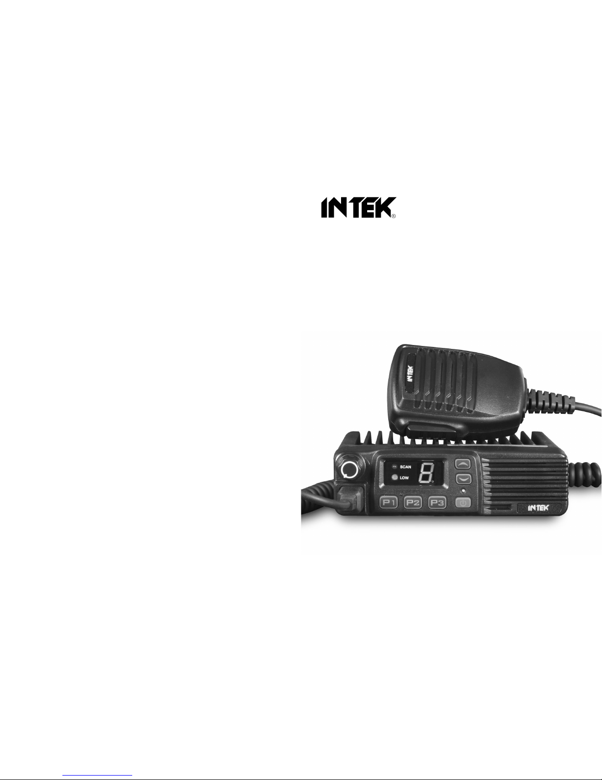
136-174 MHz VHF FM / 8CH / 5W-25W
PROFESSIONAL MOBILE RADIO
PC PROGRAMMABLE
MX-8000V
438-490 MHz UHF FM / 8CH / 5W-25W
PROFESSIONAL MOBILE RADIO
PC PROGRAMMABLE
MX-8000U
Page 2

INSTRUCTION MANUAL
MX-8000V / MX-8000U
VHF / UHF
PROFESSIONAL MOBILE RADIO
MANDATORY SAFETY INSTRUCTIONS TO
INSTALLERS AND USERS
Use Only manufacturer or dealer supplied antennas.
Antenna minimum safe distance: 108 cm.
Antennas used for this transmitter must not exceed
an antenna gain of 3 dBi.
Antenna mounting: The antenna supplied by the
manufacturer or radio dealer must not be mounted
at a location such that during radio transmission, any
person can come Closer than the above indicated
minimum safe distance to the antenna (i.e. 108cm).
16
Vehicleinstallation:Theantenna can be mounted at
the center of a vehicle metal roof or trunk lid if the
minimum safe distance is observed.
Antenna substitution: Don't substitute anyantenna
for the one supplied or recommended by the
manufacturer or radio dealer.Youmay be exposing
person(s) toexcessive radio frequency radiation. You
may contact your radio dealer or the manufacturer for
further instructions.
WARNING !
Maintain a separation distance from the antenna to
person(s) at least 108cm.
Page 3
.
NOTICE !
It is recommended to carefully read this owne r ’s manual before using the
product. This will also help the user to prevent using the radio in violation of
the regulations valid in the country where the product is used, as well as to
avoid any possible inte rferences with others ervices.
NOTICE !
This transceiver has been factory pre -programmed, in order for the user to
test it right after purchase . It is th e user ' s responsibilit y t o re - progra m
th e radio , in accordanc e wit h the specifications for the fre quency channels
assigned by the local authorit y.
NOTICE !
This transceiver is programmable via PC, using the dedicated software and
the PC interface cabl e (optiona l items) . An y programmin g o r modificatio n o f
th e origina l defaul t settin g mus t be made by a specialised technician or by
an authorised service centre. Some functions of this transceive r migh t b e
programme d in violatio n o f th e technica l rule s in forc e fo r th e us e o f th e VHF
an d UH F F M bands . I t is th e use r ’s responsibilit y t o chec k tha t an y
mod ificatio n t o the programming will be done in compliance with the
current regulations. Any modification to the product , alteratio n o f th e interna l
circuit , o f th e externa l structur e o f th e radi o o r an y programming in violatio n o f
th e curren t regulation s wil l automaticall y voi d th e produc t certificatio n an d you r
right to us e th e product . INTE K S.R.L . decline s an y responsibilit y concernin g
an y modificatio n o f the product , mad e b y th e use r o r b y a thir d part y, afte r deliver y
o f th e product.
CONTENTS
1. Package-openedInspectionand Installing.................................2
2. Radio Overview......................................................................... 4
3. Basic Operation......................................................................... 6
4. Programmable ButtonFunction................................................. 7
5. Radio call................................................................................... 8
6. Talk-around................................................................................ 9
7. Scan........................................................................................... 9
7.1 Start/End Scan Function........................................................... 9
7.2 Nuisance Delete........................................................................ 9
8. PublicAddress......................................................................... 10
9. Lone worker............................................................................. 10
10. EmergencyAlarm..................................................................... 10
11. Remote kill, stun, activate and revive..................................... 11
12. Wired Clone Mode....................................................................12
13. TroubleShootingGuide.......................................................12-13
14. Major Specifications.................................................................13
1
Page 4

Accessories
Quantity
Fixed bracket
1
Power Cable
1
Hand Microphone
1
Microphone Hanger
1
M4*10 Combination Screw
4
M4*16 Self-tapping Screw
2
M5*16 Self-tapping Screw
4
Instr
uction Manual
1
Protective tube
2
1. Package-opened Inspection and Installing
Please check the host in the package and the supplied accessories in
the following table before using. Any articles are found lost or
damaged,please contact the distributorwithout delay.
1.1 Supplied Accessories
Microphone
Hanger
protective
tube
M4x10
Combination
Screw
M5x16 / M4x16
Self-tapping
Screw
Power Cable
Hand Microphone Fixed bracket
2 3
1.2 Preparation
1.2.1Connection of Power Cable
First of all, please check whether there is a hole for the power
cable on the insulating board. If no, please bore the board with
the suitabledrill bit and fixa rubber grommet on it.
Afterwards, please have the cable pass through the insulating
board and lead from the car into the car engine. Connect the red
conductor tothepositive terminal of theaccumulator and the black
conductorto the negative terminal.
Atlast,ring the remainedconductor and fix it.
Note: Please maintain the sufficient relaxation of the power
cable to make it convenient to dismantle the radio in the
state ofpower connection.
1.2.2Radio Installing
Warning: For passengers' safety, please fix the radio firmly
on the fixed bracket so that the radio will not be loosened in
case of collision.
The fixed bracket is taken as an example. Draw the position
and drill a hole on the instrument panel first, and then install
the fixed bracket with 4 M5*16 self-tapping screws. (Note:
please fix the radio at the position convenient for
operation and control, and leave an enough space for
fixation and connection of the cable.)
Slide the radio into the fixed bracket and fix it with 4 M4*10
combination screws (plus plain washer and spring
washer).
(Different combinations of fixing holes are selectable to
adjust the radio to the proper height and visual angle.)
Page 5

Displa y
Descriptio n
SCAN indicator
Scan indication: on when scan is enabled .
LOW indicator
Power level indication: on when in low powe r.
Indicates the current channel in normal use,
ranging from 1~8.
Indicates the current squelch level when
squelch selection is enabled,ranging from
0.~9.
Displays "B" when Public Address is enabled.
Displays "-" when the radio has no channel.
Displays "U" when the radio is in the remote
stun status.
Displays "h" when the radio is in the remote
kill status.
Connect the antenna and the power cable to the radio.
Install the microphone hanger at the position easy to use, with
2 M4*16 self -tapping screws. (The microphone and its cable
should be fixed at the position not affecting safe driving.)
Connect the microphone to the microphone jack on the front
panel of the radio and put it on the hange r.
Note: W hen replacing the protective tube for the power cable,
please use the one of the sam e specification without fail. It is not
allowed to change it into the tube of higher capacit y.
7.
P1button (programm a ble button)
8.
P2 button (program mable button)
9.
P3button (programm able button)
10.
PTT button (on the hand microphone)
Press the PTT button first, and then speak to the m icrophone to transm it the
voice to the othe r. Loosen to receive.
2. 2 D ispla y S cr ee n
8
2 Radio Overview
2.1 Description of
External V iew
1.
power button
Press this button for
a long time (more than
1.5 seconds) to switch
The radio on/o ff.
2.
LED indicator
The red indicator will light while
transmit ting; the green indicator
Will light when it receives the carrie r.
3.
/ button (programmable button)
4.
Display screen
For details, see Display .
5.
Volume Control knob
To be used to adjust volume.
6.
Microphone/Programming Interface
4 5
Page 6

Display
Description
Displays "P" when the radio enters the PC
Programming Mode.
Displays "t" when the radio enters the PC
Adjustment Mode.
Displays "C" when the radio enters the Wired
Clone Mode
。
0. None
No function
1.Channel Up
Select thenext channel
2.Channel Down
Select theprevious channel
3.Talk-around
Switch the radio mode between talk-aroundand repeater.
4.Call Button1
Sends theDTMF/2Tonecode assigned to call 1 button.
5.Call Button2
Sends theDTMF/2Tonecode assigned to call 2 button.
6.Lone worker
Enables Lone worker function
7.Emergency
Alarm
Press the button programmed as“Emergency Alarm
”
to set alarm tone according to the programming software
or send yourown ID orbackground voiceto your partner
or thesystem.
8.Emergency
Alarm Off
Press thisbutton to quit the EmergencyAlarm mode.
9.Scan
Start/end the scanningfunction of system.
10.Nuisance Delete
Press thisbutton Nuisance Delete when the radio enables
11.Hi-Low Power
Switch
the scanfunction and staysat the noisechannel.
Pressto switch between high and lowpowerofthe sending
power of the radio, whenthe“LOW”ison the display,
in the normal voice. Please keep the microphone about 3 or 4 cm
far from yourmouth.After speaking, pleaseloosen the PTTbutton.
5. Receive:
The radio will return to the receiving state after you loosen the
PTT button. The distributor may have set the CTCSS/DCS
signaling in your radio. On the channels with CTCS S/DCS are
set, you can only hear the call from other radio with the same
CTCSS/DCS.
2.3 Rear Panel
1.
AntennaInterface
2.
PowerInterface
3.
ExternalSpeaker Interface
3 2 1
4. Programmable Button Function
P1, P2,P3 / can be programmed as one of the following
functions.
3. Basic Operation
1. Startup:
Press the red POWER button for a long time (at least 1.5
seconds) to switch the radio on/off
2. Volume:
Press the MONITOR or Squelch Off button to listen to the
background noise first, and then adjust the volume by turning the
volume control knob.
3. Channel
The radio can provide 8 general channels. Press the CHANNEL
UP or CHANNEL DOWN button to select the channel.(Refre to P7
4 Programmable Button Function)
4. Transmission:
To send a call, press the PTTbutton and speak to the microphone
6
7
Page 7

the currentsending power islow.
12.Monitor
Hold to disable C TCSS/DCS signaling according to the
momentary
setting to resume normal operation.
13.Monitor
Press to disable CTCSS/DCS signaling to receive signals
that cannot be heart in normal operation, press again to
resume normal operation.
14.Squelch o ff
Hold to enable squelch and loosen to resume normal
momentary
operation.
15.Squelch o ff
Press this button to open the squelch. Press it again
to return to the normal operation.
Press this button in the selective call state to quit such a state.
16.Lone worker
After enabling the Lone worke r, press this button to
reset
reset the Lone worker timer and the timing resumes.
Start/end the public address function. Pressthis button and
17
.Public
the functionwill be activated.PressthePTTbuttonand speak
Address
to themicro-phone so thatyou can hear your voice through
the externalspeaker.Press thisbutton once again and return
to thenormal user mode.
Press thisbutton to enterthe Squelch Level Adjustment
18.Squelch
Mode first,and then pressthe / button to adjust thelevel.
Level
Press thePTT button to save the selected squelch level and
Selection
quit thismode. Press any other button toquit without saving.
6. Talk-around
In the communication network, you can expand communication
range through the repeater, but when the mobile radio is out of the
communicationrange, you can connectwith other radio inthe
talk-aroundmethod.
Switch the talk-around or repeater mode through "Talk-around"
button.
7. Scan
The radiocan be programmedtoscan multiple channelsto receive
signals.
7.1 Start/EndScan Function
Press the button programmed for "Scan" to enable scanning.
When the scan function is enabled,the "SCAN" indicator is on and
the channels being scanned are also displayed. Press the "Scan"
button again to disable scanning and the"SCAN" indicator will be
out.
5. Radio call
A. Press the button programmed as "call Button 1" or "call Button 2"
tosendthe preset code .
B. Press "PTT" and talk with the microphone in the normal voice.
Please keep the microphone about 3-4cm away from your lips.
Whenfinishtalking, release "PTT".
7.2 NuisanceDelete
If a channel continuously generates noise or interference, press
the buttonto remove this channelfrom the scan listtemporarily.
Note: the priority channel can't be removed and the last one in the
scan list, either.Quitthe Scan mode and enter it again, the deleted
channel willbe added to thescan list again.
8 9
Page 8

8. Public Address
Press the button programmedfor "PublicAddress", "b" will be
displayed.Press the PTTbutton, the voice from the MIC of the
radio will be directly sent to the external speakers through the
interfaceonthe back.
Pressthe "Public Address"button again to disablethe public
softwareor send Yourown IDorbackground voice to yourpartner
or thesystem.
In the EmergencyAlarm Mode,pressthe button "Emergency Alarm
Off" to quit the Emergency Alarm Mode and disable the alarm tone
or stopsending it and resumenormal operation.
addressfunction.
9. Lone worker
If Lone worker is set to be enabled, press the button "Lone
worker" to enable the Lone Worker Mode. Start the Lone
worker timer and when the preset Lone worker time is
reached, the radio willalarm, afterthe alarmtime,the radio will
enter theEmergency Alarm Mode.
In the Lone worker Mode, press the "Lone worker" button
again toquitthe Lone workermode.
In the Lone worker Mode, press the button programmed for
"Lone worker reset" the specific button to select lone worker
reset mode or any button (any button to select lone worker
reset mode), the Lone worker timer will reset and start timing
again.
11. REMOTE KILL, stun activate and revive
Iftheradio received DTMFcode programmed as remotestun,
theradio willenter theremotestunstatus,afterreplying
according to the setting, "u" will be displayed. The radio can only
receive signals and cannot send signals. If the radio received
DTMPcode programmed asremoteun-stun, the radiowill quit
the remotestun status and enternormal operation.
If the radio received DTMF code programmed as remote kill, the
radio will enter the remote kill status, after replying according to
the setting,"h" will be displayed.Theradiocannotsendorreceive
signals. If the radio received DTMP code is programmed as
revive, the radio will quit the remote kill status and enter normal
operation.
12. Wired Clone Mode
Ifthewired clone functionis enabled, the radiowill not quit after
enteringthe wired clone mode.Toreturn to normaluser mode,
10. EmergencyAlarm
Press the button programmed for "Emergency Alarm" (the
time of pressing must be longer than the de-bounce time of
the emergency alarm switch) to enter the Emergency Alarm
mode. "E" will be displayed.Youcan set alarm tone according
totheprogramming
the userneeds to restartthemachine.
The operatingsteps go as follows:
1.Press[P1] buttons for power-onuntil show "C" andenterthe
10 11
Page 9

N
O.
Problem
Solution
B.Thehigh-frequencyamplifyingtubeQ18 isbroken.
Pleasechange it.
C.Thesquelch levelisset to highPleasereset the
squelchlevel.
D.Themixed tubeQ19isbroken. Pleasechangeit.
E.TheFM IC6 isbroken. Please changeIC.
5
The red transmission
Indicator lights but no
sound isheard.
A.Power moduleIC1damaged,no poweroutput,
pleasechange themodule.
B.MICdamaged, pleasechange it.
6
The green receiving
indicator lights but no
sound isheard.
A.Thespeaker is broken.Please changeit.
B.Theaudio poweramplifierIC7is broken. Please
changeIC.
NO.
Problem
Solution
1
Power on
Failure
A. Th e powe r cable is not connecte d with the accumulato r or the host
reliabl y. Please connect the power cable reliabl y.
B. The protective tube of power cable is burnt out. Please change it.
C. The power button is of poor contact. Please change the silica
gel button or PCB button.
D. The rechargeable b attery is out of powe r. Please recharge or
change a new one.
E. CPU is broken, Please change the IC.
2
Phaselock loop
unlocked
(Beeping)
A. Channel frequency beyond the range, reset channel data.
B. The crystal X1 of phase lock loop is broken. Please change it.
C. The oscillator tube is broken. Please change it.
D. The IC3 of phase lock loop is broken. Please change IC.
3
Notalkback
A. The frequency is not right. Please reselect the channel
of the same frequenc y.
B. The CTCSS/DCS code is not the same. Please reset it.
C. It is out of the effective communication range.
4
Noreceiving
signal
A. The antenna is not in good contact. Please fasten the antenna
head.
clone mode. If the function is disabled, it will enter the user
mode.
2. Connect the slave radio with the wired clone cable first, and
then turnon.
3. Press button [P2] on the master radio for starting clone. During
transmitting the data, the master radio lightens red, and the
slave radio lightens green and indicates "P". After the slave
radio receiving all the data, the red light on the master radio is
off,andtheslave radiorestarts.
4. You can keepcloning according tostep 3 above.
13. Trouble Shooting Guide
14. Major Specifications
FrequencyRange: 136MHz~174MHz (MX-8000V)
438MHz~490MHz (MX-8000U)
ChannelNumber: 8
ChannelSpacing: 25kHz(wide band)
12.5kHz(narrow band)
Operating Voltage: 13.6VDc±10%
OperatingTemperature: -25
°C /
-+55
°C
Dimension: 150 x 53 x 130 mm
Weight: 1030g
12
13
Page 10

Declaration of Conformity MX-8000V
With the present declaration, we certify that the following products :
INTEK MX-8000V
comply with all the technical regulations applicable to the above mentioned products
in accordance with the EC Directives 2006/95/EC, 2004/108/EC, 99/5/EC.
Type of product : VHF PMR Transceiver
Details of applied standards : EN 300 086 -1/-2 1, EN 301 489-1-5
EN 60950-1
Manufacturer : INTEK S.R.L.
Via G. Marconi, 16
20090 Segrate, Italy
Tel. 39-02-26950451 / Fax. 39-02-26952185
E-mail : intek.com@intek-com.it
Contact Reference : Armando Zanni
Tel. 39-02-26950451 / Fax. 39-02-26952185
E-mail : intek.com@intek-com.it
Segrate, 13/11/2009 dr. Vittorio Zanetti
(General Manager)
DECLARATION OF CONFORMITY
EC Certificate of Conformity
(to EC Directive 2006/95, 2004/108, 99/5)
RoHS
2002/95/EC
Declaration of Conformity MX-8000U
With the present declaration, we certify that the following products :
INTEK MX-8000U
comply with all the technical regulations applicable to the above mentioned products
in accordance with the EC Directives 2006/95/EC, 2004/108/EC, 99/5/EC.
Type of product : UHF PMR Transceiver
Details of applied standards : EN 300 086 -1/-2 1, EN 301 489-1-5
EN 60950-1
Manufacturer : INTEK S.R.L.
Via G. Marconi, 16
20090 Segrate, Italy
Tel. 39-02-26950451 / Fax. 39-02-26952185
E-mail : intek.com@intek-com.it
Contact Reference : Armando Zanni
Tel. 39-02-26950451 / Fax. 39-02-26952185
E-mail : intek.com@intek-com.it
Segrate, 13/11/2009 dr. Vittorio Zanetti
(General Manager)
DECLARATION OF CONFORMITY
EC Certificate of Conformity
(to EC Directive 2006/95, 2004/108, 99/5)
 Loading...