

Page 1
Multi-Parameter Monitor
Model MPM-1 Technical Manual
Page 2

Multi-Parameter Monitor
Model MPM-1
Technical Manual
1 Introduction
1.1 Disclaimer and Warnings......................................................................... 1-2
1.2 System Overview ..................................................................................... 1-4
1.3 Technical Specifications .......................................................................... 1-7
1.4 Limited Warranty................................................................................... 1-10
1.5 Contact Information ............................................................................... 1-11
2 Operation
2.1 General Operation.................................................................................... 2-2
2.2 Principles of Operation ............................................................................ 2-9
3 Testing and Preventive Maintenance
3.1 Operational Testing.................................................................................. 3-2
3.2 Battery Replacement.............................................................................. 3-26
3.3 Bedside Monitor Calibration.................................................................. 3-27
4 Troubleshooting
4.1 Introduction.............................................................................................. 4-2
4.2 Power Supply Malfunctions..................................................................... 4-3
4.3 LCD Malfunctions ................................................................................... 4-4
4.4 Error Messages......................................................................................... 4-5
4.5 Cabling and Interfacing Problems ........................................................... 4-7
5 Technical Notes
40201–C MPM-1 Technical Manual
Page 3

1 Introduction
1.1 Disclaimer and Warnings..................................................................................... 1-2
1.2 System Overview ................................................................................................. 1-4
1.3 Technical Specifications ...................................................................................... 1-7
1.4 Limited Warranty............................................................................................... 1-10
1.5 Contact Information ........................................................................................... 1-11
40201–C
1-1 MPM-1 Technical Manual
Page 4

1.1 Disclaimer and Warnings
PROPRIETARY INFORMATION
INFORMATION CONTAINED IN THIS TECHNICAL MANUAL IS
PROPRIETARY TO INTEGRA NEUROSCIENCES AND MAY BE USED
ONLY FOR THE PURPOSE OF PERFORMING OPERATIONAL CHECKS.
THE PURCHASE OR POSSESSION OF THIS MANUAL DOES NOT
CONFER, TRANSFER OR LICENSE ANY OTHER RIGHTS TO THIS
INFORMATION. ANY OTHER USE OR DISCLOSURE AND/OR
REPRODUCTION (BY ANY METHOD) OF THE INFORMATION
CONTAINED HEREIN IS STRICTLY PROHIBITED UNLESS WRITTEN
PERMISSION IS OBTAINED FROM INTEGRA NEUROSCIENCES.
AUTHORIZED SERVICE
This manual is intended for use by biomedical personnel to perform operational
checks. Any adjustments or procedures that exceed the scope of this manual
should be referred to Integra NeuroSciences.
Integra NeuroSciences does not condone or approve of service activity on its
products by anyone other than Integra NeuroSciences personnel; and Integra
NeuroSciences is not responsible for any unauthorized repairs.
DEFINITION OF DANGER, CAUTION AND NOTE
Danger – means there is the possibility of injury or death to you or others.
Caution – means there is the possibility of damage to the unit or other property.
Note – indicates points of particular interest for more efficient and convenient
operation.
SAFETY CONSIDERATIONS
Danger – Risk of explosion if used in the presence of flammable anesthetics.
Caution – Do not autoclave or immerse the MPM-1 as damage may occur. If the
MPM-1 is exposed to liquids, turn off the unit, remove the power cord
and thoroughly dry the unit before reapplying power.
Caution – Do not use solvents or cleaning agents as they could damage the plastic
exterior of the MPM-1.
Caution – To reduce the risk of electric shock do not remove the cover. Refer
servicing to qualified personnel.
Caution – Read Directions for Use before connecting to bedside patient monitors.
Caution – Grounding reliability can only be achieved when connected to Hospital
Grade Receptacle.
Caution – Where the integrity of the external PROTECTIVE EARTH
CONDUCTOR arrangement is in doubt, the equipment shall be
operated from its internal electrical power source (battery).
40201–C
1-2 MPM-1 Technical Manual
Page 5

Caution – This equipment should not be used with high frequency surgical
equipment.
Caution – Integra NeuroSciences Catheters are for single use only. Do not
attempt to re-sterilize or reuse. Integra NeuroSciences cannot assume
any responsibility for damage caused by re-sterilized Catheters. Used
catheters should be considered as a potential biohazard. Follow all
established laws and regulations pertaining to the handling and disposal
of biohazardous materials.
Caution – The MPM-1 contains Static Sensitive Devices. Observe proper ESD
precautions when working with Static Sensitive Devices.
SHIPPING INSTRUCTIONS
A shipping container is available. To insure proper preparation and shipping,
contact Integra NeuroSciences for instructions.
APPLICABILITY
This Technical Manual is applicable to the Multi-Parameter Monitor with
waveform display, Model MPM-1. Contact Integra NeuroSciences for
information for equipment not covered in this manual.
Integra NeuroSciences reserves the right to change specifications and procedures without
notice.
40201–C
1-3 MPM-1 Technical Manual
Page 6
1.2 System Overview
1
2
3 7
4 8
5 9
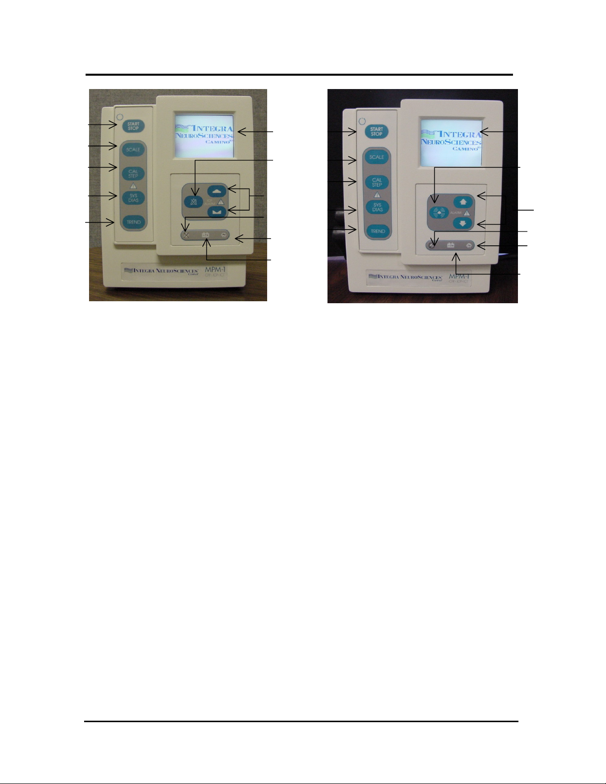
Figure 1-1 International Front Panel
1
6 6
7 2
3
4 8
5 9
10
11
Figure 1-2 Domestic Front Panel
1. START/STOP – Press to turn MPM-1 on or off.
2. SCALE – Press to change scale of pressure waveform on MPM-1 Display.
3. CAL STEP - Used to calibrate or check correlation of external bedside monitor.
4. SYS/DIAS – Press to toggle between the CPP-ICP-ICT display and the
SYSTOLIC-ICP-DIASTOLIC display.
5. TREND – Press to graphically display the last 12 or 24 hours of ICP and/or CPP
values.
6. LCD DISPLAY – Displays ICP waveform, numerical values and trend data.
7. SILENCE ALARM – Press to silence the alarm for 3 minutes.
8. UP and DOWN – Press the button(s) to set the desired alarm limit value.
9. ALARM DISABLED INDICATOR – Illuminates whenever the ICP alarm limit is
set to OFF. Flashes when alarm is temporarily silenced.
10. AC POWER INDICATOR - Illuminates when MPM-1 is connected to ~AC
power. The battery will charge whenever this indicator is illuminated.
11. LOW BATTERY INDICATOR – Illuminates when MPM-1 is operating on
Battery power and less than fifteen minutes battery life remains.
10
11
40201–C
1-4 MPM-1 Technical Manual
Page 7
12
13
14
15
16
17
19
18
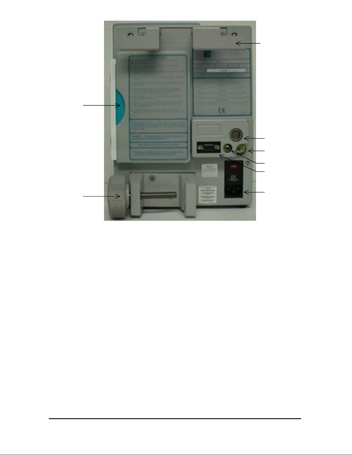
Figure 1-3 Rear Panel
12. COMBINATION CORD WRAP, HANDLE, and BED RAIL MOUNT
13. DFU POCKET – Storage location for the Directions for Use booklet.
14. BEDSIDE MONITOR CONNECTOR – Used for connection to the bedside
monitor.
15. EQUIPOTENTIAL CONNECTOR – Used as the connection point for
equipotential systems.
16. ICP ISOLATED ANALOG CONNECTOR – Used for data acquisition needs.
Provides 1V/100 mmHg output suitable for computer ADC’s or a strip chart
recorder.
17. RS232 CONNECTOR – Used for data acquisition needs. Please contact Integra
NeuroSciences for details on use of this digital data.
18. AC CONNECTOR – Attachment point for the ~AC power cord. Automatically
selects input ~AC voltage of 100, 115 or 230 Volts. Must be plugged into an AC
source whenever it is desired to maintain a charge on the internal battery.
19. POLE CLAMP – Used to secure the MPM-1 to an equipment pole.
40201–C
1-5 MPM-1 Technical Manual
Page 8
20a
20c
20b
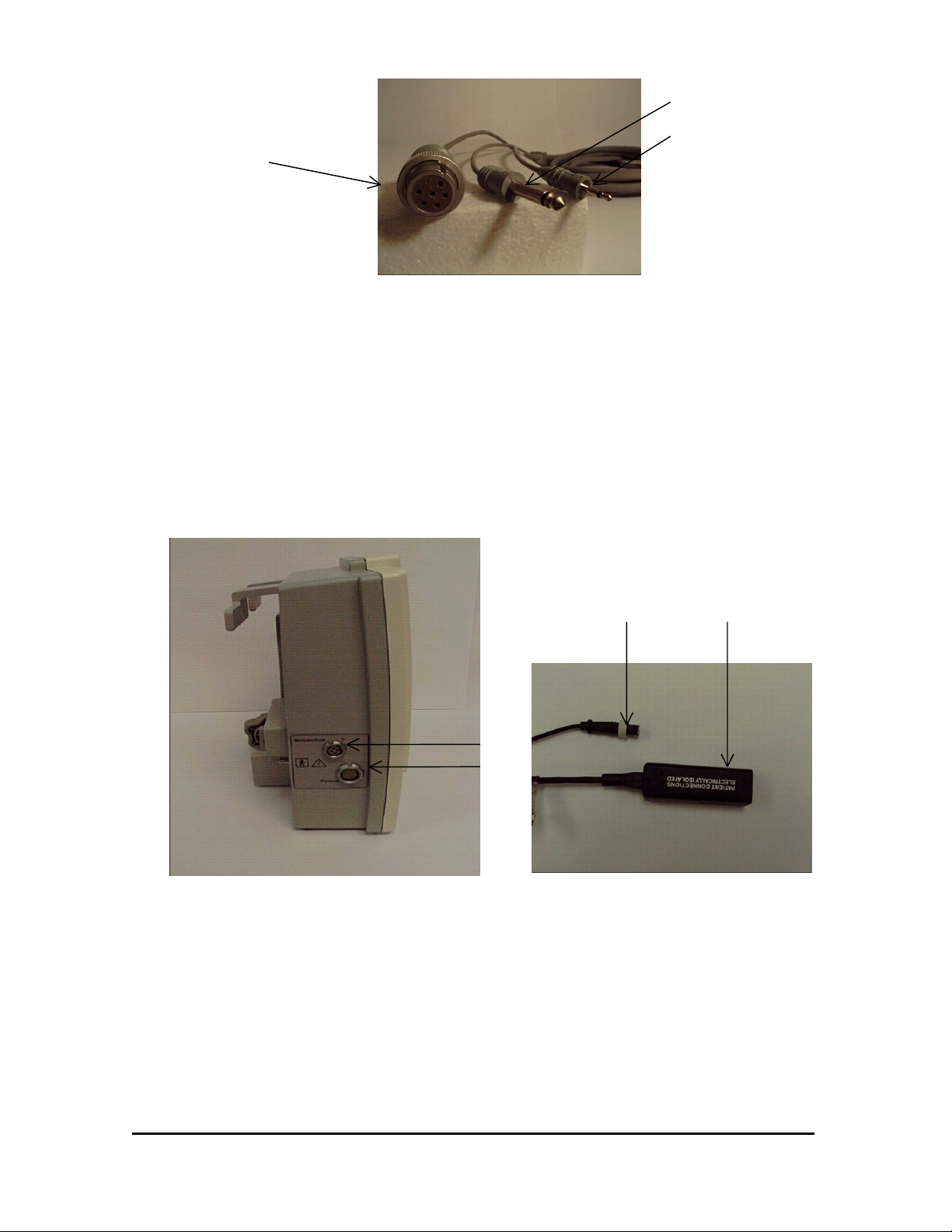
Figure 1-4 Bedside Monitor Cable
20. BEDSIDE MONITOR CONNECTOR – Used for connection to the bedside
monitor.
20a. ICT data to Bedside Monitor (Standard Phone Plug)
20b. ICP Waveform to Bedside Monitor (6-Pin Cannon Connector)
20c. Arterial Pressure Data to MPM-1 (Miniature Phone Plug)
22a 21a
22
21
Figure 1-5 ICP & ICT Connectors
Figure 1-6 Preamp Cable
21. ICP CONNECTION – Attachment point for the Preamp Cable Connector.
21.a ICP Catheter to Preamp connection.
22. TEMPERATURE CONNECTION – Attachment point for the Temperature Cable
Connector.
22.a ICT Catheter temperature connection.
40201–C
1-6 MPM-1 Technical Manual
Page 9

1.3 Technical Specifications
INTRACRANIAL PRESSURE (ICP)
Sensor Type: Fiber-optic pressure transducer
Range: -10 to +250 mmHg
Resolution: 1mmHg for LCD display
0.125 mmHg for Patient Monitoring Systems
Linearity: See individual catheter specifications.
Hysteresis: See individual catheter specifications.
Freq. Response: 120 Hz nominal, 100 Hz minimum (3dB down)
1.32 mSec for analog output
Accuracy: ± 1 mmHg
Reference Pressure: Atmospheric
INTRACRANIAL TEMPERATURE (ICT)
Sensor Type: Thermistor transducer
Display Range: 16.7°C to 42.2°C (65°F to 108°F)
Accuracy: ± 0.3°C (0.5°F) [30ºC - 40ºC]
MEAN CEREBRAL PERFUSION PRESSURE (CPP)
Type: Calculated
Range: 0 to 200 mmHg
Resolution: 1 mmHg
Accuracy: ± 1 mmHg
ALARMS
Audible: 2kHz ± 1kHz signal, ON 0.5 seconds and OFF 0.5 seconds
at full amplitude
High ICP Alarm: 0 to 250 mmHg, 1 mmHg increments
Low CPP Alarm: 0 to 150 mmHg, 1 mmHg increments
Alarm Silence: 3 minutes
40201–C
1-7 MPM-1 Technical Manual
Page 10

MONITOR INPUTS
“Trapezoidal” pre-amplifier input connection for Integra NeuroSciences ICP
catheters
Isolated 3-wire thermistor based TDC input for Integra NeuroSciences ICP/ICT
catheters.
Isolated Arterial Pressure (AP) for bed side patient monitoring systems. (1V/100
mmHg)
MONITOR OUTPUTS
Analog ICP for patient monitoring systems. (5µV/V/mmHg) (6-Pin CANNON
WK-6 connector)
Analog ICT for patient monitoring systems. (Standard 3-wire YSI 400 interface)
(Switchcraft ¼” Plug connector)
Analog ICP for data recording. (1V/100 mmHg) (Switchcraft Model 750
connector)
RS-232 Serial data port. Contact Integra NeuroSciences for details. (9 pin DB9
male connector)
DISPLAY
Type: Backlit TFT active matrix LCD panel
Parameters displayed: Pressure Waveform
CPP, ICP, ICT (Main Screen)
Systolic, ICP, Diastolic (Systolic/Diastolic Screen)
12 and 24 hour Trend Information (ICP and CPP)
BATTERY
Type: Rechargeable, sealed lead acid
Charge Time: 8-10 hours to full charge
Operation Time: 1-2 hour from full charge
POWER REQUIREMENTS
100-230 V, 50/60 Hz, 50 VA
MONITOR OPERATING LIMITS
Temperature: 15°C to 40°C (59°F to 104°F)
Pressure: 700 hPa to 1060 hPa (20.67 inHg to 31.30 inHg)
Humidity: 20% to 95% RH
40201–C
1-8 MPM-1 Technical Manual
Page 11

SHIPPING/STORAGE LIMITS
Temperature: 0°C to 50°C (32°F to 122°F)
Pressure: 500 hPa to 1060 hPa (14.76 inHg to 31.30 inHg)
Humidity: 20% RH to 95% RH non-condensing
PHYSICAL DIMENSIONS
Size: 274 mm H x 216 mm W x 89 mm D
(10.8” x 8.5” x 3.5”)
Weight: 4.4 kg (9.8 lbs.)
IEC-60601-1
Class of Equipment: Class 1
Protection Against Fluids: Ordinary
40201–C
1-9 MPM-1 Technical Manual
Page 12

1.4 Limited Warranty
INTEGRA NEUROSCIENCES warrants that each new INTEGRA NEUROSCIENCES
product is free from defects in material and workmanship under normal use and service
for a period of two (2) years (except as otherwise expressly provided as to accessory
items) from the date of delivery by INTEGRA NEUROSCIENCES to the first purchaser
but not beyond the “Expiration” date stated on any product labeling. Surgical
instruments are guaranteed to be free from defects in material and workmanship when
used normally for their intended purpose. Any covered product which is placed by
INTEGRA NEUROSCIENCES under a lease, rental or installment purchase agreement
and which requires repair service during the term of such placement agreement shall be
repaired in accordance with the terms of such agreement. If any such defect occurs
during the warranty period or term of such placement agreement, the purchaser should
communicate directly with the INTEGRA NEUROSCIENCES home office. If returned
to INTEGRA NEUROSCIENCES at its home office, repair or replacement will be
carried out at INTEGRA NEUROSCIENCES' sole discretion, at INTEGRA
NEUROSCIENCES' expense, subject to the terms of this warranty and applicable
agreements. The defective product should be returned promptly, properly packaged and
postage prepaid. Loss or damage in return shipment to INTEGRA NEUROSCIENCES
shall be at CUSTOMER’s risk.
IN NO EVENT SHALL INTEGRA NEUROSCIENCES BE LIABLE FOR ANY
INCIDENTAL, INDIRECT OR CONSEQUENTIAL DAMAGES IN CONNECTION
WITH THE ACQUISITION OR USE OF ANY INTEGRA NEUROSCIENCES
PRODUCT. Further, this warranty shall not apply to, and INTEGRA
NEUROSCIENCES shall not be responsible for, any loss arising in connection with the
purchase or use of any INTEGRA NEUROSCIENCES product which has be repaired by
anyone other than an authorized INTEGRA NEUROSCIENCES service representative or
altered in any way so as, in INTEGRA NEUROSCIENCES' judgment, to affect its
stability or reliability, or which has been subject to misuse, negligence or accident, or
which has been used otherwise than in accordance with the instructions furnished by
INTEGRA NEUROSCIENCES. This limited warranty is exclusive and in lieu of all
other warranties, express or implied, and of all other obligations or liabilities on
INTEGRA NEUROSCIENCES' part and INTEGRA NEUROSCIENCES neither
assumes nor authorizes any representative or other person to assume for it any other
liability in connection with INTEGRA NEUROSCIENCES products.
INTEGRA NEUROSCIENCES DISCLAIMS ALL OTHER WARRANTIES, EXPRESS
OR IMPLIED INCLUDING ANY IMPLIED WARRANTY OF MERCHANTABILITY
OR OF FITNESS FOR A PARTICULAR PURPOSE OR APPLICATION OR
WARRANTY OF QUALITY, OTHER THAN THOSE EXPRESSLY SET FORTH IN
THE PRODUCT LABELING, INCLUDING THE APPLICABLE USER
INFORMATION. The foregoing shall not relieve INTEGRA NEUROSCIENCES from
strict tort liability, if otherwise applicable under governing law, for damages for personal
injury caused by a product defect that made the product unreasonably dangerous at the
time it was sold or placed.
40201–C
1-10 MPM-1 Technical Manual
Page 13

1.5 Contact Information
Customer Service Department
Integra NeuroSciences
105 Morgan Lane
Plainsboro, New Jersey 08536
(800) 997-4868 (USA/Canada)
(609) 275-0500 (International)
(609) 275-5363 (FAX)
CE Mark obtained in 1998
Authorized Representative:
MedPass International Limited
Windsor House
Barnett Way, Barnwood
Gloucester GL4 3RT, United Kingdom
40201–C
1-11 MPM-1 Technical Manual
Page 14

2 Operation
2.1 General Operation................................................................................................ 2-2
2.2 Principles of Operation ........................................................................................ 2-9
2.2.1 The Camino Catheter...................................................................... 2-10
2.2.2 Board 1 – Digital Board ................................................................. 2-12
2.2.3 Board 2 – Analog Board................................................................. 2-13
2.2.4 Board 3 – Power Supply, AC Input................................................ 2-18
2.2.5 Board 4 – Power Supply, DC Output............................................. 2-19
40201–C
2-1 MPM-1 Technical Manual
Page 15
2.1 General Operation
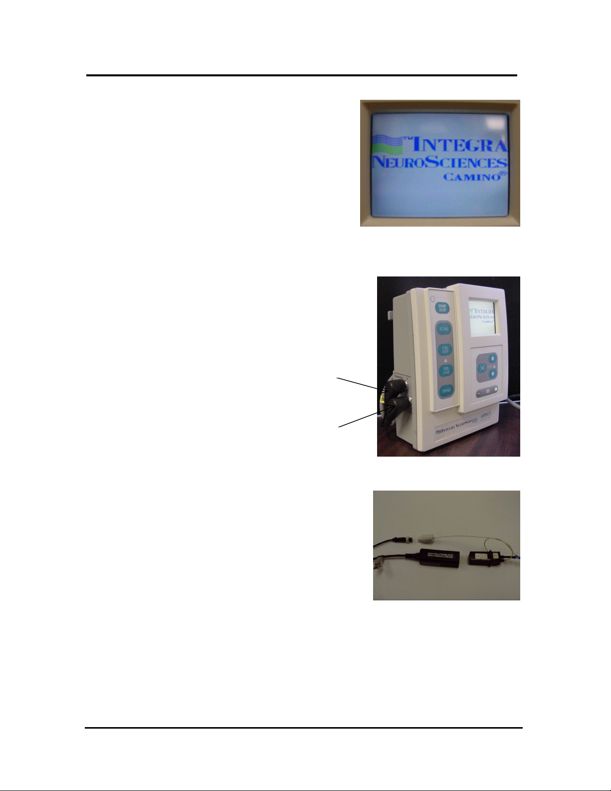
1. Turn on the MPM-1 by pressing the
START/STOP button on the front
panel. The MPM-1 will display the
“Camino Logo”(Figure 2-1).
2. Connect the Preamp Cable to the
MPM-1 by inserting the two cable
connectors in the appropriate
receptacle (Figure 2-2). Note the
red alignment marks on the cable
connectors and the side panel.
Temperature
Tran
sducer
Figure 2-1 Camino Logo
3. Select the desired Camino Pressure
Monitoring kit. Specific Directions
For Use may be found in the User
information insert provided with
each Pressure Monitoring Kit.
Pressure
Transducer
Figure 2-2 Preamp Cable to MPM-1
Figure 2-3 Catheter to Preamp Cable
40201–C
2-2 MPM-1 Technical Manual
Page 16
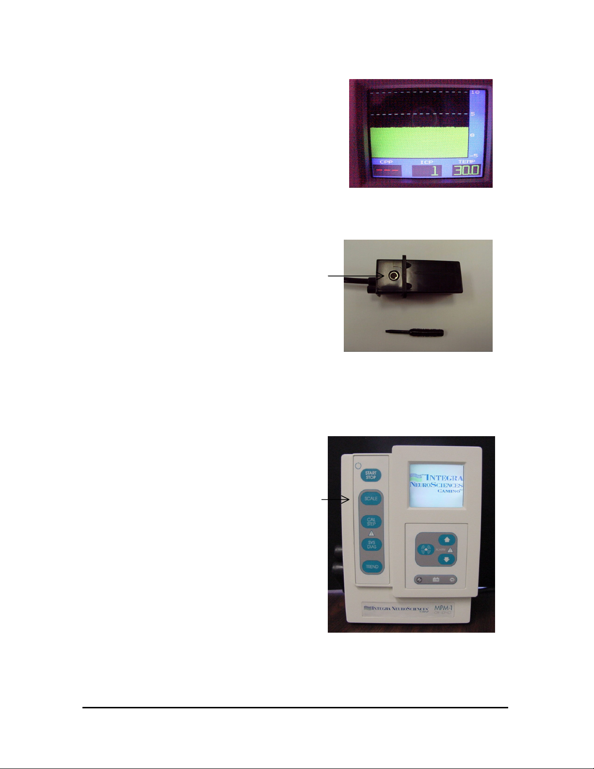
4. Remove the Catheter from the kit
tray, and firmly connect the
Transducer Connector(s) into the
Preamp Connector(s) (Figure 2-3).
(If a pressure only catheter is used,
then the temperature connector will
remain unconnected). After a short
system test, the MPM-1 Display
will change to the ICP/ICT display
(Figure 2-4).
5. Before inserting the Catheter into
the patient, ensure that the MPM-1
Display indicates an ICP Pressure
of “0 mmHg”. If not, use the tool
from the Catheter Kit to turn the
zero adjustment (Figure 2-5) on the
bottom side of the Transducer
Connector until the ICP Pressure
indicates “0 mmHg”. Also, ensure
that the temperature is a reasonable
value, such as room temperature,
before insertion of the Catheter into
the patient.
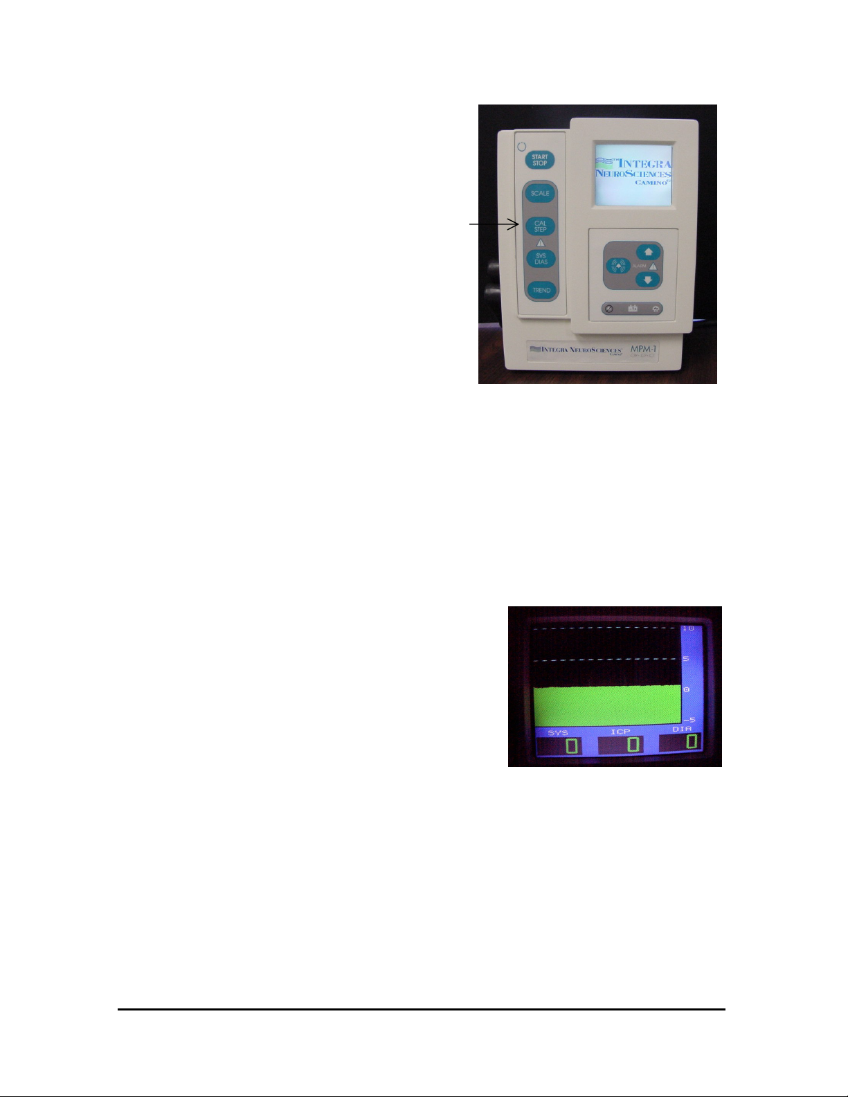
6. After the Catheter has been inserted
into the patient, (see the catheter
Directions For Use for proper
insertion technique) select the
appropriate scale by repeatedly
pressing the SCALE button on the
MPM-1 front panel (Figure 2-6).
Figure 2-4 CPP/ICP/ICT Display
Zero
Adjustment
Figure 2-5 ICP Catheter Transducer
Scale
Button
40201–C
Figure 2-6 Scale Button
2-3 MPM-1 Technical Manual
Page 17
7. If the MPM-1 is connected to an
external bedside monitor, the
CAL STEP button (Figure 2-7)
may be used to calibrate or
balance the bedside monitor. Each
press advances to the next mmHg
value in the following series: 0,
20, 40, 100, 200 and back to 0.
The CAL STEP momentarily
interrupts normal pressure signal
on both the MPM-1 and on the
external bedside monitor. Press
the CAL STEP button repeatedly
until 0 mmHg is displayed on the
MPM-1. While keeping the button
depressed to maintain 0,
simultaneously zero the bedside
monitor, then release the CAL
STEP button. Within a few
seconds, the MPM-1 will return to
the pressure display. Note that the
CAL STEP button may be used at
any time, and does not affect the
transducer calibration.
8. Press the SYS/DIAS button to
toggle between CPP, ICP, ICT
and SYS, ICP, DIAS displays
(Figure 2-8).
Cal Step
Button
Figure 2-7 CAL STEP Button
40201–C
Figure 2-8 SYS/DIAS Display
2-4 MPM-1 Technical Manual
Page 18
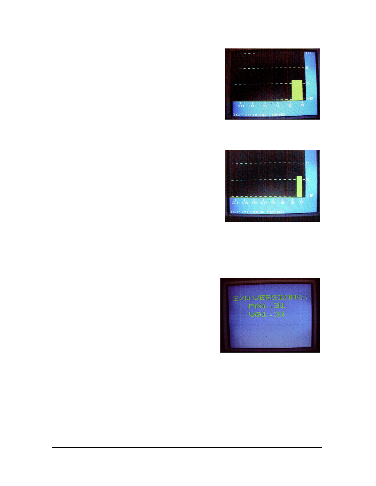
9. Press the TREND button to
display the mean ICP and CPP
value recorded during the
preceding 12 hours (Figure 2-9).
With the next press of the trend
button, the mean ICP and CPP for
the preceding 24 hours will be
displayed (Figure 2-10). Press
again to return to the pressure
display. To clear trend, turn
MPM-1 off momentarily.
NOTE - The trend information will
be lost if the MPM-1 is turned off
or if the battery discharges
completely and the MPM-1 turns
itself off.
NOTE - ICT and CPP values will
ONLY be displayed when using the
appropriate Catheter and/or bedside
monitor input connections.
NOTE - When not in use, the
MPM-1 must be connected to ∼AC
power to maintain battery charge.
TO DISPLAY THE MPM-1
SOFTWARE VERSION
• Make sure that the MPM-1 is
powered off.
• Connect the Pre-Amp cable.
• Insert a catheter to Pre-Amp cable.
• Press and hold the DOWN button.
• While keeping the DOWN button
depressed, power on the MPM-1
by pressing the START/STOP
button.
• Hold the DOWN button until the
SOFTWARE VERSION appears
on the screen (Figure 2-11).
• Wait approximately 5 seconds for
the graph screen to appear.
Figure 2-9 12 Hour Trend
Figure 2-10 24 Hour Trend
Figure 2-11- Software Version Display
40201–C
2-5 MPM-1 Technical Manual
Page 19
TO CHANGE THE GRAPH MODE
This feature is available on software
version 1.29 and later.
• The graph mode can be either LINE
or FILL (Figure 2-12).
• The initial default graph mode is
FILL.
• The graph mode is saved every time
Directions:
• Make sure the MPM-1 is powered
off.
• Press and hold the SYS/DIAS
button depressed, power on the
MPM-1 by pressing the
START/STOP button.
• Hold the SYS/DIAS button until the
graph screen appears.
• Repeat the above to revert to the
FILL Graph Mode.
TO SET HIGH ICP ALARM
• The initial default ICP ALARM is
set to OFF. After that, the level is
saved every time it is set.
• Reminder: The alarm sounds and
the ICP parameter blinks when ICP
goes higher than the set point.
Directions:
• While the MPM-1 is on, press the
UP or DOWN button, view the
Alarm Select Screen.
• Press the UP button to select the
High ICP ALARM (Figure 2-13).
• Press the UP or DOWN button to
set the ICP ALARM to the desired
level.
• Wait approximately 5 seconds for
ICP ALARM to be set.
• Pressing the DOWN button until
the word “OFF” appears disables
this alarm (Figure 2-14).
Figure 2-12 Line Graph Mode Display
Figure 2-13 High ICP Alarm
Figure 2-14 High ICP Alarm, OFF Mode
40201–C
2-6 MPM-1 Technical Manual
Page 20

TO SET LOW CPP ALARM
This feature is available on software
version 1.31 and later.
• The initial default CPP ALARM
level is OFF. After that, the CPP
ALARM level is saved every time
it is set.
• Reminder: The alarm sounds and
the CPP parameter blinks when
CPP goes lower than the set point.
Directions:
• While the MPM-1 is on. Press the
UP or DOWN button, view the
Alarm Select Screen.
• Press the DOWN button to select
the Low CPP ALARM (Figure 2-
15).
• Press the UP or DOWN button to
set the CPP ALARM to the desired
level.
• Wait approximately 5 seconds for
CPP ALARM to be set.
• Pressing the DOWN button until
the word “OFF” appears disables
this alarm (Figure 2-16).
Figure 2-15 Low CPP Alarm
Figure 2-16 Low CPP Alarm, OFF Mode
40201–C
2-7 MPM-1 Technical Manual
Page 21

TO SILENCE THE ALARM
• The initial default CPP ALARM
and ICP ALARM levels are OFF.
After that, the CPP ALARM and
ICP ALARM levels are saved in
memory every time they are set.
Directions:
• Press the SILENCE ALARM
button. The ALARM DISABLED
INDICATOR will flash and
whichever parameter, ICP or CPP,
was in alarm mode will now be
silenced for 3 minutes and that
parameter will flash on the screen
(Figure 2-17).
NOTE: The parameter that is in alarm
mode will blink (even if it has been
silenced). If both alarms were in alarm
mode when the SILENCE ALARM
button was pressed, both alarms will be
silenced. If one parameter (ICP or CPP)
has been silenced and the other
parameter goes into its alarm mode
during the 3 minute silence period, the
silence alarm mode is disabled (the
alarm sounds).
BOTH ALARMS OFF
• As a warning, the ALARM
DISABLED INDICATOR will be
ON (and the alarms will be
disabled) when both of the alarms
have been set to OFF.
Silence
Alarm
Button
Alarm
Disabled
Indicator
Figure 2-17 Alarm Button & Indicator
40201–C
2-8 MPM-1 Technical Manual
Page 22

2.2 Principles of Operation
The Integra NeuroSciences Multi-Parameter Monitor with Waveform Display (MPM-1)
is a compact, portable device for use with Integra NeuroSciences 110-4 series of
Pressure/Temperature and Pressure Transducer-Tipped Catheters. Pressure and/or
Temperature are measured at the Catheter tip, eliminating the need for external
transducers, fluid, pressure tubing, and flush devices. The MPM-1 displays Intracranial
Pressure (ICP), Intracranial Temperature (ICT), and calculates Cerebral Perfusion
Pressure (CPP)
Note – CPP = MEAN ARTERIAL PRESSURE – MEAN INTRACRANIAL
PRESSURE
The MPM-1 provides a continuous display of the ICP waveforms, as well as mean ICP,
CPP and ICT, or mean ICP, systolic and diastolic values. A continuous record of ICP and
CPP values over the most recent 24-hour period is stored in memory, and can be
displayed on command as a TREND, either as the most recent 12 or 24-hour period.
Although the MPM-1 is intended to be a stand-alone system, it also conveniently
connects to hospital bedside monitoring systems. Outputs for ICP and ICT are available
for use with patient bedside monitors. An isolated analog output provides a continuous
ICP waveform for hard copy documentation or data acquisition. An input to receive
Mean Arterial Pressure from a compatible patient bedside monitor is available for use
when it is desired to have a CPP reading.
A built-in rechargeable battery permits monitoring during patient transport.
Internally, the MPM-1 consists of four printed circuit board assemblies:
Board 1 – Digital Board
Board 2 – Analog Board
Board 3 – Power Supply, AC Input
Board 4 – Power Supply, DC Output
40201–C
2-9 MPM-1 Technical Manual
Page 23

2.2.1 The Camino Catheter
Intracranial Pressure (ICP)
A fiber optic device, that consists of four fibers, measures intracranial pressure. Light
from an LED source is transmitted down one fiber, called the sender. The light is
reflected off the polished surface of a mechanical bellows and is collected by another
fiber, called the receiver. The reflected light, referred to as SIGNAL, is collected by a
photo-detector.
The other pair of fibers have the same characteristics and length. They are mounted
similarly and exposed to the same light source but the light is not reflected off the
polished bellows surface. Instead, the light is looped around from the sender, back to the
receiver. The light received from this dummy path, termed REFERENCE, is compared
to the light received from the SIGNAL path, forming a ratio. If light from the LED is
increased or decreased, both paths are affected, thus for a given pressure, the ratio of the
two paths does not change.
REFERENCE JUNCTION
BELLOWS
SEND/RECEIVE FIBERS
40201–C
2-10 MPM-1 Technical Manual
Page 24

The transducer has a close to linear response for the pressure range of –20 to 300 mmHg.
However, the catheter response must be linearized in order to get the required resolution
from the transducer. This is accomplished by applying a known pressure to the catheter
during manufacture and recording the resultant output pressure. This pressure is used to
construct a lookup table that the microprocessor in the MPM uses to correct the pressure.
This process is called linearization correction.
Due to manufacturing variations, the ratio of the amount of reflected light from the
bellows displacement to the reference is not the same for all transducers. In order to
normalize the output of each transducer, the transducer response is rescaled so that the
output to displacement ratio is the same for all transducers. This process is a slope
correction.
When linearization and slope corrections are accomplished, CHARACTERIZATION of
the transducer is complete. These corrections are encoded in resistor values that are
measured by the instrument. These values are translated into correction factors that are
then applied to the SIGNAL and REFERENCE outputs of the transducer.
Intracranial Temperature (ICT)
Intracranial temperature (ICT) is measured by an electrically isolated thermodilution style
thermistor, placed directly behind the bellows region of the catheter. The thermodilution
thermistor is a cardiac industry standard for temperature measurement, and the variation
is quite linear over the region of 30 – 40 °C (normal body temperature is 37 °C).
40201–C
2-11 MPM-1 Technical Manual
Page 25

2.2.2 Board 1 – Digital Board
Board 1 performs the Digital functions of the MPM-1.
The digital section of the MPM-1 consists of two Zilog Z180 processors with their PSD,
SRAM and Flash RAM arranged in twin kernel configurations. The Programmable
System Device (Wafer Scale Integration, PSD412) provides 64K EPROM and 2K
SRAM, memory and I/O space decoding, as well as certain logic functions (glue logic).
Also there is an external 32K SRAM for other temporary scratchpad and memory
functions. These processor systems are linked together with a 12 bit parallel port to
transfer data. The basic functions of these processor systems are as follows:
Pressure Processor System (consisting of Z180 U5, PSD U4 and SRAM U34):
• establishes communication with the catheter, reading the code resistors, then writes to
the DACs on the Analog Board the corresponding values for that catheter.
• guards that the Reference Loop is maintained (catheter is not disconnected, nor
inoperational).
• receives intracranial pressure, arterial pressure, intracranial temperature and
membrane switch status data via its serial link from Board 2.
• transmits data via the same serial link to the ICT Output, PMIO and Isolated Analog
port
• linearizes (straightens) intracranial pressure data received with an algorithm based on
information received from the catheter Curve 1, 2 code resistors.
• communicates the received (modified) pressure data, with handshake, to the Video
processor.
Video Processor System (consisting Z180 U24, PSD U25, Flash RAM U19, Dual Port
RAM U21 and FPGA 8282 U26):
• interrogates most of the membrane switch inputs and takes appropriate action
• performs averaging of all data received and making it available for placement onto
the LCD.
• computes CPP with Arterial Pressure data and ICP data.
• writes data to all stationary locations on the LCD screen such as mean ICP, CPP, etc.
• writes the first vertical line of pressure data received, then waits for a NTSC screen
interrupt to write again, thus constantly refreshing the screen. As averaged data
becomes available, this entire screen is written one vertical pixel line to the right and
a new vertical line of pressure data is inserted to the left—this creates the animated
display image.
Isolated Power Supply (consisting of U23, T2-T4, Q2):
• A current-mode, flyback topology switching regulator with isolation transformers
provide isolated power for all electrical functions requiring low leakage and isolation
from potential electrical faults.
40201–C
2-12 MPM-1 Technical Manual
Page 26

2.2.3 Board 2 – Analog Board
Board 2 performs the Analog functions of the MPM-1.
Pressure
The pulsed output (representing raw Pressure) received from the PAC-1 preamplifier is
conditioned by a scaling circuit with a ZERO DAC (digital-to-analog converter), then
filtered to DC, and scaled with a SPAN DAC. This results in a 0 to 200mV output as
pressure varies from 0 to 250 mmHg. Any catheter manufactured by Integra
NeuroSciences is first characterized (the DAC levels are determined). When this
particular catheter is used in any MPM-1 monitor, the DAC settings are reproduced by its
analog pressure circuitry. Thus each catheter is “normalized,” producing a consistent and
accurate pressure output. This analog signal must now be routed to an ADC (analog-todigital converter) which converts the analog level to a digital representation that can be
used by the microprocessor. In order to adequately use the ADC with its 4 volts of input
range, another scaling circuit follows this 0 to 200mV circuit to produce 1.172 to 3.125
volts, respectively. This optimally fits the ADC range allowing the ADC to output 1200
to 3200 counts, respectively. This 2000 count span from 0 to 250 mmHg is a sensitivity
of 8 counts per mmHg (approximately 8 mV per mmHg).
Reference
The output of the Reference signal is essentially a mirror image of the Pressure signal
discussed above. Its purpose is to faithfully produce an output that contains no pressure
signal but otherwise emulates the Pressure signal path. The Reference signal is employed
in a servo balancing scheme to carefully control the LED light output to minimize
semiconductor temperature coefficients and other error producing variables.
LED Drive
The LED (located in the catheter) is pulsed by the LED Drive at an approximately 1.3
kHz rate, with an ON time that is 1/16 of the OFF time, i.e., it is ON for about 83
microseconds and OFF for 1.25 milliseconds. This allows for a chopper amplifier style
sampling of signals at a higher frequency followed by low-pass filtering and the
implementation of a unique method of subtracting dark currents and unwanted signals.
The end result is a drift-free system that produces an output with a large signal-to-noise
ratio.
Code Resistor Circuit
A 245 microampere current source is connected to each of 9 precision resistors one at a
time, and the subsequent voltage (Ohms Law, Vout = Current x Resistance) is read by the
ADC which enables the microprocessor to adjust DACs and certain parameters. As it
was discussed in the Pressure
duplicate the DACs of the manufacturing characterizing equipment. These code resistors
contain the information needed to setup the DACs and the software curve-fitting
algorithm coefficients.
description, the DACs are adjusted for any MPM-1 to
40201–C
2-13 MPM-1 Technical Manual
Page 27

ZAD Circuit
A 4 milliampere current source is connected to the ZERO potentiometer located in the
catheter. Prior to placement of the catheter into the patient the nurse adjusts this
potentiometer to achieve ZERO. This is a necessary system adjustment that allows
catheters and monitors with normal variations to come together and operate correctly.
ICT Signal Connection
The analog signal from the IntraCranial Temperature measurement circuit is routed to the
ADC for measurement and subsequent readout on the LCD display.
Arterial Pressure Signal Connection
The analog signal from the external Arterial Pressure circuit is routed to the ADC for
calculation of CPP (CPP = AP, mean – ICP, mean).
Reference Voltages
The +7 volt supply from Board 1 is used to produce a precision +4 volt supply needed for
the ADC reference and a –2 volt supply needed for Pressure offset bias and Reference
servo command.
PMIO
The Patient Monitor Input/Output (PMIO) connects the MPM-1 to the bedside monitor.
The bedside monitor “views” the MPM-1 as an external transducer. In the bedside
monitor industry the typical input is from a transducer arranged as a Wheatstone Bridge
which can be imagined as 4 resistors of equal value connected in a diamond shape. The
top two resistors are connected to the excitation voltage provided by the bedside monitor
and the lower two resistors are connected to the bedside monitor common. The center
connections, by virtue of equal resistance value and by voltage dividing action produce
an output of zero volts
. By replacing one of the lower resistors with a strain gage of
equal resistance, an output, linear to changes in the strain gage resistance with pressure, is
obtained. By changing the excitation voltage higher or lower, a corresponding higher or
lower gain of the signal is achieved. With this arrangement, the output is automatically
positioned at the origin (no offset) and gain is a linear function of the excitation voltage.
In the case of the MPM-1, the PMIO circuitry emulates
an external transducer. Isooptical couplers enable the linearized pressure signal from the microprocessor to be
output digitally, with isolation
. This digital signal is converted by the DAC to an analog
signal, then appropriately scaled by the excitation signal (with an offset that moves with
gain), and is split from single-ended into a differential output. The desired result is to
have proportionate gain by increasing the excitation signal without increasing the relative
offset provided by the pressure. The output can be described as follows:
counts
.
...
V
out
5106V
exc
512
4096
150
This equation implements the medical specification for transducers used with bedside
monitors--5µV/Vexc/mmHg, that is, 5µV output per 1 volt of excitation for 1 mmHg,
except it additionally describes the pressure/ADC count scale used by the MPM-1.
40201–C
2-14 MPM-1 Technical Manual
Page 28

Solving for 0 mmHg which would be Vout = 0 volts, the counts must be equal to
150*4096/512 = 1200 counts. Similarly, at the rate of 8 counts per mmHg, 2000 counts
would be added to 1200 counts for a total of 3200 counts which reduces the amount in
the parenthesis to 250, thus 250 would be taken times 5µV times the Vexc voltage used.
As an example, for 5 volts excitation voltage and 200 mmHg of pressure, the differential
output would be 5 mV. Note that at the special point of 1200 counts (0 mmHg), the
output remains at zero regardless of excitation voltage therefore this circuit satisfies the
above desired result of proportionate gain without undue influence from the normal
offset.
Isolated Analog Output
The Isolated Analog Output provides an isolated, analog output to a printer, or to a
computer ADC that is a function of linearized pressure from the microprocessor, centered
at the origin (no offset), at 1V/100 mmHg. The purpose of isolation is to insure that a
“dirty” printer or computer connection would not cause harm to the patient. The output is
0 volts for 0 mmHg and 2.5 volts for 250 mmHg. This pressure signal processor is
output digitally to the Iso Analog ADC, which is followed by an offset and gain signal
conditioning circuit. Finally, a special IC provides galvanic isolation, which performs the
same function as in the PMIO above.
Arterial Pressure
The Arterial Pressure circuit interfaces the bedside monitor with the MPM-1 providing an
arterial pressure value (in volts) needed for CPP calculations. The microprocessor
computes:
CPP = AP, mean – ICP, mean
This circuit provides high impedance buffering in order to not load the bedside monitor
arterial pressure output. Additionally, it provides a low- pass filtered output to the MPM1 ADC using a 2-pole active Butterworth filter with a cutoff frequency of 10 Hz. Since
the bedside monitor is unknown and may be electrically “dirty”, an IC that provides
isolation is used to preclude any current carrying paths to the patient. A simple low-pass
pole at 159 Hz follows this isolation circuit to eliminate bucket-charge noise spikes.
40201–C
2-15 MPM-1 Technical Manual
Page 29

Additionally, this circuit provides voltage translation from the bedside monitor to the
MPM-1. The electrical descriptions are:
Output of the Bedside Monitor
:
1V/100 mmHg with its output centered at the origin for zero arterial pressure or,
y
= 0.01 x1
1
where y
is the output in volts and x1 is the arterial pressure in mmHg
1
measured by the bedside monitor from an external source
Input of the MPM-1 Arterial Pressure Circuit
x
= 128 y1 – 150 (or y1 = 0.007812 x2 + 1.172)
2
where y
is the input in volts and x2 is AP in mmHg used by the
1
:
microprocessor in CPP calculations
ICT Input
• The ICT Input circuit receives a voltage from a thermistor located in the tip of the
temperature/pressure catheter and provides appropriate offset and gain for accurate
temperature measurement.
• The thermistor is a custom device built/tested with a “pad” resistor enabling the
thermistor manufacturer to state a narrow range of resistances over the range of 30°40° C. The linear ICT input circuit is calibrated at these two points during Final Test
of the monitor to minimize error, which, in turn, allows the MPM-1 specification to
be ± 3.0°C over this range.
• The thermistor has a characteristic that an increasing temperature causes its resistance
decrease
to
. The thermistor (placed on top) and pad resistor (placed on bottom) are
connected in series forming a voltage divider where the voltage at the center point
with respect to common
increases
with an increase in temperature.
• When +1.0000 volt is applied as an excitation voltage, the above center point output
varies from .3498 volts to .4376 volts for a temperature of 30° to 40° C, respectively.
This excitation level, which would cause thermistor self-heating errors in air, was
chosen because the application is, in fact, in fluid. Using this level produces a signal
output much higher than noise or thermocouple errors.
• This thermistor output is defined as:
40201–C
y (in volts) = .0048779 x (in °F) - 0.0696849 {°F }
y (in volts) = .0087802 x (in °C) + .0864079 {°C }
2-16 MPM-1 Technical Manual
Page 30

• In order to optimize the +4.0 volt ADC input range, the extreme displayed
temperatures of 59 °F (15°C) to 113 °F (45°C) were chosen to have 0 to 3.78 volts,
respectively. This essentially provides a 70 mV (126 mV) change for each degree °F
(°C) displayed. This uses the entire ADC range and enables the use of a convenient
software lookup constant.
• To provide an extremely stable and precise output with negligible input loading an
instrumentation amplifier was used. Calibration during manufacturing is also easier
with the unity/full gain feature of an instrumentation amplifier.
• Because the thermistor is patient connected, an IC that provides isolation is used to
preclude any current carrying paths to the patient.
• This ICT Input circuit output is defined as:
y (in volts) = .070 x (in °F) – 4.13 {°F }
y (in volts) = .126 x (in °C) – 1.89 {°C }
ICT Output
• The ICT Output circuit interfaces the MPM-1 to the bedside monitor providing a
continuous set of resistance values for temperatures from 15° to 45° C. This emulates
a standard 3-wire YSI 400 thermistor resistance. In essence, the bedside monitor is
performing a thermistor meter function of type YSI 400 with digital readout on its
screen and the MPM-1 is producing a varying resistance output as a function of
patient temperature in similar fashion to a true YSI 400 thermistor. This approach
was used because theYSI 400 series thermistor input plug-in module is a bedside
monitor standard.
• This unusual configuration was necessary in order to maintain isolation between the
MPM-1 and the bedside monitor, yet allow a temperature readout on the MPM-1
LCD display
and
the bedside monitor (in some cases the bedside monitor may be
remotely located).
• Since this circuit connects an unknown bedside monitor that may be electrically
“dirty” to the MPM-1, the ICT Output circuitry is isolated by virtue of ISO-optical
couplers and an isolated power supply.
• The ICT Output circuitry consists of a processor controlled serial-to-parallel
converter followed by latches that control eight solid-state switches, each connected
to its precision resistor which is connected in parallel with a fixed 3500 ohm resistor.
The switches are arranged in a kind of ladder form allowing binary closing. The
switches are
normally open
, thus there is approximately 3500 ohms presented to the
output terminals for the lowest temperature readout of 15° C. As the measured
temperature increases, successive switches are closed in a
binary fashion creating 256
unique states of resistance values. The resistance is thereby reduced for increasing
temperatures. The selection of the precision resistance values is a one-time effort
requiring the use of a curve-fitting computer program.
• Due to the inherent internal resistance of the solid-state switches, several gangs of
switches are used in parallel (to reduce series switch resistance and minimize system
error) for the last two rungs of the ladder where the output resistance is rapidly
approaching that of the solid-state switch internal resistance.
40201–C
2-17 MPM-1 Technical Manual
Page 31

2.2.4 Board 3 – Power Supply, AC Input
The AC Input Board of the Power Supply provides "Off-line" conversion from the
MAINS (AC Line) to +16.5 volts of isolated, regulated power for Board 4.
Input requirements:
• 90 VAC (low-line Japan) to 264 VAC (high-line Europe).
Output drives 3 separate loads:
• The monitor circuitry (when the monitor when ON).
• A dummy load which minimally loads this supply (when the monitor is OFF).
• The battery charging circuit.
Features:
• Power is taken directly from the LINE, hence the term “Off-line” converter.
• Fixed frequency, current mode pulse width modulator topology.
• Isolation from the LINE exceeds 4500 VAC for safety.
• Output noise is in ‘sync’ with the master clock to minimize beat frequency noise.
• Output level is controlled by an isolated optocoupler with bandgap reference.
40201–C
2-18 MPM-1 Technical Manual
Page 32

2.2.5 Board 4 – Power Supply, DC Output
The DC Output Board of the Power Supply provides DC-DC conversion from the source
to +5V for Logic and LCD, +15V for LED Drive, +9V and -8V for OpAmps. This
power is extracted from either of two sources, the 16.5 volts from Board 3 or the nominal
12 volts from the lead acid battery.
Input requirements:
• 16.5 volts from Board 3 (if AC power is available and connected).
• 12 volts, nominal, from the battery (10.8 volts, minimum).
Outputs:
• +5 volts for Logic and LCD.
• +15 volts for LED drive.
• +9 volts for Operational Amplifiers.
• -8 volts for Operational Amplifiers.
Features:
• AC LED is illuminated when AC power is connected.
• BATTERY LOW lamp is illuminated (whenever the unit is ON and using battery
power) and the battery is discharged to less than 11.8 volts, warning that the battery
charge is depleted.
• Long shelf life for fully charged battery (less than 10 uA leakage current).
• 5 volt output controlled by bandgap reference; other outputs track this output given
nominal loading.
• Output noise is in ‘sync’ with master clock to minimize beat frequency noise
• Shutdown of Board 4 supply automatically occurs when the battery is discharged to
less than 10.8 volts.
• Battery charging is current limited to about 330mA protecting both the battery and
preventing overheating of the voltage regulator.
• Battery charging is maintained at two different, constant-voltage levels, nominally
14.4 volts and 13.8 volts, depending on the use and condition of the battery.
• Battery charging is temperature compensated, -4mV/degree C/cell.
40201–C
2-19 MPM-1 Technical Manual
Page 33

3 Testing and Preventive Maintenance
3.1 Operational Testing - Introduction....................................................................... 3-2
3.1.1 AC and Low Battery Indicator ..................................................................... 3-3
3.1.2 Battery Charger, Condition of Battery ......................................................... 3-4
3.1.3 Front Panel Checks....................................................................................... 3-6
3.1.4 Software Version.......................................................................................... 3-8
3.1.5 ICP Input Checkout (Graduated Drainage Bag)........................................... 3-9
3.1.6 ICP Input Checkout (Pressure Gauge) ....................................................... 3-12
3.1.7 ICP Input Checkout (Pressure Simulator).................................................. 3-15
3.1.8 High ICP Alarm Checkout ......................................................................... 3-16
3.1.9 Arterial Pressure Test ................................................................................. 3-17
3.1.10 Low CPP Alarm Test ................................................................................. 3-18
3.1.11 ICP Output Test.......................................................................................... 3-20
3.1.12 ICT Input Test ............................................................................................ 3-21
3.1.13 ICT Output Test.......................................................................................... 3-22
3.1.14 Isolated Analog Output Test....................................................................... 3-23
3.1.15 Ground Continuity Test.............................................................................. 3-24
3.1.16 Chassis Leakage Test ................................................................................. 3-25
3.2 Battery Replacement.......................................................................................... 3-26
3.3 Bedside Monitor Calibration.............................................................................. 3-27
40201–C
3-1 MPM-1 Technical Manual
Page 34

3.1 Operational Testing - Introduction
Operational testing procedures verify that the MPM-1 is in good operating condition and
accurate to significant levels. It can be a first step in locating a problem.
These tests can be performed in any order and individual tests may be selected for
performance from the entire series of tests. None of these operational testing procedures
require disassembly of the MPM-1.
If any performance parameter is not met, or an obvious malfunction occurs, the MPM-1
should be returned to Integra NeuroSciences for service.
Table 3-1 Recommended Tools and Test Equipment
Equipment Description Characteristics
DC Power supply 0-9VDC
Multimeter, Digital 1 mV minimum reading
Safety Tester BioTek Model 170 or equivalent
Cables
Pressure
Source
Catheter Integra Part Number 110-4BT
1 - 620Ω Resistor
2 - 10KΩ Resistors
1 - 10KΩ, 10 turn potentiometer
Power Cord Integra Part Number 60-006 or 60-007
Pre-Amp Integra Part Number PAC-1
PMIO Integra Part Number PMIO-MPM
Isolated Analog Output A 3.5mm phone plug at one end; the other
end to connect to a voltmeter (i.e., Fluke
79 using a double banana plug - See
Figure 3-26).
IV Bag, Tubing, Ruler, Y
Hemostasis
Pressure Gauge, Syringe,
Tubing, Male Luer, 4-way
stopcock with Luer Lock
Electronic Pressure Simulator 0 – 250 mm Hg (minimum)
Gauge 0 – 250 mmHg (minimum)
40201–C
3-2 MPM-1 Technical Manual
Page 35

3.1.1 AC and Low Battery Indicator
Low
Battery
Indicator
Figure 3-1 Front Panel Power Indicators
~AC
Indicator
1. Connect one end of the AC power cord to the back of the MPM-1. Connect the
other end of the AC power cord to a wall receptacle.
Note – The MPM-1 should have normal connections to its battery.
2. Check that the ~AC indicator is illuminated (Figure 3-1).
3. Disconnect power cord. Check that the ~AC indicator turns off.
4. Let the MPM-1 run on battery power until the LOW BATTERY INDICATOR
illuminates.
Note – Discharging a fully charged battery takes approximately 1-2 hours.
5. Connect the power cord to the MPM-1 and wall receptacle. Let the monitor charge
the battery for 8-10 hours to full charge.
6. Disconnect Power Cord.
7. Let the MPM-1 run briefly on battery power. Check that the LOW BATTERY
INDICATOR does not illuminate.
40201–C
3-3 MPM-1 Technical Manual
Page 36

3.1.2 Battery Charger, Condition of Battery
1. Disconnect power cord from MPM-1 and remove battery (follow Section 3.2 MPM-
1 Battery Replacement).
Negative
Spade Lug
Positive
Spade Lug
Figure 3-2 Battery Spade Lug Connectors
2. Connect power cord to MPM-1. Connect power cord to wall receptacle. Measure
the voltage across the spade lug connectors that connect to the battery. At room
temperature (20°C, 68°F), voltage will read approximately 13.8 volts.
Note – If room temperature is warmer, the voltage will be lower. If room
temperature is cooler, the voltage will be higher.
40201–C
3-4 MPM-1 Technical Manual
Page 37

Resistor
Figure 3-3 Spade Lugs with 620Ω Resistor
3. Disconnect the power cord from the wall receptacle. Connect a 620Ω resistor to the
spade lug connectors. Reconnect the power cord to the wall receptacle. Measure
the voltage across the resistor. At room temperature (20°C, 68°F), voltage will read
approximately 14.4 volts.
Note – If room temperature is warmer, the voltage will be lower. If room
temperature is cooler, the voltage will be higher.
4. If 13.8V and 14.4V are found, the charger is working properly.
5. With a properly working battery charger, reinstall battery and recharge the battery
for more than 12 hours, preferably 24 hours.
6. Operate the MPM-1 from battery power only. Operation should last 1 hour and 30
minutes (nominal) ± 20 minutes. If less, charge an additional day. If performance
improves so that operation time is greater than 1 hour and 10 minutes, battery is
acceptable. Repeat charge/discharge cycle a total of two more times if necessary to
improve operation time to acceptable levels.
7. Replace battery if operation is less than 1 hour and 10 minutes, and three
charge/discharge cycles does not improve operation time.
40201–C
3-5 MPM-1 Technical Manual
Page 38

Temperature
3.1.3 Front Panel Checks
ICP
Figure 3-4 Pre-Amp Cable to MPM-1
1. Connect a Pre-Amp cable to the ICP and Temperature connections of MPM-1.
2. Using a good catheter, firmly connect the pressure transducer connector to the Pre-
Amp cable (PAC-1). Do not connect the temperature transducer connector if you
are using a 110-4BT or 110-4HMT model catheter.
Zero Adjust
Figure 3-5 ICP Catheter Transducer
3. Turn on the MPM-1 by pressing the START/STOP button on the front panel. After
a short system test, the MPM-1 will display the “Integra Neurosciences Camino”
logo, then change to the CPP-ICP-ICT display. Ensure that the MPM-1 display
indicates an ICP Pressure of “0 mmHg”. If not, use the tool from the Catheter Kit to
turn the zero adjustment on the bottom side of the Transducer Connector until the
ICP Pressure indicates “0 mmHg”.
40201–C
3-6 MPM-1 Technical Manual
Page 39

Note – At this point, the MPM-1 should not be displaying a numerical value for
CPP and ICT. Both should read “---“ in red.
Start/Stop
Scale
Cal Step
Sys/Dias
Trend
Alarm Silence
Up/Down
Figure 3-6 Front Panel Controls
4. Make sure that the buttons function properly. The following table summarizes the
function of each button.
Table 3-2 Membrane Switch Functions
BUTTON
MPM
FUNCTION
START/STOP
SCALE
CAL STEP
Turns off and on
Changes Scale
Changes Bedside
Monitor Calibration
Pressure
SYS/DIAS
TREND
Changes Display
Displays last 12
hours / 24 hours of
ICP and CPP values
UP/DOWN
Sets or disables the
ICP and/or CPP
alarm
SILENCE
ALARM
Silences alarms for
three minutes
40201–C
3-7 MPM-1 Technical Manual
Page 40

3.1.4 Software Version
Figure 3-7 Typical Software Version Display
1. Connect a Pre-Amp cable to the ICP and Temperature connections of MPM-1.
2. Using a good catheter, firmly connect the pressure transducer connector to the Pre-
Amp cable (PAC-1). Do not connect the temperature transducer connector if you are
using a 110-4BT or 110-4HMT model catheter.
3. Depress DOWN ARROW button and hold while powering the MPM-1. Wait until
the current software version appears. System should display the most current software
version (call Integra NeuroSciences for current software version). If earlier software
version is displayed, the monitor should be returned to Integra NeuroSciences for
upgrade.
4. Release the DOWN ARROW button, and the MPM-1 should change to the CPP-
ICP-ICT display.
5. Turn off monitor.
40201–C
3-8 MPM-1 Technical Manual
Page 41

3.1.5 ICP Input Checkout (Graduated Drainage Bag)
I.V.
Bag
Tubing
Pre-Amp
Cable
Catheter
Figure 3-8 Graduated Drainage Bag Setup
Note: Before beginning this test, assure that MPM-1 is off, and it is not connected to any
cables.
1. Connect one end of AC cord to the wall and other end into MPM-1 on the back.
2. Connect Pre-Amp cable and a functional Camino catheter.
3. Fill half of the I.V. bag with water.
Pole
Ruler
MPM-1
40201–C
3-9 MPM-1 Technical Manual
Page 42

Catheter’s
tip
Y
Hemostasis
Figure 3-9 Y Hemostasis
4. Connect one end of tubing to the I.V. bag and other end to a Y hemostasis valve.
5. Insert the tip of the catheter into the Y Hemostasis valve through the duckbill valve.
Water
Level
End
cap
Figure 3-10 0 mmHg Position
6. Open the valve from the I.V. bag and remove the end cap from the Y Hemostasis
valve. Let water flow until tubing and Y Hemostasis valve fill with water.
7. Make sure that air bubbles are not present, then replace end cap.
8. Make sure that the water level (see red arrow) from the I.V. bag and the tip of the
catheter are at the same level. The MPM-1 should display 0 mmHg. In this example,
the catheter’s tip and the water are leveled with the 10-inch mark of the ruler.
40201–C
3-10 MPM-1 Technical Manual
Page 43

9. Turn on MPM-1 and make sure that it reads 0 mmHg. If not, zero adjust catheter.
Figure 3-11 7 mmHg position
Figure 3-12 18 mmHg position
10. Raise the I.V. bag 4 inches. The water level should be leveled with the 6-inch mark of
ruler.
Note: 1 inch H
O = 1.8683 mmHg.
2
11. The MPM-1 should read 7 ± 1 mmHg.
12. Raise I.V. bag for another 6 inches, and the MPM-1 should read 18 ± 1 mmHg.
13. End of test.
40201–C
3-11 MPM-1 Technical Manual
Page 44

3.1.6 ICP Input Checkout (Pressure Gauge)
Syringe
Pressure
Gauge
Tubing
Catheter
MPM-1
Pre-Amp
Cable
Figure 3-13 Pressure Gauge Setup
Note: Before beginning this test, assure that MPM-1 is off, and it is not connected to any
cables.
1. Connect one end of AC cord to the wall and other end into MPM-1 on the back.
2. Connect Preamp cable and a functional Camino catheter.
3. Turn on MPM-1 and make sure that it reads 0 mmHg. If not, zero adjust catheter.
Male
Luer
Vent
Tube
Figure 3-14 Catheter Vent Tube
4. Insert the male luer into the vent tube of catheter.
40201–C
3-12 MPM-1 Technical Manual
Page 45

To
pressure
gauge
4 way
stopcock
with luer
lock
From
catheter’s
vent tube
Figure 3-15 Syringe Connection
5. Connect the other end, coming from the catheter’s vent tube, to the 4 way stopcock
with luer lock.
6. Ensure the syringe’s plunger is firmly seated.
7. Connect the 4 way stopcock to the pressure gauge and syringe.
8. Confirm that the pressure gauge and MPM-1 read 0 mmHg.
40201–C
3-13 MPM-1 Technical Manual
Page 46

Figure 3-16 20 mmHg
Figure 3-17 100 mmHg
9. Once the pressure gauge and MPM-1 are zero adjusted, pull on the syringe’s plunger
until the pressure gauge reads 20 mmHg. The MPM-1 will settle and should display
the same simulated pressure value within ± 2 mmHg.
10. Repeat the same test for the following pressures: 40, 60, 100, 250 and back to 0
mmHg.
Table 3-3 Acceptable Range of Pressure
Applied Pressure MPM-1 Reading
0 mmHg 0 mmHg
20 mmHg 18 to 22 mmHg
40 mmHg 38 to 42 mmHg
60 mmHg 57 to 63 mmHg
100 mmHg 94 to 106 mmHg
250 mmHg 233 to 267 mmHg
40201–C
3-14 MPM-1 Technical Manual
Page 47

3.1.7 ICP Input Checkout (Pressure Simulator)
1. Connect a Pre-Amp cable to the ICP and Temperature connections of MPM-1.
2. Using a functional Camino catheter, firmly connect the pressure transducer
connector to the Pre-Amp cable (PAC-1). Do not connect the temperature
transducer connector if you are using a 110-4BT or 110-4HMT model catheter.
Catheter
Tip
Tubing
Male Luer
Loc
k
Figure 3-18 Pressure Simulator
Pressure
Simulator
3. Connect tip of catheter to pressure simulator using silicon tubing. Make sure that the
catheter tip fits firmly in the silicon tubing.
4. Turn the MPM-1 and the pressure simulator on and set the MPM-1 at the highest
sensitivity scale of –5 to +10 mmHg.
5. Adjust the Pressure Simulator to 0 mmHg, and zero adjust the catheter.
6. Set pressure simulator to 20 mmHg. Wait 15 seconds. The MPM-1 system will
settle and should display the same simulated pressure value within ± 2 mmHg.
Check for leaks in the set-up if the readings do not agree.
7. Repeat the same test for the following pressures: 40, 60, 100, 250 and back to 0
mmHg.
Table 3-4 Acceptable Range of Pressure
Applied Pressure MPM-1 Reading
0 mmHg 0 mmHg
20 mmHg 18 to 22 mmHg
40 mmHg 38 to 42 mmHg
60 mmHg 57 to 63 mmHg
100 mmHg 94 to 106 mmHg
250 mmHg 233 to 267 mmHg
40201–C
3-15 MPM-1 Technical Manual
Page 48

3.1.8 High ICP Alarm Checkout
1. Connect a Pre-Amp cable to the ICP and Temperature connections of MPM-1.
2. Using a functional Camino catheter, firmly connect the pressure transducer
connector to the Pre-Amp cable (PAC-1). Do not connect the temperature
transducer connector if you are using a 110-4BT or 110-4HMT model catheter.
3. Provide pressure to the catheter using any of the methods discussed in sections
3.1.5, 3.1.6 or 3.1.7.
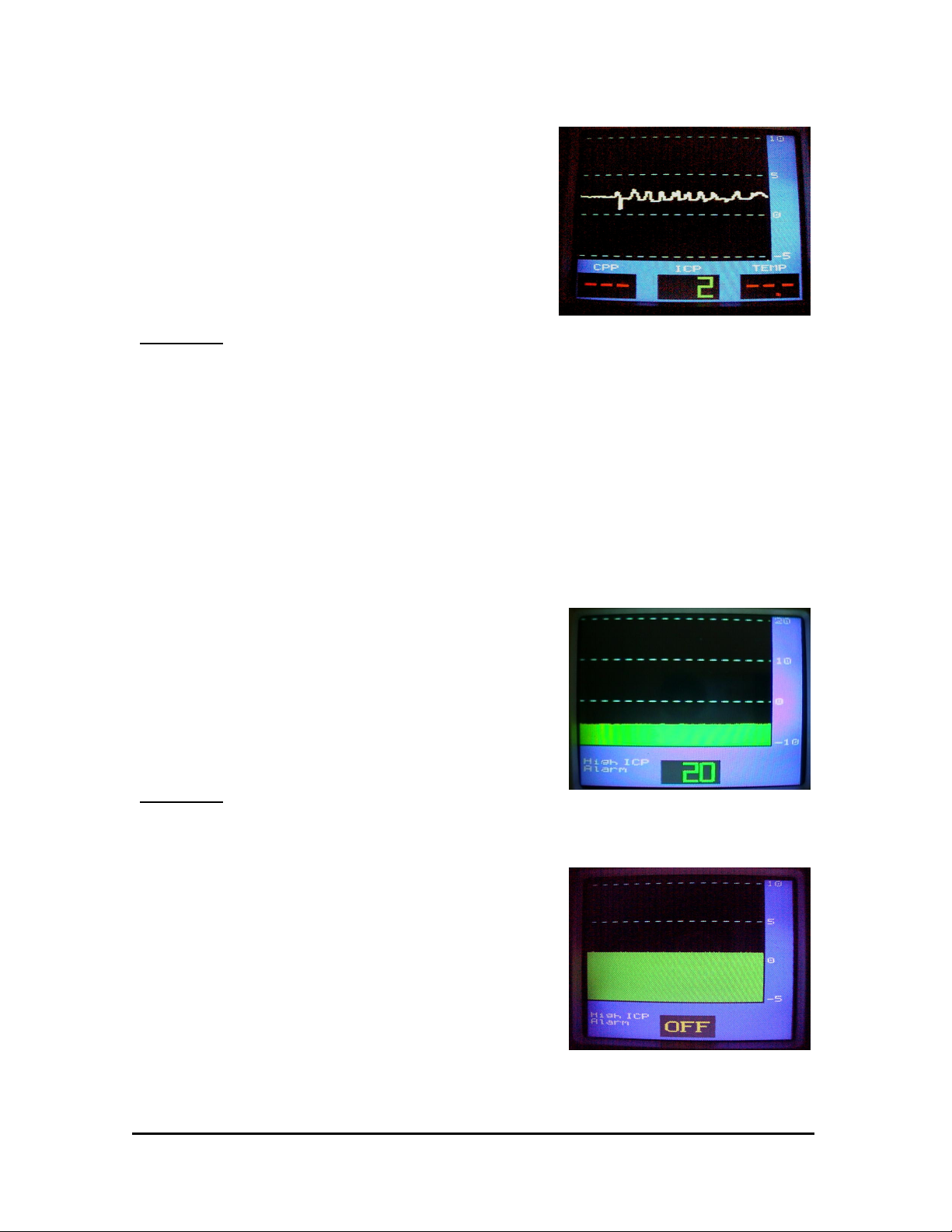
Figure 3-19 High ICP Alarm
4. Turn on the MPM-1 and set the High ICP Alarm to 4 mmHg by pressing the UP-
ARROW.
5. Set the pressure source to 10 mmHg. The MPM-1 should display approximately 10
± 2 mmHg. After approximately 5 seconds, the alarm speaker should beep.
6. Silence the alarm by pressing the SILENCE ALARM button. The ALARM
DISABLED INDICATOR and ICP parameter should flash.
7. Wait approximately 3 minutes, and the alarm should resume beeping.
8. Decrease simulated pressure to 0 mmHg, and the alarm should silence.
9. Set High ICP Alarm to “OFF”.
40201–C
3-16 MPM-1 Technical Manual
Page 49

3.1.9 Arterial Pressure Test
1. Connect a Pre-Amp cable to the ICP and Temperature connections of MPM-1.
2. Using a functional Camino catheter, firmly connect the pressure transducer
connector to the Pre-Amp cable (PAC-1). Zero adjust the catheter. Do not connect
the temperature transducer connector if you are using a 110-4BT or 110-4HMT
model catheter.
3. Connect a PMIO cable to the rear connector of MPM-1, but do not connect to an
external bedside monitor.
4. Using a power supply, provide 1.000 ± 0.001 volts to the Arterial Pressure
connector (see Figure 3-20).
_
+
Figure 3-20 Arterial Pressure Connector
Note: AP = 1V/100 mmHg.
5. Turn on MPM-1. Wait until the CPP-ICP-ICT display appears. CPP parameter
should read 100 mmHg ± 1 mmHg since AP = 100 mmHg and ICP = 0 mmHg.
Note: CPP = AP-ICP.
40201–C
3-17 MPM-1 Technical Manual
Page 50

3.1.10 Low CPP Alarm
1. Connect a Pre-Amp cable to the ICP and Temperature connections of MPM-1.
2. Using a functional Camino catheter, firmly connect the pressure transducer
connector to the Pre-Amp cable (PAC-1). Zero adjust the catheter. Do not connect
the temperature transducer connector if you are using a 110-4BT or 110-4HMT
model catheter.
3. Connect tip of catheter to a pressure source. Make sure that tip of catheter fits firmly
to the pressure source with no leaks.
4. Connect a PMIO cable to rear connector of MPM-1, but do not connect to an
external bedside monitor.
6. Using a power supply, provide 1.000 ± 0.001 volts to the Arterial Pressure
Connector (see Figure 3-20).
5. Turn on MPM-1.
Figure 3-21 Low CPP Alarm
7. Set the LOW CPP ALARM to 4 mmHg by pressing the DOWN-ARROW. Set
pressure source to 98 mmHg. The CPP parameter should display 2 mmHg since
CPP = (100-98) mmHg. This value is lower than the value set in the alarm mode.
After approximately 5 seconds, the alarm speaker should beep.
8. Silence the alarm by pressing the SILENCE ALARM button. The ALARM
DISABLED INDICATOR and the CPP parameter should flash. Wait
approximately 3 minutes, and the alarm should resume beeping.
9. Decrease the value from pressure source to 92 mmHg. The alarm should silence
since now CPP = 8 mmHg which is greater than the value set in the alarm mode.
10. Increase simulated pressure to 98 mmHg (CPP = 2 mmHg), and the alarm should
resume beeping.
40201–C
3-18 MPM-1 Technical Manual
Page 51

11. Set LOW CPP ALARM to “OFF” by pressing the DOWN-ARROW. The alarm
should silence, and at this point the SILENCE ALARM INDICATOR will
illuminate since both alarm parameters, HIGH ICP ALARM and LOW CPP
ALARM, are set to “OFF”.
12. Set pressure source to 0 mmHg. Turn off MPM-1.
13. Disconnect power supply from AP connector.
40201–C
3-19 MPM-1 Technical Manual
Page 52

3.1.11 ICP Output Test
1. Connect a Pre-Amp cable to the ICP and Temperature connections of MPM-1.
2. Using a functional Camino catheter, firmly connect the pressure transducer connector
to the Pre-Amp cable (PAC-1).
3. Connect a PMIO cable to the rear connector of MPM-1, but do not connect to an
external bedside monitor.
5
(- PS) 4
(- DMM) 3
Figure 3-22 PMIO Connector
6
1 (+ PS)
2 (+ DMM)
4. Set power supply to 5 ± 0.001 volts and connect “+” and “-” leads to pins “1” and
“4” of the six pin cannon connector, respectively.
5. Connect the “+” and “-” leads of the Digital Multimeter (DMM) to pins “2” and
“3” of the six pin cannon connector, respectively.
6. Turn on monitor, and wait until the CPP-ICP-ICT display appears.
7. Press and hold the CAL STEP to produce 0 mmHg on the display. The DMM
should read less than .010 mVDC offset from 0 volts. The following table shows
simulated pressures by pressing and holding the CAL STEP button, and expected
voltages at pins “2” and “3”.
8. Turn off MPM-1. Remove power supply and DMM leads from PMIO cable
connector.
Table 3-5 Simulated Pressure & Voltage
Simulated Pressure (mmHg) Simulated Voltage (mVDC)
0
20
40
100
200
0.000 ± .001 mVDC
0.500 ± .001 mVDC
1.000 ± .001 mVDC
2.500 ± .001 mVDC
5.000 ± .001 mVDC
40201–C
3-20 MPM-1 Technical Manual
Page 53

3.1.12 ICT Input Test
2
(Vin)
1
(1Volt)
Figure 3-23 Temperature Transducer Connector
1. Connect a Pre-Amp cable to the ICP and Temperature connections of MPM-1.
2. Using a functional Camino catheter, firmly connect the pressure transducer connector
to the Pre-Amp cable (PAC-1).
3. Connect the leads of the Digital Multimeter (DMM) to pins 1 (1 Volt) and 3 (GND)
of Pre-Amp cable (PAC-1) temperature connector (Figure 3-23). Note: The ICT
parameter should be reading “---“ up to this point.
3
(GND)
4. Turn on the monitor, and the DMM should read 1.0000 ± 0.0001 VDC.
5. Turn off MPM-1, and remove DMM leads from temperature connector.
10KΩ
2
Vin
.350V = 30.0°C
.438V = 40.0°C
10KΩ
3
GND
Figure 3-24
Temperature Transducer
Connector Test Circuit Diagram
10KΩ
Adjust this pot for the
voltages at Pin
2 above.
1
1 Vol
t
6. Connect two 10KΩ resistors and a 10KΩ potentiometer to the temperature transducer
connector as shown in Figure 3-24. Connect the leads of the Digital Multimeter
(DMM) to pins 2 (Vin) and 3 (GND).
7. Turn on MPM-1, and adjust the 10KΩ potentiometer to produce a reading on the
DMM of 0.350 VDC. The monitor should display 30.0 ± 0.3°C.
8. Adjust the 10KΩ potentiometer to produce a reading on the DMM of 0.438 VDC.
The monitor should display 40.0 ± 0.3°C.
9. Turn off MPM, and remove all components from the temperature connector.
40201–C
3-21 MPM-1 Technical Manual
Page 54

3.1.13 ICT Output Test
+
__
Figure 3-25 ICT Output Connector
1. Connect a Pre-Amp cable to the ICP and Temperature connections of MPM-1.
2. Using a functional Camino catheter, firmly connect the pressure transducer connector
to the Pre-Amp cable (PAC-1).
3. Connect a PMIO cable to the rear connector of MPM-1, but do not connect to an
external bedside monitor.
4. Connect the Digital Multimeter (DMM) leads to Switchcraft ¼” connector and set
DMM to ohms.
5. Press and hold the UP arrow, then press and release the START/STOP button. Do
not release the UP arrow until the MPM-1 displays “STUCK KEYBOARD” in red
color. The DMM should read a resistance value between 3465.9Ω and 3608.1Ω. The
nominal value is 3537.0Ω.
6. Press and release the UP arrow, and the resistance value will change to the next value
shown in Table 3-6. Repeat this step until all resistance values are verified.
Table 3-6 Output Temperature Resistances
LOW Ω NOMINAL Ω HIGH Ω
3465.9 3537.0 3608.1
3431.7 3501.4 3571.1
3398.1 3466.5 3534.8
3332.6 3398.2 3463.8
3208.5 3269.3 3330.1
2984.7 3037.3 3089.8
2635.7 2676.4 2717.1
2121.7 2141.8 2161.9
1525.1 1535.4 1545.7
4. Disconnect DMM, and turn off monitor.
40201–C
3-22 MPM-1 Technical Manual
Page 55

3.1.14 Isolated Analog Output Test
Connect a Pre-Amp cable to the ICP and Temperature connections of MPM-1.
Using a functional Camino catheter, firmly connect the pressure transducer connector to
the Pre-Amp cable (PAC-1).
Isolated
Cable
Figure 3-26 Isolated Analog Connector
Isolated
Analog
Connector
1. Connect one end of cable to the isolated analog output of the MPM-1, and the other
end to a Digital Multi Meter (DMM).
2. Turn ON the MPM-1, and wait until the CPP-ICP-ICT display appears.
3. Press and hold CAL STEP. Verify that the MPM-1 and DMM display “0 mmHg”
and “0.000 ± .001 mV” respectively. The following table shows simulated pressures
and voltages by pressing and holding the CAL STEP button.
Table 3-7 Isolated Analog Voltage Output
MPM-1 DISPLAY
(mmHg)
Multi-Meter Display
(VDC)
0 0.0
20 0.2
40 0.4
100 1.0
200 2.0
6. Turn off MPM-1 once pressures and voltages are verified. Remove analog cable
and DMM.
40201–C
3-23 MPM-1 Technical Manual
Page 56

3.1.15 Ground Continuity Test
Note – This procedure assumes use of a Bio-Tek Model 170 safety tester. If a different
safety tester is used, check safety tester’s instructions for proper operation.
1. Plug the Bio-Tek Model 170 safety tester into an A.C. outlet.
2. Ensure that only the two "OK" neon lamps on the Bio-tek front panel illuminate.
3. Turn the Model 170 on using the On/Off switch.
4. The Model 170 display should indicate LINE VOLTAGE of 120 ± 10 volts for
domestic units and 220 ± 10 volts for international units.
5. Connect one end of the AC power cord to the back of the MPM-1. Connect the other
end of the AC power cord to the Model 170.
6. Turn the GROUND switch on the Model 170 to the NORMAL position.
7. Turn the Model 170 function selector to GROUND WIRE RESISTANCE position.
8. Set the Model 170 POLARITY switch to OFF.
9. Connect the Model 170 ground probe to the equipotential plug on the back panel of
the MPM instrument.
10. Check that the Model 170 display indicates less than 0.10 ohms.
11. If resistance read is higher than 0.10 ohm, check for damaged power cord or bad
power cord connections. If the problem cannot be solved, return unit to Integra
NeuroSciences for service.
40201–C
3-24 MPM-1 Technical Manual
Page 57

3.1.16 Chassis Leakage Test
Note – This procedure assumes use of a Bio-Tek Model 170 safety tester. If a different
safety tester is used, check safety tester’s instructions for proper operation.
1. Plug the Bio-Tek Model 170 safety tester into an A.C. outlet.
2. Ensure that only the two "OK" neon lamps on the Bio-tek front panel illuminate.
3. Turn the Model 170 on using the On/Off switch.
4. The Model 170 display should indicate LINE VOLTAGE of 120 ± 10 volts for
domestic units and 220 ± 10 volts for international units.
5. Connect one end of the AC power cord to the back of the MPM-1. Connect the other
end of the AC power cord to the Model 170.
6. Turn the GROUND switch on the Model 170 to the NORMAL position.
7. Turn the Model 170 function selector to CHASSIS LEAKAGE position.
8. Touch the equipotential plug on the MPM back panel with the Model 170 probe.
9. Check
following POLARITY switch positions:
NORMAL
REVERSE
10. Set the Model 170 GROUND switch to OPEN.
11. Set the Model 170 POLARITY switch to OFF. Disconnect the instrument.
12. If the chassis leakage is found higher than specified above, return unit to Integra
NeuroSciences for service.
that the Model 170 display indicates less than 12 micro amperes for the
Ensure that the display reads less than or equal to 120 micro amperes for domestic
units (MPM-1-6).
Ensure that the display reads less than or equal to 180 micro amperes for
international units (MPM-1-7).
40201–C
3-25 MPM-1 Technical Manual
Page 58

3.2 Battery Replacement
CAUTION – Ensure that the unit is turned off and the power cord has been removed
from the unit before attempting this procedure.
(+) Terminal
Spade Lug
Connectors
Battery
Compartment Slide
(-) Terminal
Figure 3-27 Battery Compartment
1. Using a flat bladed screwdriver, carefully lift off the battery compartment door, by
inserting the screwdriver into the battery compartment notch and twisting.
2. Move the metal battery compartment slide in the direction indicated to open.
3. Remove the spade lug connectors from the positive and negative terminals.
4. Gently slide the battery out of the battery compartment.
5. Replace the battery in the battery compartment.
6. While observing polarity, reconnect the spade lug connectors to the battery terminals.
The “+” wire to the positive terminal and the “-” wire to the negative terminal. Ensure
that the black side of the battery is on the right side.
7. Move the metal battery compartment slide in the direction indicated until it is closed.
8. Replace the battery compartment door and snap into place.
9. Dispose of old battery properly, per applicable and local regulations.
40201–C
3-26 MPM-1 Technical Manual
Page 59

3.3 Bedside Monitor Calibration
Cal Step
Figure 3-28 Cal Step Button
1. Connect the MPM-1 to an external bedside monitor.
2. With a catheter connected, energize the MPM-1.
3. Press the CAL STEP button repeatedly until 0 mmHg is displayed on the MPM-1.
Note – The CAL STEP momentarily interrupts normal pressure signal on both the
MPM-1 and on the external bedside monitor.
4. While keeping the button depressed to maintain 0, simultaneously zero the bedside
monitor.
5. Press the CAL STEP button to advance to the next mmHg value in the following
series: 0, 20, 40, 100, 200 and back to 0. Verify the bedside monitor reading at each
step.
6. Release the CAL STEP button. Within a few seconds, the MPM-1 will return to the
pressure display.
Note – The CAL STEP button may be used at any time, and does not affect the
transducer calibration.
40201–C
3-27 MPM-1 Technical Manual
Page 60

4 Troubleshooting
4.1 Introduction.......................................................................................................... 4-2
4.2 Power Supply Malfunctions................................................................................. 4-3
4.3 LCD Malfunctions ............................................................................................... 4-4
4.4 Error Messages..................................................................................................... 4-5
4.5 Cabling and Interfacing Problems ....................................................................... 4-7
40201–C
4-1 MPM-1 Technical Manual
Page 61

4.1 Introduction
The troubleshooting guide is intended to resolve problems that may occur while using the
MPM-1. This section contains troubleshooting isolation tables. If the difficulty persists
after attempting to troubleshoot, or if a problem other than those described below occurs,
routine technical assistance may be obtained by contacting Integra NeuroSciences.
Note: If it is necessary to return the MPM-1 monitor or catheter to Integra
NeuroSciences, please provide a detailed description of the problem and any errors which
were shown. This will assist in the proper servicing of your equipment. Please call
Integra NeuroSciences for specific instructions on returned goods procedures.
40201–C
4-2 MPM-1 Technical Manual
Page 62

4.2 Power Supply Malfunctions
Symptom Possible Cause Corrective Action
MPM-1 does not operate on
AC power, but system
works on battery.
MPM-1 does not operate on
battery, but system operates
on AC power.
Or
Battery does not charge.
AC power cord not
connected.
Faulty AC power cord. Replace power cord.
Blown fuse. Replace fuse.
Power module
malfunctioning.
Faulty battery. Connect to AC power for
Battery terminal wires were
reversed.
Verify power cord is
plugged into a live AC
power source.
Send unit in for service.
24 hours to fully charge
battery. The MPM-1 may
be used on AC while
charging. If battery does not
charge, replace battery.
Refer to section 3.2 in
TESTING and
PREVENTIVE
MAINTENANCE.
Send unit in for service.
ON and OFF button does
not work properly.
Faulty membrane switch
and/or power supply.
Send unit in for service.
40201–C
4-3 MPM-1 Technical Manual
Page 63

4.3 LCD Malfunctions
Symptom Possible Cause Corrective Action
MPM-1 is operating, but a
dark display is present.
OR
LCD displays white vertical
lines or a certain color is
dominant.
Faulty LCD or connections. Send unit in for service.
40201–C
4-4 MPM-1 Technical Manual
Page 64

4.4 Error Messages
Symptom Possible Cause Corrective Action
MPM-1 Display reads:
“CHECK CATHETER
CONNECTION”
ICP, Systolic or Diastolic
reads: “---“
Defective external
connection.
Damaged catheter. Replace catheter.
Faulty Pre-Amp cable. Replace Pre-Amp cable.
Faulty connection between
Analog Board and Pre-Amp
flex cable at J1.
Faulty Digital Board or
Analog Board.
Value outside operating
range of MPM-1 (-50
mmHg to 300mmHG).
Imperfect connection
between Pre-Amp cable and
MPM-1.
Damaged Catheter. Replace Catheter.
Damaged Pre-Amp cable. Replace Pre-Amp cable.
Check connection between
Catheter, Pre-Amp cable
and MPM-1.
Send unit in for service.
Send unit in for service.
Check connection between
catheter and Pre-Amp cable.
Check connection between
Pre-Amp cable and MPM-1.
Faulty connection between
Analog Board and Pre-Amp
flex cable.
Faulty Digital or Analog
Board.
Send unit in for service.
Send unit in for service.
40201–C
4-5 MPM-1 Technical Manual
Page 65

Symptom Possible Cause Corrective Action
CPP reading “---“.
ICT reads:”---“
Value outside operating
range of MPM-1 (0 mmHg
to 210 mmHg).
Faulty connection between
bedside monitor and MPM-
1.
Check connection between
catheter, Pre-Amp cable and
MPM-1.
Check connection between
PMIO cable and Bedside
Monitor.
Defective Adapter Cable. Replace adapter cable.
Defective PMIO cable. Replace PMIO cable.
Damaged catheter. Replace catheter.
Faulty Pre-Amp cable. Replace Pre-Amp cable.
Faulty bedside monitor. Replace bedside monitor.
Faulty connection between
Send unit in for service.
PMIO flex cable and
Analog Board.
Malfunction of Analog
Send unit in for service.
Board.
Value outside operating
range of MPM-1 (15°C to
45°C).
Check connection between
catheter temperature
connector, Pre-Amp cable
and MPM-1.
40201–C
Faulty catheter. Replace catheter.
ICP only catheter in use. Replace catheter.
Damaged Pre-Amp cable. Replace Pre-Amp cable.
Faulty connection between
Send unit in for service.
Temperature cable and
Analog Board.
Malfunction of Analog
Send unit in for service.
Board.
4-6 MPM-1 Technical Manual
Page 66

4.5 Cabling and Interfacing Problems
Symptom Possible Cause Corrective Action
Discrepancy in pressure
reading between the MPM1 and the host monitor.
Discrepancy in temperature
reading between the MPM1 and the host monitor.
No pressure waveform or
numerical display on host
monitor, but MPM-1
displays mean pressure.
Host monitor out of
calibration.
Incorrect host monitor
adapter cable being used.
Faulty PMIO cable. Replace PMIO cable.
Incorrect host monitor
adapter cable being used.
Faulty PMIO cable. Replace PMIO cable.
PMIO or host monitor
adapter cable is loose.
PMIO cable or monitor
adapter cable is faulty.
Re-calibrate or re-zero the
Host monitor using the
MPM-1 CAL STEP button.
Refer to section 3.3 in
TESTING AND
PREVENTIVE
MAINTENANCE.
Verify correct host monitor
cable is used.
Verify correct host monitor
cable is used.
Check cable connections
between host monitor and
MPM-1.
Replace cable.
No temperature waveform
or numerical display on host
monitor, but MPM-1
displays mean temperature.
Host monitor
malfunctioning.
Faulty connection between
PMIO flex cable and
Analog Board.
PMIO cable or monitor
adapter cable is faulty.
Host monitor
malfunctioning.
Imperfect connection
between PMIO flex cable
and Analog Board.
Verify proper operation of
host monitor.
Send unit in for service.
Replace cable(s).
Verify proper operation of
host monitor.
Send unit in for service.
40201–C
4-7 MPM-1 Technical Manual
Page 67

Symptom Possible Cause Corrective Action
Host monitor displays
numerical or waveform
Arterial Pressure. MPM-1
displays numerical ICP, but
does not display CPP.
No Isolated Analog Output.
No RS-232 communication.
PMIO or host monitor
adapter cable is loose.
Check cable connections
between host monitor and
MPM-1.
PMIO cable or monitor
Replace cable(s).
adapter cable is faulty.
Faulty connection between
Send unit in for service.
PMIO flex cable and
Analog Board.
Loose cable. Reconnect cable.
Faulty Cable. Replace cable.
Faulty Connection between
Send unit in for service.
Analog Board and Isolated
Analog Output Cable.
Loose cable Reconnect cable.
Faulty Cable. Replace cable.
Faulty Connection between
Send unit in for service.
Digital Board and RS-232
cable.
40201–C
4-8 MPM-1 Technical Manual
 Loading...