

Page 1
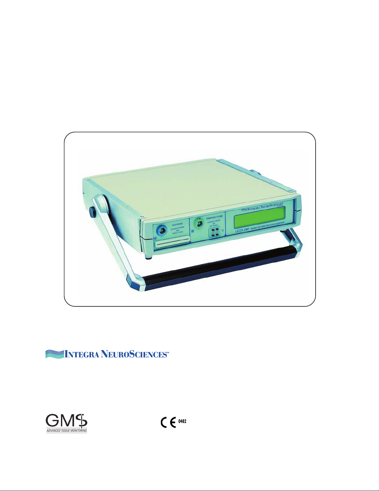
LICOX® CMP
Brain Oxygen Monitoring System
Operations Manual
.
Distributed by:
Integra NeuroSciences
311 Enterprise Drive, Plainsboro, New Jersey 08536 USA
Tel.: 800-654-2873
Outside the US: 609-275-0500, Fax: 609-275-5363
www.Integra-NeuroSciences.com
Manufacturer:
GMS - Gesellschaft für Medizinische Sondentechnik mbH
Dorfstraße 2, D-24247 Kiel-Mielkendorf, Fed. Rep. Germany
Tel +49(0)4347 7051 0, FAX +49(0)4347 705129, e-mail:[email protected]
Page 2

Contents
1 Introduction ..................................................................................................................... 3
2 Indications for Use .......................................................................................................... 3
3 Important Notes ...............................................................................................................3
Device Classifications and Standards .....................................................................................3
Warning Instructions................................................................................................................4
4 Oxygen Sampling Method .............................................................................................. 5
5 Operation and Display .................................................................................................... 7
Front Panel of the LICOX CMP Monitor .................................................................................. 7
Rear Panel of the LICOX CMP Monitor ...................................................................................8
Handle of the LICOX CMP Monitor .........................................................................................8
The LCD Display .....................................................................................................................8
Explanation of the Symbols on the Front and Rear Panel ..................................................... 10
6 Components of the LICOX CMP System ..................................................................... 11
Instruments, Cables and Accessories ...................................................................................11
Optional accessories used in displaying the measured data with other monitoring systems 11
Disposable Catheter Probe and Bolt .....................................................................................12
Temperature catheter microprobes .......................................................................................15
7 Explanation of the Symbols on the Packaging of Sensors and Accessories.......... 16
8 System Set Up ............................................................................................................... 17
Assembly ...............................................................................................................................17
Functional Check of the System ............................................................................................17
Connecting the LICOX CMP to other Devices ....................................................................... 18
9 Measuring pbtO2............................................................................................................. 18
Checks Prior to Monitoring ....................................................................................................18
Connecting the Probe/Starting the Measurement/Temperature Compensation .................... 18
Data Recording .....................................................................................................................19
Plausibility Check ..................................................................................................................20
Checking probe zero after removal from patient ................................................................... 21
Sensor Implantation Technique .............................................................................................21
Troubleshooting.....................................................................................................................22
Problems due to instrument malfunction ...............................................................................22
Fault in operation ................................................................................................................... 23
Risks to the patient ................................................................................................................23
Artifact ...................................................................................................................................25
10 Cleaning, Disinfection, Sterilization and Disposal ................................................... 26
The Instrument ......................................................................................................................26
The Cables ............................................................................................................................26
Probes and Other Disposables .............................................................................................26
Disposal of Probes and Disposable Accessories ..................................................................27
11 Maintenance................................................................................................................. 28
Periodic Checks to be Carried Out by the User.....................................................................28
12 Technical Specifications ............................................................................................ 30
LICOX CMP Instrument .........................................................................................................30
Appendix ........................................................................................................................... 32
Terms of Sale .................................................................................................................... 33
Integra NeuroSciences Limited Warranty ...................................................................... 34
2
Page 3

1 Introduction
The LICOX CMP instrument is used for continuous determination of oxygen partial pressure (pbtO2) in cerebral spinal fluid and brain tissue. Minimally invasive catheter micro-
probes are implanted directly into brain tissue and are connected to the CMP monitor
via an electrical cable. Tissue temperature can also be continuously measured and
used for temperature compensation of p
sensing catheter is used.
In clinical use however, the LICOX CMP instrument can not be used for blood gas
monitoring.
measurements, if a separate temperature
btO2
The catheter employs an electrochemical (polarographic)
ing. The temperature catheter employs a (type K) thermocouple.
Due to its smart card technology, minimal time and effort is required to calibrate the
system before use. Calibration data is stored on a smart card supplied with each catheter. When the smart card is inserted into the LICOX CMP instrument, the system calibrates automatically and is ready for use. Oxygen catheters may be disconnected during use and re-connected to any CMP monitor, as long as the catheter and it’s smart
card are connected to the same CMP monitor. A catheter implanted in the ER can be reconnected to a second CMP unit located in the ICU or elsewhere.
The LICOX CMP data can be displayed in the following ways:
• The LICOX CMP instrument can be used as a simple stand alone
monitor with digital display of the pbtO2 values.
• The oxygen pressure and temperature data measured by the LICOX system may
also be sent to patient monitors, e.g. Hewlett Packard, Marquette, etc., for display,
storage and processing. This is accomplished by the use of the LICOX LML interface
device and cables.
micro-cell for oxygen sens-
2 Indications for Use
The LICOX Brain Oxygen Monitoring System measures intracranial oxygen and temperature and is intended as an adjunct monitor of trends of these parameters, indicating
the perfusion status of cerebral tissue local to sensor placement. LICOX System values
are relative within an individual, and should not be used as the sole basis for decisions
as to diagnosis or therapy. It is intended to provide data additional to that obtained by
current clinical practice in cases where hypoxia or ischemia are a concern.
3 Important Notes
Device Classifications and Standards
This instrument has been designed for constant use.
Electrical safety meets EN 60601-1 (including amendments 1 and 2), Type CF.
Immunity from electromagnetic disturbance meets IEC 801 including ext. No. 2, 3, 4, 5.
Maximum electromagnetic emission meets EN 55011, Group 1, Class B.
3
Page 4
Warning Instructions
Failure to observe one or more of the following warnings could compromise the safety of
the patient or result in measurement errors. This also applies to warnings that are issued at other locations throughout this operation manual; sections in which reference is
made to dangers or to possible operating errors are marked in this document with an
index-finger symbol "
a The LICOX CMP instrument may only be used per the “Indications for
Use” section of this document.
b The LICOX CMP instrument may only be used when device mainte
nance has been carried out.
c The use of excessive force on the instrument may seriously damage it;
the same applies to the cable and to the sensor. All mechanical fea
tures of the LICOX system can be operated without the use of exces
sive force.
d The housing of the unit and/or the wall power supply must not be opened.
Units must be returned to the manufacturer for repair and service.
e Only original LICOX parts may be used with or on the instrument. This
applies in particular to all pbtO2 probes, probe cables, analog
transmission cables and the power supply.
":
f The instrument, the power supply and the cable connectors must be
protected against moisture and wetness.
g The instrument must be switched off before cables are connected or
disconnected at the rear of the device.
h Probe cables (or extension probe cables) with damaged isolation
jacketing must not be used. Connector contacts must be cleaned after
coming into contact with saline solutions or body fluid. Measurement
error can occur if these recommendations are not observed.
i Probe extension cables may not be used when their connectors are wet
or damp. Measurement errors can occur if this recommendation is not
observed.
j The potential equalisation plug at the rear of the device must be
connected to the hospital grounding system, when available.
k The anesthetic gas halothene disturbs measurement with all types of
polarographic pbtO2 probes. After an initial exposure time of 5 to 20
min., the displayed pbtO2 value is overestimated; this effect is usually
reversible. However, other common anesthetic gases such as nitrous
oxide (N2O), enflurane and isoflurane can be used without impairing
the accuracy of the measurement.
l Strong electrical interference (e.g. during cauterization) can cause a
disturbance of the measurement that outlasts the interference by a few
seconds.
4
Page 5
m The device has not been designed for use in areas where there is a risk
of explosion.
n Only use the prescribed cleaning agents and methods when cleaning
and disinfecting the instrument and the cable.
o Disposable probes and accessories are for single use only.
p In hyperbaric medicine, the instrument may be used in an air-filled (not
enriched with O
!) pressure chamber up to a pressure of 3 bar. The
2
power supply (low voltage DC) is connected through the wall of the
chamber from the outside using suitable connectors. On precisely speci
fied demand, a custom-made cable can be obtained from the manufac
turer, or the manufacturer of the pressure chamber. This authorization
to use the LICOX CMP in a pressure chamber does not extend to
connected devices. It is, however, generally recommended as a sim
pler technical solution for measurement during Hyperbaric Oxygenation
(HBO), that the LICOX CMP instrument is set up outside the chamber
and that the probe signals be transmitted via bi-polar electrical bush
ings. A description of the technical details can be obtained from the
manufacturer upon request.
q The measurement error can exceed the defined limits when the cath
eter is continuously operated for more than 5 days.
r Facilities for neurosurgical treatment of an intracranial bleed must be
available in the hospital.
s Accessory equipment connected to the analogue and digital interfaces
must be certified according to the respective UL standards (UL2601 for
medical equipment). Furthermore all configurations shall comply with
the system standard UL2601. Anyone who connects additional equip
ment to the signal input part or signal output part configures a medical
system, and is therefore responsible that the system complies with the
requirements of the systems standard IEC60601-1. If in doubt consult
the technical service department.
t This equipment is not a bloodgas device .
u Disconnect the power supply from outlet to separate from main voltage
4 Oxygen Sampling Method
Relationship between oxygen pressure and oxygen content in biological media
Gases which are in contact with the surface of a liquid become physically dissolved in
the liquid. If the pressure, the composition and the temperature of the gas atmosphere
over the liquid remain constant over time, a stable equilibrium of diffusion is established
between the gas and the liquid. Ultimately, the pressure of the gas dissolved in the liquid
reaches the pressure of the gas above the liquid. The partial pressure of a gas dissolved
5
Page 6

in a liquid is often expressed in units of mmHg, pressure units which correspond to the
pressure exerted by a column of mercury of a given height.
As partial pressure increases, the amount of gas that is dissolved in a particular volume
of liquid also increases. In other words: the higher the partial pressure of a gas in solution, the higher the concentration.
The pbtO2 value, a measure of cellular oxygen availability
The partial pressure of the oxygen physically dissolved in CSF or brain tissue corresponds to the availability of oxygen at the cellular level, since the cell membranes do
not represent a functionally variable O2 diffusion barrier and because the diffusion distance between the interstitial space and the mitochondria is short. Hence the pbtO
value reflects the balance between O2 supply and O2 demand of the oxidative energy
metabolism directly at the target of the complex oxygen transport. An increase in the
pbtO2 balance might be due to an increase in the oxygen transport rate to tissue or to a
decrease of the tissue oxygen consumption.
Temperature effect
The signal of a polarographic pbtO2 probe (the probe current) changes depending on
the temperature, even if the pbtO2 value in the environment remains constant. The change
in probe pbtO2 sensitivity with change in temperature is approximately 4% per degrees
centigrade. The probes zero signal (current with no oxygen present) does not depend
on temperature. The temperature sensitivity of the probe signal is compensated for
when the monitor calculates the pbtO2 value. Therefore the temperature of the pbtO
probe must be supplied to the LICOX CMP instrument. The temperature must be continuously measured by an additional LICOX temperature probe (recommended when
the tissue temperature is variable or unknown) or the tissue temperature must be supplied by adjusting a code switch on the front panel of the instrument. The second option
may be preferred when the patient‘s core temperature is continuously monitored, for
example by the use of a foley catheter with thermistor.
2
2
Microtrauma caused by catheter implantation
A local microtrauma results from the implantation of the p02 probe in the tissue. Tissue
is affected in a layer concentrically surrounding the catheter. Several hours after implantation the thickness of that layer is 70 µm to 500 µm.
The pbtO2 value measured corresponds to the mean value of the local pbtO2 levels at
the interface between the damaged tissue around the sensor and the surrounding undamaged tissue. Tissue lacking oxidative metabolism is transparent to the pbtO2 measurement. Therefore, the reading is predominantly determined by the pbtO2 in the undamaged tissue.
Immediately after implantation of the pbtO2 catheter, readings are influenced by the
developing microtrauma. This applies to the first 10 to 120 minutes after insertion. The
pbtO2 values displayed during this initial phase after implantation therefore do not provide relevant information about the oxygenation of the tissue.
6
Page 7

5 Operation and Display
Front Panel of the LICOX CMP Monitor
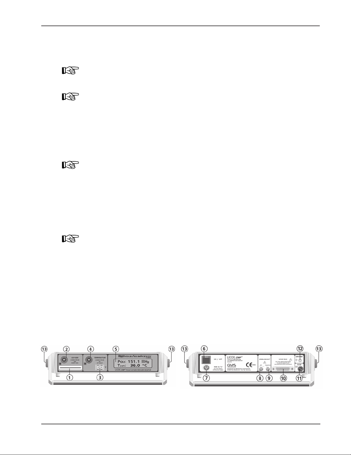
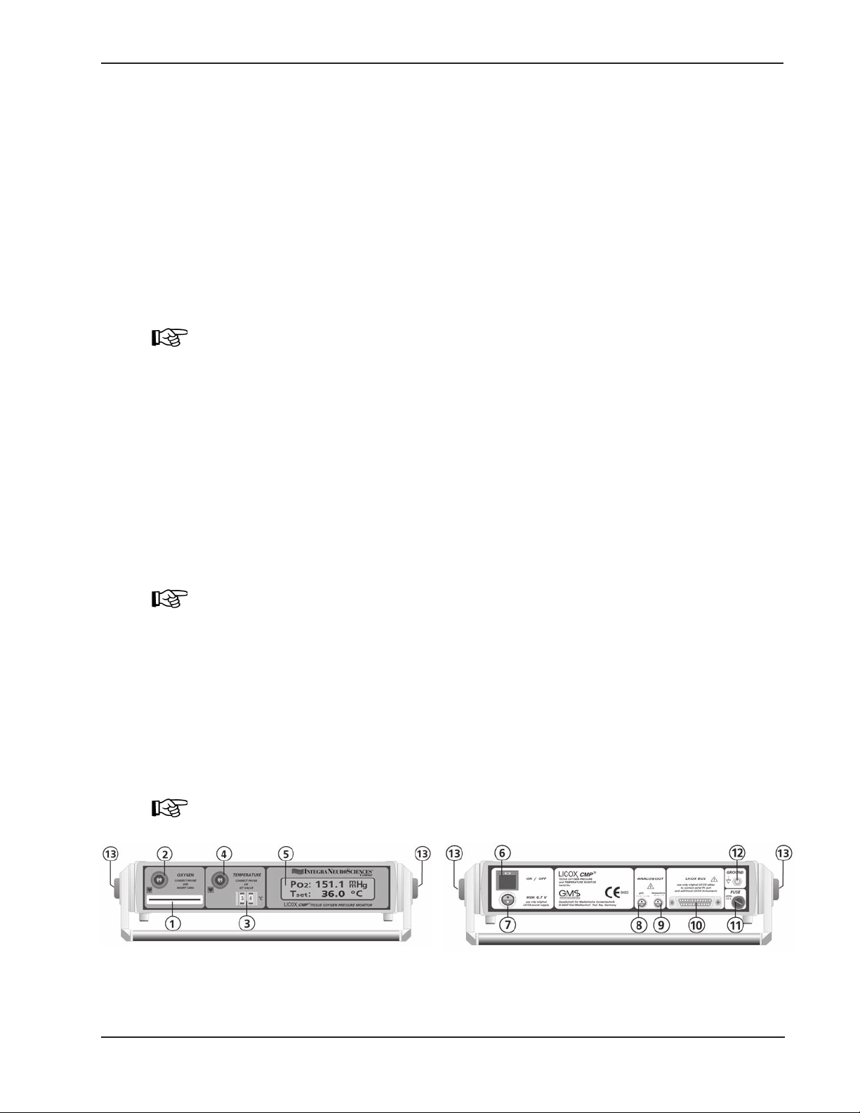
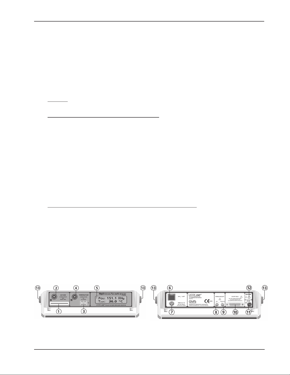
1 Slot for smart card
2 Blue socket for blue cable (REF: BC10PA), cable that connects the pbtO2 probe
3 Code switch for input of patient tissue temperature
4 Green socket for green cable (REF: BC10TA), cable that connects to tissue tem-
perature probe
5 LCD display. Measured data, instructions and error messages
Fig. 1: Front Panel of the LICOX CMP Monitor
7
Page 8
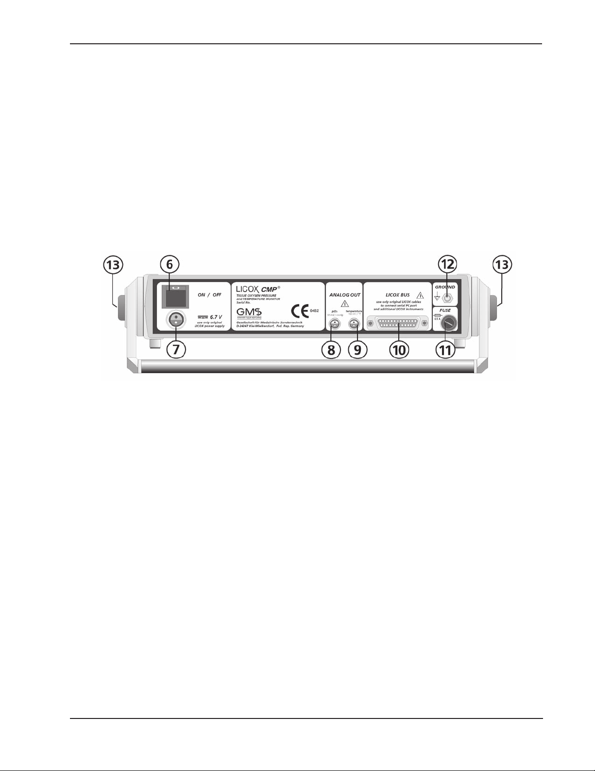
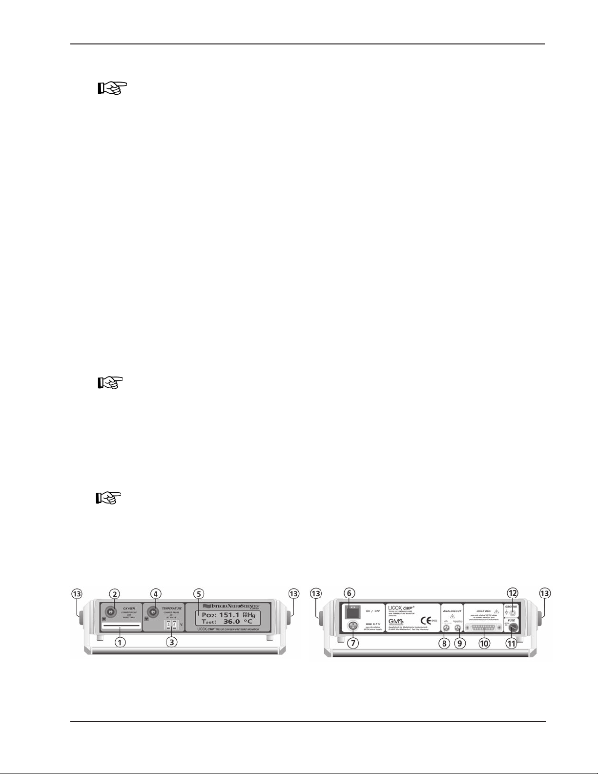
Rear Panel of the LICOX CMP Monitor
6 On/Off switch
7 Socket for connection of the LICOX main power supply (6.7 - 7.5 VDC), (REF: A10)
8 Analog pbtO2 signal output (0 to 10 V DC, 10 mV/mmHg)
9 Analog temperature signal output (0 to 10 V DC, 100 mV/°C)
10 LICOX bus socket
The analog signal output (No. 8 of Fig. 2) and bus socket (No. 10 of Fig. 2) may
be connected (by using the cable REF D11) to the LICOX monitor Link A for
p
11 Fuse (500 mA, slow-acting)
12 Potential equalisation plug
signal transfer to a bedside monitor. (See Directions for Use, REF: LML.1.)
btO2
Fig. 2: Rear Panel of the LICOX CMP Monitor
Handle of the LICOX CMP Monitor
13 By simultaneously pressing firmly on the buttons on both sides of the handle, the
handle is unlocked. It can then be rotated to a new position and again locked.
8
Page 9

The LCD Display
Identification of parameters
pbtO2pbtO2 value (0.0 - 1999 mmHg), calculated from the probe current signal and
the compensation temperature
T
T
SET
mp
patient temperature (28 - 45 °C) set at code switch (No. 3 of Fig. 1)
temperature (0.0 - 46.0°C) measured by the LICOX thermocouple probe con-
nected to the monitor. In tissue, the thermocouple should be near the location
of the p
btO2
probe.
Messages on the LCD display
"please insert probe card"
Insert the smart card until it snaps into the chip card slot (No. 1 of Fig. 1). The gold
contact pads must point downwards. Push the card in the direction of the arrow labeled
on the card until the card snaps into place.
"card orientation wrong -> re-insert"
The smart card has been inserted incorrectly; turn the chip card over and re-insert it.
"please use probe no.: xxx"
Connect the probe with the serial number xxx that corresponds to the smart card connected to the CMP monitor. Or insert the smart card which corresponds to the probe
connected to the monitor.
"please connect dummy probe"
This message can only appear when the special smart card used for testing the instrument (REF: BC10R) has been inserted. The message requests that the "dummy probe"
be connected to the blue pbtO2 probe cable (REF: BC10PA). The temperature switch
must be set to 22°C and any thermocouple-temperature probe must be disconnected.
Error messages on the LCD display
"error no. x service required"
Error numbers 1 to 3 indicate that the instrument is no longer functional and must be
returned for repair. A short occurrence of error No. 4 after cardioversion or cauterization
or during use of an HF scalpel is normal. The instrument is no longer functional when
message no. 4 appears when there is no clearly definable source of the electrical noiseor when the probe cable is removed from the monitor.
"temperature is too low"
The measured temperature is below the lower limit of the operating range, 0°C.
"temperature is too high"
The measured temperature is above the upper limit of the operating range, 46°C.
"temperature is set too low"
The temperature set at the code switch (No. 3) is below the lower limit of the operating
range, 28°C.
9
Page 10
"temperature is set too high"
The temperature set at the code switch (No. 3) is above the upper limit of the operating
range, 45°C.
"probe or cable defective"
The pbtO2 probe pre-amplifier receives a signal that exceeds the probe current operating range. In most of these cases, there is a defect in the p
cable. This message, however, also occurs for a short time after connecting a p
probe which has been previously run, for example when a probe and smart card are
transfered from one monitor to another.
The following procedure is used to check whether or not there is a defect in the probe
cable: First, the pbtO2 probe should be disconnected from the cable. If the error message is not displayed, the probe is defective. If the error message remains, the probe
cable should be disconnected from the instrument. If the error message now disappears, then the probe cable is defective and must be replaced (REF: BC10PA). Note:
the contacts may be contaminated. If the error message is displayed even if no cable is
connected, then the CMP monitor is in need of repair or cleaning of the input connector
may be required.
probe or in the probe
btO2
btO2
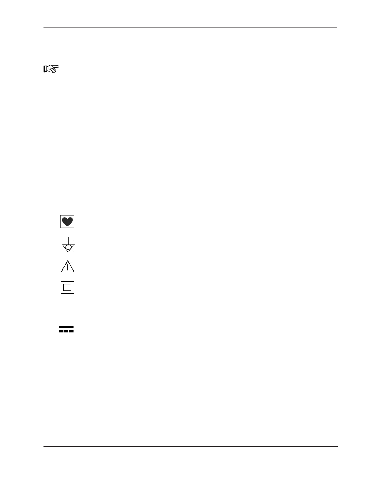
Explanation of the Symbols on the Front and Rear Panel
Protected against electric shock. Type CF equipment per DIN EN 60601-
potential equalisation point for grounding
Caution: Consult accompanying documents
Instrument meets protection class II
~ AC voltage
DC voltage
10
Page 11
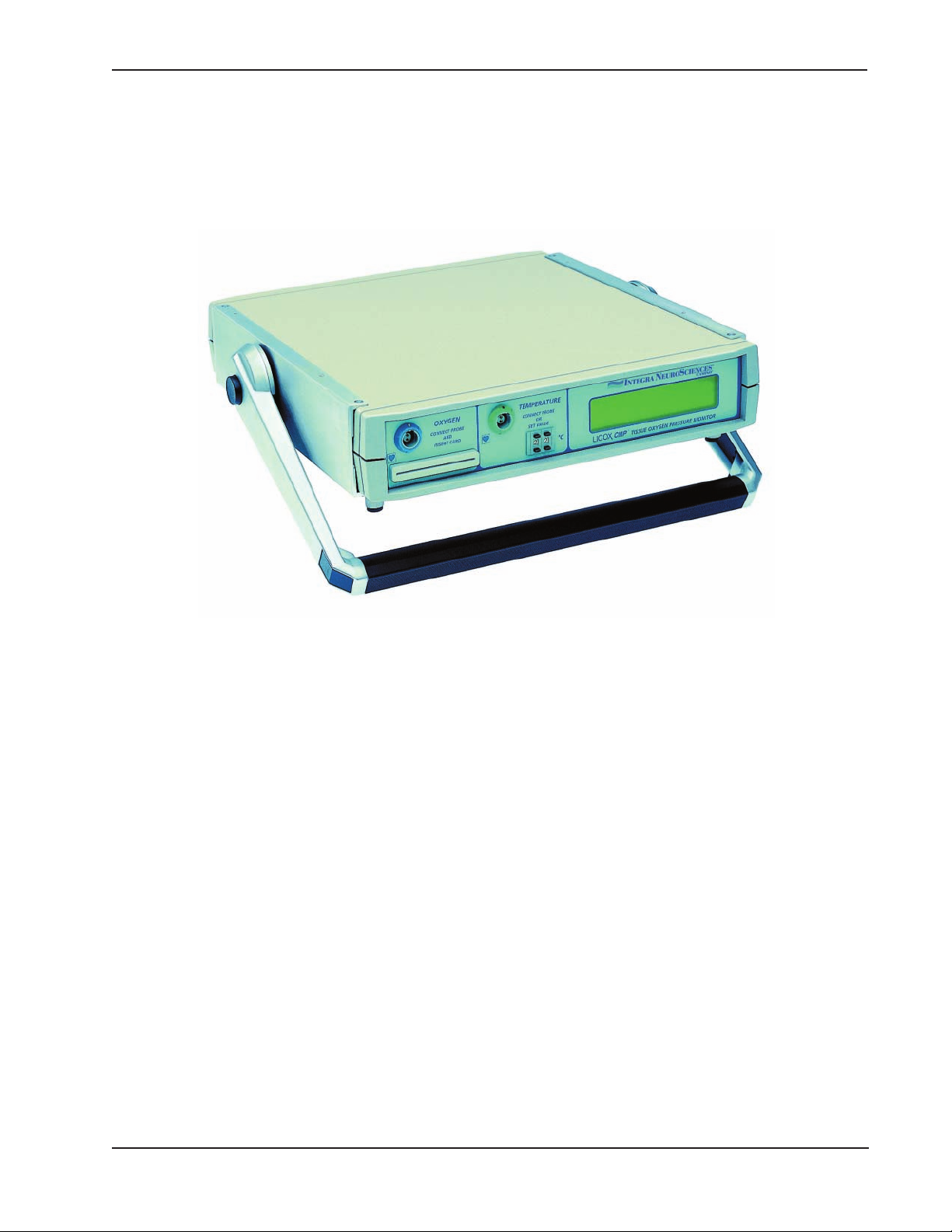
6 Components of the LICOX CMP System
Instruments, Cables and Accessories
Model No. Description
AC3 LICOX CMP instrument
Fig. 3: LICOX CMP Instrument
The following components are delivered with the LICOX CMP instrument (Model No.
AC3.1). Please check that all components are included on delivery.
A10 • LICOX wall connected power supply
BC10PA • pbtO2 probe cable (blue),
the cable is not suitable for sterilization in autoclave
BC10TA • temperature probe cable (green),
the cable is not suitable for sterilization in autoclave
BC10PV • extension cable for pbtO2 probe (blue) , sterilization in autoclave is pos-
sible
BC10TV • extension cable for the temperature probe (green), sterilization in auto-
clave is possible
BC10R • test equipment for the functional test of the device: test resistor for input
circuit and smart card to activate the diagnostic program
BC10S • test plug for the patient saftey test
11
Page 12
Optional accessories used in displaying the measured data with
other monitoring systems
The LICOX monitor link A, model D1 and connection cables are required to display data
obtained with the LICOX CMP instrument on bedside monitors. These cables connect
the analog signal outputs of the LICOX CMP with the analog signal inputs of the patient
monitoring pressure module. Please refer to Directions for Use (DFU) for model LML.1,
D1 for detailed description.
Disposable Catheter Probe and Bolt
The flexible catheter probe is used for monitoring of pbtO2 in tissue and in CSF. The
p
sensor is a closed polarographic cell located at the tip of the completely closed
btO2
polyethylene (PE) catheter body. The p
cylindrical tissue layer located concentrically around the catheter.
There are 2 polarographic electrodes in the polyethylene tube, one made of silver, one
of gold; these are connected to the electrical contact pins in the connector housing. The
cavity of the PE tube is filled with an electrolyte solution buffered at a pH value of 7.4.
The probe no longer functions if the PE tube is torn or cut.
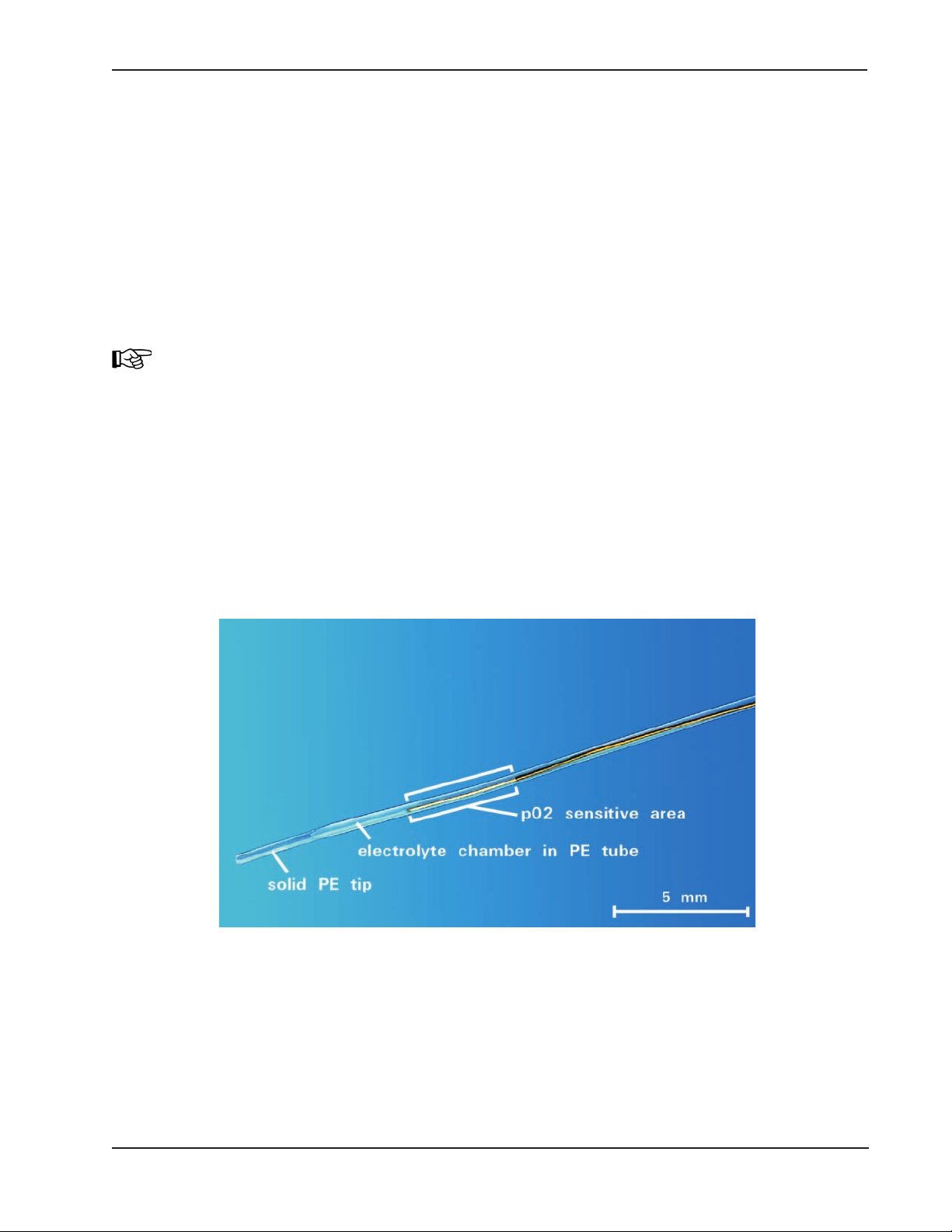
Fig. 4 shows a picture of the probe tip. The solid polyethylene tip, the hollow portion of
the catheter body which is filled with an electrolyte solution, and the p
surface are illustrated.
is determined near the tip of the probe in a
btO2
btO2
sensitive
Fig. 4: Tips of oxygen probe Type CC1.SB
Calibration data is determined during manufacture for each probe and is stored on a
smart card. The smart card is delivered with the sensor.
12
Page 13

The probe is delivered in a waterproof protector tube containing a small volume of an
electrolyte solution (phosphate buffer pH 7.4). The protector tube is closed at one end
and at the other end is sealed at the probe connector housing by a Luer-type fitting.
The probe must be stored in the supplied humid chamber to avoid evaporation of the
electrolyte contents. The protector tube must be removed before use.
Store cool, but do not freeze.
Protect from direct sunlight.
Observe the expiration date.
Storage in refrigerator is recommended, but probe should not be
frozen.
The probe is double-packed and is delivered sterile.
Disposables
Probe type Length of the Distance from ø catheter ø catheter Catheter Cable
sensi- tip to sensitive near the near the length fix-
p
btO2
tive area area tip root mounted
(mm) (mm) (mm) (mm) (mm)
CC1.SB 5 5 0.8 <1.0 150 no
Polarographic data
Gold cathode, silver anode
Polarization voltage 795 mV
Stirring artifact < 4%
Zero current < 1 nA
Temperature coefficient of sensitivity ≈ 4%/°C
Probe type pbtO2 sensitivity at 37 °C Response time T90 at 35 °C
(nA/mmHg pbtO
CC1.SB
≈ 2.8 ≈ 290
2)
(s)
13
Page 14
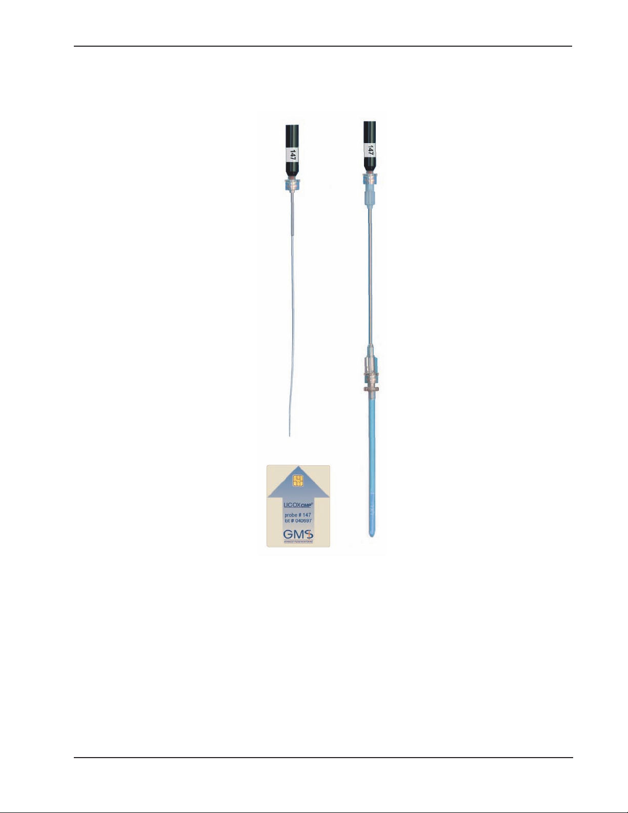
Model No. Description
CC1.SB Probe for intracranial pbtO2 measurement with complete introducer system
IMx.xx
Fig. 5: Probe Type CC1.SB with and without protector tube and smart card
14
Page 15
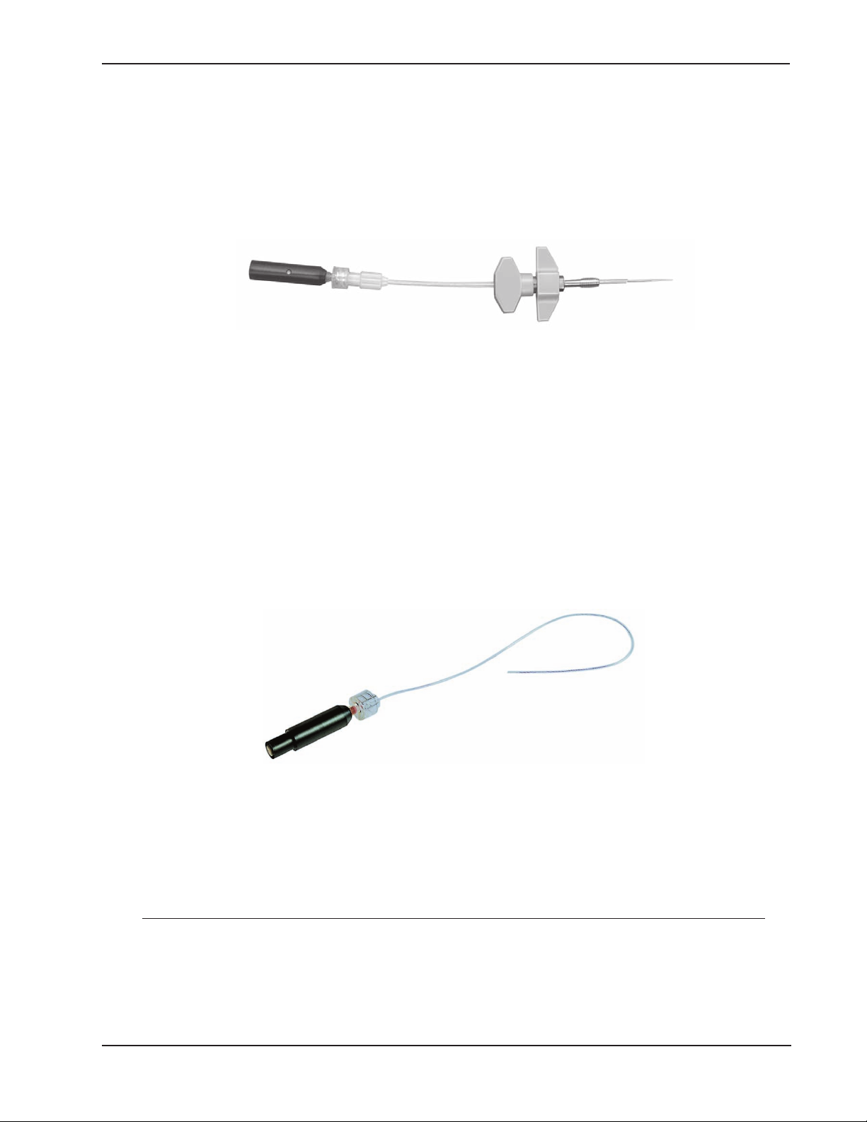
Complete system for intracranial pbtO2 measurement
Model No. Description
IM1.S Complete bolt kit for intracranial p
measurement with one access
btO2
channel; disposable kit with probe CC1.SB, bolt, insertion catheter, drillbit and accessories
Fig. 6: IM1.S measurement kit completely assembled for intracranial measurement
Multi Channel Bolt Kits One, two and three way kits are available, see sales literature.
Temperature catheter microprobes
Thermocouple probes
Thermocouple (type K), Ni/NiCr microwire in polyethylene tube, flexible
C8.B Thermocouple probe for complete bolt kits IMx.xx
Fig. 7: C8.B temperature probe
Probe type Length of the Distance from ø catheter ø catheter Catheter
temperature tip to sensitive near the near the length
sensitive area area tip root
(mm) (mm) (mm) (mm) (mm)
C8.B 3 2 0.8 0.8 126
VK4/VM5 Kit for check of zero display
15
Page 16
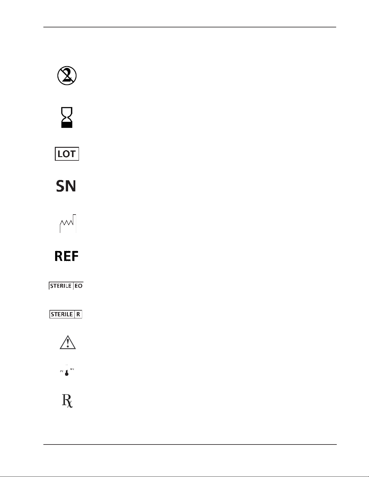
7 Explanation of the Symbols on the Packaging of Sensors
and Accessories
The contents of the package is exclusively intended for single use (disposable).
The year and last date of the month (e.g. 2001-03) in which the product can
be used are indicated next to this symbol. The content of the package can
be used safely up to this date.
The lot number of the package contents is indicated next to this symbol.
This symbol identifies the serial number of the package contents. In oxygen
probes, the serial number corresponds to the "probe number".
The year and month, (e.g. 2001-02), of manufacture of the package contents are indicated next to this symbol.
This symbol identifies the model number of the package contents.
The package contents have been sterilized with ethylene oxide gas.
The package contents have been sterilized by gamma irradiation.
Caution: Consult accompanying documents
This symbol shows the permissible storage temperature.
ONLY
Federal (USA) Law restricts this device to sale by or on the order of a physician.
16
Page 17
8 System Set Up
Assembly
The instrument must be switched off before connecting or disconnecting
the LICOX bus connector (No. 10 of Fig. 9) or the low-voltage power
supply connector (No. 7 of Fig. 9).
Self-locking connectors are used on Licox cables; these connectors must
not be turned. To release or to connect a cable, pull or push the connec
tor without turning it. Hold the connector housing and never pull on the
cable.
1. Connect the low voltage output cable of the LICOX power supply to the
socket (No. 7 of Fig. 9) provided at the rear panel of the LICOX CMP
instrument.
Only use the original LICOX power supply (REF:A10)! Use of an
other power supply could endanger the patient's safety and could
damage the LICOX instrument.
The connection voltage is marked on the base of the power supply
(120 V AC).
2. Connect the blue pbtO2 probe cable (REF: BC10PA) to socket (No. 2
of Fig. 8) on front panel.
3. The potential equalisation plug (No. 12 of Fig. 9) at the rear panel of the
instrument may be connected to the hospital ground system, if avail
able.
Functional Check of the System
The proper assembly and functioning of the instrument and the pbtO2 probe cable can
be checked using the test equipment delivered with them (REF: BC10R). The procedure for this is described in chapter 11.
The proper functioning of the system should be checked annually and whenever appropriate function is in doubt.
Fig. 8: Front Panel of the LICOX CMP Monitor
Fig. 9: Rear Panel of the LICOX CMP Monitor
17
Page 18
Connecting the LICOX CMP to other Devices
The analog signal outputs (No. 8 and No. 9 of Fig. 9) are
provided for connection to the patient bedside monitors via the
LICOX Monitor Link LML.1, D1. Please refer to the Monitor Link
Directions for Use (DFU) for detailed instructions. Connect only
to CF rated equipment.
9 Measuring pbtO
2
Checks Prior to Monitoring
Functionality of the instrument (without probe) may be tested before use. (See Chapter 11.)
The function of the pbtO2 catheter may also be checked before use (see the section in
this chapter entitled Plausibility Check).
Connecting the Probe
Starting the Measurement
Temperature Compensation
Checking the probe:
Only use the probe if its sterile packaging is not open,damaged or broken.
Only use the probe before the expiration date labelled on the package.
Only use the probe if it has been stored correctly.
a Connect the blue probe cable (REF: BC10PA) to the pbtO2 probe input of
the LICOX CMP instrument (No. 2 of Fig. 8) and connect the probe.
Do not discard the probe packaging before the probe smart card has been
removed.
b Switch on the LICOX CMP unit; the switch (No. 6 of Fig. 9) is at the rear panel
of the device.
Fig. 8: Front Panel of the LICOX CMP Monitor
Fig. 9: Rear Panel of the LICOX CMP Monitor
18
Page 19
c Insert the smart card into the card slot (No. 1 of Fig. 8) of the LICOX CMP
instrument until it snaps into position. The metallic contact pads on the card
face downwards. The arrow shows the direction of insertion. Probe calibration
data are stored on the smart card.
d Temperature Compensation:
Alternative 1:
Input patient temperature via the code switch (No. 3 of Fig. 8) in °C ; the
set temperature value then appears on the LCD display (No. 5 of Fig. 8)
and is designated T
. The input temperature may be corrected during
SET
use.
If the tissue temperature is set incorrectly, e.g. 1°C too high, then the pbtO
value is underestimated by approx. 4% and vice versa.
Alternative 2:
A temperature catheter may be connected to the CMP monitor (no. 4 of
Fig. 8). The temperature value measured in this manner will appear on
the LCD display (No. 5 of Fig. 8) as Tmp.
Connect temperature probe cable (REF BC10TA) to socket (No. 4 of
Fig. 8) on front panel. Connect the green probe cable (REF BC10TA) to
the C8.B temperature probe and the CMP monitor if temperature
measurement is desired. Use only LICOX temperature probe C8.B with
the LICOX CMP monitor.
If the temperature is measured with a catheter, the pbtO2 value is only
correctly compensated for temperature when the catheter tip is actually located
in tissue.
After the probe has been implanted, the pbtO2 value to which the tip of the probe is
exposed is displayed. The pbtO2 catheter may be disconnected from the CMP monitor
and connected to another as long as the smart card is also transferred to the second
CMP monitor.
2
The fluid-filled protector tube of the probe should not be discarded if the function of the
probe is to be checked after the measurement.
If the probe is continuously operated for more than 5 days then the
measurement error can exceed the defined limits.
Fig. 8: Front Panel of the LICOX CMP Monitor
Fig. 9: Rear Panel of the LICOX CMP Monitor
19
Page 20
Data Recording
A patient monitor may be used to display and record data. Connection of the LICOX
system to patient monitors is described in Chapter 8.
Plausibility Check
Plausibility check of catheter sensitivity
The sensitivity of the probe can be determined before and after measurement. To perform a check after measurement, blood and tissue must be carefully cleaned from the
probe (with a gauze pad soaked in water) and the probe must be re-inserted into its
humid protection cap.
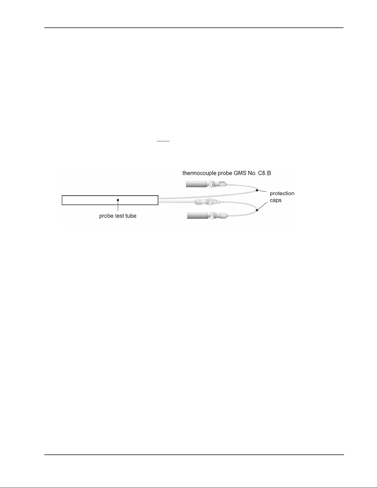
To check the probe, insert it
with its protector tube and a temperature catheter (C8.B)
into the test tube provided with the temperature catheter (a temperature controlled water bath can be used instead of the tube).
Fig. 10: Checking the probe sensitivity
Connect the oxygen probe to the blue probe cable (REF: BC10PA) and the temperature
catheter to the green cable (REF: BC10TA). Turn on the instrument. After a run-in time
of approximately 15 minutes, a pbtO2 value of approximately 150 mmHg should be displayed at sea level and normalized barometric pressure, respectively (altitude zero, 760
mmHg). The exact value expected for the display of pbtO2 in room air saturated 100%
with water vapor (probe in its moist protector tube) depends on the temperature and the
barometric pressure, i.e. the weather and the altitude of the test site above sea level.
20
Page 21
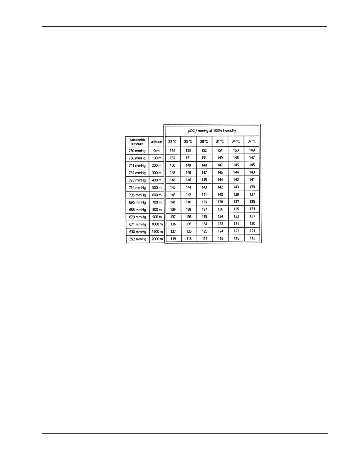
The pbtO2 value in air varies by less than 5%, due to weather. The influence of temperature and barometric pressure on the pbtO2 value in air can be read from the following
table, a 100% water vapor saturation and a reference air pressure of 760 mmHg at sea
level is assumed.
p
of air saturated 100% with water vapor, calculated for various temperatures
btO2
and barometric pressure values or altitudes above sea level, respectively; where
the reference barometric air pressure is assumed to be 760 mmHg at sea level; P
= P0 e
-0.125 h
(Ph = barometric pressure at height, P0 = barometric pressure at sea
level, h = height in km)
h
Checking probe zero after removal from patient
Prior to the zero check, the probe must be carefully cleaned of blood and tissue. The
probe zero displayed is checked in a zero oxygen solution (REF: VK4) that has been
injected into a glass test tube. In the zero solution the expected pbtO2 display is 0 mmHg.
The measured value of 0 mmHg will be displayed approximately 15 minutes after injection of the solution after contaminant oxygen is chemically bound in the zero solution.
(The formula of the zero solution is: One liter deionized and nitrogen saturated water.
16.3 g Na2SO3 dissolved in water as oxygen absorbent together with 2.6 g Na2B4O7 as
accelerator.)
The zero solution is functional for a short period after breaking open the ampule:
• less than 15 min. in a syringe made of plastic material as oxygen is diffuses from the
ambient air through its plastic wall
• approx. 3 h in a glass test tube
21
Page 22

Sensor Implantation Technique
Please refer to Directions for Use (DFU) for Models CC1.SB and C8.B, listed in the
DFUs for bolt kits IM1.S, IM2.S, IM3.ST, and IM1.T.
Troubleshooting
Problems due to instrument malfunction
• Power failure
If the building power supply or the LICOX CMP low-voltage supply is interrupted, the
device restarts automatically after the power supply has been re-established. The
user does not need to restart the instrument or recalibrate.
• Removal of the smart card during measurement
Measurements are interrupted when the smart card is removed. The message please
insert probe card appears on the LCD display (No. 5 of Fig. 1). For the duration of
this message, zero values of measured p
outputs of the CMP monitor. Measurements will continue after the card is re-inserted.
• Electrical disturbances
are transmitted by the analog serial
btO2
Strong electromagnetic disturbances can result in pbtO2 measurement errors. Errors
can continue for a few seconds after the disturbance. These disturbances may occur
when using a high-frequency scalpel or during cardioversion, e.g. during cauterization.
• Damage to cable
If a probe cable (REF: BC10PA and BC10TA) or an extension cable (REF: BC10PV
and BC10TV) is damaged, measured values can be incorrect or the measurement
can be interrupted. The damaged cable must be replaced.
Cables are sometimes damaged when the locking mechanism of the connector is not
operated correctly (never rotate the connector housing; it may only be pulled or
pushed). The cable will break if it is pulled with excessive force when the bayonet is
locked.
If concentrated alcohol is used for cleaning the cable and is applied for more than
approx. 10 seconds, the silicone coating around the cable may be damaged. Moisture can then enter the cable.
• Wet probe and cable connectors
The pbtO2 probe is not waterproof. Do not allow liquids to contact the connector. Do
not dip into liquids.
• Temperature gradient in the housing of the temperature probe connector
The temperature measurement may be inaccurate if the connector of the temperature probe is subjected to significant changes in temperature or if the temperature of
22
Page 23

the connector is beyond the defined range of 18°C to 30°C. This may happen, for
example, during rheumatological cryotherapy or due to direct exposure to strong sunlight. If the probe connector is held with a warm hand, the temperature measurement
may be inaccurate until it is released.
• Device defects
The LICOX CMP instrument displays error messages if it has an internal defect.
Error no. 1 to error no. 3 indicate that a computer component is defective.
Error no. 4 points to a defect in the preamplifiers. If error message no. 4 continues to
be displayed after both probe cables have been removed, then the preamplifier in the
CMP monitor is defective. If error no. 4 is displayed and the cables are attached to
the monitor, then the probe cables are defective or the connector of the cable may be
contaminated or wet. A short occurrence of error no. 4 immediately after connecting
a probe or when using a high frequency (HF) scalpel or an electrocautery device is
normal.
If the probe is touched by cautering forceps and is burned through, the preamplifier of
the monitor can be damaged. The same applies when the probe is cut by an HF
scalpel.
Fault in operation
• Discarding the smart card or use of the wrong smart card
If the smart card is discarded with the probe packaging before use, the probe can not
be used. If the wrong smart card is used with a probe, incorrect measurements result.
• Using the probe longer than the recommended duration of use
If the probe is used continuously for more than 5 days the measurement error could
exceed the defined range.
• Bending the probe
In the tip zone (most distal 6 cm) of a probe, the radius of curvature must not be
smaller than 2 mm. If the probe is bent on itself it is not destroyed but the measurement is interrupted.
• Cutting and tearing
The catheters will no longer function if they are cut or torn.
Risks to the patient
• General risks
The LICOX Brain Oxygen Monitoring System is intended for use by a qualified physician.
The physician should observe sterile technique and general surgical precautions when
penetrating human tissue. Contraindications for needle insertion into the body also
23
Page 24

apply, e.g. considerable coagulopathy and/or susceptibility to infections. A thrombocyte value of less than 50,000 per µl is a clear contraindication.
• Special coagulation problems
In order to avoid hemorrhage in the area of implantation, blood coagulation must be
carefully monitored when measuring in the brain during total body hypothermia, or in
patients in hepatic coma or suffering from other diseases which could impair blood
coagulation.
• Risks of cerebral measurements
When using a bolt kit for intracranial measurement (e.g. REF: IM1), the following
risks to the patient must be considered:
If a drill-bit other than that delivered with the complete intracranial bolt kit is
used, the hole may be too large or too small; the skull bolt will then either not
fit correctly, get stuck half way when turning in a hole that is too small in
diameter, or may even break if excessive force is applied.
Danger of confusing the drill-bits: The LICOX IM1 System is supplied with
a drill-bit 3.8 mm in diameter; the ICP-bolt of Integra NeuroSciences, Camino
Model 110-4B has a drillbit 2.7 mm in diameter. Use the drill-bit supplied
with the LICOX device.
Before drilling, the drill-stop must be correctly positioned on the bit taking into
account the thickness of the skull. The tip of the drill-bit should penetrate the
inner table by not more than 1 mm. Use a hand operated drill only. Do not use
drills driven by compressed air.
If the dura mater is not incised (with a small cutting instrument) before the stylette is advanced,
the dura mater could be pulled away from the skull, possibly resulting in hemorrhage.
The drill hole must not be made too near to the sagittal line, to avoid hitting
the superior sagittal sinus, a parasinoidal sinus or the stem area of superior
cerebral veins. Even taking this into account, a risk of hemorrhage remains.
Before drilling, always ensure that neurosurgical treatment and a CT scanner
are available in case of severe bleeding at the twist drill hole.
In general, there is a risk of infection due to use of intracranial catheter
instruments. It is recommended that LICOX probes not be left in tissue for
more than 5 days.
To avoid infection, the introducer must be sealed. If the seal is not made,
cerebrospinal fluid may appear within the outer tube of the introducer. The
seal should be tightened immediately if cerebrospinal fluid begins to enter
the introducer tube.
24
Page 25

Artifact
• Movement artifact
Extreme acceleration of the probe tip (e.g. during continual knocking of the catheter
tip on the edge of a table) results in an increased signal of usually not more than 15%.
• Run-in drift
After implantation of a probe it takes 1 - 2 minutes before the local pbtO2 is correctly
displayed. However, due to the microtrauma of implantation, the initial pbtO2 values
displayed may not represent the pbtO2 of the surrounding tissue.
After implantation, the run-in time (time until the pbtO2 values are representative of
the surrounding region of the brain) may be as long as 2 hours.
• Hemorrhage due to probe implantation
In rare cases, e.g. if a vessel is punctured during implantation or when coagulation is
insufficient, hemorrhage can occur. The measured pbtO2 values are generally above
the tissue values for the duration of bleeding. After the bleeding has stopped, the
pbtO2 indicated is normally below it's value in surrounding non-affected tissue if the
blood infiltration surrounding the puncture is thicker than approximately 100 µm.
• Bypass for cerebrospinal fluid
If a patient has enlarged or shifted cerebral ventricles the probe or its introducer may
puncture the lateral ventricle when inserted (the probe tip reaches approximately 35
mm below the dura level). If this occurs, the probe will create a channel that directly
connects the inner ventricular system with the subarachnoid space, bypassing the
natural pathways. Because of the pressure difference between the lateral ventricle
and the subarachnoid space, it is possible that cerebrospinal fluid (CSF) from the
ventricle could flow along the probe. The measured value then would correspond to
the oxygen partial pressure of the CSF and is not representative of the surrounding
tissue.
• Displacement
The actual position of the sensor must be considered for interpretation of data. It is
always possible that the sensor has displaced from the intended location.
• Halothane Sensitivity
Halothane affects the measured values of polarographic pbtO2 probes; including the
LICOX probe. Under the influence of halothane, the pbtO2 measurements are overestimated. Other anesthetic gases such as nitrous oxide (N2O), enflurane and
isoflurane can be used without impairing the accuracy of the measurement.
25
Page 26

10 Cleaning, Disinfection, Sterilization and Disposal
Do not allow cleaning liquid to enter the smart card slot of the instrument or
into connectors of the cables and/or the LICOX CMP instrument .
The power supply will be destroyed if liquid enters into it’s housing. Immediately
discontinue use of this power supply even if it is apparently unaffected.
Do not use a cable when its socket is damp, e.g. shortly after sterilization.
The Instrument
The LICOX CMP instrument may be cleaned with a towel that has been dampened with
an aqueous soap solution which may also contain formaldehyde. Diluted alcohol-based
disinfectant solutions may also be applied. Solvents containing phenol should not be
used.
The Cables
Blood and tissue remains may be removed from the cables with a towel that has been
dampened with an aqueous soap solution which may also contain formaldehyde. Disinfectants containing a high percentage of alcohol or phenol will damage the cables.
The extension cables (REF: BC10TV) for the temperature probe and for the oxygen
probe (REF: BC10PV), can be sterilized in an autoclave (121°C, max. 3 bar, 20 min).
Extension cables may not be sterilized by EtO or other methods.
The probe cables (REF: BC10PA and BC10TA), cannot be sterilized in an autoclave.
Cleaning contaminated cable sockets and connectors:
If salt solutions, blood or other body fluid enter the cable connectors or sockets, then the
following cleaning procedure may be followed: The contaminated area of the connector
may be rinsed with distilled water until all salty remains and blood contamination have
been removed. A small brush can be used for this purpose (e.g. a large clean toothbrush). After blowing out the water, the connector (not the cable itself) may be immersed
for approximately 5 seconds in ethanol (or isopropanol). Finally, the remaining alcohol
must be blown out of the connector. The cleaning procedure may be repeated if required. After cleaning, the cable must dry for several hours.
26
Page 27

Probes and Other Disposables
Probes and other disposables of the LICOX system are for single use
only. This applies to all parts of the LICOX system whose model number
begins with the letters C, V or I; this applies to the oxygen probe, (REF:
CC1.SB) and the temperature probe (REF: C8.B) as well as the
components of the complete bolt kit used for intracranial measurement
IM1, etc.
Probes can not be resterilized.
Disposal of Probes and Disposable Accessories
Prior to disposal, any probe and other disposables which have been contaminated with
blood, body fluid or tissue must be effectively disinfected.
The plastic parts of the disposable probes consist mainly of polyethylene or polyacetate.
None of the articles contain PVC.
Other synthetic materials (Telura/Novodur, polyimide, nylon, PTFE, silicone rubber) are
only present in small amounts.
The packaging is made of paper, polypropylene, polycarbonate and polyethylene.
The metals used are steel, stainless spring steel, other stainless steels and copper as
well as extremely small amounts of gold, silver and nickel in microwires and coatings.
Risks associated with disposal of LICOX CMP monitor, cable and accessories
The LICOX CMP device and accessories should be cleaned before disposal if contaminated with blood or tissue. The act of disposing of the LICOX CMP device and accessories poses no known risks. The LICOX CMP device and accessories may be returned to
Integra Neuro Sciences for disposal if desired.
27
Page 28
11 Maintenance
Provided that the hospital biomedical department has the equipment and knowledge to
perform the instrument safety tests, the LICOX CMP instrument does not require periodical maintenance by the manufacturer.
The user should carry out the following checks at regular intervals as well as whenever
there are doubts concerning the accurate function or the safety of the instrument.
Periodic Checks to be Carried Out by the User
Checking the pO2 measurement:
Interval:
Once per year and as necessary
Checking the sensitivity of the CMP monitor:
Insert the test smart card #1 (part of the test set REF BC10R), into the card slot (No.
1 of Fig. 8). Connect the dummy-probe standard resistor (part of the test set REF
BC10R) to the probe connector of the blue pbtO2 probe cable.
Disconnect any temperature probe from the green temperature probe cable. The temperature display must show the T
Expected values on the display:pO2: 154.6mmHg
If the instrument is working correctly, a pbtO2 value of 154.6 mmHg is now displayed on
the LCD. If a value between 154.2 and 155.0 mmHg is displayed then the accuracy
specifications of the unit are met. If values deviating from the aforementioned values are
displayed, the instrument must be returned for re-calibration or repair.
indicator. Set code switch (No. 3 of Fig. 8) to 22°C.
SET
T
: 22°C
SET
Checking the zero pressure calibration of the CMP monitor:
After completing the previous test, disconnect the Dummy-Probe standard resistor
from the blue pbtO2 probe cable. Leave the test smart card in its slot.
Expected values on the display:pO2: 0.0 mmHg
T
: 22°C
SET
If the zero current is correctly adjusted a pO2 value of 0.0 mmHg must be displayed on
the LCD display. If any other value is displayed, the instrument must be returned for recalibration or repair.
Fig. 8: Front Panel of the LICOX CMP Monitor
Fig. 9: Rear Panel of the LICOX CMP Monitor
28
Page 29

Checking the temperature measurement
Interval:
Once per year and as necessary
Procedure:
Perform system set up as for a pbtO2 measurement using any probe smart card; the
oxygen probe does not need to be connected for this test. Connect a temperature
probe (REF C8.B); a temperature value labeled as T
To test the temperature measurement, place the probe in a water bath inside a Dewar
vessel with closed lid. Use at least two temperatures between 20°C and 45°C for the
test. A calibrated precision thermometer with an absolute error below 0.05°C should be
used as the reference instrument. Use at least 3 temperature probes, one for each of
three separate tests.
Allow a warm up period of at least 30 minutes after the CMP monitor has been turned on
and a temperature probe connected. Ensure that the probe connector is maintained at a
temperature of between 18° and 30°C during the test. Ensure that the connector temperature remains constant for the duration of the test.
If the difference between the reference instrument display and the LICOX instrument
display is less than 0.2°C, the LICOX CMP is working correctly within the limits of its
defined accuracy. If different temperature values are displayed, the LICOX CMP instrument must be re-calibrated by the manufacturer.
will be displayed.
mp
Safety checks performed by the biomedical department of the
hospital
The check includes the test of the maximum leakage current values according to
IEC 601-1 CF (DIN EN 60601-1 CF).
Interval:
Once per year
Procedure:
Connect the test plug (REF BC10S) to the blue and green input sockets of the LICOX
CMP device (No. 2 and No. 4 of Fig. 8) prior to the determination of the leakage currents. If this test plug is not used then the input amplifiers could be destroyed!
The measurements should yield the following results:
• device leakage current (IEC 601-1, subclause 19.4.f): < 10 µA
• patient leakage current (IEC 601-1, subclause 19.4.h): < 10 µA
• patient leakage current with main voltage on the F-type
isolated applied part (IEC 601-1, subclause 19.4.h.2): < 10 µA
Should the measured values exceed these limits the instrument must not be
used. The instrument must be returned for repair.
The patient safety test must be concluded with a complete functional test to avoid any
problems that might occur during the test procedure.
29
Page 30

12 Technical Specifications
LICOX CMP Instrument
Instrument type:
• LICOX CMP
Principle:
• pbtO2 measurement: polarographic electrochemical sensor
• Temperature measurement: Type K thermocouple
• Displayed values update rate: once per second
Preamplifier:
• For pbtO2 probe: current amplifier, input 0 - 5000 nA, resolution 0.2 nA
• For temperature probe: voltage amplifier, input 0 - 4 mV, resolution 4 µV
Outputs:
LICOX CMP, type AC3 master instrument:
• Analog outputs: 0 -10 V, smallest increment 0.24 mV, 150 W impedance
• Connectors for both pbtO2 and temperature signals
• Resolution: 10 mV/mmHg for pbtO2 (10V = 1000 mmHg)
100 mV/°C for temperature signal (10V = 100 °C)
Display:
Alphanumeric LCD
• pbtO2: 0.0 - 1999 mmHg
• Temperature: 0.0 - 99.9 °C
• Text to explain operation and parameters used
Calibration:
Calibration data for the pbtO2 sensor is provided to the LICOX CMP instrument via a
smart card. Temperature probes are tested/selected during manufacture by comparison to reference temperature values. The pbtO2 and temperature channels of the CMP
monitor are calibrated during it’s manufacture.
Accuracy in Long-term Operation:
Accuracy determined during continuous pbtO2 measurement at 37°C:
• pbtO2 0–20mm Hg ± 2mmHg
• pbtO2 20–50mm Hg ± 10%
• pbtO2 50–150mm Hg ± 12%
• Temperature ± 0.2°C
• Duration of Use: 5 days maximum
• Duration of Use: 5 days maximum
30
Page 31

Power supply / Power Consumption:
Use only original LICOX CMP power supply (REF:A10)
Power supply output:7.5 VDC, 1.7 A
Building power supply output: 120 V AC, 50 - 60 Hz
Main Fuse:
500 mA, slow-blow-fuse
Protection against electrical shock:
Class II, Type CF applied parts: pO2 catheter, temperature catheter
Protection against harmful ingress of water:
ordinary
Degree of safety in the presence of flammable anesthetics mixture with air or with
oxygen or nitrous oxide:
not suitable for use in the presence of flammable anesthetic mixture with air or with
oxygen or nitrous oxide
Mode of operation:
continuous
Operating Limits:
temperature: +10 to 40°C
pressure: 700hPa to 1060 hPa
humidity: 30% to 75% RH non condensing
Shipping/storage Limits:
temperature: 0 to +50°C
pressure: 500hPa to 1060 hPa
humidity: 0% to 95% RH non condensing
Dimensions and Weight:
34 cm (breadth) x 32 cm (width) x 8.5 cm (height), 4200 g (net weight)
Language:
English
31
Page 32

Appendix
Abbreviations
CPP Cerebral Perfusion Pressure
CSF Cerebrospinal Fluid
HP Hewlett Packard
ICP Intracranial Pressure
ICU Intensive Care Unit
LCD Liquid Crystal Display
OR Operation Room
p
btO2
Brain Tissue Oxygen Partial Pressure
32
Page 33

Terms of Sale
Pricing:
Prices stated in specific written quotations are firm for thirty days from the date given, and are otherwise subject to
change without prior notice. Pricing terms stated on written agreements are governed by such agreements.
Minimum Order Requirements:
Minimum order requirement is $100 (a $10 handling charge will be added to any order under $100). For partial case
orders, contact the Customer Service Department for quotation.
Shipments:
F.O.B. INTEGRA NEUROSCIENCES point of shipment within the continental United States. Shipping costs (including
freight and insurance) shall be prepaid by INTEGRA NEUROSCIENCES and invoiced to Customers.
Ordering Procedure:
A written purchase order on Customer’s form may be requested for purchases of INTEGRA NEUROSCIENCES products,
but no terms set forth in a purchase order of Customer shall be binding on INTEGRA NEUROSCIENCES other than the
terms that specify the product name, quantity and shipping.
Acceptance of Orders:
Orders are accepted upon approval by INTEGRA NEUROSCIENCES in Plainsboro, New Jersey.
Return Policy:
• Authorization number must be obtained prior to returning product.
• Sterile product must be returned in unopened, undamaged cartons, packed to prevent damage.
• Non-sterile product must be returned in unused salable condition.
• Custom or special order products will not be accepted for credit.
• Credit will be issued subject to the following:
a) Goods returned prior to 3 months from ship date…20% restocking charge.
b) Goods returned between 3 and 6 months of ship date…50% restocking charge.
c) Goods will not be accepted for credit after 6 months.
Customer Service Department:
INTEGRA NEUROSCIENCES
311 Enterprise Drive
Plainsboro, New Jersey 08536
(800) 997-4868 (USA/Canada)
(800) 654-2873 (USA/Canada)
(609) 275-0500 (Outside USA)
(609) 275-5363 (FAX)
33
Page 34

Integra NeuroSciences Limited Warranty
INTEGRA NEUROSCIENCES warrants that each new INTEGRA NEUROSCIENCES product is free from defects in
material and workmanship under normal use and service for a period of two (2) years (except as otherwise expressly
provided as to accessory items) from the date of delivery by INTEGRA NEUROSCIENCES to the first purchaser, but not
beyond the “Expiration” date stated on any product labeling. Surgical instruments are guaranteed to be free from defects
in material and workmanship when used normally for their intended purpose. Any covered product which is placed by
INTEGRA NEUROSCIENCES under a lease, rental or installment purchase agreement and which requires repair service
during the term of such placement agreement shall be repaired in accordance with the terms of such agreement. If any
such defect occurs during the warranty period or term of such placement agreement, the purchaser should communicate
directly with the INTEGRA NEUROSCIENCES home office. If returned to INTEGRA NEUROSCIENCES at its home
office, repair or replacement will be carried out at INTEGRA NEUROSCIENCES’s sole discretion, at INTEGRA
NEUROSCIENCES’s expense, subject to the terms of this warranty and applicable agreements. The defective product
should be returned promptly, properly packaged and postage prepaid. Loss or damage in return shipment to INTEGRA
NEUROSCIENCES shall be at CUSTOMER’s risk.
IN NO EVENT SHALL INTEGRA NEUROSCIENCES BE LIABLE FOR ANY LOSS OF USE, REVENUE OR PROFIT OR
FOR ANY INCIDENTAL, EXEMPLARY, INDIRECT, CONSEQUENTIAL OR SPECIAL DAMAGES, WHETHER ARISING
IN CONTRACT OR IN TORT, IN CONNECTION WITH THE ACQUISITION OR USE OF ANY INTEGRA
NEUROSCIENCES PRODUCT. Further, this warranty shall not apply to, and INTEGRA NEUROSCIENCES shall not be
responsible for, any loss or damages arising in connection with the purchase or use of any INTEGRA NEUROSCIENCES
product which has been repaired by anyone other than an authorized INTEGRA NEUROSCIENCES service
representative or which has been repaired or serviced using materials or parts provided, modified or designed by anyone
other than INTEGRA NEUROSCIENCES or its authorized representatives, or which has been, altered in any way so as,
in INTEGRA NEUROSCIENCES ’s judgment, to affect its stability or reliability, or which has been subject to misuse,
negligence or accident, or which has been subject to improper or negligent installation or storage, or which has been
subject to improper cleaning, sterilization or maintenance, or which has been subject to accidental damage arising from
acts of God, electrical power damage, equipment malfunction, unusual stress, unreasonable operating procedures or
abnormal or extreme operating conditions, or which has been used otherwise than in accordance with the instructions
furnished by INTEGRA NEUROSCIENCES.
INTEGRA NEUROSCIENCES DISCLAIMS ALL OTHER WARRANTIES, EXPRESS OR IMPLIED, WRITTEN OR ORAL,
INCLUDING BUT NOT LIMITED TO ANY IMPLIED WARRANTY OF MERCHANTABILITY OR OF FITNESS FOR A
PARTICULAR PURPOSE OR APPLICATION OR WARRANTY OF QUALITY, OTHER THAN THOSE EXPRESSLY SET
FORTH IN THE PRODUCT LABELING. INTEGRA NEUROSCIENCES neither assumes nor authorizes any
representative or other person to assume for it any other liability in connection with INTEGRA NEUROSCIENCES
products.
____________________________________
LICOX CMP Manual USA
Revision 03_US / 01_2004
2004-05-01
LICOX CMP Manual 03_US 1_2004.pmd
45136 Rev. C
34
 Loading...