


 Loading...
Multi-Parameter Monitor
Model MPM-1 Technical Manual

Multi-Parameter Monitor
Model MPM-1
Technical Manual
1 |
Introduction |
|
|
|
1.1 |
Disclaimer and Warnings......................................................................... |
1-2 |
|
1.2 |
System Overview..................................................................................... |
1-4 |
|
1.3 |
Technical Specifications .......................................................................... |
1-7 |
|
1.4 |
Limited Warranty................................................................................... |
1-10 |
|
1.5 |
Contact Information ............................................................................... |
1-11 |
2 |
Operation |
|
|
|
2.1 |
General Operation.................................................................................... |
2-2 |
|
2.2 |
Principles of Operation ............................................................................ |
2-9 |
3 |
Testing and Preventive Maintenance |
|
|
|
3.1 |
Operational Testing.................................................................................. |
3-2 |
|
3.2 |
Battery Replacement.............................................................................. |
3-26 |
|
3.3 |
Bedside Monitor Calibration.................................................................. |
3-27 |
4 |
Troubleshooting |
|
|
|
4.1 |
Introduction.............................................................................................. |
4-2 |
|
4.2 |
Power Supply Malfunctions..................................................................... |
4-3 |
|
4.3 |
LCD Malfunctions ................................................................................... |
4-4 |
|
4.4 |
Error Messages......................................................................................... |
4-5 |
|
4.5 |
Cabling and Interfacing Problems ........................................................... |
4-7 |
5 |
Technical Notes |
|
|
40201–C |
MPM-1 Technical Manual |

1 Introduction
1.1 |
Disclaimer and Warnings |
..................................................................................... 1-2 |
1.2 |
System Overview................................................................................................. |
1-4 |
1.3 |
Technical Specifications ...................................................................................... |
1-7 |
1.4 |
Limited Warranty............................................................................................... |
1-10 |
1.5 |
Contact Information ........................................................................................... |
1-11 |
40201–C |
1-1 |
MPM-1 Technical Manual |

1.1 Disclaimer and Warnings
PROPRIETARY INFORMATION
INFORMATION CONTAINED IN THIS TECHNICAL MANUAL IS PROPRIETARY TO INTEGRA NEUROSCIENCES AND MAY BE USED ONLY FOR THE PURPOSE OF PERFORMING OPERATIONAL CHECKS. THE PURCHASE OR POSSESSION OF THIS MANUAL DOES NOT CONFER, TRANSFER OR LICENSE ANY OTHER RIGHTS TO THIS INFORMATION. ANY OTHER USE OR DISCLOSURE AND/OR REPRODUCTION (BY ANY METHOD) OF THE INFORMATION CONTAINED HEREIN IS STRICTLY PROHIBITED UNLESS WRITTEN PERMISSION IS OBTAINED FROM INTEGRA NEUROSCIENCES.
AUTHORIZED SERVICE
This manual is intended for use by biomedical personnel to perform operational checks. Any adjustments or procedures that exceed the scope of this manual should be referred to Integra NeuroSciences.
Integra NeuroSciences does not condone or approve of service activity on its products by anyone other than Integra NeuroSciences personnel; and Integra NeuroSciences is not responsible for any unauthorized repairs.
DEFINITION OF DANGER, CAUTION AND NOTE
Danger – means there is the possibility of injury or death to you or others. Caution – means there is the possibility of damage to the unit or other property.
Note – indicates points of particular interest for more efficient and convenient operation.
SAFETY CONSIDERATIONS
Danger – Risk of explosion if used in the presence of flammable anesthetics.
Caution – Do not autoclave or immerse the MPM-1 as damage may occur. If the MPM-1 is exposed to liquids, turn off the unit, remove the power cord and thoroughly dry the unit before reapplying power.
Caution – Do not use solvents or cleaning agents as they could damage the plastic exterior of the MPM-1.
Caution – To reduce the risk of electric shock do not remove the cover. Refer servicing to qualified personnel.
Caution – Read Directions for Use before connecting to bedside patient monitors.
Caution – Grounding reliability can only be achieved when connected to Hospital Grade Receptacle.
Caution – Where the integrity of the external PROTECTIVE EARTH CONDUCTOR arrangement is in doubt, the equipment shall be operated from its internal electrical power source (battery).
40201–C |
1-2 |
MPM-1 Technical Manual |

Caution – This equipment should not be used with high frequency surgical equipment.
Caution – Integra NeuroSciences Catheters are for single use only. Do not attempt to re-sterilize or reuse. Integra NeuroSciences cannot assume any responsibility for damage caused by re-sterilized Catheters. Used catheters should be considered as a potential biohazard. Follow all established laws and regulations pertaining to the handling and disposal of biohazardous materials.
Caution – The MPM-1 contains Static Sensitive Devices. Observe proper ESD precautions when working with Static Sensitive Devices.
SHIPPING INSTRUCTIONS
A shipping container is available. To insure proper preparation and shipping, contact Integra NeuroSciences for instructions.
APPLICABILITY
This Technical Manual is applicable to the Multi-Parameter Monitor with waveform display, Model MPM-1. Contact Integra NeuroSciences for information for equipment not covered in this manual.
Integra NeuroSciences reserves the right to change specifications and procedures without notice.
40201–C |
1-3 |
MPM-1 Technical Manual |
1.2 System Overview
1 |
6 |
1 |
6 |
|
|||
2 |
|
|
|
3 |
7 |
2 |
7 |
|
|
||
|
|
3 |
|
4 |
8 |
4 |
8 |
|
|
5 |
9 |
9 |
|
5 |
|
|
10 |
10 |
|
11 |
|
|
11 |
|
|
|
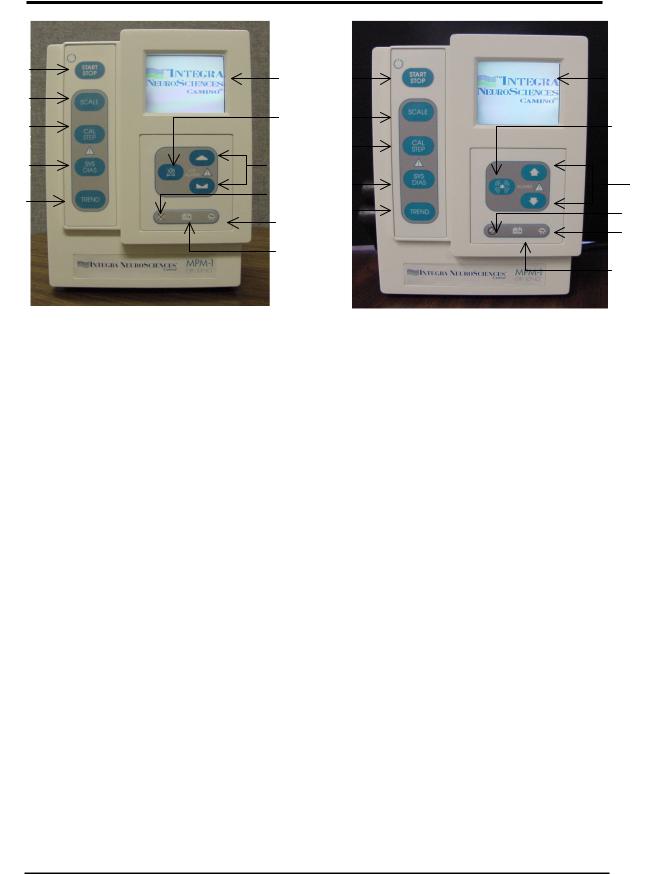
Figure 1-1 International Front Panel |
Figure 1-2 Domestic Front Panel |
1.START/STOP – Press to turn MPM-1 on or off.
2.SCALE – Press to change scale of pressure waveform on MPM-1 Display.
3.CAL STEP - Used to calibrate or check correlation of external bedside monitor.
4.SYS/DIAS – Press to toggle between the CPP-ICP-ICT display and the SYSTOLIC-ICP-DIASTOLIC display.
5.TREND – Press to graphically display the last 12 or 24 hours of ICP and/or CPP values.
6.LCD DISPLAY – Displays ICP waveform, numerical values and trend data.
7.SILENCE ALARM – Press to silence the alarm for 3 minutes.
8.UP and DOWN – Press the button(s) to set the desired alarm limit value.
9.ALARM DISABLED INDICATOR – Illuminates whenever the ICP alarm limit is set to OFF. Flashes when alarm is temporarily silenced.
10.AC POWER INDICATOR - Illuminates when MPM-1 is connected to ~AC power. The battery will charge whenever this indicator is illuminated.
11.LOW BATTERY INDICATOR – Illuminates when MPM-1 is operating on Battery power and less than fifteen minutes battery life remains.
40201–C |
1-4 |
MPM-1 Technical Manual |
12
13
|
14 |
|
15 |
|
16 |
|
17 |
19 |
18 |
|
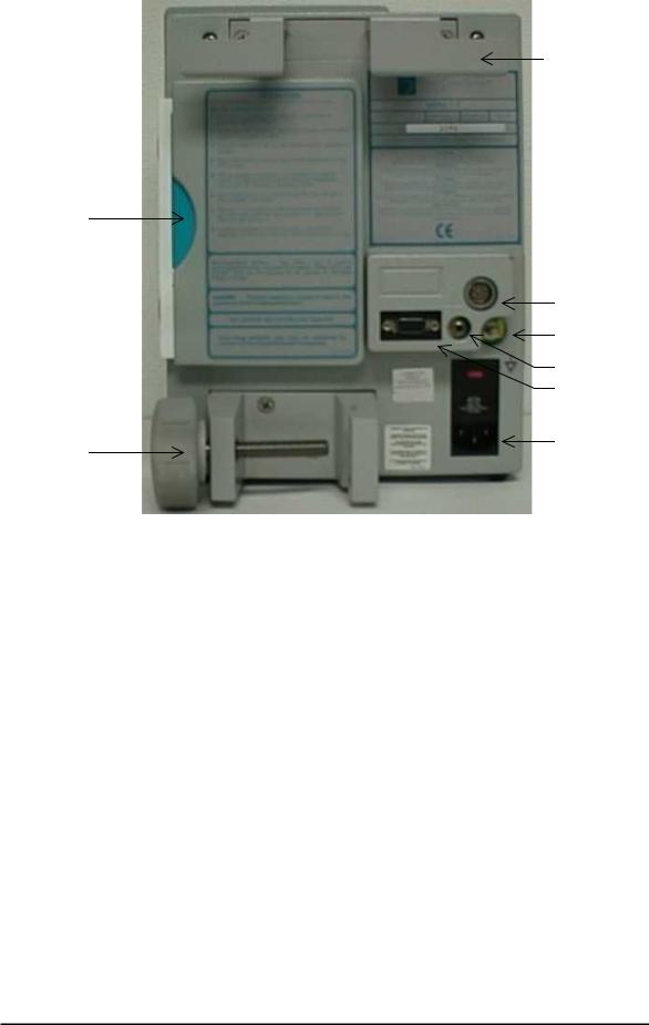
Figure 1-3 Rear Panel
12.COMBINATION CORD WRAP, HANDLE, and BED RAIL MOUNT
13.DFU POCKET – Storage location for the Directions for Use booklet.
14.BEDSIDE MONITOR CONNECTOR – Used for connection to the bedside monitor.
15.EQUIPOTENTIAL CONNECTOR – Used as the connection point for equipotential systems.
16.ICP ISOLATED ANALOG CONNECTOR – Used for data acquisition needs. Provides 1V/100 mmHg output suitable for computer ADC’s or a strip chart recorder.
17.RS232 CONNECTOR – Used for data acquisition needs. Please contact Integra NeuroSciences for details on use of this digital data.
18.AC CONNECTOR – Attachment point for the ~AC power cord. Automatically selects input ~AC voltage of 100, 115 or 230 Volts. Must be plugged into an AC source whenever it is desired to maintain a charge on the internal battery.
19.POLE CLAMP – Used to secure the MPM-1 to an equipment pole.
40201–C |
1-5 |
MPM-1 Technical Manual |
20a |
20c |
20b
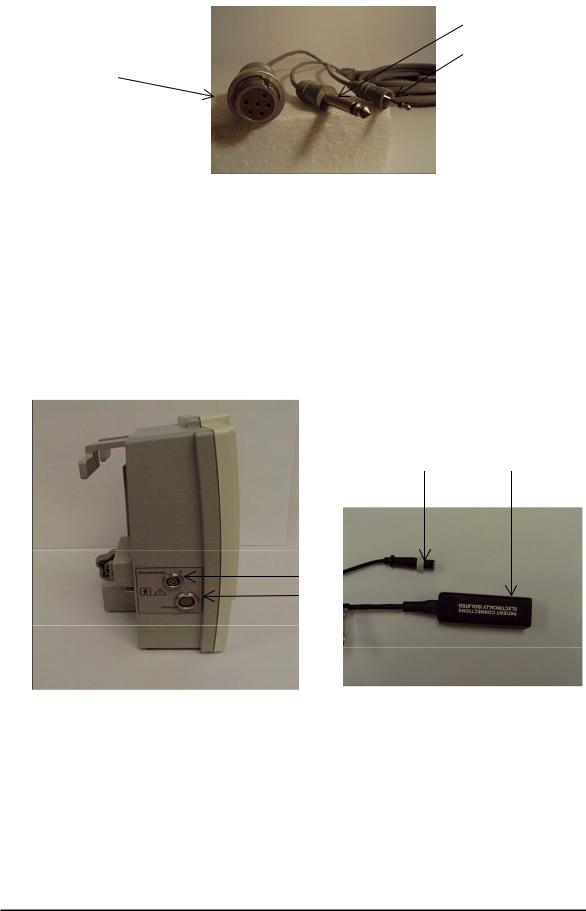
Figure 1-4 Bedside Monitor Cable
20.BEDSIDE MONITOR CONNECTOR – Used for connection to the bedside monitor.
20a. ICT data to Bedside Monitor (Standard Phone Plug)
20b. ICP Waveform to Bedside Monitor (6-Pin Cannon Connector) 20c. Arterial Pressure Data to MPM-1 (Miniature Phone Plug)
22a 21a
22
21
|
Figure 1-5 ICP & ICT Connectors |
Figure 1-6 Preamp Cable |
21. |
ICP CONNECTION – Attachment point for the Preamp Cable Connector. |
|
|
21.a ICP Catheter to Preamp connection. |
|
22. |
TEMPERATURE CONNECTION – Attachment point for the Temperature Cable |
|
|
Connector. |
|
22.a ICT Catheter temperature connection.
40201–C |
1-6 |
MPM-1 Technical Manual |

1.3 Technical Specifications |
|
INTRACRANIAL PRESSURE (ICP) |
|
Sensor Type: |
Fiber-optic pressure transducer |
Range: |
-10 to +250 mmHg |
Resolution: |
1mmHg for LCD display |
|
0.125 mmHg for Patient Monitoring Systems |
Linearity: |
See individual catheter specifications. |
Hysteresis: |
See individual catheter specifications. |
Freq. Response: |
120 Hz nominal, 100 Hz minimum (3dB down) |
|
1.32 mSec for analog output |
Accuracy: |
± 1 mmHg |
Reference Pressure: |
Atmospheric |
INTRACRANIAL TEMPERATURE (ICT) |
|
Sensor Type: |
Thermistor transducer |
Display Range: |
16.7°C to 42.2°C (65°F to 108°F) |
Accuracy: |
± 0.3°C (0.5°F) [30ºC - 40ºC] |
MEAN CEREBRAL PERFUSION PRESSURE (CPP)
Type: |
Calculated |
Range: |
0 to 200 mmHg |
Resolution: |
1 mmHg |
Accuracy: |
± 1 mmHg |
ALARMS |
|
Audible: |
2kHz ± 1kHz signal, ON 0.5 seconds and OFF 0.5 seconds |
|
at full amplitude |
High ICP Alarm: |
0 to 250 mmHg, 1 mmHg increments |
Low CPP Alarm: |
0 to 150 mmHg, 1 mmHg increments |
Alarm Silence: |
3 minutes |
40201–C |
1-7 |
MPM-1 Technical Manual |

MONITOR INPUTS
“Trapezoidal” pre-amplifier input connection for Integra NeuroSciences ICP catheters
Isolated 3-wire thermistor based TDC input for Integra NeuroSciences ICP/ICT catheters.
Isolated Arterial Pressure (AP) for bed side patient monitoring systems. (1V/100 mmHg)
MONITOR OUTPUTS
Analog ICP for patient monitoring systems. (5µV/V/mmHg) (6-Pin CANNON WK-6 connector)
Analog ICT for patient monitoring systems. (Standard 3-wire YSI 400 interface) (Switchcraft ¼” Plug connector)
Analog ICP for data recording. (1V/100 mmHg) (Switchcraft Model 750 connector)
RS-232 Serial data port. Contact Integra NeuroSciences for details. (9 pin DB9 male connector)
DISPLAY |
|
Type: |
Backlit TFT active matrix LCD panel |
Parameters displayed: |
Pressure Waveform |
|
CPP, ICP, ICT (Main Screen) |
|
Systolic, ICP, Diastolic (Systolic/Diastolic Screen) |
|
12 and 24 hour Trend Information (ICP and CPP) |
BATTERY |
|
Type: |
Rechargeable, sealed lead acid |
Charge Time: |
8-10 hours to full charge |
Operation Time: |
1-2 hour from full charge |
POWER REQUIREMENTS
100-230 V, 50/60 Hz, 50 VA
MONITOR OPERATING LIMITS
Temperature: |
15°C to 40°C (59°F to 104°F) |
Pressure: |
700 hPa to 1060 hPa (20.67 inHg to 31.30 inHg) |
Humidity: |
20% to 95% RH |
40201–C |
1-8 |
MPM-1 Technical Manual |
SHIPPING/STORAGE LIMITS |
|
|
Temperature: |
0°C to 50°C (32°F to 122°F) |
|
Pressure: |
500 hPa to 1060 hPa (14.76 inHg to 31.30 inHg) |
|
Humidity: |
20% RH to 95% RH non-condensing |
|
PHYSICAL DIMENSIONS |
|
|
Size: |
274 mm H x 216 mm W x 89 mm D |
|
|
(10.8” x 8.5” x 3.5”) |
|
Weight: |
4.4 kg |
(9.8 lbs.) |
IEC-60601-1 |
|
|
Class of Equipment: |
|
Class 1 |
Protection Against Fluids: |
Ordinary |
|
40201–C |
1-9 |
MPM-1 Technical Manual |

1.4 Limited Warranty
INTEGRA NEUROSCIENCES warrants that each new INTEGRA NEUROSCIENCES product is free from defects in material and workmanship under normal use and service for a period of two (2) years (except as otherwise expressly provided as to accessory items) from the date of delivery by INTEGRA NEUROSCIENCES to the first purchaser but not beyond the “Expiration” date stated on any product labeling. Surgical instruments are guaranteed to be free from defects in material and workmanship when used normally for their intended purpose. Any covered product which is placed by INTEGRA NEUROSCIENCES under a lease, rental or installment purchase agreement and which requires repair service during the term of such placement agreement shall be repaired in accordance with the terms of such agreement. If any such defect occurs during the warranty period or term of such placement agreement, the purchaser should communicate directly with the INTEGRA NEUROSCIENCES home office. If returned to INTEGRA NEUROSCIENCES at its home office, repair or replacement will be carried out at INTEGRA NEUROSCIENCES' sole discretion, at INTEGRA NEUROSCIENCES' expense, subject to the terms of this warranty and applicable agreements. The defective product should be returned promptly, properly packaged and postage prepaid. Loss or damage in return shipment to INTEGRA NEUROSCIENCES shall be at CUSTOMER’s risk.
IN NO EVENT SHALL INTEGRA NEUROSCIENCES BE LIABLE FOR ANY INCIDENTAL, INDIRECT OR CONSEQUENTIAL DAMAGES IN CONNECTION WITH THE ACQUISITION OR USE OF ANY INTEGRA NEUROSCIENCES PRODUCT. Further, this warranty shall not apply to, and INTEGRA NEUROSCIENCES shall not be responsible for, any loss arising in connection with the purchase or use of any INTEGRA NEUROSCIENCES product which has be repaired by anyone other than an authorized INTEGRA NEUROSCIENCES service representative or altered in any way so as, in INTEGRA NEUROSCIENCES' judgment, to affect its stability or reliability, or which has been subject to misuse, negligence or accident, or which has been used otherwise than in accordance with the instructions furnished by INTEGRA NEUROSCIENCES. This limited warranty is exclusive and in lieu of all other warranties, express or implied, and of all other obligations or liabilities on INTEGRA NEUROSCIENCES' part and INTEGRA NEUROSCIENCES neither assumes nor authorizes any representative or other person to assume for it any other liability in connection with INTEGRA NEUROSCIENCES products.
INTEGRA NEUROSCIENCES DISCLAIMS ALL OTHER WARRANTIES, EXPRESS OR IMPLIED INCLUDING ANY IMPLIED WARRANTY OF MERCHANTABILITY OR OF FITNESS FOR A PARTICULAR PURPOSE OR APPLICATION OR WARRANTY OF QUALITY, OTHER THAN THOSE EXPRESSLY SET FORTH IN THE PRODUCT LABELING, INCLUDING THE APPLICABLE USER INFORMATION. The foregoing shall not relieve INTEGRA NEUROSCIENCES from strict tort liability, if otherwise applicable under governing law, for damages for personal injury caused by a product defect that made the product unreasonably dangerous at the time it was sold or placed.
40201–C |
1-10 |
MPM-1 Technical Manual |

1.5 Contact Information
Customer Service Department Integra NeuroSciences
105 Morgan Lane Plainsboro, New Jersey 08536
(800) 997-4868 (USA/Canada)
(609) 275-0500 (International)
(609) 275-5363 (FAX)
CE Mark obtained in 1998
Authorized Representative:
MedPass International Limited
Windsor House
Barnett Way, Barnwood
Gloucester GL4 3RT, United Kingdom
40201–C |
1-11 |
MPM-1 Technical Manual |

2 Operation
2.1 |
General Operation................................................................................................ |
|
2-2 |
|
2.2 |
Principles of Operation ........................................................................................ |
2-9 |
||
|
2.2.1 |
The Camino Catheter...................................................................... |
2-10 |
|
|
2.2.2 Board 1 – Digital Board ................................................................. |
2-12 |
||
|
2.2.3 |
Board 2 |
– Analog Board................................................................. |
2-13 |
|
2.2.4 |
Board 3 |
– Power Supply, AC Input................................................ |
2-18 |
|
2.2.5 |
Board 4 |
– Power Supply, DC Output ............................................. |
2-19 |
40201–C |
2-1 |
MPM-1 Technical Manual |
2.1General Operation
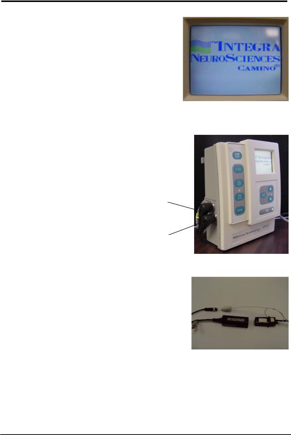
1.Turn on the MPM-1 by pressing the START/STOP button on the front panel. The MPM-1 will display the “Camino Logo”(Figure 2-1).
Figure 2-1 Camino Logo
2.Connect the Preamp Cable to the MPM-1 by inserting the two cable connectors in the appropriate receptacle (Figure 2-2). Note the red alignment marks on the cable connectors and the side panel.
Temperature
Transducer
Pressure
Transducer
Figure 2-2 Preamp Cable to MPM-1
3.Select the desired Camino Pressure Monitoring kit. Specific Directions For Use may be found in the User information insert provided with each Pressure Monitoring Kit.
Figure 2-3 Catheter to Preamp Cable
40201–C |
2-2 |
MPM-1 Technical Manual |
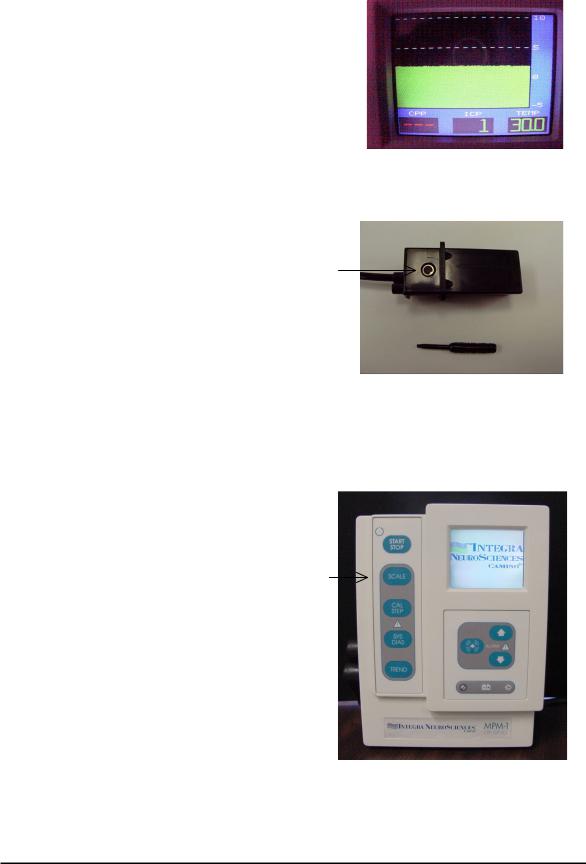
4.Remove the Catheter from the kit tray, and firmly connect the Transducer Connector(s) into the Preamp Connector(s) (Figure 2-3). (If a pressure only catheter is used, then the temperature connector will remain unconnected). After a short system test, the MPM-1 Display will change to the ICP/ICT display (Figure 2-4).
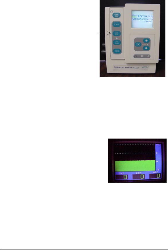
5.Before inserting the Catheter into the patient, ensure that the MPM-1 Display indicates an ICP Pressure of “0 mmHg”. If not, use the tool from the Catheter Kit to turn the zero adjustment (Figure 2-5) on the bottom side of the Transducer Connector until the ICP Pressure indicates “0 mmHg”. Also, ensure that the temperature is a reasonable value, such as room temperature, before insertion of the Catheter into the patient.
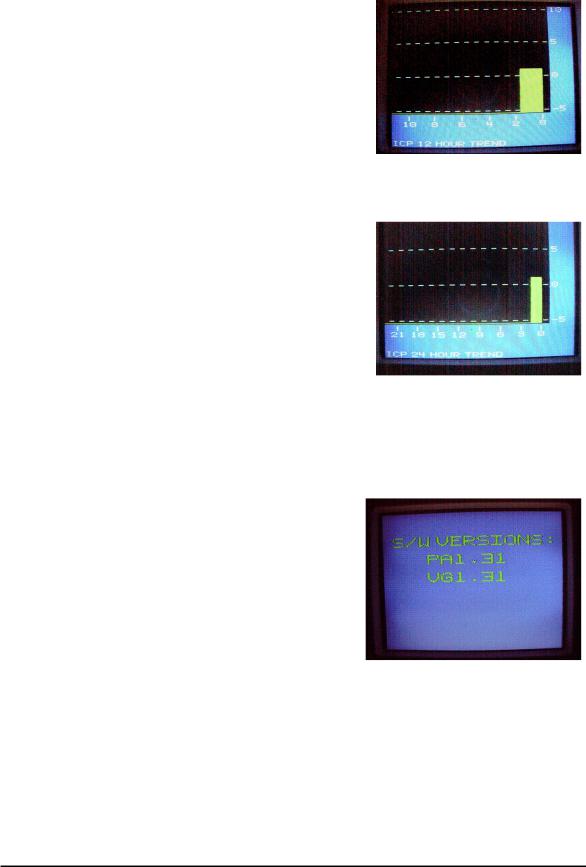
6.After the Catheter has been inserted into the patient, (see the catheter Directions For Use for proper insertion technique) select the appropriate scale by repeatedly pressing the SCALE button on the MPM-1 front panel (Figure 2-6).
Figure 2-4 CPP/ICP/ICT Display
Zero
Adjustment
Figure 2-5 ICP Catheter Transducer
Scale
Button
Figure 2-6 Scale Button
40201–C |
2-3 |
MPM-1 Technical Manual |
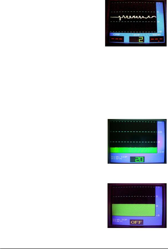
7.If the MPM-1 is connected to an external bedside monitor, the CAL STEP button (Figure 2-7) may be used to calibrate or balance the bedside monitor. Each press advances to the next mmHg value in the following series: 0, 20, 40, 100, 200 and back to 0. The CAL STEP momentarily interrupts normal pressure signal on both the MPM-1 and on the external bedside monitor. Press the CAL STEP button repeatedly until 0 mmHg is displayed on the MPM-1. While keeping the button depressed to maintain 0, simultaneously zero the bedside monitor, then release the CAL STEP button. Within a few seconds, the MPM-1 will return to the pressure display. Note that the CAL STEP button may be used at any time, and does not affect the transducer calibration.
8.Press the SYS/DIAS button to toggle between CPP, ICP, ICT and SYS, ICP, DIAS displays (Figure 2-8).
Cal Step
Button
Figure 2-7 CAL STEP Button
Figure 2-8 SYS/DIAS Display
40201–C |
2-4 |
MPM-1 Technical Manual |
9.Press the TREND button to display the mean ICP and CPP value recorded during the preceding 12 hours (Figure 2-9). With the next press of the trend button, the mean ICP and CPP for the preceding 24 hours will be displayed (Figure 2-10). Press again to return to the pressure display. To clear trend, turn MPM-1 off momentarily.
NOTE - The trend information will be lost if the MPM-1 is turned off or if the battery discharges completely and the MPM-1 turns itself off.
NOTE - ICT and CPP values will ONLY be displayed when using the appropriate Catheter and/or bedside monitor input connections.
NOTE - When not in use, the MPM-1 must be connected to AC power to maintain battery charge.
TO DISPLAY THE MPM-1
SOFTWARE VERSION
•Make sure that the MPM-1 is powered off.
•Connect the Pre-Amp cable.
•Insert a catheter to Pre-Amp cable.
•Press and hold the DOWN button.
•While keeping the DOWN button depressed, power on the MPM-1 by pressing the START/STOP button.
•Hold the DOWN button until the SOFTWARE VERSION appears on the screen (Figure 2-11).
•Wait approximately 5 seconds for the graph screen to appear.
Figure 2-9 12 Hour Trend
Figure 2-10 24 Hour Trend
Figure 2-11- Software Version Display
40201–C |
2-5 |
MPM-1 Technical Manual |
TO CHANGE THE GRAPH MODE
This feature is available on software version 1.29 and later.
•The graph mode can be either LINE or FILL (Figure 2-12).
•The initial default graph mode is FILL.
•The graph mode is saved every time Directions:
•Make sure the MPM-1 is powered off.
•Press and hold the SYS/DIAS button depressed, power on the MPM-1 by pressing the START/STOP button.
•Hold the SYS/DIAS button until the graph screen appears.
•Repeat the above to revert to the FILL Graph Mode.
TO SET HIGH ICP ALARM
•The initial default ICP ALARM is set to OFF. After that, the level is saved every time it is set.
•Reminder: The alarm sounds and the ICP parameter blinks when ICP
goes higher than the set point. Directions:
•While the MPM-1 is on, press the UP or DOWN button, view the Alarm Select Screen.
•Press the UP button to select the High ICP ALARM (Figure 2-13).
•Press the UP or DOWN button to set the ICP ALARM to the desired level.
•Wait approximately 5 seconds for ICP ALARM to be set.
•Pressing the DOWN button until the word “OFF” appears disables this alarm (Figure 2-14).
Figure 2-12 Line Graph Mode Display
Figure 2-13 High ICP Alarm
Figure 2-14 High ICP Alarm, OFF Mode
40201–C |
2-6 |
MPM-1 Technical Manual |
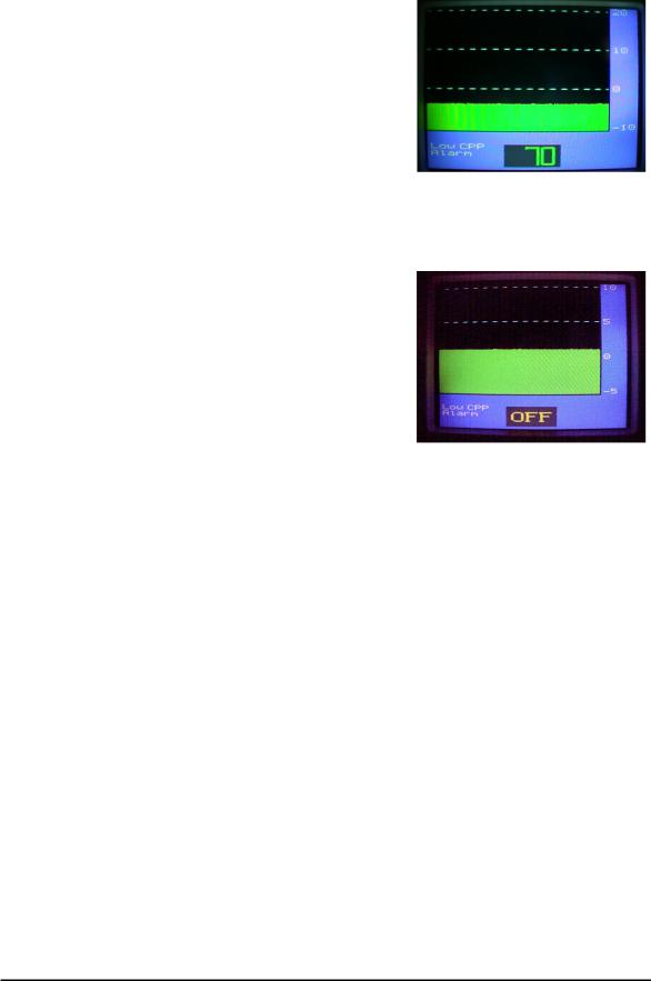
TO SET LOW CPP ALARM
This feature is available on software version 1.31 and later.
•The initial default CPP ALARM level is OFF. After that, the CPP ALARM level is saved every time it is set.
•Reminder: The alarm sounds and the CPP parameter blinks when CPP goes lower than the set point.
Directions:
•While the MPM-1 is on. Press the UP or DOWN button, view the Alarm Select Screen.
•Press the DOWN button to select the Low CPP ALARM (Figure 2- 15).
•Press the UP or DOWN button to set the CPP ALARM to the desired level.
•Wait approximately 5 seconds for CPP ALARM to be set.
•Pressing the DOWN button until the word “OFF” appears disables this alarm (Figure 2-16).
Figure 2-15 Low CPP Alarm
Figure 2-16 Low CPP Alarm, OFF Mode
40201–C |
2-7 |
MPM-1 Technical Manual |
TO SILENCE THE ALARM
•The initial default CPP ALARM and ICP ALARM levels are OFF. After that, the CPP ALARM and ICP ALARM levels are saved in memory every time they are set.
Directions:
•Press the SILENCE ALARM button. The ALARM DISABLED INDICATOR will flash and whichever parameter, ICP or CPP, was in alarm mode will now be silenced for 3 minutes and that parameter will flash on the screen (Figure 2-17).
NOTE: The parameter that is in alarm mode will blink (even if it has been silenced). If both alarms were in alarm mode when the SILENCE ALARM button was pressed, both alarms will be silenced. If one parameter (ICP or CPP) has been silenced and the other parameter goes into its alarm mode during the 3 minute silence period, the silence alarm mode is disabled (the alarm sounds).
BOTH ALARMS OFF
•As a warning, the ALARM DISABLED INDICATOR will be ON (and the alarms will be disabled) when both of the alarms have been set to OFF.
Silence
Alarm
Button
Alarm
Disabled
Indicator
Figure 2-17 Alarm Button & Indicator
40201–C |
2-8 |
MPM-1 Technical Manual |
Loading...