

Page 1
USER MANUAL
EPRO RACK 1.1K-3.4K
____________________________________________________________________________________________
(120217_ENG) Integra EPRO RACK 1.1K-3.4K - 1
ENGLISH
USER MANUAL
EPRO-RACK 1.1K – 3.4KVA
ONLINE DOUBLE CONVERSION UPS
User Manual:
• 220V (Europe: «Schuko» Zone)
• 110V (America: «NEMA» Zone)
USER MANUAL
EPRO RACK 1.1K-3.4K
____________________________________________________________________________________________
(120217_ENG) Integra EPRO RACK 1.1K-3.4K - 2
DO NOT connect laser printers, scanners, or copiers to this UPS.
High power devices may damage this UPS
.
1. SAFETY AND USE:
WARNING: This product has been designed to operate safely and reliably for years. Nevertheless, as it is an
electrical device, it is required to read and understand this manual. Keep manuals as references for future consults.
WARNING: This product has been designed to be used indoors, protected of water, direct sun light and extreme
temperatures. This device must not be used outdoors, close to moisture of heat sources.
WARNING: Do not set objects on this UPS. Handle with care. Do not block UPS ventilation.
WARNING: Make sure to connect this unit to proper power line according to selected model. The UPS Technical
Specs sticker shows power rating information. DO NOT connect this UPS to any of its own power outlets.
WARNING: UPS must be installed following instruction from this manual.
The manufacturer is not liable for any damage that might rise from misusing this unit or defective installation.
WARNING: Only computer related equipment can be connected to this UPS. DO NOT connect medical
equipments, life support equipments, microwave ovens, vacuum cleaners, refrigerators, or any other appliance to
this UPS.
WARNING: UPS must be checked, repaired and maintained by qualified personnel only. This product is locked by
screws.
WARNING – ELECTRIC SHOCK RISK:
Inside the UPS there are dangerous high voltages even when disconnected of power line, due to internal batteries
WARNING: In case of emergency turn off the UPS pressing Power Button, unplug it and call technical support.
Disposal
We strongly recommend disposing this UPS according to regulations in your country to prevent
possible environmental damages; besides some parts might be recycled.
BATTERY WARNING: DO NOT dispose batteries in fire as it might explode. DO NOT try to open
batteries, there are dangerous liquids inside.
Page 2
USER MANUAL
EPRO RACK 1.1K-3.4K
____________________________________________________________________________________________
(120217_ENG) Integra EPRO RACK 1.1K-3.4K - 3
SAFETY STANDARDS
EPRO & EPRO-RACK 1.1KVA - 1.7KVA
Low Voltage Directive:
EN62040-1-1:2003 An Uninterruptible Power Systems (UPS) Part 1-1: General and Safety Requirement for UPS
use operator access areas
EMC Directives:
EN62040-2: 2006 An Uninterruptible Power Systems (UPS) Part 2: Electromagnetic compatibility Class 2 (EMC)
IEC 61000-4-2: 2001 Electrostatic discharge immunity test
IEC 61000-4-3: 2006 Radiated radio frequency electromagnetic field immunity test
IEC 61000-4-4: 2004 Electrical fast transients/Burst immunity test
IEC 61000-4-5: 2005 Surge immunity test
IEC 61000-2-2: 2002 Compatibility levels for low frequency conducted disturbances and signaling in public low
voltage power supply systems
EN 61000-4-6: 2006
EN 61000-4-8: 2001
EN 61000-4-11: 2004
EPRO & EPRO-RACK 2.25KVA – 3.4KVA
Low Voltage Directive:
EN62040-1-1:2003 An Uninterruptible Power Systems (UPS) Part 1-1: General and Safety Requirement for UPS
use operator access areas
EMC Directives:
EN62040-2: 2006 An Uninterruptible Power Systems (UPS) Part 2: Electromagnetic compatibility Class 2 (EMC)
IEC 61000-4-2: 2001 Electrostatic discharge immunity test
IEC 61000-4-3: 2006 Radiated radio frequency electromagnetic field immunity test
IEC 61000-4-4: 2004 Electrical fast transients/Burst immunity test
IEC 61000-4-5: 2005 Surge immunity test
IEC 61000-2-2: 2002 Compatibility levels for low frequency conducted disturbances and signaling in public low
voltage power supply systems
EN 61000-4-6: 2006
EN 61000-4-8: 2001
EN 61000-4-11: 2004
USER MANUAL
EPRO RACK 1.1K-3.4K
____________________________________________________________________________________________
(120217_ENG) Integra EPRO RACK 1.1K-3.4K - 4
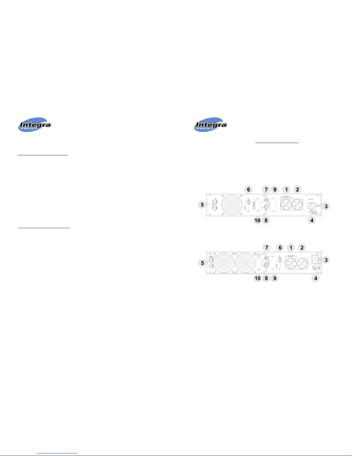
2.A- PRODUCT DESCRIPTION – REAR PANEL: 220V (EUROPE SCHUKO Outlets)
1. Programmable Outlets
2. Standard Outlets
3. AC Input
4. Input Breaker
5. Protected LAN network jacks
6. “EPO”: “Emergency Power Off”.
7. USB port
8. RS-232 port
9. Intelligent Slot for “SNMP” LAN cards
10. Connector for External batteries (EX
models).
EPRO-RACK 1.1KVA / 1.7K / 2.25KVA
EPRO-RACK 3.4KVA
Page 3
USER MANUAL
EPRO RACK 1.1K-3.4K
____________________________________________________________________________________________
(120217_ENG) Integra EPRO RACK 1.1K-3.4K - 5
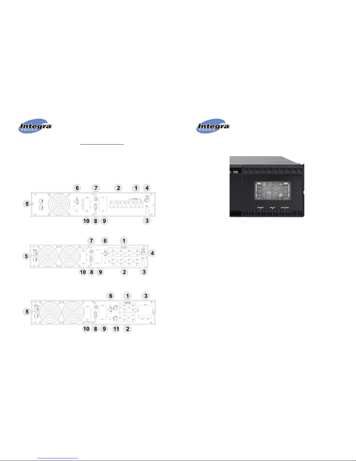
2.B- PRODUCT DESCRIPTION – REAR PANEL: 120V (AMERICA – NEMA Outlets)
1. Programmable Outlets
2. Standard Outlets
3. AC Input
4. Input Breaker
5. Protected LAN network jacks
6. “EPO”: “Emergency Power Off”.
7. USB port
8. RS-232 port
9. Intelligent Slot for “SNMP” LAN cards
10. Connector for External batteries (EX
models)
11. Output Breakers.
EPRO-RACK 1.1KVA / 1.7KVA
EPRO-RACK 2.25KVA
EPRO-RACK 3.4KVA
USER MANUAL
EPRO RACK 1.1K-3.4K
____________________________________________________________________________________________
(120217_ENG) Integra EPRO RACK 1.1K-3.4K - 6
FRONT PANEL: PUSH BUTTON FUNCTIONS
“ON / MUTE”
a) POWER ON: Keep selected during 2 seconds or longer.
b) BEEP MUTE: In battery mode: Keep selected during 5 seconds or longer to Mute acoustic alarm beep.
Some alarms cannot be muted as Bypass Warning or ERROR alarms.
c) AUTO-TEST: In normal mode: Keep selected during 5 seconds or longer to activate Auot-Test
function.
“OFF / ENTER”
a) POWER OFF UPSAPAGADO DEL UPS: Keep selected during 2 seconds to power off UPS
b) ENTER: Enter function works under configuration mode only. It works as confirmation or selection key
for accepting current option on LCD.
“SELECT”
a) TO SHOW UPS PARAMETERS AND VALUES: It is used to show on LCD UPS input and output
values as AC Input, DC battery voltage, Input Frequency, UPS output, output frequency, etc.
b) TO ACTIVATE CONFIGURATION: Keep selected during 5 seconds or longer
“ON / MUTE” + “SELECT”
TO ACTIVATE BY-PASS MODE: Under normal mode, by selecting these 2 keys at the same time
during 5 seconds or longer UPS changes from normal mode to bypass mode.
Page 4
USER MANUAL
EPRO RACK 1.1K-3.4K
____________________________________________________________________________________________
(120217_ENG) Integra EPRO RACK 1.1K-3.4K - 7
3. INSTALATION
3.1.- INTERNAL BATTERIES CONNECTION BEFORE INSTALLING
Before installing this product internal batteries must be connected. This product is delivered with internal batteries
disconnected to avoid battery damage during long storage times.
Paso 1: Open and remove front cover
Paso 2: Connect internal batteries to the UPS
Paso 3: Close front panel
USER MANUAL
EPRO RACK 1.1K-3.4K
____________________________________________________________________________________________
(120217_ENG) Integra EPRO RACK 1.1K-3.4K - 8
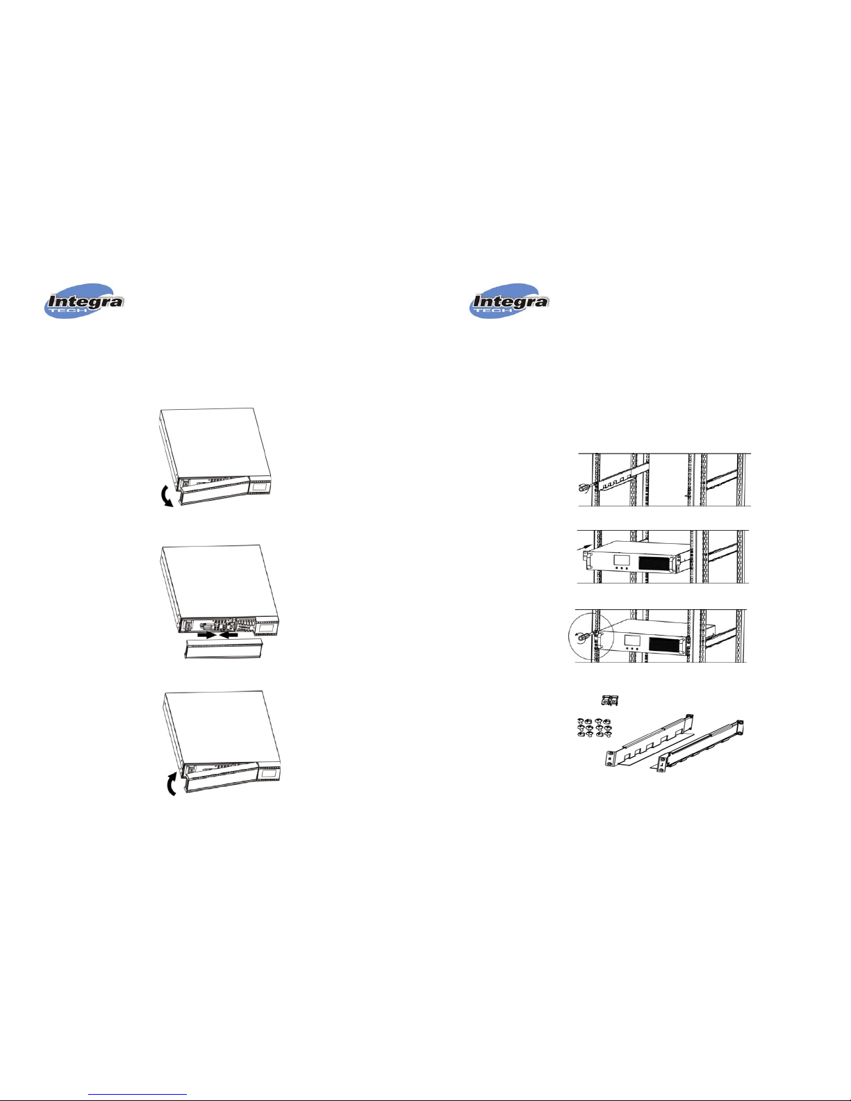
3.2.- RACK UPS INSTALLATION
Rack UPS must be installed using L-Shape type guides for supporting UPS weight. Usually this kind of supports is
provided with rack cabinets. If not, INTEGRA can provide telescopic guides as optional accessory.
Small black handles included with the UPS are only for locking purposes. UPS cannot be supported only by these
handles.
- Figure 1: Rack cabinet must include L-shape guide to support UPS.
- Figure 2: UPS must be installed on L-shape guides.
- Figure 3: Handles included with UPS are only for locking UPS to the cabinet but not for supporting
UPS weight.
- Figure 4: INTEGRA offers telescopic guides as optional accessory if it is required.
Figure 1:
Figure 2:
Figure 3:
Figure 4:
Page 5

USER MANUAL
EPRO RACK 1.1K-3.4K
____________________________________________________________________________________________
(120217_ENG) Integra EPRO RACK 1.1K-3.4K - 9
First Time:
CHARGE BATTERIES FOR 6 HOURS BEFORE CONNECTING YOUR EQUIPMENTS TO UPS
• This product leaves factory with battery fully charged, however during transportation and storage it may loose a
non determined part of its charge; therefore we recommend plugging it to Power Line for 6 hours before using the
UPS.
• Install this unit in any protected environment with a dust free air flow. Also corrosive vapours and conductive
contaminants must be avoided. Do not use UPS outdoors or where either temperature or humidity exceeds tech
specs. Install UPS at least 10 inches away from your monitor to avoid magnetic interference.
1.- Plug input AC power cord to an appropriate power outlet with Line-Neutral-Ground contacts.
• Some models come with input power-cord with appropriate plug for your country.
• 3KVA in 120V could come with input terminal block. For 3KVA-120V models input cable to be
connected to input Terminal Block must be AWG12 or wider (for lengths shorter than 50 feet – 15m).
Wire size is strongly affected by length and temperature. Input wire must be selected and installed by
qualified personnel according to local regulations.
2.- First time leave UPS recharging batteries during 6 hours before connecting your devices to the UPS to let
batteries recover charging level to offer full battery backup time.
3.- Connect your devices to be protected to UPS outlets. Take care to not overload UPS output by connecting
devices with higher power ratings than UPS power capacity. Laser printers, scanners and copiers frequently have
two different power ratings: in stand-by power ratings are very low compared with consumption rating during
operation. If this kind of products will be connected to the UPS operation power rating must be considering to size
total power consumption to be connected to UPS.
4.- EPO Function: Emergency Power Off function allows to power off UPS outlets when EPO input is open. When
EPO port is closed EPO function is disable. When EPO function is activated UPS will perform following actions:
a) Power Off all outlets,
b) Switch to STAND-BY mode,
c) Acoustic alarm is activated as continuous beep
d) Warning message Nº 20 is indicated on LCD.
To disable EPO mode and recovering normal mode contact switch or jumper in EPO port must be closed and UPS
must be powered On by selecting ON push button.
EXTERNAL BATTERIES OPTION
EPRO models with EX mark (like EPRO 3K-EX or EPRO-RACK 3K-EX) are able to be connected to external
battery cabinets (EX-BATT) to offer longer backup times.
This kind of models has internal batteries as other EPRO models but they can also be connected at any moment
to EX-BATT supplied by INTEGRA.
Special cables to connect EX-BATT to UPS are supplied inside the box of EX-BATT.
USER MANUAL
EPRO RACK 1.1K-3.4K
____________________________________________________________________________________________
(120217_ENG) Integra EPRO RACK 1.1K-3.4K - 10
3.3.- INSTRUCTIONS TO CONNECT EXTERNAL BATTERIES
1) Place EX-BATT case close to UPS. Only INTEGRA approved EX-BATT can be connected to UPS EX
series.
2) Check DC breakers are in OFF position (circuit OPEN)
3) Connect UPS to first EX-BATT using INTEGRA approved DC cable.
4) If more than one EX-BATT will be connected, then connect first EX-BATT to second EX-BATT and so
on in that way to other EX-BATT.
5) After all EX-BATT are connected, switch to ON position all DC breakers located in EX-BATT.
Important Note:
It is not recommendable to connect more than 3 external battery packs to the UPS since recharging time could
be too long.
External Battery Cabinet Characteristics:
Model: EX-BAT-R3
Total Batteries: 12 pieces per cabinet: 2 internal packs of 6 batteries 12V-9AH
Voltage DC: 82.1Vdc +/- 1%
Application: EPRO-Rack 3.4K “EX”
4. CONFIGURABLE PARAMETERS
Any configuration modification must be applied with UPS connected to AC line but in OFF or STAND-BY mode.
This UPS can be configured to work under some different modes. Some important functions can also be
configured in CONFIGURATION MODE:
a) Normal Mode: Also known as AC MODE. Under this mode UPS works as ONLINE UPS. UPS outlets are
supplied by AC power generated by UPS inverter circuit offering a clean power to your devices.
b) ECO Mode: Under this mode UPS works as OFF-LINE UPS. UPS outlets are supplied by AC input
source. UPS supervises input source to switch to ONLINE mode only when input source is out of range
This is not a recommendable mode for those critical applications that require ONLINE UPS.
Default mode set as factory is NORMAL MODE (Online UPS).
c) Output Voltage: It can be configured to any of 4 available values:
In 120Vac Models: 110Vac, 115Vac, 120Vac, 127Vac,
In 220Vac Models: 208Vac, 220Vac, 230Vac ó 240Vac
d) Output Frequency: It can be selected to 50Hz or 60Hz. Default configuration allows auto-selection to
match with frequency of input AC source.
NOTE: When conversion frequency mode is activated UPS power capacity can be reduced.
e) Programmable Outputs: There are 2 group of outlets:
• Standard Outlets: They works as expected in any UPS. This kind of outlets under battery keep powered until
batteries reach very low level or up to UPS receives power off command from software.
• Programmable Outlets: If programmable outlets function is configured, programmable outlets can be
powered off by internal timer before UPS detects very low battery level. Most common application for
programmable outlets is for connecting non critical devices to them so that backup time can be longer for
those critical devices connected in standard outlets.
Page 6

USER MANUAL
EPRO RACK 1.1K-3.4K
____________________________________________________________________________________________
(120217_ENG) Integra EPRO RACK 1.1K-3.4K - 11
5. OPERATION
This is UPS is ONLINE DOUBLE CONVERSION type and it has been designed to offer the most clear power
without switching transitions or dead times. In that way your hardware but also your valuable data will be safe when
your PC related equipment is connected to EPRO series UPS.
Power output is sine-wave type same as supplied by AC main source.
Depending of AC input source, this UPS can work under one of two following modes:
Normal AC Mode:
It is the default mode when AC input source is OK. Under this mode power output is generated
by UPS inverter. Inverter takes power from AC/DC converter feed by AC input source. AC input source is only used
under this mode to recharging batteries when necessary.
Battery Mode:
Also known as Inverter Mode. It is the mode when AC input source is out of range or black-out is
detected by the UPS. Under this mode power output is generated by UPS inverter that takes power from batteries.
There is no dead time (transition time is ZERO ms) related to switching from normal mode to battery mode since
load is always powered from inverter. This is main characteristic of an ONLINE UPS.
ECO Mode:
This UPS also offer a third operation mode name ECO MODE. Under this mode (selectable by LCD
configuration menu) UPS works as OFF-LINE UPS. Load is powered from AC input and UPS only switch to battery
mode when input is out of range or in black-out status. Transition time from ECO mode to Battery mode is not zero.
Typically is about 4ms that is why ECO Mode is not recommended for critical applications.
USER MANUAL
EPRO RACK 1.1K-3.4K
____________________________________________________________________________________________
(120217_ENG) Integra EPRO RACK 1.1K-3.4K - 12
6. FRONT LCD PANEL
Running Time in Battery Mode
Time symbol when battery mode is active
Indicates time in battery mode: H: hours, M: minutes, S: seconds
Failure Messages
Indicates failure detected
Indicates number code for detected failure. Error or Failure codes are listed
in this manual.
“MUTE”
Indicates MUTE function is active. Under this mode beeper is disabled.
OUTPUT Information
Indicates output values related to AC voltage, outputfrequency
Vac: Volts AC, Vdc: Volti DC, Hz: frequency units
Page 7

USER MANUAL
EPRO RACK 1.1K-3.4K
____________________________________________________________________________________________
(120217_ENG) Integra EPRO RACK 1.1K-3.4K - 13
Power consumption
(connected to UPS outlets)I
Indicates power output supplied by UPS:
0-25%,
26-50%,
51-75% y
76-100%.
Indicates overload at UPS output. Devices connected in UPS outlets load
UPS above UPS capacity.
Indicates short circuit at UPS output.
Programmable Outputs
Indicates programmable function is activated.
Operation Mode
Indicates UPS is connected to input AC source under normal range..
Indicates UPS is in battery mode.
Indicates UPS is in BYPASS mode.
Indicates ECO Mode is active
Indicates UPS inverter is running.
Indicates UPS outlets are powered.
Battery Information
Indicates battery charging level:
0-25%,
26-50%,
51-75% y
76-100%.
Indicates battery failure
Indicates low battery level
Input Information
Indicates input voltage, input frequency and DC battery voltage
Vac: Input voltage, Vdc: battery voltage, Hz: input frequency
USER MANUAL
EPRO RACK 1.1K-3.4K
____________________________________________________________________________________________
(120217_ENG) Integra EPRO RACK 1.1K-3.4K - 14
ACOSUTIC ALARM
Battery Mode: 1 “Beep” every 4 seconds
Battery Low: 1 “Beep” per second
Output Overload: 2 “Beeps” per second
UPS Failure: Continuous Beep
By-Pass Mode: 1 Beep every 10 seconds.
7. LCD TEXT MESSAGES
TEXT LCD TEXT Meaning
ENA
Enable (Habilitado)
DIS
Disable (Des-habilitado)
ESC
Escape (Salir)
HLS
High Limit for Baypass (Límite Alto para
Bypass)
LLS
Low Limit for Baypass (Límite Bajo para
Bypass)
BAT
Battery (Batería)
CF
Converter (Convertidor de Frecuencia)
EP
EPO (Emergency Power Off)
FA
Fan (Ventilador)
TP
Temperature (Temperatura)
CH
Charger (Cargador de Baterías)
Page 8

USER MANUAL
EPRO RACK 1.1K-3.4K
____________________________________________________________________________________________
(120217_ENG) Integra EPRO RACK 1.1K-3.4K - 15
8. UPS CONFIGURATION
* Configuration menu is activated by selecting SELECT push button at front panel during 5 seconds or longer. UPS
must be connected to input AC source but in stand-by mode (powered off).
* “OFF/Enter” button is used as confirmation key (Enter)
* “ON/Mute” is used to select upper option in menu.
* “SELECT” is used to select bottom option in menu.
Configuration Menu:
00: Initial Menu, Quit option
01: Output Voltage
02: CF Frequency Conversion Mode (to able or disable)
03: CF for configuring frequency value in Hz
04: ECO: to Able or Disable ECO Mode
05: ECO: To configure acceptable input voltage range in ECO mode.
06: By Pass: To able or disable by-pass function
07: By Pass: To configure acceptable input voltage range.
08: Programmable Outlets: To able or disable programmable outlets function
09: Programmable: To configure timer value in minutes for programmable outlets.
USER MANUAL
EPRO RACK 1.1K-3.4K
____________________________________________________________________________________________
(120217_ENG) Integra EPRO RACK 1.1K-3.4K - 16
01: Output Voltage Configuration
Output voltage value can be selected from 4 available values
02: CF: Enable or Disable
CF ENA: CF function enable
CF DIS: CF function disable
03: CF: Frequency value in Hz
Output frequency can be configured for battery mode:
BAT 50: 50Hz
BAT 60: 60Hz
If CF function is enable output frequency can be set in normal mode:
CF 50: 50Hz
CF 60: 60Hz
04: ECO: Enable or Disable
ENA: ECO enable (ON)
DIS: ECO disable (OFF)
05: ECO: Input Range Configuration
By Selecting UP/DOWN (“on/mute” y “select”) keys for selecting hi
limit HLS and low limit LLS of input range in ECO mode.
06: By Pass: Enable or Disable
ENA: Bypass enable
DIS: Bypass disable
07: By Pass: Input Range Configuration
By Selecting UP/DOWN (“on/mute” y “select”) keys for selecting hi
limit HLS and low limit LLS of input range in By-Pass mode.
Page 9

USER MANUAL
EPRO RACK 1.1K-3.4K
____________________________________________________________________________________________
(120217_ENG) Integra EPRO RACK 1.1K-3.4K - 17
08: Programmable Outlets: Enable or Disable
ENA: to enable programmable function.
DIS: to disable programmable function.
09: Programmable Outlets: Timer setting
0-999: to configure timer limit in minutes for powering off
programmable outlets.
9. LCD screens depending of Operation Mode
Operation Mode Description LCD
ONLINE
* UPS ON
* Input AC source OK
* UPS output generated by inverter
ECO
* UPS in ON
* ECO mode activated.
* Input AC source is OK
* UPS output feed from AC input to save
energy.
* UPS in ON
* ECO mode activated.
* Input AC source out of acceptable
range
* UPS output generated by inverter.
FREQUENCY
CONVERTER
FUNCTION
CF function enable to generate output
frequency as selected.
BATTERY MODE
When AC input source is out of range
Ups goes to battery mode to supply
output from taking energy from batteries.
USER MANUAL
EPRO RACK 1.1K-3.4K
____________________________________________________________________________________________
(120217_ENG) Integra EPRO RACK 1.1K-3.4K - 18
BYPASS
If UPS is overloaded by big consuming
load connected at UPS output, UPS
changes to BYPASS mode feeding
outlets from input AC source. This mode
can be set also by front panel (by
selecting “ON/MUTE” + “SELECT” at
same time).
STAND-BY
* UPS is OFF
* No power in UPS outlets.
* Input AC source is OK.
* Batteries are been charged
10. ERROR / FAILURE CODES ON LCD
FAILURE / ERROR CODE ICON
Bus failure 01
Hi BUS Voltage 02
Low BUS Voltage 03
Bus Unbalanced 04
Soft-start Inverter Failure 11
Inverter: Hi Voltage 12
Inverter: Low Voltage 13
Inverter output short circuit 14
Battery Very High Voltage 27
Battery Very Low Voltage 28
Over Temperature 41 x
Overload: UPS power output capacity has been exceeded. Inverter
cannot supply output.
43
Page 10

USER MANUAL
EPRO RACK 1.1K-3.4K
____________________________________________________________________________________________
(120217_ENG) Integra EPRO RACK 1.1K-3.4K - 19
11. ALARMS ON LCD
ALARM Description ICON on LCD Beep Alarm
Low battery
1 / s
Overload: hi power consumption detected at
UPS output.
2 / s
Battery disconnected
1 / s
Batteries overcharged
1 / s
Input Cable failure 1 / s
EPO enable
1 / s
FAN failure
1 / s
Over Temperature
1 / s
Battery charger problem
1 / s
Input out of range in bypass mode
1 / s
12. TROUBLESHOOTING TABLE
Problem Description Probable Root Cause Suggested Action
* LCD does not show input voltage
value
* AC input failure alarm active
(1 beep / 4s) however AC input source
is OK
Input power cord is not
connected
Check input power cord
connection.
Input power cord is connected
into UPS outlet.
Check input power cord
connection.
UPS cannot be powered on even AC
input is OK.
Beep alarm is active (1 beep/s) & LCD
shows:
EPO function is active.
Re-establish emergency power
off switch and set UPS in normal
mode.
USER MANUAL
EPRO RACK 1.1K-3.4K
____________________________________________________________________________________________
(120217_ENG) Integra EPRO RACK 1.1K-3.4K - 20
UPS cannot be powered on even AC
input is OK.
ON push button is not been
selected properly
Push ON button during 2
seconds or longer
1 beep / s alarm is active and LCD
shows:
Input Line and Neutral are
swapped
Rotate UPS plug at wall socket
to allow correct line-neutral
connection. This suggestion is
only valid for Schuko power plug
type.
1 beep / s alarm is active and LCD
shows:
Internal or external batteries are
not properly connected
Check battery connection.
* Code 27
* Active:
* Continuous beep
Very high voltage at batteries or
charger failure
Batteries and charger must be
inspected by qualified personnel
* Code 28
* Active:
* Continuous beep
Very low voltage at batteries or
charger failure
Batteries and charger must be
inspected by qualified personnel
* Intermittent: +
* 2 beeps per second.
UPS overloaded Disconnect devices from UPS
outlets until solving overload
* Intermittent: +
* 2 beeps per second.
* By-Pass activated
UPS overloaded. UPS has
changed to BYPASS mode to
avoid internal damage.
Disconnect devices from UPS
outlets until solving overload
A
fter repetitive small overloads,
UPS has changed to BYPASS
mode.
Disconnect devices from UPS
outlets until solving overload.
Then power off UPS and re-star
again.
* Code 43
* Active:
* Continuous beep
UPS has been automatically
powered off because overload.
Disconnect devices from UPS
outlets until solving overload.
Then power ON.
* Active: on LCD.
* Continuous beep
UPS has been automatically
powered off because short
circuit detected at output.
Check short circuit problem in
devices connected to UPS
Page 11

USER MANUAL
EPRO RACK 1.1K-3.4K
____________________________________________________________________________________________
(120217_ENG) Integra EPRO RACK 1.1K-3.4K - 21
* Any of following codes indicated on
LCD:
1, 2, 3, 4, 11, 12, 13 o 41
* Continuous beep
Internal Ups failure detected.
UPS working in any of following
modes:
1. UPS output powered in
BYPASS mode
2. UPS outlets powered off
Call service support
Very short backup time Batteries can be discharged
because recent use..
Let UPS recharge batteries
during 6 hours before check
backup time again.
Battery can be degraded
because long lifetime.
Batteries must be replaced by
new batteries.
* Intermittent: +
* 1 beep per second.
FANs blocked or damaged Check FANs and call service
support if problem cannot be
solved
13. CONTROL SOFTWARE
Our control software offers huge capabilities to monitor your UPS and configure key shutdown parameters. Also
event and data log are available in software options.
Main software features are:
• Friendly human interface to UPS.
• Controlled files saving and OS shutdown when blackout is detected.
• Configurable scheduled shutdown and Auto-tests
Some UPS models include software CD inside the box. Others allow software downloaded from our website:
www.integra-ups.com.
14. BATTERIES MAINTENANCE
14.1.- BATTERY CARE
When battery backup time is noticeable shorter it is time to replace batteries. To get longer lifetime we recommend applying
a deep discharge every 3 months. Operation temperature should be below 25ºC.
RECHARGING TABLE FOR LONG STORAGE
When UPS is storage periodic recharge must be performed as indicated in below table:
Storage Temperature Recharge Frequency Recharge Time
-25°C to +30°C 3 months 6 hours
+30°C to +45°C 2 months 6 hours
USER MANUAL
EPRO RACK 1.1K-3.4K
____________________________________________________________________________________________
(120217_ENG) Integra EPRO RACK 1.1K-3.4K - 22
14.2.- BATTERIES REPLACEMENT:
This UPS has been designed to allow easy and safety battery replacement
Paso 1: Remove front cover and disconnect internal
batteries
Paso 2: Take out battery kit from UPS
Paso 3: Replace old batteries using equivalent
batteries with same voltage and capacity in AH.
Follow instructions of 15.3
Paso 4: Reconnect batteries, assembly battery
kit and install it inside the UPS.
Paso 5: Reconnect battery kit to UPS Paso 6: Close front cover
Page 12

USER MANUAL
EPRO RACK 1.1K-3.4K
____________________________________________________________________________________________
(120217_ENG) Integra EPRO RACK 1.1K-3.4K - 23
14.3.- BATTERY ASSEMBLY INSTRUCTIONS:
Battery quantity depends of UPS model. Check specification table to know battery quantity and type for your UPS.
3 Batteries Kit
1.- Remove batteries from plastic assembly 2.- Connect new batteries in series as indicated
below
3.- Place batteries inside plastic assembly 4.- Close battery assembly
5.- Using a DVM, check battery assembly DC voltage is closet o 37.5 Vdc (3 x 12.5Vdc each). If measured voltage
is not correct probably there is a wrong connection. Check, correct and confirm.
4 Batteries Kit
1.- Remove batteries from plastic assembly 2.- Connect new batteries in series as indicated
below
3.- Place batteries inside plastic assembly 4.- Close battery assembly
5.- Using a DVM, check battery assembly DC voltage is closet o 50 Vdc (4 x 12.5Vdc each). If measured voltage is
not correct probably there is a wrong connection. Check, correct and confirm.
USER MANUAL
EPRO RACK 1.1K-3.4K
____________________________________________________________________________________________
(120217_ENG) Integra EPRO RACK 1.1K-3.4K - 24
6 Batte
r
ies Kit
1.- Remove batteries from plastic assembly 2.- Connect new batteries in series as indicated
below
3.- Place batteries inside plastic assembly 4.- Close battery assembly
5.- Using a DVM, check battery assembly DC voltage is closet o 75 Vdc (6 x 12.5Vdc each). If measured
voltage is not correct probably there is a wrong connection. Check, correct and confirm.
.
Page 13

USER MANUAL
EPRO RACK 1.1K-3.4K
____________________________________________________________________________________________
(120217_ENG) Integra EPRO RACK 1.1K-3.4K - 25
15. WARRANTY AND SUPPORT
Support: When a failure or problem is detecte d pl ease che ck tr oubl esh ooti ng t able i n this manu al . If problem ca nn ot be sol ved please c ontact
authorized service center or authorized dealer.
Batteries: Rechargeable batteries can be charged and discharged hundreds of times. However they will eventually wear out. This is not a
defect or failure so that batteries wear out is not covered by warranty.
Battery lifetime will depend of operative conditions like worki ng temperature and type and frequency of discharging cycles. Higher the
temperature shorter will be the lifetime. Frequent and deep discharging cycles also will short lifetime. For critical applications batteries should
be revised and replaced periodically.
Long storage without required recharging will wear out batteries. This situation is not covered by this limited warranty since this is not
considered as a defect. Check recharging instructions on user manual.
Conditions Limited Warranty “PRO11”
1.- Subject to the conditions of this limited warranty, this product is warranted to be free from defects in materials and workmanship at the time
of its original purchase by end user.
In Europe warranty time is 2 years on electronic parts and batt eries.
In America warranty time is 1 year on electronic parts and 1 year on batteries.
Standard warranty times could vary depending on country/regi on or extended by purchasing warranty options. Please check warranty
conditions by country/region in our web www.integra-ups.com.
2.- If during the warranty period, this product fai ls to operate under normal use and service, due to defects in materials or workmanship,
authorized distributor or service center will, at their option, either repair or replace the product in accordance with terms and conditions
stipulated herein. Transportation expenses are not covered by this limited warranty.
3.- Warranty is valid only if the original purchasing d ocum ent issu ed to o rigi n al purc haser by a utho ri zed di stri buto r o r deal er, spe ci fying dat e of
purchase, serial number and name of the dealer, is presented wit h the product to be revised. INTEG RA and authori zed partners re serve the
right to refuse warranty service if any of this informat ion has been removed, changed or missing in original purchasing document.
4.- If product is repaired or replaced, repaired or replaced product will be warranted for the remaining time of the original warranty or for 90
days from date of repair or replacement, whichever is longer.
5.- INTEGRA or their distribution/service partners rese rve the right to char ge handling fee or tra nsportation cost s if returned p roduct is free of
failure or out of warranty period because any of the rea sons described in this warranty.
6.- If product is out of warranty a reparation or replacement proposal will be sent to the user for his approval. If proposal is not accepte d
service center will try to send back product to the user with transportation costs covered by user. If delivery fails twice, product will be hold to
let user pick up the product. After this period product would be disposed by service center and user will not be able to rises any claim.
7.- Rechargeable batteries will definitively wear out even under normal operation and conditions. This is not a defect or failure so that it is not
covered by this warranty.
8.- Warranty does not cover product failures caused by: improper storage or longer than 6 months storage wit hout required recharging,
inadequate installation or maintenance, misuse, accidents, fire or floods. In these cases warranty will be considered void.
9.- This warranty does not cover product failures caused by i nstallations, modifi cations or repair or openi ng of the product pe rformed by non
authorized person.
10.- This product can include protection devices li k e input f use or inp ut br ea ker. Act iv ati on of t his ki nd of device s is not a failure it is caused by
an improper product installation. Input fuse or break er can be easily reset or replaced by user.
11.- This warranty does not cover damages produced during transp ortation from user to technic al service caused by i mproper packing of the
product by user.
12.- Warranty time could be extended to 3 years depending on market or products. Contact your authorized deale r f or additional information.
13.- Warranty terms and conditions cannot be modi fied or extended by third parties without written appro val of INTEGRA.
Limited Warranty “PRO11”
- If hardware product fail to work as warranted above, the maximum liability of INTEGRA under this limited warranty is expressly limited to the
lesser of the price you have paid for the product or the cost of repairing or replacement of any har dware components that malfunction in
conditions of normal use.
- In no event will INTEGRA be liable for any damages caused by the product or the failure of the product to perform, including any lost profits
or savings or special, incidental, or consequential dama ges. INTEGRA is not l iable for any claim ma de by a third party o r made by you for a
third party.
- INTEGRA does not warrant that the operation of this product will be uninterrupte d or error -free. I NTEGRA is not resp onsible f or damage tha t
occurs as a result of your failure to follow the instructions intended for this hardware product.
USER MANUAL
EPRO RACK 1.1K-3.4K
____________________________________________________________________________________________
(120217_ENG) Integra EPRO RACK 1.1K-3.4K - 26
16. SPECIFICATIONS TABLE (For Models 120Vac and 220Vac)
INPUT / ENTRADA
Frequency Range / R ango de Frecuencia
Output Regulat ion / Ra ngo de S a lida:
Eco Mode
AC Mode / Modo Normal
Battery Mode / Modo Batería
Technology / Tecnología
Qty&Type / Cantidad&Tipo (Model 220V):
Qty&Type / Cantidad&Tipo (Model 120V):
Charging Voltage / V oltaje del cargador (Model 220V):
Charging Voltage / V oltaje del cargador (Model 120V):
Ty pic al Recharge Time / T. de Reca rg a
Charging Amps / C or rie nt e de Car ga
Prog. Outlet s / Salidas Prog . ( Model: 230Vac) *N2
Prog. Outlet s / Salidas Prog . ( Model: 120Vac) *N2
DxWxH / Prof. X Ancho X Altura (mm)
Net Weight / Peso Neto (kgs)
Operating Temperature / Temp. de Operación
2.250VA / 1. 600W 3.400VA / 2.400W
3 x 12V-7AH 6 x 12V-9AH 6 x 12V - 9AH
41.0 VDC +/- 1% 82.1 VDC +/-1% 82.1 VDC +/-1%
Range / Rango - Vac @ 50% load Model 120V: 50Vac-150V ac / Model 220V: 110Vac-300Va c
40 Hz - 70Hz
EPRO-RACK 1.7K 2.25K 3.4K
Capacity / Capacidad
1.700VA / 1. 200 W
Power Factor / Factor de Potencia > 0.99 @ 100% lo ad
Input Current THDi / T HDi de Corriente de Entrada < 7% @ 100% load
Range / Rango - Vac @ 100% load Model 120V: 80Vac-150V ac / Model 220V: 160Vac-300Va c
OUTPUT / S A LID A
Voltage Output / Voltaje de Salida AC: (*N1) Model 120V: 110/115/120 / 12 7Vac - Model 220V: 20 8/ 2 20/ 23 0/ 2 40Vac
+/-3%
Frequency / Frecuencia (Bat t . Mode)
(*N3) 50 Hz +/- 0.25 Hz - 60Hz +/- 0.3 Hz
> 85% > 88%
Current Cres t Ra t io / Factor de Cresta 3:1 @ 100% load
Harmonic Distortion / Dis t . Armónica (THDv) < 3% @ Linear Load / Carga Lineal / <6% @ No Linear Load / Car ga no Lineal
AC to Inverter / T iempo de AC a Inversor
0 ms
OVERLOAD/ SOBRECARGA
100%~110%: (wa rning -a lar ma) / 110% ~ 130% : 1min: bypass / > 130% : 1s : bypass
100%~110%: (warning-alarma) / 110%~130%: 30s: shutdown / >130% : 1s: shut down
BATTERIES / BATERIAS
Waveform / F orma de Onda Pure Sinewave / Sinusoidal Pura
EFFICI ENCY / EFICIENCIA
> 93% > 93%
A
C Mode / Modo AC
UPS status, Load level, Bat t er y, I nput/Output voltage, Dis charge timer, and Fault conditions
Estado del UPS, Consumo, Baterías, Voltaje E ntrada/Salida, Aut onomí a, D iagnos tico Fallas
Sealed Lead A cid VRLA-AGM / Sellada de Libr e Mant enimient o VRLA - AGM
3 x 12V-7AH 4 x 12V-9AH 6 x 12V - 9AH
4 Hours for 90% capacity / 4 Horas para recuperar el 90% de carga
1.0 A (Max.)
CEE 7/4 (Schuko) x 1
PHYSICAL / FISICAS: UPS RACK Type
ALARM / ALARMAS
Beep Alar m / Alarma sonora:
Battery Mode, Low batt ery, Over load, Failure / Modo Batería, B aja baterí a, S obrecargas, Falla
41.0 VDC +/- 1% 54.8 VDC +/-1% 82.1 VDC +/-1%
INDICATORS / INDICADORES
LCD / Pantalla d e Cr is t al Liqu ido ( LC D)
Std. Outlets / Salidas Es t ándar (Model: 120V ac)
NEMA5-15R x 2 NEMA5-20R x 4 NEMA5-20R x 2
Std. Outlets / Salidas Es t ándar (Model: 230V ac)
CEE 7/4 (Schuko) x 1 CEE 7/4 (Schuko) x 1 CEE 7/4 (Schuko) x 1
CEE 7/4 (Schuko) x 1 CEE 7/4 (Schuko) x 1
NEMA5-15R x 2 NEMA5-20R x 4 NEMA5-20R x 2
438x88x480 [2U] 438x88x600 [2U] 438x88x600 [ 2U]
18.5 20.6 29
OPERATION A L C ON D ITION S / CONDICION E S DE OP E R A C I
Ó
N
Relative Humidity / Humedad relativa < 95 % RH (non-condensing / no condensante)
0 - 40 ºC
Noise Level / Ruido Producido < 45dBA @ 1 m
COMMUNICATION / COMUNICACION
Smart RS-232 & USB
Windows 98 SE / ME/NT 4.x/2000/2003/XP/Vista/ 2008 / Windows 7; Linux; Unix; Mac OS
SNMP Intelligent Port:
LAN Card S NMP type - optional / Comunicación con LAN mediante SN MP opcional
AS400 I n t er face (optional comm. Card) / I nt e rfaz con AS400 (tar jet a opcional)
 Loading...