


Multi-Channel Hipot Tester
GPT-9500 Series
USER MANUAL
ISO-9001 CERTIFIED MANUFACTURER

This manual contains proprietary information, which is protected by
copyright. All rights are reserved. No part of this manual may be
photocopied, reproduced or translated to another language without
prior written consent of Good Will company.
The information in this manual was correct at the time of printing.
However, Good Will continues to improve products and reserves the
rights to change specification, equipment, and maintenance
procedures at any time without notice.
Good Will Instrument Co., Ltd.
No. 7-1, Jhongsing Rd., Tucheng Dist., New Taipei City 236, Taiwan.

Table of Contents
Table of Contents
SAFETY INSTRUCTIONS .................................................. 5
GETTING STARTED .......................................................... 9
GPT-9500 Series Overview ................... 10
Front Panel Overview ........................... 14
Rear Panel Overview ............................ 18
Status Bar ............................................ 21
Set Up .................................................. 23
OPERATION .................................................................. 31
Menu Tree ............................................ 33
Test Lead Connection ........................... 39
MANU Tests ........................................ 40
AUTO Tests .......................................... 90
UTILITY ........................................................................ 139
System Setting ................................... 141
Test Setting ........................................ 154
Interface Setting ................................ 181
EXTERNAL CONTROL ................................................... 190
External Control Overview .................. 191
REMOTE CONTROL ...................................................... 195
Interface Configuration ...................... 196
Command Syntax ............................... 200
Command List ................................... 202
APPENDIX .................................................................... 273
Fuse Replacement .............................. 273
Test Errors ......................................... 274
3

GPT-10000 Series User Manual
Status System .................................... 275
GPT-9500 Specifications .................... 276
GPT-9503/9513 Dimensions .............. 281
Declaration of Conformity .................. 282
INDEX .......................................................................... 283
4

SAFETY INSTRUCTIONS
WARNING
Warning: Identifies conditions or practices that
could result in injury or loss of life.
CAUTION
Caution: Identifies conditions or practices that
could result in damage to the instrument or to
other properties.
DANGER High Voltage
Attention Refer to the Manual
Protective Conductor Terminal
Frame or Chassis Terminal
Earth (ground) Terminal
SAFETY INSTRUCTIONS
This chapter contains important safety
instructions that you must follow during
operation and storage. Read the following before
any operation to ensure your safety and to keep
the instrument in the best possible condition.
Safety Symbols
These safety symbols may appear in this manual or on the
instrument.
5

GPT-9500 Series User Manual
Do not dispose electronic equipment as unsorted
municipal waste. Please use a separate collection
facility or contact the supplier from which this
instrument was purchased.
General
Guideline
CAUTION
Do not place any heavy object on the
instrument.
Avoid severe impact or rough handling that
leads to damaging the instrument.
Do not discharge static electricity to the
instrument.
Use only mating connectors, not bare wires, for
the terminals.
Do not block the cooling fan opening.
Do not disassemble the GPT-9500 unless you are
qualified.
Position
Guideline
WARNING
The rear position of the GPT-9500 should be
placed in an area with easy accessible for power
disconnection, that is, unplugging the power
cord with ease.
Keep away from the device under test which
connects with the GPT-9500 when test is
underway. In addition, while test is ongoing,
never touch the device under test, the GPT-9500
as well as other relevant units.
Any inappropriate manner that is unspecified
by the manufacturer may result in irreversible
harms or impaired protection by the GPT-9500.
Safety Guidelines
6

SAFETY INSTRUCTIONS
(Measurement categories) EN 61010-1:2010 specifies the
measurement categories and their requirements as follows. The
GPT-9500 does not fall under category II, III or IV.
Measurement category IV is for measurement performed at the
source of low-voltage installation.
Measurement category III is for measurement performed in the
building installation.
Measurement category II is for measurement performed on the
circuits directly connected to the low voltage installation.
Power Supply
WARNING
AC Input voltage range:
AC 100V – 240V ± 10%
Frequency: 50Hz/60Hz
To avoid electrical shock connect the protective
grounding conductor of the AC power cord to
an earth ground.
Cleaning the
GPT-9500
Disconnect the power cord before cleaning.
Use a soft cloth dampened in a solution of mild
detergent and water. Do not spray any liquid.
Do not use chemicals containing harsh material
such as benzene, toluene, xylene, and acetone.
Operation
Environment
Location: Indoor, no direct sunlight, dust free,
almost non-conductive pollution (Note below)
Relative Humidity: ≤ 70% (no condensation)
Altitude: < 2000m
Temperature: 0˚C~40˚C
7

GPT-9500 Series User Manual
(Pollution Degree) EN 61010-1:2010 specifies the pollution degrees
and their requirements as follows. The GPT-9500 falls under degree
2.
Pollution refers to “addition of foreign matter, solid, liquid, or
gaseous (ionized gases), that may produce a reduction of dielectric
strength or surface resistivity”.
Pollution degree 1: No pollution or only dry, non-conductive
pollution occurs. The pollution has no influence.
Pollution degree 2: Normally only non-conductive pollution
occurs. Occasionally, however, a temporary conductivity caused
by condensation must be expected.
Pollution degree 3: Conductive pollution occurs, or dry, non-
conductive pollution occurs which becomes conductive due to
condensation which is expected. In such conditions, equipment
is normally protected against exposure to direct sunlight,
precipitation, and full wind pressure, but neither temperature
nor humidity is controlled.
Storage
environment
Location: Indoor
Temperature: -10°C to 70°C
Relative Humidity: ≤ 85% (no condensation)
Disposal
Do not dispose this instrument as unsorted
municipal waste. Please use a separate collection
facility or contact the supplier from which this
instrument was purchased. Please make sure
discarded electrical waste is properly recycled to
reduce environmental impact.
8

GETTING STARTED
GPT-9500 Series Overview .............................................. 10
Series lineup...................................................................................10
Lineup Overview ..........................................................................11
Main Features ................................................................................11
Accessories .....................................................................................12
Package Contents ..........................................................................13
Front Panel Overview ..................................................... 14
GPT-9503/9513 ..............................................................................14
Rear Panel Overview ...................................................... 18
GPT-9503/9513 ..............................................................................18
Status Bar ...................................................................... 21
Set Up ........................................................................... 23
Tilting the Stand ............................................................................23
Line Voltage Connection and Power Up ...................................24
How to edit parameter value promptly .....................................25
Workplace Precautions ................................................................27
Operating Precautions ..................................................................28
Basic Safety Checks .......................................................................30
GETTING STARTED
This chapter describes the safety analyzer in a
nutshell, including its main features and front /
rear panel introduction. After going through the
overview, please read the safety considerations in
the Set Up chapter.
9

GPT-9500 Series User Manual
GPT-9500 Series Overview
Series lineup
The GPT-9500 Series are multi-channel AC/DC withstanding
voltage and insulation resistance safety tester.
The GPT-9513 is AC/DC withstanding voltage and insulation
resistance tester with 8 channels scan – Hi & Lo setup functions.
The GPT-9503 is AC/DC withstanding voltage and insulation
resistance tester with 8 channels scan – Hi setup functions.
For the all models, the testing terminals are also mirrored on the
rear panel for added safety and for more permanent safety testing
environments.
The GPT-9500 Series can store up to 501 manual tests, and run up
to 99 manual tests sequentially within an automatic test, allowing
the safety testers to accommodate any number of safety standards,
including IEC, EN, UL, CSA, GB, JIS and others.
Note: Throughout this user manual, the terms ACW, DCW and IR,
refer to AC Withstanding, DC Withstanding and Insulation
Resistance testing, respectively.
10

GETTING STARTED
Model name
ACW
DCW
IR
Scan - Hi
Scan - Lo
GPT-9503
GPT-9513
Performance
ACW: 5kVAC
DCW: 6kVDC
IR: 50V~1kV
8-CH Scanner
Features
Ramp up time control
Fall time control
Safety discharge
501 test conditions (MANU mode)
99 steps per group (AUTO mode)
99 groups for total 500 memory locations
(AUTO mode)
Over temperature, voltage and current
protection
View, Edit, Ready, Test, Stop, High Voltage and
Pass, Fail indicators
Interlock (configurable)
Interface
RS232/USB interface for programming
Signal I/O port for pass/fail/test monitoring
and start/stop control
Interlock terminal for safety operation
Lineup Overview
Main Features
11

Accessories
Standard
Accessories
Part number
Description
GHT-115 x 1*
Test lead set
GHT-116B x 1*
Test lead (Black)
GHT-116R x 8*
Test lead (Red)
Region dependent
Power cord
N/A
Interlock wire
* Please refer to the packing list since the accessories may vary.
Optional
Accessories
Part number
Description
GHT-205
High Voltage Test Probe
GHT-113
High Voltage Test Pistol
GTL-232
RS232C cable
GTL-246
USB cable (A to B type)
GPT-9500 Series User Manual
12

GETTING STARTED
Opening the box
Contents
(single unit)
GPT-9500 unit
Quick Start Guide
User manual CD
Power cord x1
(region dependent)
GHT-115 test lead x1*
GHT-116B test lead x 1
(Black) *
GHT-116R test leads x 8
(Red) *
Interlock wire
* Please refer to the packing list since the accessories may vary.
Note
Keep the packaging, including the box, polystyrene
foam and plastic envelopes should the need arise
to return the unit to GW Instek.
Package Contents
Check the contents before using the GPT-9500 series.
13

GPT-9500 Series User Manual
STOP
START
POWER
PASS
FAIL
PAGE
ESC
UTILITY
GPT
AC / DC Withstanding Voltage /
Insulation Resistance / Scanner
Tester
HIGH VOLTAGE
CAUTION
5.0 kVAC MAX. 6.0 kVDC MAX.
RETURNCONTINUITY
HI-POT & IR
: LONG PUSH
LOCAL
HARDCOPY
-
9503
1
2
4
G E
C
B
A
9
3
F D
5 6 7 8
Item
Description
1
STOP Button
2
START Button
3
POWER Switch
4
Soft Keys (Green Zone)
5
Scroll Wheel
6
USB A-Type Host Port
7
ESC/LOCAL Key
8
UTILITY/HARDCOPY key
9
CONTINUITY Terminal
A
RETURN Terminal
B
HIGH VOLTAGE Output Terminal
C
HIGH VOLTAGE Indicator
D
PAGE Key
E
PASS/FAIL Indicators
F
Arrow Keys
G
Display
Front Panel Overview
GPT-9503/9513
14

GETTING STARTED
STOP button
The STOP button is used to
stop/cancel tests. The STOP button
will also put the tester in the READY
status to begin testing.
START button
The START button is used to start tests.
The START button can be used to start
tests when the tester is in the READY
status. Pressing the START button will
put the tester in the TEST status.
POWER switch
Turns the power on. The tester will
always start up with the AUTO (0)
test setting display.
Soft Keys
The Soft keys correspond to the menu keys directly
above on the main display.
Scroll wheel
The scroll wheel is used to edit
parameter values. Be aware that
faster the scroll speed, bigger the
value digits can be set and vice versa.
USB Host Port
It can connect with USB flash drive
for parameter storage and firmware
upgrade. Also, it is available for
screenshot hardcopy in association
with the Hardcopy key.
ESC/LOCAL Key
ESC allows user to return to
previous page. LOCAL switches
operation back to local mode from
remote mode
15

GPT-9500 Series User Manual
UTILITY/
HARDCOPY key
UTILITY changes to the main utility
setting page. Long press
HARDCOPY key for 1 second to take
a screenshot. Make sure an USB flash
disk is inserted before the action.
CONTINUITY
terminal
The CONTINUITY terminal
(red) is used for CONT
(Continuity) test. Refer to page
102 for test lead connection of
CONTINUITY.
RETURN
terminal
The RETURN terminal (black)
is used for ACW, DCW and IR
tests.
HIGH VOLTAGE
output terminal
The HIGH VOLTAGE terminal
output is used for outputting
the testing voltage in ACW,
DCW and IR tests. The
terminal is recessed for safety.
This terminal is used in
conjunction with the RETURN
terminal.
HIGH VOLTAGE
indicator
The HIGH VOLTAGE
indicator will light up red
when an output terminal is
active. Only after the test has
finished or stopped will the
indicator turn off.
PAGE Key
It is used to change among
different pages concerning
parameter editing or AUTO
mode displays.
16

GETTING STARTED
PASS/FAIL
indicators
The PASS and FAIL indicators
light up upon a PASS or FAIL
test result at the end of a
MANU test or AUTO test.
Arrow Keys
The arrow keys are used to
select the digit of a value that
is being edited.
Display
4.3” Color TFT LCD display in 480 X 272 resolution
17

GPT-9500 Series User Manual
SIGNAL I / O
LOCK
RS232
OUTPUT
GND
TO AVOID ELECTRIC SHOCK THE POWER CORD
PROTECTIVE GROUNDING CONDUCTOR MUST BE
ONLY WITH SPECIFIED TYPE AND RATED FUSE.
NO OPERATOR SERVICEABLE COMPONENTS INSIDE.
DO NOT REMOVE COVERS. REFER SERVICING TO
FOR CONTINUED FIRE PROTECTION. REPLACE
CONNECTED TO GROUND.
QUALIFIED PERSONNEL.
WARNING
SER. NO. LB
DO NOT TOUCH THE HIGH VOLTAGE TERMINALS DURING TESTING WHEN THE HV INDICATOR LIGHTS UP !
HIGH VOLTAGE
INDICATOR
AC 100 240V
50/60Hz 400VA MAX.
FUSE RATINGT4A 250V
FROM THE INSTRUMENT BEFORE
REPLACING THE FUSE.
ENSURE THE POWER IS REMOVED
RETURN
HIGH VOLTAGE
CAUTION5.0 kVAC MAX.
6.0 kVDC MAX.
INTER
CH 1 CH 2 CH 3 CH 4 CH 5 CH 6 CH 7 CH 8
TEST
3
9
1 2 4 5 6 8
A
7
B
Item
Description
1
RS232 Interface Port
2
USB B-Type Interface Port
3
Signal I/O Port
4
INTERLOCK Terminal
5
TEST OUTPUT Switch
6
Fan 7 HIGH VOLTAGE Indicator
8
GND
9
AC Mains Input (Power Cord Socket)
A
RETURN Terminal
B
HIGH VOLTAGE Output/RETURN Terminals from CH1 – CH8
(RETURN function is only available for GPT-9513)
Rear Panel Overview
GPT-9503/9513
18

GETTING STARTED
RS232 Interface
Port
The RS232 port is used for remote
control.
USB B-Type
Interface Port
The USB B-Type port is used for
remote control.
SIGNAL I/O port
The SIGNAL I/O port is used to
monitor the tester status (PASS,
FAIL, TEST) and input (START/
STOP signals).
INTERLOCK
Terminal
The INTERLOCK terminal is used
to connect with interlock wire for
safety operation.
TEST OUTPUT
switch
When SIGNAL I/O is utilized,
depending on the applied device, it
can be toggled between power
symbol and contact symbol.
Contact symbol
Power symbol
Fan/Fan Vents
Exhaust fan. Allow enough room
for the fan to vent. Do not block the
fan openings.
HIGH VOLTAGE
Indicator
The HIGH VOLTAGE indicator will
light up when an output terminal is
active. Only after the test has
finished or stopped will the lamp
turn off.
19

GPT-9500 Series User Manual
GND
Connect the GND (ground)
terminal to the earth ground.
AC Mains Input
AC Mains Input for Power Cord
Socket: 100 – 240 VAC ±10%.
The fuse holder contains the AC
mains fuse. For fuse replacement
details, see page 45.
RETURN
terminal
The RETURN terminal is used for
ACW, DCW and IR tests. Note that
it can be shared by HIGH
VOLTAGE output terminals (CH1 –
CH8) jointly at the same time.
HIGH VOLTAGE
output terminals
(CH1 – CH8)
|
The HIGH VOLTAGE terminals
outputs (CH1 – CH8) are used for
outputting the testing voltage in
ACW, DCW and IR tests. The
terminals are recessed for safety
and used in conjunction with the
RETURN terminal.
For GPT-9513, all channels are
selectable for HV output, LReturn and non-used, whilst all
channels of GPT-9503 are
selectable for HV output and
non-used only.
WARNING
USE WITH EXTREME CAUTION. Do not touch
the HIGH VOLTAGE terminal during testing.
20

Status Bar
Background
Identify each icon within the top status bar.
Status Bar
Display
4 3 2 15
Item
Description
1
RMT/RS232/USB-CDC/USB-TMC icon
2
Error icon for commands from remote control
3
Panel Key Lock activation icon
4
Power GND Check activation icon
5
USB flash drive connection icon
GETTING STARTED
21

GPT-9500 Series User Manual
Remote
Control
It indicates the unit is under remote
control. Refer to page 195 for details.
RS232
It indicates RS-232 interface is activated.
Refer to page 181 and 197 for details.
USB - CDC
It indicates USB - CDC interface is activated.
Refer to page 181 and 196 for details.
USB - TMC
It indicates USB - TMC interface is activated.
Refer to page 181 and 196 for details.
ERROR
It indicates error occurs in command of
remote control. To erase the error icon, it is
required to read or sweep the error by
remote control commands or reboot
action. Refer to page 269 for details.
Panel Key
Lock
It indicates the Panel Key Lock function is
enabled. Refer to page for 80 details.
Power GND
Check
It indicates the Power GND Check function
is enabled. Refer to page for 157 details.
USB Flash
Drive –
connected
It indicates the USB flash drive is well
connected with unit and ready for storage,
firmware upgrade or screenshot hardcopy.
USB Flash
Drive –
not available
It indicates something error occurs and thus
USB flash drive fails to connect to unit.
Usually this icon shows for few seconds
firstly when flash drive is being connected
to unit since the inserted flash drive is in
the process of being identified by unit.
22

GETTING STARTED
Horizontal
position
Place the unit on a flat surface horizontally.
Tilt stand
position
Gently pull the 2 stands out from the bottom and
the unit will be placed in the tilt stand position.
Set Up
Tilting the Stand
23

GPT-9500 Series User Manual
Background
The GPT-9500 accepts line voltages of 100 240V at 50Hz or 60Hz.
Steps
1. Connect the power cord to
the AC Mains Input socket
on the rear panel.
2. If the power cord does not
have an earth ground,
ensure the ground
terminal is connected to an
earth ground.
Warning
Ensure the power cord is connected to an earth
ground. Failure could be harmful to the operator
and instrument.
3. Press the Power button.
4. When the unit is powered up, the display will
show the group 0 of AUTO test mode as shown
in the figure below.
Line Voltage Connection and Power Up
24

GETTING STARTED
Background
The GPT-9500 Tester generally uses the scroll
wheel, arrow keys and Enter key to edit
numerical values. The following section will
explain some tips in detail.
Steps to edit a
value in MANU
test
1. Under MANU test, press the EDIT
soft-key followed by pressing the
RAMP TIME soft-key to enter the
parameter field.
2. The selected parameter (RAMP)
will be underlined in orange. Use
the scroll wheel to increase or
decrease the value.
3. Use the arrow keys to move the
cursor to a target digit of the
desired value.
4. Turn the scroll wheel again to edit
the value of the selected digit.
Cursor
How to edit parameter value promptly
25

GPT-9500 Series User Manual
5. Repeat the steps above for all the relevant
digits.
6. Press the SAVE soft-key to
complete.
Note
By default the value to be edited starts at the lowest
digit with cursor covering the entire value. By pressing
the arrow keys the cursor will move to each digit.
26

GETTING STARTED
Background
The GPT-9500 is a high voltage instrument that
outputs dangerous voltages. The following
section describes precautions and procedures
that must be followed to ensure a safe work
environment.
WARNING
The GPT-9500 generates voltages in excess of
5kVAC or 6kVDC. Follow all safety precautions,
warnings and directions given in the following
section when using the instrument.
1. Only technically qualified personnel should be
allowed to operate the hipot tester.
2. The operating workplace must be fully isolated,
especially when the instrument is in operation.
The instrument should be clearly labeled with
appropriate warning signage.
3. The operator should not wear any conductive
materials, jewelry, badges, or other items, such
wrist watches.
4. The operator should wear insulation gloves for
high voltage protection.
5. Ensure the earth ground of the line voltage is
properly grounded.
6. Ensure any devices that are adversely affected
by magnetic fields are not placed near the
tester.
Workplace Precautions
27

GPT-9500 Series User Manual
Background
The GPT-9500 is a high voltage instrument that
outputs dangerous voltages. The following
section describes precautions and procedures
that must be followed to ensure that the tester
is operated in a safe manner.
WARNING
The GPT-9500 generates voltages of up to 5kVAC
or 6kVDC. Follow all safety precautions, warnings
and directions given in the following section when
using the instrument.
1. Never touch the hipot tester, lead wires,
terminals, probes and other connected
equipment when the tester is testing.
2. Do not turn the hipot tester on and off quickly
or repeatedly. When turning the power off,
please allow a few moments before turning the
power back on. This will allow the protection
circuits to properly initialize.
Do not turn the power off when a test is
running, unless in an emergency.
3. Only use those test leads supplied with the
instrument. Leads with inappropriate gauges
can be dangerous to both the operator and the
instrument.
4. Do not short the HIGH VOLTAGE terminal
with ground. Doing so could charge the chassis
to dangerously high voltages.
5. Ensure the earth ground of the line voltage is
properly grounded.
Operating Precautions
28

GETTING STARTED
6. Only connect the test leads to the HIGH
VOLTAGE terminals before the start of a test.
Keep the test leads disconnected at all other
times.
7. Always press the STOP button when pausing
testing.
8. Do not leave the hipot tester unattended.
Always turn the power off when leaving the
testing area.
9. When remotely controlling the hipot tester,
ensure adequate safety measures are in place to
prevent:
Inadvertent output of the test voltage.
Accidental contact with the instrument during
testing. Ensure that the instrument and DUT are
fully isolated when the instrument is remotely
controlled.
10. Ensure an adequate discharge time for the
DUT.
When DCW or IR tests are performed, the DUT,
test leads and probes become highly charged.
The GPT-9500 has discharge circuitry to
discharge the DUT after each test. The time
required for a DUT to discharge depends on the
DUT and test voltage.
Never disconnect the hipot tester before a
discharge is completed.
29

GPT-9500 Series User Manual
Background
The GPT-9500 tester is a high voltage device
and as such, daily safety checks should be
made to ensure safe operation.
1. Ensure all test leads are not broken and are free
from defects such as cracks or splitting.
2. Ensure the tester is always connected to an
earth ground.
3. Test the tester operation with a low
voltage/current output:
Ensure the tester generates a FAIL judgment
when the HIGH VOLTAGE and RETURN
terminals are shorted (using the lowest
voltage/current as the testing parameters).
WARNING
Do not use high voltages/currents when the HIGH
VOLTAGE and RETURN terminals are shorted. It
may result in damage to the instrument.
Basic Safety Checks
30

OPERATION
Menu Tree...................................................................... 33
Menu Tree Overview....................................................................34
Test Lead Connection ..................................................... 39
ACW, DCW, IR Connection ........................................................39
MANU Tests .................................................................. 40
Choose/Recall a MANU Test Number ......................................41
Setting the MANU Test Mode .....................................................43
Setting the Test Voltage ...............................................................44
Setting the Ramp UP Time ..........................................................45
Setting the Test Time ....................................................................47
Setting the Upper and Lower Limits ..........................................50
Setting the ARC Detection ...........................................................52
Setting a Reference Value ............................................................53
Setting the Scan Arrangement .....................................................55
Creating a MANU Test Name .....................................................57
Setting the Wait Time ...................................................................59
Setting the Fall Time .....................................................................61
Setting the Grounding Mode .......................................................63
Setting the IR Test Range .............................................................66
Setting OFFSET reference value ..................................................67
Viewing the Parameters Settings ................................................69
Setting the Pause (PA) Step .........................................................71
Setting the Open Short Check (OSC) Step .................................74
Copy a MANU step ......................................................................77
Clear the tests state .......................................................................79
Set the Panel Key Lock .................................................................80
Running a MANU Test ................................................................82
PASS / FAIL MANU Test ...........................................................86
OPERATION
31

GPT-9500 Series User Manual
AUTO Tests .................................................................... 90
Choose/Recall an AUTO Test ..................................................... 91
Creating an AUTO Test Name .................................................... 92
Adding a MANU Step to the AUTO Test.................................. 93
Viewing and Editing AUTO Group ........................................... 94
Setting AUTO Parameters ........................................................... 96
PASS HOLD ................................................................................................. 97
STEP HOLD ................................................................................................ 98
AFTER FAIL ................................................................................................ 99
AC FREQ .................................................................................................... 100
RAMP JUDG. ............................................................................................. 100
GFCI............................................................................................................. 101
GR CONT. .................................................................................................. 102
AUTO RANGE ......................................................................................... 105
SCREEN ...................................................................................................... 106
PART NO., LOT NO. & SERIAL NO. ............................................... 107
Getting the Reference Value ...................................................... 109
Getting the Standard Value ....................................................... 111
Viewing Steps in AUTO Group ................................................ 113
Viewing Parameters Settings of Each Step in List .................. 115
Page View in AUTO Test ........................................................... 116
Clear the tests state ..................................................................... 119
Set a Panel Key Lock .................................................................. 120
Running an Automatic Test ...................................................... 122
AUTO Test Results ..................................................................... 133
32

OPERATION
status status
status
status
status
Press
START
Press
STOP
Press
MANU/
AUTO
Save the MANU
test or AUTO test
Press
STOP
Press
EDIT
Common Utility
Mode
1
PAGE View
(AUTO mode
only)*
Press
PAGE
Press
ESC
Press
SAVE
Switch to AUTO
mode
1 Press ESC to return to the previous screen.
2 The specific PAGE view for MANU or AUTO modes under READY status
3 The specific PAGE view for MANU or AUTO modes under VIEW status
PAGE View
(AUTO mode
only)*
PAGE View
(MANU or AUTO
modes)
3
Press
UTILITY
Press
MANU/
AUTO
statusstatus
PASS/FAIL
Judgement
Press
STOP
Press
STOP
Press
START
Press
START
Press
START
Press
UTILITY
PAGE View
(MANU or AUTO
modes)
2
Press
PAGE
Press
UTILITY
Copy a MANU
test
Press
COPY
Switch to MANU
mode
Press
AUTO
PARA
AUTO Parameter
Settings
PASS
READY
FAIL
TEST
STOP
VIEW
EDIT
Menu Tree
This section describes the overall structure of the operation statuses
and modes for the GPT-9500 tester, which has two main testing
modes (MANU, AUTO), one utility mode (UTILITY) and 5 main
operation statuses (VIEW, EDIT, READY, TEST and STOP).
33

GPT-9500 Series User Manual
MANU Mode
MANU mode is used to create and/or execute a
single test. Only under MANU mode can
parameters be edited for each manual test.
MANU
mode
AUTO Mode
AUTO mode indicates that the tester is
automatic, which consists of a sequential AUTO
test of up to 99 MANU steps.
AUTO
mode
1
VIEW
UTILITY Mode
UTILITY mode covers the System, Test as well as
Interface settings, which are system-wide and
applied to both MANU and partially AUTO tests.
UTILITY
mode
Menu Tree Overview
34
OPERATION
Page View for
VIEW status
Under VIEW status, pressing PAGE key to see
each parameter in detail for MANU mode or to
see detailed parameters within a list table for
AUTO mode.
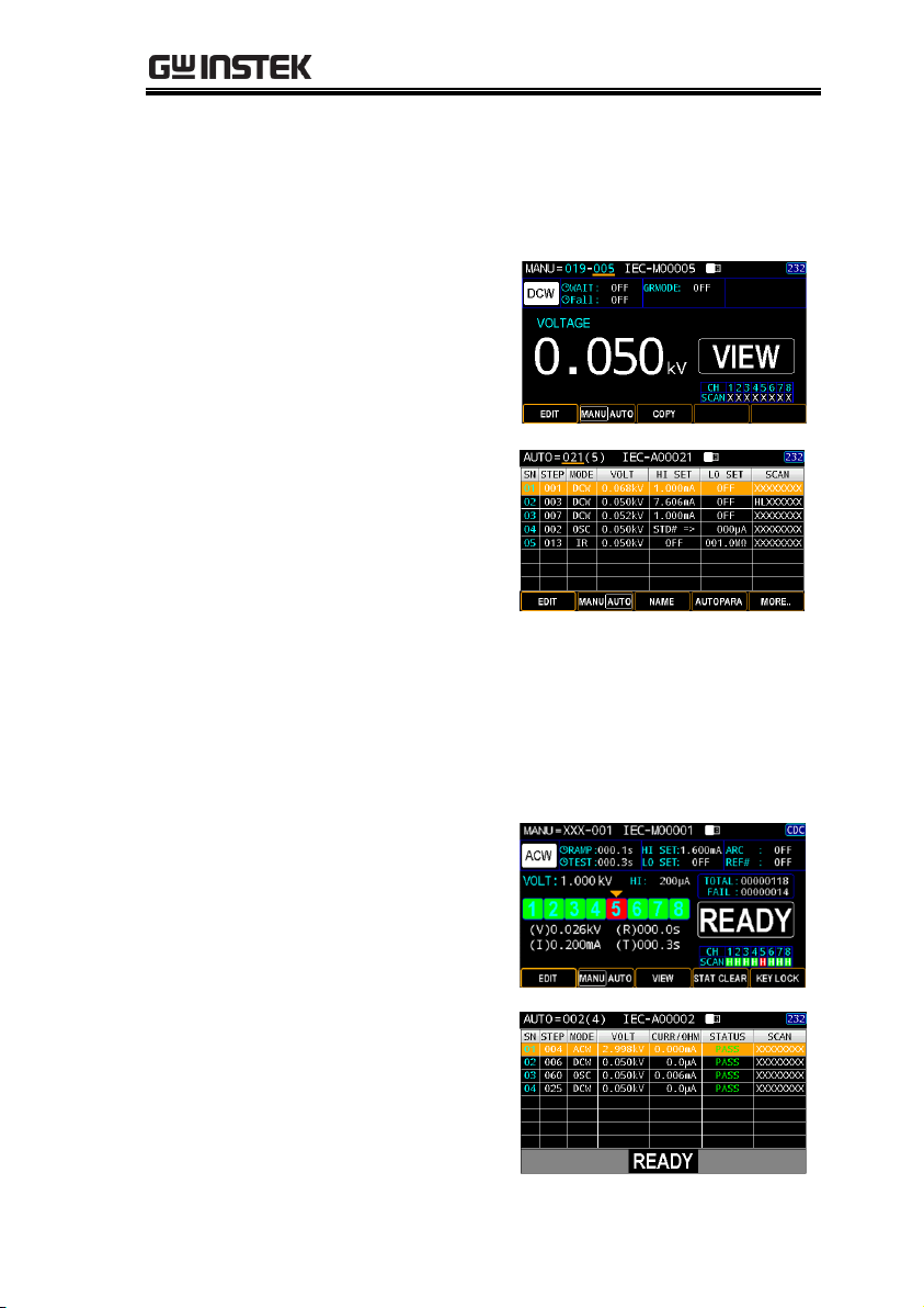
Page VIEW
for MANU
mode under
VIEW status
Page VIEW
for AUTO
mode under
VIEW status
Page View for
READY status
Under READY status, pressing PAGE key to
see measured values with judgments in detail
of each channel for MANU mode (only
available when scan function is enabled, refer
to page 55) or to see measured values with
judgments within a list table for AUTO mode.
Page VIEW
for MANU
mode under
READY status
Page VIEW
for AUTO
mode under
READY status
35

GPT-9500 Series User Manual
VIEW Status
VIEW status is used to view the parameters of the
selected MANU test/AUTO test. Also, pressing
the PAGE key under VIEW status can switch to
specific page view for MANU or AUTO mode.
VIEW status
in MANU
test
VIEW status
in AUTO
test
1
VIEW
EDIT Status
EDIT status is used to edit the MANU test or
AUTO test parameters. Pressing the
EDIT/SAVE key will save any changes.
Pressing the ESC key will cancel any changes.
EDIT status
in MANU
test
EDIT status
in AUTO
test
36

OPERATION
READY Status
When the tester is in READY status of MANU
or AUTO test, it is ready to begin testing.
Pressing the START button will begin testing
and put the tester into TEST status. Pressing the
MANU/AUTO soft-key will return the tester to
VIEW status. Also, pressing the PAGE key
under READY status can switch to specific
page view for MANU or AUTO mode.
READY
status in
MANU
test
READY
status in
AUTO
test
1
AUTO steps list – page 2
37

GPT-9500 Series User Manual
TEST Status
TEST status is active when a MANU test or
AUTO test is running. Pressing STOP will
cancel the MANU test or the remaining steps in
an AUTO test instantly.
TEST status
in MANU
test
TEST status
in AUTO
test
STOP Status
STOP status is shown when a MANU or an
AUTO test did not finish running and has been
stopped by user. Pressing STOP will return the
tester to READY status.
STOP status
in MANU
test
STOP status
in AUTO
test
38

OPERATION
Background
ACW, DCW and IR tests use the HIGH
VOLTAGE terminal and RETURN terminal
with the GHT-115 test leads.
ACW, DCW, IR
Connection
High Voltage terminal
DUT
GPT-9500
Return terminal
Steps
1. Turn the power off on the tester.
2. Connect the high voltage test lead (red) to the
HIGH VOLTAGE terminal and screw firmly
into place.
3. Connect the return test lead (white) into the
RETURN terminal and screw the protector bar
into place, as shown below.
HIGH
VOLTAGE
Terminal
RETURN
Terminal
Test Lead Connection
This section describes how to connect the GPT-9500 to a DUT for
ACW withstanding, DCW withstanding as well as insulation
resistance testing.
ACW, DCW, IR Connection
39

GPT-9500 Series User Manual
MANU Tests
This section describes how to create, edit and run ACW, DCW and
IR manual tests. Each MANU setting described in this chapter only
applies to the selected manual test – no other manual tests are
affected.
Each manual test can be stored/recalled to/from one of 501
memory locations. Each stored manual test can be used as a test
step when creating an AUTO test (page 90).
Choose/Recall a MANU Test Number → from page 41.
Setting the MANU Test Mode → from page 43.
Setting the Test Voltage → from page 44.
Setting the Ramp UP Time → from page 45.
Setting the Test Time → from page 47.
Setting the Upper and Lower Limits → from page 50.
Setting the ARC Detection → from page 52.
Setting a Reference Value → from page 53.
Setting the Scan Arrangement → from page 55.
Creating a MANU Test Name → from page 57.
Setting the Wait Time → from page 59.
Setting the Fall Time → from page 61.
Setting the Grounding Mode → from page 63.
Setting the IR Test Range → from page 66.
Setting OFFSET reference value → from page 67.
Viewing the Parameters Settings → from page 69.
Setting the Pause (PA) Step → from page 71.
Setting the Open Short Check (OSC) Step → from page 74.
Copy a MANU step → from page 77.
Clear the MANU tests state → from page 79.
Set the Panel Key Lock → from page 80.
Running a MANU Test → from page 82.
PASS / FAIL MANU Test → from page 86.
40

OPERATION
Background
AC Withstand (ACW), DC Withstand (DCW),
Insulation Resistance (IR), Pause (PA) and Open
Short Check (OSC) modes can only be created
and edited in the MANU mode. MANU number
001 to 500 can be saved and thus be loaded when
editing/creating a MANU test or an AUTO test.
MANU number 000 acts like a trial mode in that
it could not be added into AUTO test.
Steps
1. Press the MANU/AUTO soft-
key to select MANU option.
2. Use the scroll wheel to choose
the MANU number.
MANU #
000~500
(MANU# 000 acts like a trial mode)
Note
The MANU test number can only be chosen in
VIEW status.
MANU Number
Description
The following “MANU=XXX-019” stands for
the MANU step 019 of the AUTO group XXX.
The XXX simply means this MANU step
doesn’t belong to any AUTO group.
Choose/Recall a MANU Test Number
41

GPT-9500 Series User Manual
MANU step 019
AUTO group XXX
VIEW status
Note
When MANU step has been added to AUTO
group, the number of AUTO group shows in
the prefix (021 in the case below) and the full
MANU number turn out bluish.
MANU step 003 in bluish
AUTO group 021 in bluish
42

OPERATION
Background
Essentially, there are 5 modes, AC Withstand
(ACW), DC Withstand (DCW), Insulation
Resistance (IR), Pause (PA) and Open Short
Check (OSC) modes. Precisely, the previous 3
(ACW, DCW and IR) are for both MANU and
AUTO tests, whereas the rest 2 (PA and OSC)
are for AUTO test only.
Steps
1. Press the MANU/AUTO soft-
key to select MANU option.
2. Press the EDIT soft-key followed
by clicking the MODE soft-key.
3. Navigate the scroll wheel to
toggle between 5 modes. Further
press the SAVE soft-key to
confirm the selection.
ACW
DCW
IR
PA
OSC
AC Withstand (MANU, AUTO)
DC Withstand (MANU, AUTO)
Insulation Resistance (MANU, AUTO)
Pause action(AUTO)
Open Short Check action(AUTO)
Selected MANU Test Mode
4. Press the SAVE soft-key to complete.
Setting the MANU Test Mode
43

GPT-9500 Series User Manual
Background
The test voltage can be set from 0.050kV to 5kV
for ACW, 0.050kV to 6kV for DCW and 0.050kV
to 1kV for IR.
Steps
1. Press the MANU/AUTO soft-key
to select MANU option.
2. Press the EDIT soft-key followed
by clicking the VOLTAGE soft-key.
3. Use the scroll wheel to set the test
voltage.
ACW
DCW
IR
0.050kV ~ 5kV
0.050kV ~ 6kV
0.050kV ~ 1kV
Set the test voltage
4. Press the SAVE soft-key to complete.
Setting the Test Voltage
44

OPERATION
Background
The Ramp Up time is the total time taken for
the tester to reach the test voltage level. The
Ramp Up time can be set from 000.1 to 999.9
seconds. The Ramp Up time is applicable for
ACW, DCW and IR tests.
Output Voltage
Timing Chart
(Resistive load)
Test V
time
TEST TIME
RAMP UP
FALL
Steps
1. Press the MANU/AUTO soft-key
to select MANU option.
2. Press the EDIT soft-key followed by
clicking the RAMP TIME soft-key.
3. Use the scroll wheel to set the
ramp up time.
ACW
DCW
IR
000.1s~999.9s
000.1s~999.9s
000.1s~999.9s
Set the ramp up time
Setting the Ramp UP Time
45

GPT-9500 Series User Manual
4. Press the SAVE soft-key to complete.
Ramp Time
Duration
Indicator
After pressing START to begin MANU test with
set RAMP TIME, a section at the upper left
corner of display shows the countdown duration
of RAMP TIME, which will run for the full
course of set value followed by the set test time.
Ramp time duration indicator
46

OPERATION
Background
This setting is used to set the test time for a test.
The test time determines how long the test
voltage is applied to DUT. This test time does
not include RAMP UP time or FALL time. The
test time can be set from 0.3 seconds to 999.9
seconds for ACW, DCW and IR tests, with a
resolution of 0.1 seconds for all modes. Also, the
test time can be set “CONT.” for all 3 modes.
Output Voltage
Timing Chart
(Resistive load)
Test V
time
TEST TIME
RAMP UP
FALL
Steps
1. Press the MANU/AUTO soft-key
to select MANU option.
2. Press the EDIT soft-key followed by
clicking the TEST TIME soft-key.
3. Use the scroll wheel to set the
TEST TIMER value.
ACW
DCW
IR
000.3s~999.9s
000.3s~999.9s
000.3s~999.9s
Setting the Test Time
47

GPT-9500 Series User Manual
Set the test time
4. Press the SAVE soft-key to complete.
CONT. Test Time
When it is either ACW, DCW or IR test, the TEST
TIME can be set CONT., which means the test time
will last infinitely until FAIL judgment occurs.
Identical with the regular setting for
TEST TIME, use the scroll wheel to
set CONT. for TEST TIME value.
Test time is set CONT.
Note
When setting greater than 40VA for DCW and
greater than100VA for ACW, respectively, the
maximum test time is 600 seconds followed by the
identical rest time.
48

OPERATION
Test Time
Duration
Indicator
After pressing START to begin MANU test with
set TEST TIME, a section at the upper left corner
of display shows the countdown duration of set
TEST TIME following the end of set RAMP TIME.
Test time duration indicator
49

GPT-9500 Series User Manual
Background
There is both a LOW and HI judgment setting.
When the measured value is below the LOW
SET setting, the test will be judged as FAIL.
When the value exceeds the HI SET setting the
test will be judged as FAIL. Any measurement
between the LOW SET and HI SET setting is
judged as PASS. The LOW SET limit cannot be
made greater than the HI SET limit.
Steps
1. Press the MANU/AUTO soft-key
to select MANU option.
2. Press the EDIT soft-key followed by
clicking the PAGE key.
3. Press the HI/LO SET soft-key and
then use the scroll wheel to set the
HI SET limit.
ACW (HI)
DCW (HI)
IR (HI)
001μA~033.0mA
001μA~11.00mA
000.2MΩ~50.00GΩ, OFF
Set HI SET limit
Setting the Upper and Lower Limits
50

OPERATION
4. Press the HI/LO SET soft-key and
then use the scroll wheel to set the
LO SET limit.
ACW (LO)
DCW (LO)
IR (LO)
OFF, 001μA~32.99mA
OFF, 001μA~10.99mA
000.1MΩ~50.00GΩ
Set LO SET limit
5. Press the SAVE soft-key to complete.
Note
*Please note that the resolution of the measured
value depends on the resolution of HI SET setting.
Note
The LO SET setting is limited by the HI SET
setting. The LO SET limit cannot be greater than
the HI SET limit.
51

GPT-9500 Series User Manual
Background
ARC detection, otherwise known as flashover
detection, detects fast voltage or current transients
that are not normally detected. Arcing is usually
an indicator of poor withstanding insulation,
electrode gaps or other insulating problems that
cause temporary spikes in current or voltage
during ACW and DCW testing. ARC mode setting
only applies to both ACW and DCW tests.
Steps
1. Press the MANU/AUTO soft-key
to select MANU option.
2. Press the EDIT soft-key followed by
clicking the PAGE key.
3. Press the ARC/REF# soft-key and
then use the scroll wheel to set the
threshold of ARC detection.
ACW
DCW
OFF, 1.000mA~60.00mA
OFF, 1.000mA~60.00mA
Set ARC detection threshold
4. Press the SAVE soft-key to complete.
Setting the ARC Detection
52

OPERATION
Background
The REF# acts as an offset. The REF VALUE is
subtracted from the measured current (ACW,
DCW) or measured resistance (IR).
Steps
1. Press the MANU/AUTO soft-key
to select MANU option.
2. Press the EDIT soft-key followed by
clicking the PAGE key.
3. For both ACW and DCW modes,
press the ARC/REF# soft-key for
two times and then use the scroll
wheel to set the REF# value.
As for IR mode, press the REF#
soft-key followed by using the
scroll wheel to set the REF# value.
ACW
DCW
IR
OFF, 001μA~HI SET current-0.1mA
*HI SET + REF value ≤ 33.00 mA
OFF, 001μA~HI SET current-0.1mA
*HI SET + REF value ≤ 11.00 mA
OFF, 000.1MΩ~50.00GΩ
Setting a Reference Value
53

GPT-9500 Series User Manual
Set REF# value
4. Press the SAVE soft-key to complete.
Note
For IR test, an offset reference value of tester can
be automatically created via the GR MODE and
OFFSET functions. See page 67 for details.
54

OPERATION
Background
As an 8-channel output hipot tester, up to 8
DUTs can be connected and tested with this
tester simultaneously. Consequently, user is able
to customize own deployments for each channel
per varied applications.
There are 3 statuses available for each channel,
which are “X” meaning open or no connection,
“H” standing for Hi-POT & IR output and “L”
signaling Return terminal.
Steps
1. Press the MANU/AUTO soft-key
to select MANU option.
2. Press the EDIT soft-key followed by
clicking the PAGE key.
3. Press the SCAN soft-key to enter
the SCAN setting.
4. Use the left and right arrow keys to
move among each channel, and
utilize the scroll wheel to set the
status for each channel in light of
the practical applications.
H
L
X
Hi-POT/IR output
Return terminal
Open/No Connection
Note
Only GPT-9513 supports L-Return terminal setup.
The GPT-9503 is Not available for L setup.
Setting the Scan Arrangement
55

GPT-9500 Series User Manual
Set the SCAN arrangment
5. Press the SAVE soft-key to complete.
Scan Judgments
After performing a test, if the “Step By Step Scan
(page 179)” is activated, it is available to check
judgments of each channel from display where
green indicates the channels are passed, whilst red
indicates the channel is failed.
SCAN judgments after a test
Press the PAGE key and arrow keys to toggle scan
details of each channel where info of test voltage
(V), measured current (I), ramp up time (R) and
test time (T) are displayed, individually.
Judgment details of each channel
56

OPERATION
Note
When multiple channels are set “H”
simultaneously, it is required to apply to the DUTs
of identical property with total leaking current
composed of the total amount from each channel.
And properly adjust the set current value while
considering the leaking current change from each
DUT. Be aware that there is certain degree of
uncertainty from this test. Be advised to
manipulate multi-channels output test when DUTs
are of high yield rate and stability.
Background
Each MANU test can have a user-defined name
(default: IEC-M00XXX) up to 13 characters
long. See the available list of characters below.
Character List
Steps
1. Press the MANU/AUTO soft-key
to select MANU option.
2. Press the EDIT soft-key followed by
clicking the PAGE key.
3. Press the NAME soft-key to enter
the NAME setting.
Creating a MANU Test Name
57

GPT-9500 Series User Manual
4. The on-screen keyboard is shown where user
can input a preferred name for MANU test. Use
the arrow keys or scroll wheel to move among
each character and press INPUT soft-key to
input character. Press CAPSLOCK soft-key to
toggle between high and low case. Press
BACKSPACE soft-key to backspace the
inputted word. Press EXIT KeyB to exit from
the KeyBoard and discard setting.
On-screen Keyboard
Functional Soft-keys
5. Press the OK soft-key to confirm
input followed by pressing the
SAVE soft-key to complete setting.
58

OPERATION
Background
The Wait Time refers to the pending time
before judgment appears. Generally, test time
begins after ramp up time; however, a wait
time can be intervened between ramp up time
and test and begins depending on relevant
settings. See page 159 for details.
The Wait Time is applicable for ACW, DCW
and IR tests.
Steps
1. Press the MANU/AUTO soft-key
to select MANU option.
2. Press the EDIT soft-key followed by
clicking the PAGE key for twice.
x 2
3. Press the WAIT TIME soft-key
followed by using the scroll wheel
to set the WAIT TIME value.
ACW
DCW
IR
OFF, 000.1s~999.9s
OFF, 000.1s~999.9s
OFF, 000.1s~999.9s
Setting the Wait Time
59

GPT-9500 Series User Manual
Set the WAIT time value
4. Press the SAVE soft-key to complete.
Wait Time
Indicator
When performing MANU test, while the WAIT time
is set, the indicator of WAIT time will be shown on
the upper right corner of display counting down
the set duration during a test progress.
WAIT time duration indicator
60

OPERATION
Background
The FALL time is the time taken for the DUT to
discharge the test voltage level. The FALL time
can be set from OFF to 999.9 seconds. The FALL
time is applicable for ACW, DCW and IR tests.
Output Voltage
Timing Chart
(Resistive load)
Test V
time
TEST TIME
RAMP UP
FALL
Steps
1. Press the MANU/AUTO soft-key
to select MANU option.
2. Press the EDIT soft-key followed by
clicking the PAGE key for twice.
x 2
3. Press the FALL TIME soft-key
followed by using the scroll wheel
to set the FALL TIME value.
ACW
DCW
IR
OFF, 000.1s~999.9s
OFF, 000.1s~999.9s
OFF, 000.1s~999.9s
Setting the Fall Time
61

GPT-9500 Series User Manual
Set the Fall time value
4. Press the SAVE soft-key to complete.
FALL Duration
Indicator
When performing MANU test, after the set
TEST TIME is fully completed, a section at the
upper right corner of display shows the
countdown duration of FALL time, which will
run for the full course of set value by user. See
the screenshot shown below.
Fall time duration indicator
62

OPERATION
Background
When GROUND MODE is set to ON, the GPT9500 grounds the return terminal to the ground.
This mode is best for DUTs that are grounded
to an earth ground by their chassis, fixtures or
operation environment. This mode measures
the potential of the HIGH VOLTAGE terminal
with respect to earth ground. This means that
any stray capacitance/resistance that leaks to
earth ground will also be measured. This is the
safest testing mode, though potentially not as
accurate.
When GROUND MODE is set to OFF, the
return terminal is floating with respect to the
earth ground. This mode is for DUTs that are
floating and not directly connected to an earth
ground. This is more accurate than when
GROUND MODE is set to ON as any stray
capacitance/resistance that leaks to the earth
ground from the DUT side of the testing circuit
will not be measured. For this reason, this
testing mode is able to measure to a higher
resolution.
GROUND MODE = ON, DUT grounded
High Voltage terminal
Return terminal
DUT
GPT-9500
stray
resistance,
capacitance
Setting the Grounding Mode
63

GPT-9500 Series User Manual
GROUND MODE = ON, DUT floating
High Voltage terminal
DUT
GPT-9500
stray
resistance,
capacitance
Return terminal
GROUND MODE = OFF, DUT floating
High Voltage terminal
DUT
GPT-9500
stray
resistance,
capacitance
Return terminal
GROUND MODE = OFF, DUT grounded
High Voltage terminal
DUT
GPT-9500
stray
resistance,
capacitance
Return terminal
Warning
When GROUND MODE is set to OFF, the DUT,
fixtures or connected instrumentation cannot be
grounded. This will short circuit the internal
circuitry during a test.
For ACW and DCW tests, if it is not known whether
the DUT test setup is grounded or not, always set
GROUND MODE to ON.
Only set GROUND MODE to OFF when the DUT
is floating electrically.
64

OPERATION
Steps
1. Press the MANU/AUTO soft-key
to select MANU option.
2. Press the EDIT soft-key followed by
clicking the PAGE key for twice.
x 2
3. Press the GR MODE soft-key
followed by using the scroll wheel
to turn ON/OFF the ground mode.
GR MODE
ON, OFF
Define GR mode
4. Press the SAVE soft-key to complete.
Ground mode
icon
The GR MODE icon on the display appears
accordingly.
GR MODE ON
GR MODE OFF
65

GPT-9500 Series User Manual
Background
Due to the measured current range in IR test is
way to broader per varied DUT, it is suggested
to select an appropriate current range for the
applied DUT. This is only available for IR test.
Steps
1. Press the MANU/AUTO soft-key
to select MANU option.
2. Press the EDIT soft-key followed by
clicking the PAGE key for twice.
x 2
3. Press the RANGE soft-key followed
by using the scroll wheel to set the
current range.
RANGE
5μA, 50μA, 500μA, 5mA, AUTO
Set the current RANGE
4. Press the SAVE soft-key to complete.
Setting the IR Test Range
66

OPERATION
Background
The OFFSET is used to determine the offset
resistance of the tester. It is imperative to turn
ON GR MODE before setting OFFSET value.
When an OFFSET is performed, the reference is
automatically set to the measured resistance.
This function is only applicable to IR test.
Steps
1. Press the MANU/AUTO soft-key
to select MANU option.
2. Press the EDIT soft-key followed by
clicking the PAGE key three times.
x 3
3. Press the OFFSET soft-key followed
by using the scroll wheel to turn
ON/OFF the OFFSET function.
OFFSET
ON, OFF
Turn ON OFFSET
4. Press the SAVE soft-key to complete.
Setting OFFSET reference value
67

GPT-9500 Series User Manual
5. Press the START button to perform
the OFFSET function. The
resistance of the tester, after the
OFFSET has finished, will be
added into the OFFEST field with
an icon in proximity shown below.
OFFSET reference is set
OFFSET CLEAR
It is available to clear the set
OFFSET reference value by
clicking the OF CLEAR soft-key.
The OFFSET icon will be disappeared meaning no
offset reference is set and the OF CLEAR soft-key
will be grayed out accordingly.
OFFSET reference is cleared
OF CLEAR soft-key is grayed out
68

OPERATION
Background
After setting up the parameters of each test
mode (ACW, DCW and IR), user can check
those settings anytime with ease.
Steps
1. Press the MANU/AUTO soft-key
to select MANU option.
2. Use the scroll wheel to go to the
target MANU step.
3. The parameters settings from each
test mode are shown below. Use
the PAGE key to toggle pages.
DCW
DCW parameters – page 1
DCW parameters – page 2
Viewing the Parameters Settings
69

GPT-9500 Series User Manual
ACW
ACW parameters – page 1
ACW parameters – page 2
IR
IR parameters – page 1
IR parameters – page 2
70

OPERATION
Background
Basically, Pause (PA) step under MANU mode
is specifically for AUTO mode. It provides,
based on differed applications, a pause action,
which is equivalent to an interval, within
AUTO group. User is able to define some
parameters for the set PA step.
Steps
1. Press the MANU/AUTO soft-
key to select MANU option.
2. Press the EDIT soft-key followed
by clicking the MODE soft-key.
3. Use the scroll wheel to select the
PA option.
4. Press the TIME soft-key followed
by using the scroll wheel to
define a time period in which PA
step will be shown on screen.
TIME
CONT.: Infinite time until START key
000.3s~999.9s
Set the TIME period
Setting the Pause (PA) Step
71

GPT-9500 Series User Manual
5. Press the MESSAGE soft-key to
enter the Message setting, which will
be shown when PA step endures.
6. The on-screen keyboard is shown where user
can input a preferred Message for PA. Use the
scroll wheel to move among each character and
press INPUT soft-key to input character. Press
CAPSLOCK soft-key to toggle between high
and low case. Press BACKSPACE soft-key to
backspace the inputted word. Press EXIT KeyB
to exit from the KeyBoard and discard setting.
On-screen Keyboard
Functional Soft-keys
7. Press the OK soft-key to confirm.
8. Press the SIGNAL soft-key
followed by using the scroll wheel
to turn ON/OFF Signal function,
which outputs signal information
including waveform of PA step to
the connected external instrument.
SIGNAL
ON, OFF
72

OPERATION
Turn ON/OFF SIGNAL
9. Press the SAVE soft-key to complete.
PA Display
While performing AUTO test where PA step is
added, the screen will be shown as follows for
PA step in which PAUSE TIME starts counting
and the defined MESSAGE is clearly shown.
The counting time for PA step
User-defined MESSAGE PA mode display
73

GPT-9500 Series User Manual
Background
Open Short Check (OSC) is a MANU step used
to define the thresholds when open circuit or
short circuit occurs between the test leads and
DUT. The section here allows user to assign Hi
limit and Low limit for Short and Open status
check, respectively.
OSC, identical with the PA step, is specifically
for AUTO mode. It provides an Open Short
check step for multiple channels based on
differed applications for AUTO tests.
Steps
1. Press the MANU/AUTO soft-
key to select MANU option.
2. Press the EDIT soft-key followed
by clicking the MODE soft-key.
3. Use the scroll wheel to select the
OSC option.
4. Press the OPEN soft-key
followed by using the scroll
wheel to define a percentage of
OPEN status judgment.
OPEN
10% ~ 100%
Setting the Open Short Check (OSC) Step
74

OPERATION
Set the OPEN ratio
5. Press the SHORT soft-key
followed by using the scroll
wheel to define a percentage of
SHORT status judgment.
SHORT
OFF, 100% ~ 500%
Set the SHORT ratio
6. Press the SCAN soft-key to enter
the SCAN setting.
7. Use the left and right arrow keys to
move among each channel, and
utilize the scroll wheel to set the
status for each channel in light of
the practical applications.
75

GPT-9500 Series User Manual
H
L
X
Hi-POT/IR output
Return terminal
Open/No Connection
Set the SCAN arrangment
8. Press the SAVE soft-key to complete.
OSC Display
Prior to executing OSC action, it is required to
get a STD value, for which refer to the page 111.
While performing AUTO test where OSC step
is added, the screen will be shown as follows
for OSC step in which FAIL judgments occurs
in that either measured current value is lower
than the set OPEN ratio or is higher than the
SHORT ratio. In the case below, OPEN
judgment comes up due to the measured
current is lower than the OPEN threshold of
user-defined 100% relative to the STD value.
OPEN status judgment
FAIL judgment
The user-defined OPEN & SHORT ratios
76

OPERATION
Background
In order promptly duplicate a MANU step,
follow the steps below for easy setup.
Steps
1. Make sure the unit is within the VIEW status
under MANU mode. If it is under READY
status, press the VIEW soft-key to return to the
VIEW status. Alternatively, if it is under the
EDIT status, press the SAVE soft-key to return
to the VIEW status.
COPY soft-key VIEW status
2. Use the scroll wheel to select a
source MANU step number (000
for example) and press the COPY
soft-key.
3. Further use the scroll wheel to
select a target MANU step
number (002 for example) and
press the PASTE soft-key.
Copy a MANU step
77

GPT-9500 Series User Manual
MANU step
000 is copied
PASTE soft-key
The MANU step number 000, from the example
above, is replicated to the MANU step number
002 successfully.
MANU step 002 has the identical
parameters with MANU step 000
78

OPERATION
Background
The state covering TOTAL test counts and
judgments of FAIL is clearly shown on the
READY status. To erase the records, follow the
steps below.
Steps
1. Make sure the unit is within the READY status.
If it is under VIEW status, press the STOP key
to return to the READY status. Alternatively, if
it is under the EDIT status, press the SAVE softkey followed by the STOP key to return to the
READY status.
READY status
State
table
TOTAL
FAIL
The total test counts
The total FAIL judgments
2. Press and hold the STAT CLEAR
soft-key for 1 second.
The tests state is zeroing
Clear the tests state
79

GPT-9500 Series User Manual
Background
Key Lock disables the front panel keys from
changing the test number, mode or testing
parameters. Only the START & STOP buttons
required for testing are not disabled. Also, the
KEY LOCK soft-key remains functional for user
to unlock the function.
Steps
1. Make sure the unit is within the READY status
under MANU mode. If it is under VIEW status,
press the STOP key to return to the READY
status. Alternatively, if it is under the EDIT
status, press the SAVE soft-key followed by the
STOP key to return to the READY status.
READY status KEY LOCK soft-key
2. Press and hold the KEY LOCK
soft-key for 1 second.
All soft-keys are disabled except for KEY LOCK
KEY LOCK icon is shown
Set the Panel Key Lock
80

OPERATION
Unlock Key Lock
1. Again, press and hold the KEY
LOCK soft-key for 1 second.
Functional Soft-keys
2. The on-screen keyboard is shown where user
can input password to unlock the key lock. Use
the scroll wheel to move among each number
and press INPUT soft-key to input number.
Press BACKSPACE soft-key to backspace the
inputted word. Press EXIT PW to exit from the
KeyBoard and discard setting.
3. Press the OK soft-key to unlock the
KEY LOCK function.
Note
The password by default is 12345678.
81

GPT-9500 Series User Manual
Background
A test can be run when the tester is in the
READY status.
Note
The tester cannot start to run a test under the
following conditions:
A protection setting has been tripped; when a
protection setting has been tripped the
corresponding error message is displayed on
the screen. See page 274 for a comprehensive
list of the all the setting errors.
The INTERLOCK function is ON and the
Interlock wire is not shorted in the Interlock
terminal (page 194).
The STOP signal has been received remotely.
If Double Action is ON, ensure the START
button is pressed immediately after the STOP
button (<0.5s).
Steps
1. Ensure the tester is in READY
status for the test to come.
Page 37
READY status
Running a MANU Test
82

OPERATION
2. Press the START button when the
tester is in the READY status. The
manual test starts accordingly and
the tester goes into the TEST status.
TEST status
3. The test will start by showing the ongoing
RAMP time followed by ongoing WAIT time
and the ongoing TEST time and, finally, the
ongoing FALL time. The test will continue until
the test is finished or stopped.
Ongoing
RAMP
time
Ongoing
TEST
time
Ongoing
WAIT
time
Ongoing
FALL
time
ACW Example
Test Voltage Measured Current
83

GPT-9500 Series User Manual
DCW Example
Test Voltage Measured Current
IR Example
Test Voltage Measured Resistance
Note
WAIT and FALL time only appear when user has
activated them. See page 61 and 48 for details.
Stop the Test
1. To stop the test at any time when it
is running, press the STOP button.
The test will stop immediately.
When the STOP button is pressed,
a judgment is not made and the
STOP status will be shown.
STOP status
84

OPERATION
2. Further press the STOP button
again to return to the READY
status.
Or press the START button to
resume the test.
Note
Do not touch any terminals, test leads or any other
connections when the test is ongoing.
85

GPT-9500 Series User Manual
Background
If the test is allowed to run to completion (the
test is not stopped or a protection setting is not
tripped) then the tester will judge the test as
either PASS or FAIL.
Note
The test will be judged PASS when:
The HI SET and LO SET limits have not been
tripped during the test time.
The test will be judged FAIL when:
Either the HI SET or LO SET limit has been
tripped during the test time.
A protection setting has been tripped during
the test time. See page 274 for a list of error
messages.
PASS Judgment
1. When the test is judged as PASS,
PASS will be displayed on screen,
the buzzer will sound and the
PASS indicator will be lit green.
PASS judgment
PASS / FAIL MANU Test
86

OPERATION
2. The tester will immediately restore back to the
READY status after PASS judgment. However,
if the PASS HOLD is activated, PASS judgment
will persist until the set duration of PASS
HOLD is fully met. Refer to page 82 for details.
In addition, pressing the STOP
button during the set duration of
PASS HOLD can return to READY
status immediately.
Note
The buzzer will only sound if the Buzzer is set to
ON. See page 142 for details.
PASS Timing
Diagrams
The timing diagrams below show the ACW, DCW
and IR timing for the START status, TEST status
and PASS judgment.
ACW PASS
Timing
FALL TIME
& DISCHARGE
Output V
time
START
TEST
PASS
RAMP UPTEST TIME
DCW PASS
Timing
Output V
time
START
TEST
PASS
RAMP UPTEST TIME
FALL TIME
& DISCHARGE
87

GPT-9500 Series User Manual
IR PASS Timing
Output V
time
START
TEST
PASS
RAMP UPTEST TIME
FALL TIME
& DISCHARGE
FAIL Judgment
1. When the test is judged as FAIL,
FAIL will be displayed on screen,
the buzzer will sound and the
FAIL indicator will be lit red.
As soon as a test is judged FAIL,
power is cut from the terminals.
FAIL judgment
2. The FAIL judgment will be held on
the display until the STOP button
is pressed. Pressing the STOP
button will return the tester back to
the READY status.
Or press the START button to
resume the test.
Note
The buzzer will only sound if Fail Sound is set to
ON. See page 142 for details.
88

OPERATION
FAIL Timing
Diagrams
The timing diagrams below show the ACW, DCW
and IR timing for the START status, TEST status
and FAIL judgment.
ACW FAIL Timing
DISCHARGE
Output V
time
START
TEST
FAIL
RAMP UPTEST TIME
DCW FAIL Timing
DISCHARGE
Output V
time
START
TEST
FAIL
RAMP UPTEST TIME
IR FAIL Timing
DISCHARGE
Output V
time
START
TEST
FAIL
RAMP UPTEST TIME
89

GPT-9500 Series User Manual
AUTO Tests
This section describes how to create, edit and run up to 100
automatic tests. An Automatic test allows you to group up to 99
different MANU tests and run them sequentially within a single
AUTO test. Each stored MANU test is used as a test step when
creating an AUTO test.
Choose/Recall an AUTO Test→ from page 91
Creating an AUTO Test Name → from page 92
Adding a MANU Step to the AUTO Test → from page 93
Viewing and Editing AUTO Group → from page 94
Setting AUTO Parameters → from page 96
Getting the Reference Value → from page 109
Getting the Standard Value → from page 111
Viewing Steps in AUTO Group → from page 113
Viewing Parameters Settings of Each Step in List → from page 115
Page View in AUTO Test → from page 116
Clear the AUTO tests state → from page 119
Set a Panel Key Lock → from page 120
Running an Automatic Test → from page 122
AUTO Test Results → from page 133
Before operating the GPT-9500 please read the safety precautions as
outlined in the Set Up chapter on page 21.
90

OPERATION
Background
The tester must first be put into AUTO mode to
create or run automatic tests. Up to 100
automatic tests can be saved or recalled.
Steps
1. Press the MANU/AUTO soft-key
to select AUTO option.
2. Use the scroll wheel to select a
number of AUTO group.
AUTO #
000~099
Note
The AUTO group number can only be chosen
in VIEW status. And the AUTO 000 group is
specifically for remote control usage.
AUTO Group
Number
Description
The following “AUTO = 000 (0)” stands for the
AUTO group 000 where zero (0) MANU step is
added.
Total MANU steps
being added
AUTO group number
VIEW status
Choose/Recall an AUTO Test
91

GPT-9500 Series User Manual
Background
Each AUTO test can have a user-defined test
name (Default: IEC-A000XX) up to 13 characters
long. See the available list of characters below.
Character List
Steps
1. Press the MANU/AUTO soft-key
to select AUTO option.
2. Press the NAME soft-key to enter
the NAME setting.
3. The on-screen keyboard is shown where user
can input a preferred name for AUTO test. Use
the arrow keys or scroll wheel to move among
each character and press INPUT soft-key to
input character. Press CAPSLOCK soft-key to
toggle between high and low case. Press
BACKSPACE soft-key to backspace the
inputted word. Press EXIT KeyB to exit from
the KeyBoard and discard setting.
Creating an AUTO Test Name
92

OPERATION
On-screen Keyboard
Functional Soft-keys
4. Press the SAVE soft-key to confirm
the input name.
Background
Up to 99 MANU steps can be added to an AUTO
test. Each step is added in a sequential order.
Steps
1. Press the MANU/AUTO soft-key
to select AUTO option.
2. Press the EDIT soft-key.
3. Use the scroll wheel to choose
target MANU step(s) to be added
to the AUTO test.
4.
MANU STEP number
001~500
Adding a MANU Step to the AUTO Test
93

GPT-9500 Series User Manual
The selected MANU step number
ADD(x) soft-key
Note
When MANU step has been added to AUTO
group, the number of MANU step turn out
bluish and thus will be Not added again.
MANU number 000 acts like a trial mode in that
it could Not be added into AUTO test.
4. Press the ADD(x) soft-key to add
the selected MANU step into the
AUTO group.
Note
The (x) behind ADD soft-key signifies the total
MANU steps being added into the AUTO group.
5. Repeat the previous steps for any other MANU
tests that you wish to add to the AUTO test.
Background
View contents of AUTO group in a table list
where user can execute several actions to
compose the AUTO group.
Steps
1. Press the MANU/AUTO soft-key
to select AUTO option.
Viewing and Editing AUTO Group
94

OPERATION
2. Press the VIEW soft-key to enter
the table page.
List of MANU steps of AUTO group
Functional Soft-keys
Delete MANU
Step
3. Use the scroll wheel to move to
each MANU step. Press DELETE
soft-key to remove MANU step
from the table or press DEL ALL
to remove the entire MANU steps.
Insert MANU
Step
4. Use the scroll wheel to move to
each MANU step. Press INSERT
soft-key to enter the next page.
5. From the screen below, use the
scroll wheel to move to each
MANU step followed by pressing
INSERT soft-key to add target
MANU step into the AUTO list.
Press the RETURN soft-key to
discard insert action.
95

GPT-9500 Series User Manual
Selected target MANU step
Functional Soft-keys
Note
When MANU step has been added to AUTO
group, the number of MANU step turn out
bluish and thus will be Not added again.
6. Press the EXIT soft-key to leave from
the AUTO table list.
Background
This is the parameters setting page specific for
AUTO test. It has the higher authority over the
parameter settings of each MANU step. Each
AUTO group has its own AUTO parameters,
which are commonly shared by all MANU
steps within the same AUTO group.
Steps
1. Press the MANU/AUTO soft-
key to select AUTO option.
2. Press the AUTOPARA soft-key
to enter the AUTO parameters.
Setting AUTO Parameters
96

AUTO
Parameters
Settings
PASS HOLD
Background
The PASS HOLD setting refers to the holding
duration after PASS judgment is shown on the
display. When the PASS HOLD setting is set, a
PASS judgment is held until the set duration is
fully reached.
1. Use the PREV & NEXT keys or
scroll wheel to move to the PASS
HOLD field.
2. Press the ENTER soft-key followed
by using the arrow keys and scroll
wheel to define a duration.
PASS HOLD
000.2s ~ 999.9s
3. Press the ENTER soft-key to
confirm the setting
Note
The STOP key can be pressed at any time in the set
duration of PASS HOLD to promptly halt the set
PASS HOLD duration.
OPERATION
97

STEP HOLD
Background
The STEP HOLD setting refers to the holding
duration after each step within a AUTO group
1. Use the PREV & NEXT keys or
scroll wheel to move to the STEP
HOLD field.
2. Press the ENTER soft-key followed
by using the scroll wheel to select
an option. When TIME is selected,
define an H-TIME by using the
arrow keys and the scroll wheel.
TIME
Step is held until the set duration (HTIME) is reached. 000.2 ~ 999.9 sec
KEY
Step is held until the START key is
pressed.
3. Press the ENTER soft-key to
confirm the setting
Note
The STOP key can be pressed at any time in the set
duration of STEP HOLD to promptly halt the set
STEP HOLD duration.
GPT-9500 Series User Manual
98

AFTER FAIL
Background
The AFTER FAIL setting refers to the ensuing action
after FAIL judgment is shown on the display.
1. Use the PREV & NEXT keys or
scroll wheel to move to the AFTER
FAIL field.
2. Press the ENTER soft-key followed
by using the scroll wheel to select
an option.
CONT.
Next step keeps going even after
FAIL judgment appears.
STOP
AUTO test will be stopped
immediately after FAIL judgment of
one of the steps appears. Only the
STOP key can be pressed to return
to the READY status.
RESTART
AUTO test will be stopped
immediately after FAIL judgment of
one of the steps appears. User can
press START key to restart the
AUTO test from the 1st step.
3. Press the ENTER soft-key to
confirm the setting
OPERATION
99

AC FREQ
Background
A test frequency of 60Hz or 50Hz can be set,
regardless of the input line voltage. The test
frequency setting only applies to ACW test.
1. Use the PREV & NEXT keys or
scroll wheel to move to the AC
FREQ field.
2. Press the ENTER soft-key followed
by using the scroll wheel to select
an option.
AC FREQ
50Hz, 60Hz
3. Press the ENTER soft-key to
confirm the setting
Background
In theory, neither PASS nor FAIL status is
judged during the ramp up time. However,
RAMP JUDG. enables judgment during the
ramp up duration instead for certain application.
1. Use the PREV & NEXT keys or
scroll wheel to move to the RAMP
JUDG. field.
GPT-9500 Series User Manual
RAMP JUDG.
100
 Loading...