

MULTI-OUTPUT POWER SUPPLY
MULTI-OUTPUT POWER SUPPLY
USER MANUAL
USER MANUAL
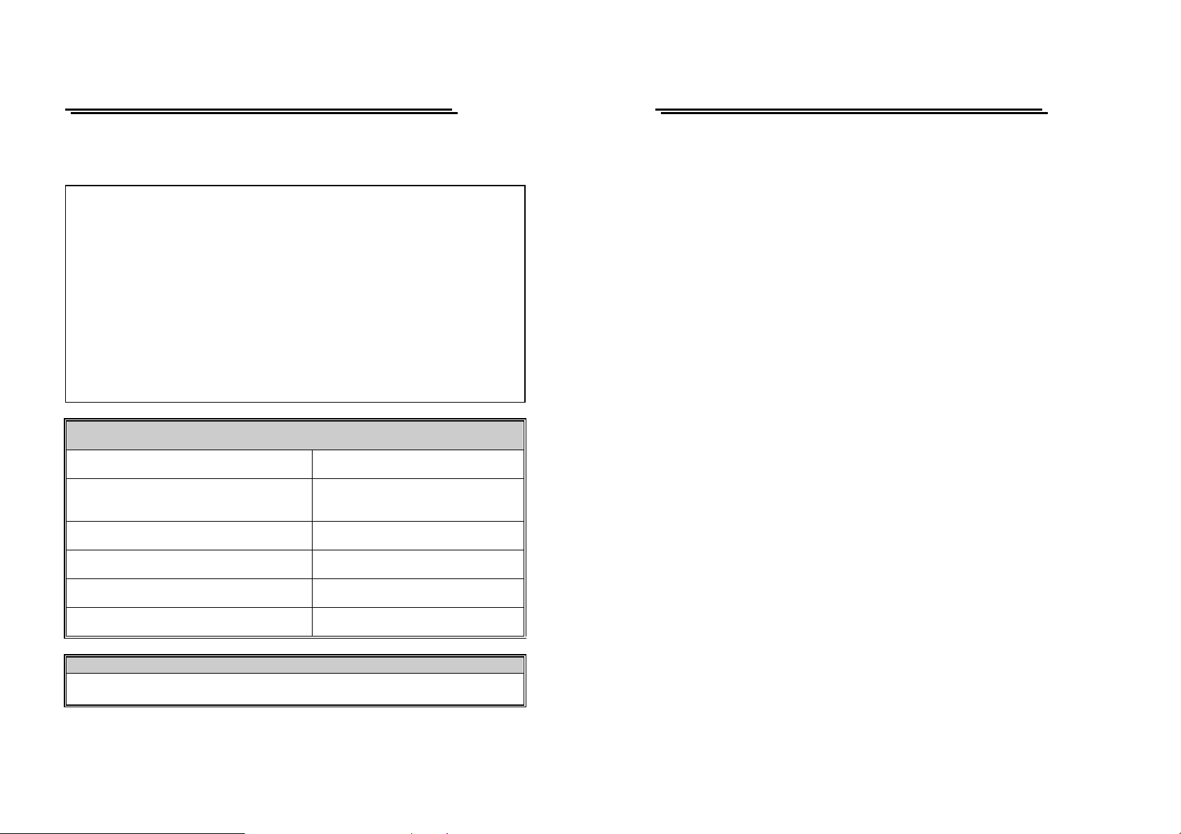
Declaration of Conformity
We
GOOD WILL INSTRUMENT CO., LTD.
No. 95-11, Pao-Chung Rd., Hsin-Tien City, Taipei Hsien, Taiwan
GOOD WILL INSTRUMENT (SUZHOU) CO., LTD.
No.69 Lushan Road, Suzhou New District Jiangsu, China.
declares that the below menti one d products
GPS-2303/3303/4303/4302
are herewith confirmed to comply with the requirements set out in the Council
Directive on the Approximation of the Law of Member States relating to
Electromagnetic Compatibility (89/336/EEC, 92/31/EEC, 93/68/EEC) and
Low Voltage Equipment Directive (73/23/EEC).
For the evaluation regarding the Electromagnetic Compatibility and Low
Voltage Equipment Directive, the following standards were applied:
◎ EMC
EN 61326-1: Electrical equipment for measurement, control and laboratory
use –– EMC requirements (1997+A1: 1998)
Conducted and Radiated Emissions
EN 55011: 1998
Current Harmonic
EN 61000-3-2:
1995+A1: 1998+A2: 1998 +A14: 2000
Voltage Fluctuation
EN 61000-3-3: 1995
-------------------------
-------------------------
-------------------------
◎ Safety
Low Voltage Equipment Directive 73/23/EEC & amended by 93/68/EEC
EN 61010-1 : 2001
IEC 61010-1: 2001
Electrostatic Discharge
EN 61000-4-2: 1995+A1:1998
Radiated Immunity
EN 61000-4-3: 1996+A1:1998
Electrical Fast Transients
EN 61000-4-4: 1995
Surge Immunity
EN 61000-4-5: 1995
Conducted Susceptibility
EN 61000-4-6: 1996
Voltage Dips/ Interrupts
EN 61000-4-11: 1994
i
i
MULTI-OUTPUT POWER SUPPLY
MULTI-OUTPUT POWER SUPPLY
USER MANUAL
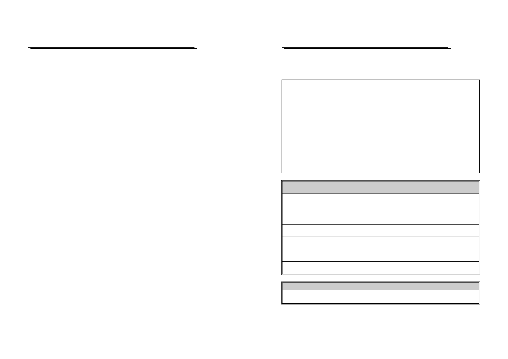
Declaration of Conformity
We
GOOD WILL INSTRUMENT CO., LTD.
No. 95-11, Pao-Chung Rd., Hsin-Tien City, Taipei Hsien, Taiwan
GOOD WILL INSTRUMENT (SUZHOU) CO., LTD.
No.69 Lushan Road, Suzhou New District Jiangsu, China.
declares that the below menti one d products
GPS-4251(GPQ-2505D)
are herewith confirmed to comply with the requirements set out in the Council
Directive on the Approximation of the Law of Member States relating to
Electromagnetic Compatibility (89/336/EEC, 92/31/EEC, 93/68/EEC) and
Low Voltage Equipment Directive (73/23/EEC).
For the evaluation regarding the Electromagnetic Compatibility and Low
Voltage Equipment Directive, the following standards were applied:
◎ EMC
EN 61326-1: Electrical equipment for measurement, control and laboratory
use –– EMC requirements (1997+A1: 1998)
Conducted and Radiated Emissions
EN 55011: 1991+A1: 1997+A2: 1998
Current Harmonic
EN 61000-3-2:
1995+A1: 1998+A2: 1998 +A14: 2000
Voltage Fluctuation
EN 61000-3-3: 1995
-------------------------
-------------------------
-------------------------
◎ Safety
Low Voltage Equipment Directive 73/23/EEC & amended by 93/68/EEC
EN 61010-1 : 1993+A2 :1995
IEC 1010-1: 1990+A2 :1995
Electrostatic Discharge
EN 61000-4-2: 1995
Radiated Immunity
EN 61000-4-3: 1996+A1:1998
Electrical Fast Transients
EN 61000-4-4: 1995
Surge Immunity
EN 61000-4-5: 1995
Conducted Susceptibility
EN 61000-4-6: 1996
Voltage Dips/ Interrupts
EN 61000-4-11: 1994
USER MANUAL
SECTION PAGE
1. INTRODUCTION........…………………………………………… 1
2. SPECIFICATIONS……………………………………………......
2-1 General…………………………………………………………
2-2 Operation Mode……………………………………………….
2-3 Constant Voltage Operation………………… ……… ……….
2-4 Constant Current Operation………………………………….
2-5 Tracking Mode……………………………………… ……… ...
2-6 Meter…………………………………………………………...
2-7 CH3 Output Specification…………………………………….
2-8 CH4 Output Specification…………………………………….
2-9 Insulation………………………………………………………
3. THEORY OF OPERATION..………………… ……… ……. ....... 4
4. PANEL CONTROLS AND INDICATORS....... .. ..…… ……… …
4-1 Front Panel…………………………………………………….
4-2 Real Panel……………………………………………………...
5. OPERATION INSTRUCTION…………………….……….........
5-1 Precaution……………………………………………………...
5-2 Setting Current Limit…………………………………………
5-3 Constant Voltage/ Constant Curre nt Ch ar acteri stic ……… ..
5-4 Operation Mode……………………………………………….
6. MAINTENANCE…......………………………… ……… …….......
6-1 Fuse Replacement……………………………………………..
6-2 Line Voltage Conversion……………………………………...
6-3 Adjustments……………………………………………………
6-4 Cleaning………………………………………………………..
2
2
2
2
3
3
3
3
3
4
6
8
10
11
11
11
12
13
19
19
19
20
24
ii
iii
MULTI-OUTPUT POWER SUPPLY
USER MANUAL
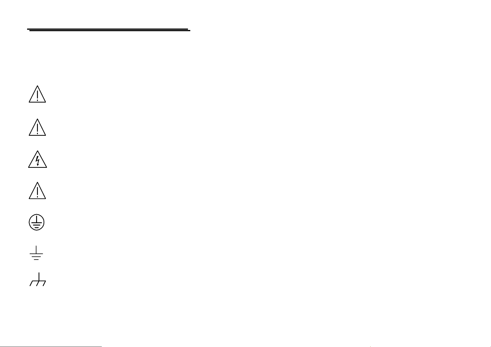
SAFETY TERMS AND SYMBOLS
Please take a moment to review these safety terms and symbols which may
appear in this manual or on Equipment to prevent damage to the Function
Generators.
WARNING. Warning statements identify condition or practices
that could result in injury or loss of life.
CAUTION. Caution statements identify conditions or practices
that could result in damage to this product or other property.
DANGER High Voltage
ATTENTION refer to Manual
Protective Conductor Terminal
(ground) Earth Terminal
Frame or Chassis Terminal
iv
MULTI-OUTPUT POWER SUPPLY
MULTI-OUTPUT POWER SUPPLY
USER MANUAL
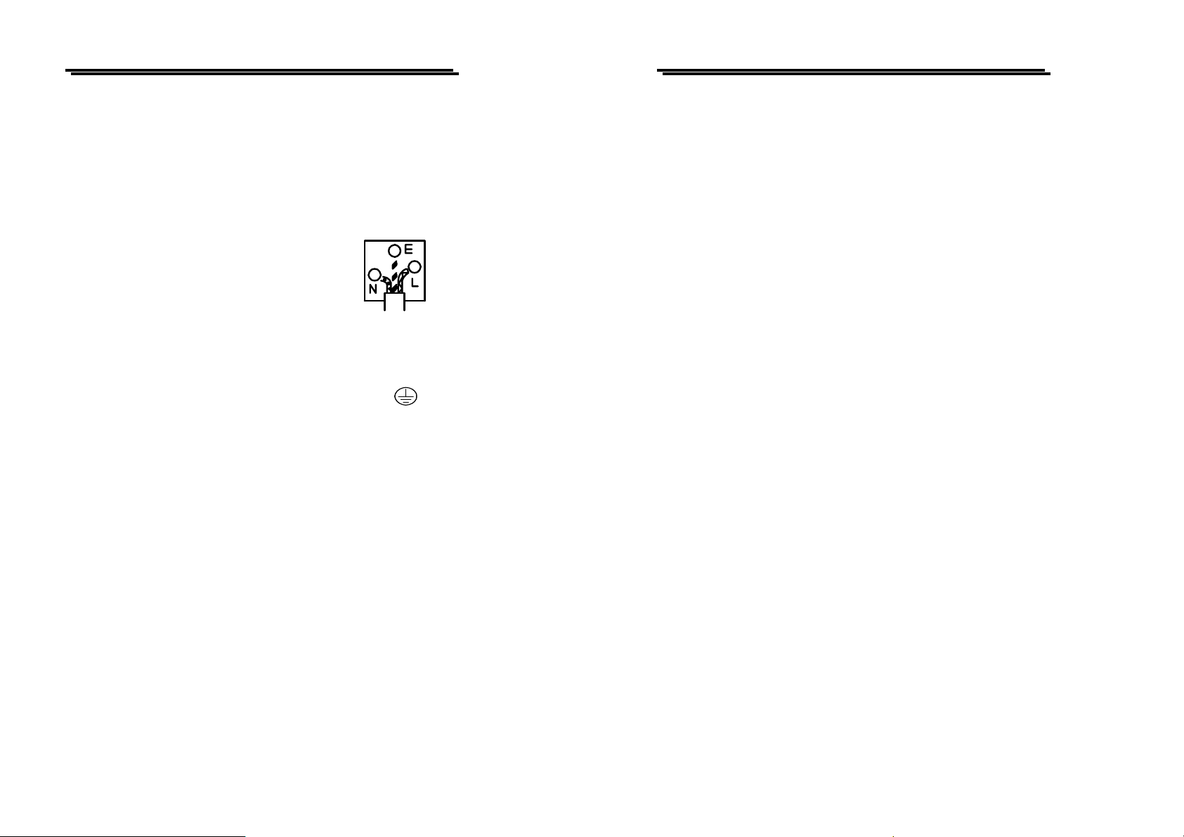
FOR UNITED KINGDOM ONLY
NOTE: This lead/appliance must only be wired by competent persons
WARNING: THIS APPLIANCE MUST BE EARTHED
IMPORTANT: The wires in this lead are coloured in accordance with
the following code:
Green/ Yellow: Earth
Blue: Neutral
Brown: Live(Phase)
As the colours of the wires in main leads may not correspond with the colours
marking identified in your plug/appliance, proceed as follows:
The wire which is coloured Green & Yellow must be connected to the Earth
terminal marked with the letter E or by the earth symbol
or Green & Yellow.
The wire which is coloured Blue must be connected to the terminal which is marke
with the letter N or coloured Blue or Black.
The wire which is coloured Brown must be connected to the terminal marked with
the letter L or P or coloured Brown or Red.
If in doubt, consult the instructions provided with the equipment or contact the
supplier.
This cable/appliance should be protected by a suitably rated and approved HBC
mains fuse : refer to the rating information on the equipment and/or user
instructions for details. As a guide, cable of 0.75mm² should be protected by a 3A
or 5A fuse. Larger conductors would normally require 13A types, depending on the
connection method used.
Any moulded mains connector that requires removal / replacement must be
destroyed by removal of any fuse & fuse carrier and disposed of immediately, as a
plug with bared wires is hazardous if a engaged in live socket. Any re-wiring must
be carried out in accordance with the information detailed on this label.
or coloured Green
USER MANUAL
1. INTRODUCTION
The regulated DC power supply series is designed to be used in applications such as
powering operational amplifier, push-pull stages, logic circuit and definition systems where
plus and minus voltages are required to track with an insignificant error. To represent an
operation convenience, GPS-4302, GPS-4303 and GPS-4251 have four independent power
supplies (while GPS-2303 has two and GPS-3303 has three) housed in a single package.
GPS-4302, GPS-4303 and GPS-4251
adjustable DC power supplies (while two for GPS-2303 and three for GPS-3303). A front
panel switch selects one of three operation modes of independent, series and parallel. In the
independent mode, the output voltage and current of each supply are controlled separately,
and each supply is isolated up to 300V from output to chassis or output to output. In the
tracking mode, both outputs are automatically connected in series or parallel, and the
controls of the left supply adjust the magnitudes of both the positive and negative output
voltages. Because the outputs are connected in a tracking configuration, any internal
disturbance in the master supply (such as drift or ripple) will cause an equal percentage
change in the outputs of both the supplies.
Each power supply (except CH3 for GPS-3303 and CH4 for GPS-4302&4303&
is a completely transistorized, well-regulated, constant voltage/constant current supply that
will provide full rated output voltage at the maximum output current or can be continuously
adjusted throughout the output range. The front panel current controls can be used to
establish the output current limit (overload or short circuit) when the supply is used as a
constant voltage source (independent or tracking modes) and the voltage controls can be
used to establish the voltage limit (ceiling) when the supply is used as a constant current
source (independent mode only). The supply will automatically cross over from constant
voltage to constant current operation (current limited operation in the tracking mode). Each
power supply (CH1~CH4) has its own front panel meter that can measure output voltage or
current. One power supply may be used as a CH1 supply controlling, one CH2 supplies
furnishing various voltage or current for a system. When operate with the front panel mode
switch in the tracking position, the instrument is automatically internally connected in
auto-tracking configuration.
For audio production line, the continuous or dynamic load can be internally selected.
When the connector (J111&J309) is connected to “ON” position the unit is suitable for
audio power Amplifier application (Normal setting to “OFF” position).
consist of four identical, independent,
4251)
v
1
MULTI-OUTPUT POWER SUPPLY
MULTI-OUTPUT POWER SUPPLY
USER MANUAL
2. SPECIFICATIONS
2-1. General
Main Supply (switch selectable) : 100V/120V/220V ± 10%(230V +10%~-6%) 50/60Hz.
Operation Environment
Storage Temperature & Humidity : -10℃ to 70℃.70% (maximum).
Accessories : Operation Manual ×1.
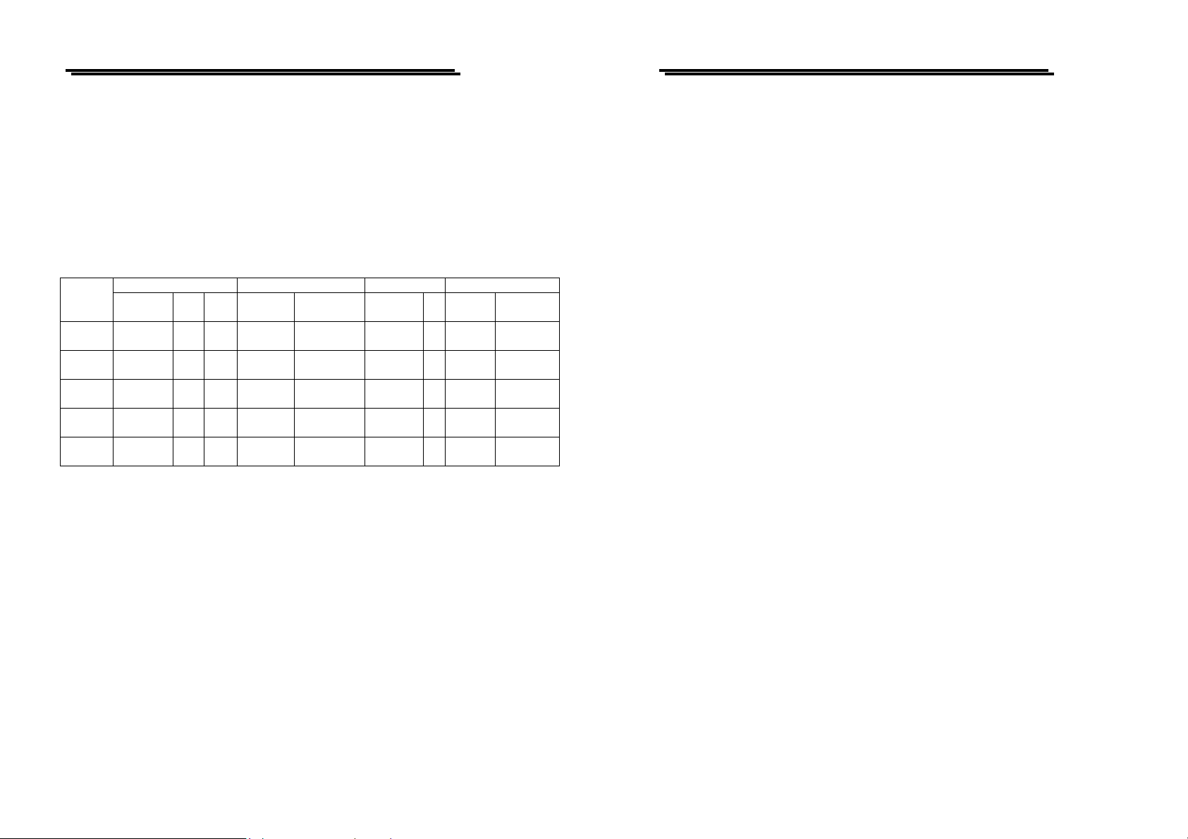
Table 2-1:
MODEL
GPS-2303
GPS-3303
GPS-4303
GPS-4302
GPS-4251
Dimensions : 255(W) ×145(H) ×265(D) m/m
Weight (kg) : 7.0 kg.
2-2. Operation Mode
(1) Independent : Two independent outputs and
(2) Series : Output from 0 to rating volts at rating amperes each.
(3) Parallel : Output from 0 to double rating amperes at rating
2-3. Constant Voltage Operation
(1) Output voltage range : 0 to rating voltage continuously adjustable.
(2) Regulation : Line regulation≦0.01% + 3mV.
REPLACED FUSE TYPE RATES INPUT TEST LEAD
Independent Series Para 100V/120V 220V/230V WATTS VA
0~30V×2
0~3A×2
0~30V×2
0~3A×2
0~30V×2
0~3A×2
0~30V×2
0~2A×2
0~25V×2
0~0.5A×2
60V 3A30V 6AT6A
60V 3A30V 6AT6.3A
60V 3A30V 6AT6.3A
60V 2A30V 4AT5A
50V
25V 1AT2.5A
0.5A
:Indoor use.
Altitude up to 2000m.
Ambient temperature 0℃ to 40℃.
Relative humidity 80% (maximum).
Installation category II.
Pollution degree 2.
Current
≦3A
Current<10A
250V
250V
250V
250V
250V
T3A
250V
T3.15A 250V 420 550 1 2
T3.15A 250V 420 550 2 2
T3A
250V
T1.25A
250V
350 450 0 2
320 420 2 2
150 185 4 0
CH3: 2.2~5.2V output for GPS-4302/4303, 3~6V
output for GPS-4251, Fixed 5V for GPS-3303.
CH4: 8~15V output for GPS-4302/4303/4251.
Output from 0 to rating volts and 0 to rating amperes.
: Output from 0 to double rating volts at rating amperes.
volts.
: Load regulation≦0.01%+3mV(rating current≦3A).
: Load regulation≦0.02%+5mV ( rating current>3A).
4A≦
USER MANUAL
(3) Recovery time :≦100μs (50% load change, minimum load 0.5A ).
(4) Ripple & Noise :≦1mVrms (5Hz-1MHz ).
(5) Temperature coefficient :≦300ppm/℃.
2-4. Constant Current Operation
(1) Output current range : 0 to rating current continuously adjustable.
(2) Regulation : Line regulation≦0.2% + 3mA.
: Load regulation≦0.2% +3mA.
(3) Ripple current :≦3mArms.
2-5. Tracing Operation
(1) Parallel Operation
Regulation : Line regulation≦0.01% + 3mV.
: Load regulation≦0.01%+3mV (rating current≦3A).
≦0.02%+5mV (rating current >3A).
(2) Series Operation
Regulation : Line regulation≦0.01%+5mV.
: Load regulation≦300mV.
A. Positive and Negative supply (Fig 5-4) CH2 tracking error ≦0.5%+10mV of the CH1
(No load, with load add load regulation≦300mV)
B. Single supply (Fig. 5-3)
2-6. Meter
A. Display A : 3 digits panel meter×2 (0.5” Red LED display).
Display V : 3 digits panel meter × 2 (0.5” Green LED display).
B. Accuracy :OUT ON±(0.5% of rdg + 2 digits)
:OUT OFF ± (0.5% of rdg+8 digits)(invalid for
GPS-2303)
C. Voltmeter : 99.9V of full scale.
D. Ammeter : 9.99A of full scale.
2-7. CH3 Output Specifications
(1) Regulation : Line regulation≦5mV, load regulation≦15mV.
(2) Ripple & Noise : ≦2mVrms.
(3) Outout Voltage range : GPS-4302/4303: 2.2~5.2V±8% continuous adjustment,
GPS-3303 fixed 5V±8% continuous adjustment,
GPS-4251 3~6V±8% continuous adjustment
(4) Output current : 3A for GPS-3303&4302, 1A for GPS-4303, 2.5A for
GPS-4251.
2-8. CH4 Output Specifications
(1) Regulation : Line regulation≦5mV, load regulation≦10mV.
(2) Ripple & Noise :≦2mVrms.
(3) Outout Voltage range : GPS-4302/4303/4251: 8~15V±8% continuous
adjustment.
(4) Output current : 1A
2
3
MULTI-OUTPUT POWER SUPPLY
MULTI-OUTPUT POWER SUPPLY
USER MANUAL
2-9. Insulation
Between chassis and output terminal : 20MΩ or above (DC 500V).
Between chassis and AC cord : 30MΩ or above (DC 500V).
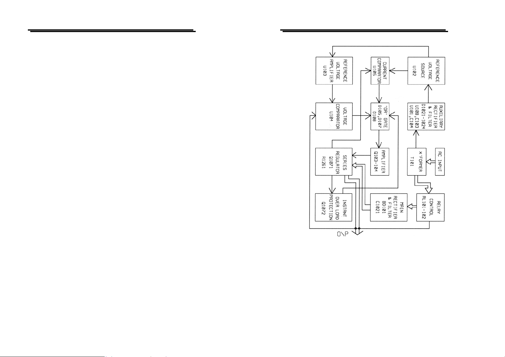
3. THEORY OF OPERATION
The power supply consists of an AC input circuit and transformer; a bias
supply consisting of an rectifier, filter, pre-regulator and reference voltage source;
a main regulator circuit consisting of the main rectifier and filter, a series regulator,
a current comparator, a voltage comparator, a reference voltage amplifier and a
relay control circuit. The circuit element consists of integrated circuit U101, U102,
U103, U104, U105, U108.
The circuit arrangement is shown as block diagram in Fig. 3-1. The circuitry is
discussed with reference to the block diagram function description. Single phase
input power is applied to transformer through the input circuit.
Auxiliary rectifier D1021~1024 provides a bias voltage, filtered by capacitor
C103, C104 for the preregulator. U101, U108 that provides a regulator voltage for
elements of action.
The main rectifier, a full wave bridge rectifier provides the power which is
filtered by capacitor, C1021 and then regulated via a series regulator and delivers
to the output.
U105 acts as a current limiter. When current is over predetermined rating it is
activated and decreases the current.
U102 provides a reference voltage for U103, U105.U103 is a inverter
amplifier.U104 is a comparator amplifier which compares reference voltage and
feedback voltage, and then delivers to Q103, Q104, which then calibrates the
output voltage.
Q113 is activated when the unit is overload. It controls Q103 current
magnitude which limits the output current.
The relay control circuit provides limited power dissipation in series regulator.
USER MANUAL
Figure 3-1 Block Diagram
4
5
 Loading...