

Page 1

Current Probe and Power Supply
USER MANUAL
GW INSTEK PART NO. 82CP-425P0M01
ISO-9001 CERTIFIED MANUFACTURER
Page 2

November 2010 edition
This manual contains proprietary information, which is protected by
copyright. All rights are reserved. No part of this manual may be
photocopied, reproduced or translated to another language without
prior written consent of Good Will Corporation.
The information in this manual was correct at the time of printing.
However, Good Will continues to improve its products and therefore
reserves the right to change the specifications, equipment, and
maintenance procedures at any time without notice.
Good Will Instrument Co., Ltd.
No. 7-1, Jhongsing Rd., Tucheng City, Taipei County 236, Taiwan.
Page 3

TABLE OF CONTENTS
Table of Contents
SAFETY INSTRUCTIONS .................................. 5
Safety Symbols ....................................................................... 5
PRECAUTIONS ................................................. 7
Preliminary Check ............................................................... 7
OVERVIEW ..................................................... 13
Current Proble Overview ................................................... 13
Features ............................................................................ 13
Names of Parts(Current Probe) ......................................... 14
External view ......................................................................... 14
Parts of the Sensor ............................................................ 15
Names of Parts(Power supply) .......................................... 17
MEASURE PROCEDURE .................................................... 20
Preparations for Measurement (Current Probe)................. 20
Demagnetizing and Zero Adjustment ................................... 22
Measurement Procedure (Current Probe) .......................... 24
Preparations (Power supply) ............................................. 30
Measurement Procedure (Power supply) ........................... 31
APPENDIX ...................................................... 32
Fuse Replacement (for GCP-206P only) ............................. 32
Change the power supply voltage setting .......................... 34
Current Probe Specifications ............................................. 35
Model-specific specifications ............................................... 35
Common specifications (for GCP-530 and GCP-1030) ....... 36
Power Supply Specifications .............................................. 39
Model-specific specifications ............................................... 39
Common specifications (for GCP-206P and GCP-425P)..... 40
3
Page 4

TABLE OF CONTENTS
4
Page 5

SAFETY INSTRUCTIONS
SAFETY INSTRUCTIONS
Safety Symbols
This manual contains information and warnings essential for safe
operation of the device and for maintaining it in safe operating
condition. Before using the device, be sure to carefully read the
following safety notes.
symbol printed on the device indicates that
The
the user should refer to a corresponding topic in the
manual (marked with the
the relevant function.
symbol) before using
In the manual, the
important information that the user should read
before using the device.
Indicates that application around or removal from
live lines is only permitted on condition that the
lines are insulated.
Indicates a grounding terminal
Indicates AC (Alternating Current)
Indicates the ON side of the power switch.
Indicates the OFF side of the power switch.
Indicates a fuse.
symbol indicates particularly
5
Page 6

GCP Series User Manual
The following symbols in this manual indicate the relative
importance of cautions and warnings.
DANGER
WARNING
CAUTION
NOTE
Indicates that incorrect operation presents an
extreme hazard that could result in serious injury or
death to the user.
Indicates that incorrect operation presents a
significant hazard that could result in serious injury
or death to the user.
Indicates that incorrect operation presents a
possibility of injury to the user or damage to the
device.
Indicates advisory items related to performance or
correct operation of the device.
(Measurement categories) EN 61010-1:2001 specifies the
measurement categories and their requirements as follows. The
device falls under category I.
• Measurement category IV is for measurement performed at the
source of a low-voltage installation.
• Measurement category III is for measurement performed in a
building installation.
• Measurement category II is for measurement performed on
circuits directly connected to a low voltage installation.
• Measurement category I is for measurements performed on
circuits not directly connected to Mains.
6
Page 7

PRECAUTIONS
PRECAUTIONS
Follow these precautions to ensure safe operation
and to obtain the full benefits of the various
functions.
Preliminary Check
Before using the device the first time, verify that it operates normally
to ensure that the no damage occurred during storage or shipping. If
you find any damage, contact your dealer.
• To avoid short circuits and potentially life-
DANGER
threatening hazards, never attach the GCP-530 or
GCP-1030 to a circuit that operates at more than
300V, or over bare conductors.
• When conductors being measured carry in excess
of the safe voltage level (SELV-E) and not more
than 300 V, to prevent short circuits and electric
shock while the core section is open, make sure
that conductors to be measured are insulated with
material conforming to
(1) Measurement CategoryⅠ,
(2) Basic Insulation Requirements for Working
Voltages of 300 V, and
(3) Pollution Degree 2.
For safeties sake, never use this sensor on bare
conductors. The core and shield case are not
insulated.
7
Page 8

GCP Series User Manual
Un-insulated
(core and
shield case)
• Be careful to avoid damaging the insulation
surface while taking measurements.
• This instrument is made for use with the GCP-
206P or GCP-425P POWER SUPPLY. It is possible
to use a power supply other than the GCP-206P or
GCP-425P, provided that the connector and pin
assignments match, and that voltage and other
electrical specifications are satisfied. In the interest
of safety, make sure that the power supply has a
protective earthing with double- insulation
construction.
• Make sure that the waveform measuring
equipment connected to this device's output
terminal (BNC) is equipped with a protective
earthing with double-insulation construction.
• If the waveform measuring instrument being
connected to the output terminal (BNC) on this
device is equipped with any other measurement
terminals, take the following precautions to ensure
that the other instrument does not form a bridge
between the probe and any hazardous live of a
part.
1. Isolate the terminal to which the probe is
connected from other terminals on the measuring
instrument using basic insulation conforming to
the measurement category, working voltage, and
pollution degree requirements of the circuit being
tested.
8
Page 9

PRECAUTIONS
2. If basic insulation requirements cannot be met
between the terminal to which this device is
connected and other terminals of the measuring
instrument, make sure that the voltage input to
the measurement terminal does not exceed the
safe voltage level (SELV- E).
3. Read and observe all warnings and precautions
relating to electrical safety for the measuring
instrument being connected to the probe.
Refer to the following standards regarding the
meanings of underlined terms.
IEC61010-1
IEC61010-031
IEC61010-2-032
• Be sure to observe all operating precautions for the
waveform monitoring instrument (oscilloscope or
recorder) and other measurement instruments to
which this device is connected.
• When using a measurement instrument that does
not provide isolation between its input terminals
and chassis or other input terminals, please pay
attention to the following points. If a signal is
applied to an input terminal other than that to
which this device is connected, do not connect the
ground-side terminal to any non-ground potential.
Otherwise, short-circuit current will flow through
the GCP-206P or GCP-425P or this device from the
ground terminal, which could cause an electrical
accident or damage.
9
Page 10

GCP Series User Manual
WARNING
CAUTION
• Do not allow the device to get wet, and do not take
measurements with wet hands. This may cause an
electric shock.
• To avoid electric shock when measuring live lines,
wear appropriate protective gear, such as insulated
rubber gloves, boots and a safety helmet.
• To avoid damage to the device, protect it from
physical shock when transporting and handling.
Be especially careful to avoid physical shock from
dropping.
• This device should be installed and operated
indoors only, between 0 and 40°C (32 to 104°F) and
80% RH or less.
• Do not store or use the device where it could be
exposed to direct sunlight, high temperature or
humidity, or condensation. Under such conditions,
the device may be damaged and insulation may
deteriorate so that it no longer meets
specifications.
• This device is not designed to be entirely
waterproof or dustproof. To avoid damage, do not
use it in a wet or dusty environment.
10
Page 11

PRECAUTIONS
• The sensor head is a precision assembly including
a molded component, a ferrite core, and a Hall
effect element. It may be damaged if subjected to
sudden changes in ambient temperature, or
mechanical strain or shock, and therefore great
care should be exercised in handling it.
• The matching surfaces of the sensor head are
precisely ground, and should be treated with care.
If these surfaces are scratched, performance may
be impaired.
• To avoid damaging the sensor cables, do not bend
or pull the sensor cable and power supply cable.
• To clean the device, wipe it gently with a soft cloth
moistened with water or mild detergent. Never
use solvents such as benzene, alcohol, acetone,
ether, ketones, thinners or gasoline, as they can
deform and discolor the case.
• When the power is on, keep the core section of the
sensor closed, except when clamping them onto
the conductor to be measured. The facing surface
of the core section can be scratched while it is
open.
• Keep the clamp jaws and core slits free from
foreign objects, which could interfere with
clamping action.
• Keep the sensor head closed when not in use, to
avoid accumulating dust or dirt on the mating core
surfaces, which could interfere with clamp
performance.
• Avoid stepping on or pinching the cable, which
could damage the cable insulation.
• Keep the cables well away from heat sources, as
bare conductors could be exposed if the insulation
melts.
11
Page 12

GCP Series User Manual
NOTE
• Correct measurement may be impossible in the
presence of strong magnetic fields, such as near
transformers and high-current conductors, or in
the presence of strong electromagnetic fields such
as near radio transmitters.
• When sending the device for repair, carefully to
prevent damage in transit. Include cushioning
material so the instrument cannot move within the
package. Be sure to include details of the problem.
12
Page 13

OVERVIEW
OVERVIEW
Current Proble Overview
This device can be directly connected to a BNC input connector of a
waveform measuring instrument such as an oscilloscope or recorder,
and by clamping on a conductor to be measured, allows the current
waveform to be easily captured.
Features
•
Highly accurate current detection
• Easy current measurement
• Broadband frequency characteristics DC to 50 MHz(for GCP-530)
• Broadband frequency characteristics DC to 100 MHz(for GCP-1030)
• Compact and permits measurement of low current levels
• Easy protect function at excessive input
13
Page 14

GCP Series User Manual
Names of Parts(Current Probe)
External view
14
Page 15

OVERVIEW
Parts of the Sensor
Opening lever
X
Operating lever for opening the sensor head.
Always use this lever to open the sensor head.
Sensor head
Y
Demagnetizing
Z
switch
(DEMAG)
Zero
[
adjustment
dial (ZERO
ADJ)
Coarse
\
adjustment
trimmer
This clamps the conductor being measured, and
carries out the actual current measurement. It is a
precision assembly including a molded
component, a ferrite core, and a Hall effect
element. It may be damaged if subjected to
sudden changes in ambient temperature, or
mechanical strain or shock, and therefore great
care should be exercised in handling it.
This demagnetizes the core if it has been
magnetized by switching the power on and off, or
by an excessive input. Always carry out
demagnetizing before measurement. The
demagnetizing process takes about one second.
During demagnetizing, a demagnetizing
waveform is output.
Use the zero adjustment dial to correct for the
effect of a voltage offset or temperature drift on
the device. When beginning measurement, after
demagnetizing always carry out zero adjustment.
Use this only when adjustment is not possible
within the range of the zero adjustment dial.Use a
nonconductive screwdriver (e.g. ceramic driver)
for adjustment.
Output
]
connector
Power plug
^
The current waveform of the measured conductor
is output at a constant rate (0.1 V/A).
Connect to the BNC input connector of the
waveform measuring instrument.
Connect this to the GCP-206P or GCP-425P
POWER SUPPLY receptacle to supply power to
the sensor terminator.
15
Page 16

GCP Series User Manual
DANGER
NOTE
To avoid electric shock, do not touch the portion
beyond the protective barrier during use.
• The output of this device is terminated
internally. Use a high-impedance input to the
measuring instrument. With an input
impedance of 50Ω, accurate measurement is not
possible.
• If using BNC-banana plug adapters or similar to
connect to input terminals other than BNC
connectors, make sure the polarity is correct.
• Turn the collar until it clicks, and check that it is
locked securely.
16
Page 17
OVERVIEW
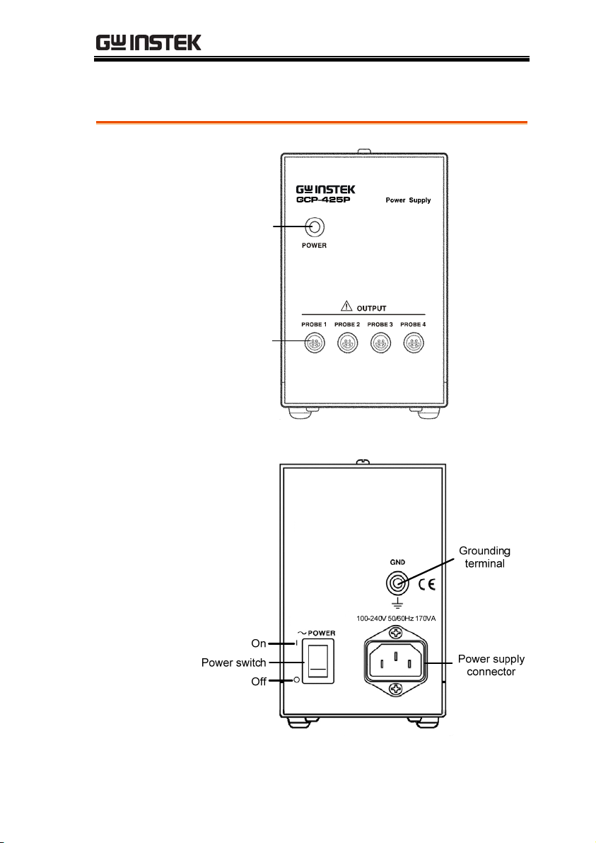
Names of Parts(Power supply)
Front view
Rear View
Power
Power
indicator
indicator
Power
Power
supply
supply
receptacles
receptacles
GCP-425P
GCP-425P
17
Page 18
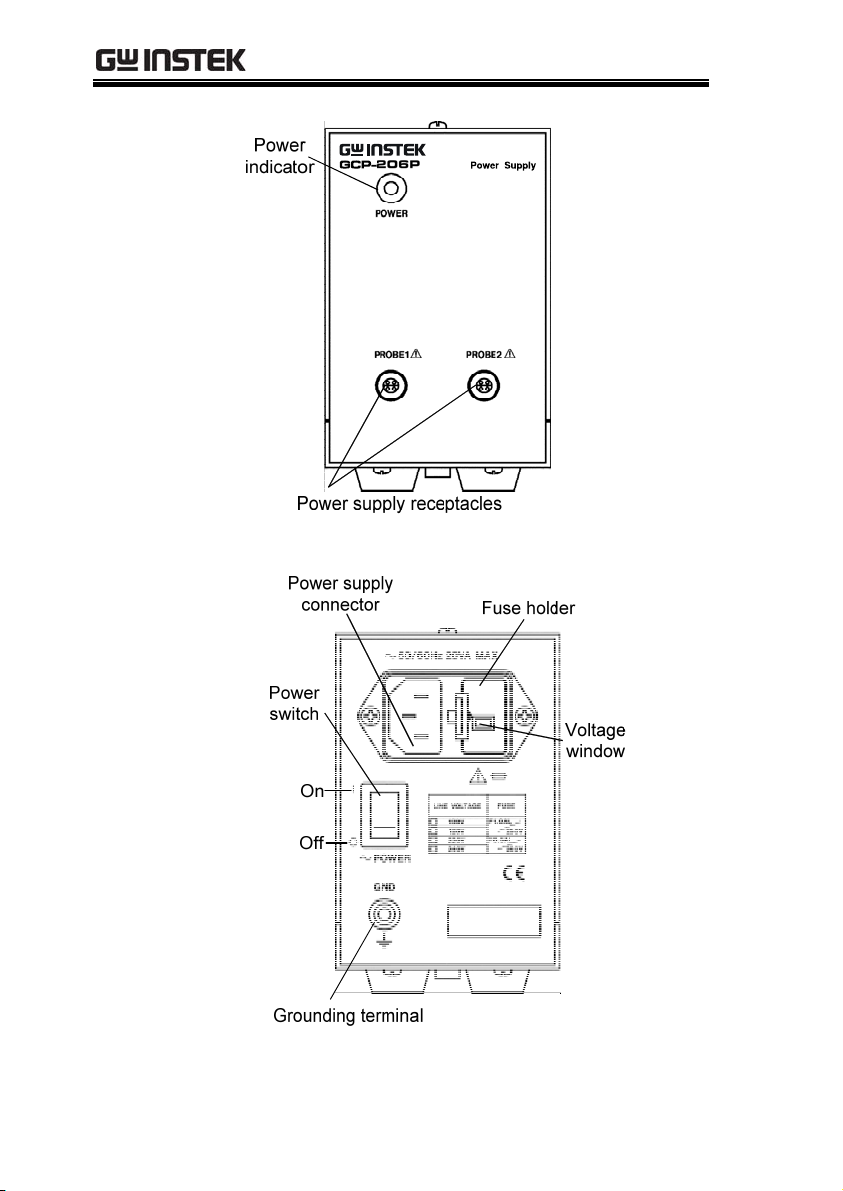
Front view
GCP Series User Manual
GCP-206P
Rear View
18
GCP-206P
Page 19

OVERVIEW
Power Supply
Receptacle
19
Page 20

GCP Series User Manual
MEASURE PROCEDURE
Preparations for Measurement (Current
Probe)
Procedure
CAUTION
NOTE
1. Have the GCP-206P or GCP-425P POWER
SUPPLY, and oscilloscope or recorder for
waveform measurement ready.
Before turning on the power, make sure that the
voltage of the power supply being used matches the
supply voltage indicated on the rear panel of the
GCP-206P or GCP-425P
The output of this device is terminated internally.
Use a high-impedance input to the measuring
instrument. With an input impedance of 50Ω,
accurate measurement is not possible.
2. Turn the power switch off and connect the
power cord.
3. Connect the power plug of the GCP-530 or GCP1030 to the power receptacle of the GCP-206P or
GCP-425P.
20
Page 21

OVERVIEW
4. Turn the GCP-206P or GCP-425P power switch
21
Page 22

GCP Series User Manual
Demagnetizing and Zero Adjustment
Procedure
CAUTION
1. With the waveform measurement instrument
input at ground, adjust the trace to the zero
position.
2. Set the input coupling of the waveform
measurement instrument to DC.
3. Connect the output connector of the GCP-530 or
GCP-1030 to the input connector of the
waveform measurement instrument. Turn the
collar until it clicks, and check that it is locked
securely.
• When disconnecting the output connector, be
sure to release the lock before pulling off the
connector. Forcibly pulling the connector
without releasing the lock, or pulling on the
cable, can damage the terminator.
• If using BNC-banana plug adapters or similar to
connect to input terminals other than BNC
connectors, make sure the polarity is correct.
22
Page 23

OVERVIEW
• Do not demagnetize while the GCP-530 or GCP-
1030 is clamping a conductor to be measured.
Demagnetizing causes current to flow into the
conductor, which may damage parts in the
circuit to be measured.
• Check that the conductor being measured is not
clamped when supplying power to the GCP-530
or GCP-1030 for the same reason. Demagnetized
waveforms are generated when supplying
electric power.
4. Without clamping the conductor to be
measured, press the opening lever until the
"UNLOCK" indication disappears, and check
that the sensor head is properly closed.
5. Press the demagnetizing switch (DEMAG) on
the terminator.
6. Turn the zero adjustment dial on the terminator,
to adjust the trace to the zero position.
7. If zero adjustment is not possible in step 6, turn
the coarse adjustment trimmer to bring the trace
within the range of adjustment by the zero
adjustment dial.
23
Page 24

GCP Series User Manual
Measurement Procedure (Current Probe)
Procedure
1. Check that the system is safe, and that the
preparations described in the preceding section
have been carried out.
2. Pull the sensor opening lever, so that the sensor
head opens.
3. Align the sensor so that the current direction
indication corresponds to the direction of
current flow through the conductor to be
measured, and clamp so that the conductor is in
the center of the sensor aperture.
4. Press the opening lever on the sensor head until
the "UNLOCK" indication disappears, and check
that the opening lever is firmly locked and the
sensor head securely closed.
24
Page 25

OVERVIEW
NOTE
Fig. 1
5. It is now possible to monitor the current
waveform. The output rate of the GCP-530 or
GCP is 0.1 V/A. The current sensitivity can be
derived from the voltage sensitivity of the
waveform measurement instrument. For
example, if the voltage sensitivity is
10mV/division, the current sensitivity is
100mA/division.
• When using the GCP-530 or GCP-1030, note that
two current probes may not be used
simultaneously with the GCP-425P POWER
SUPPLY, depending on the current to be
measured.
• The current consumption of current probes
depends on the current to be measured. Confirm
that the total current consumption of the current
probes do not exceed the rated output current of
the GCP-425P. See Fig. 1.
600
500
400
300
200
100
0
01020304050
AC(f=50Hz)
DC
Current (A)
Current consumption* vs. current to be
measured(typical)
*The sum total of a positive and negative current
consumption
25
Page 26

CAUTION
GCP Series User Manual
• The maximum continuous input range is based
on heat that is internally generated during
measurement. Never input current in excess of
this level. Exceeding the rated level may result in
damage to the probe.
• The maximum continuous input range varies
according to the frequency of the current being
measured. See the figures 3 on page 37 .
• If excess current is input, generated heat activates
a built-in safety function that blocks normal
output. If this happens, remove the input
immediately (remove the sensor from the
conductor being measured, or reduce the input
current to zero). Wait until the sensor has had
sufficient time to cool before resuming operation.
• Even if the input current does not exceed the
rated continuous maximum, continuous input for
an extended period of time may result in
activation of the safety circuit to prevent damage
resulting from heating of the sensor.
• At high ambient temperatures, the built-in safety
circuit may activate at current input levels below
the rated continuous maximum.
• Continuous input of current exceeding the rated
maximum or repeated safety circuit activation
will degrade performance of the safety circuit,
possibly resulting in damage to the device.
• The maximum input range is indicated by the
continuous maximum input range. It is also
indicated by another product specification
Maximum peak current: Noncontinuous 50 A
peak. This means that the upper limit of the
waveform response is 50 A peak. Make sure that
the input does not exceed the continuous
maximum input range in rms.
26
Page 27
OVERVIEW
• Do not place any unclamped conductor with an
electric current of a frequency of 10 kHz or more
near the sensor head. Current flowing in the
conductor nearby may heat up the sensor head
and cause its temperature to rise, leading to
damage to the sensor. For example, when one
side of a go-and-return conductor is clamped and
the other side is also placed near the sensor head
as shown in the diagram, even if the electric
current is lower than the consecutive maximum
current, electric currents in both sides will heat
up the wires and raise the temperature, thereby
causing damage to the sensor.
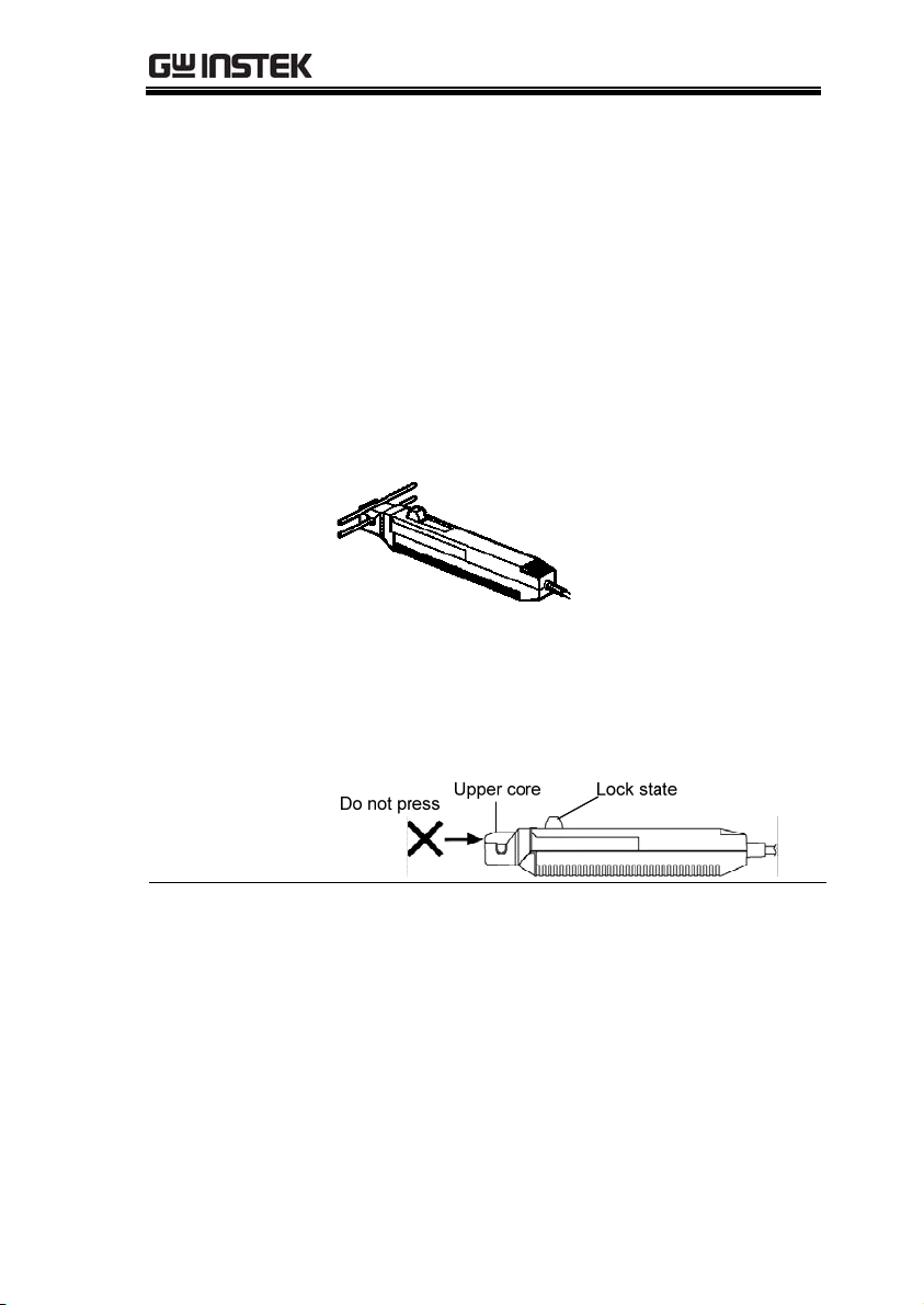
• When opening the sensor head of the probe, be
sure to operate with the opening lever. If an
upper core is forced to open, when the sensor
head is locked, the open-close mechanism can be
damaged.
NOTE
• The output of this device is terminated internally.
Use a waveform measurement instrument with
an input impedance of at least 1 MΩ.
• Immediately after powering on, this device may
be subject to an appreciable offset drift due to the
effect of self-heating. To counteract this, allow the
device to warm up for about 30 minutes before
carrying out measurement.
27
Page 28

GCP Series User Manual
• Depending on the measured current frequency,
however some sound may be produced by
resonance, it has no effect on measurements.
• When performing continuous measurements, it is
necessary to be aware that the offset voltage
drifts, depending on factors such as the ambient
temperature.
• Under certain circumstances, oscillation may
occur if the probe is connected to the GCP-206P
or GCP-425P POWER SUPPLY while the power
supply is on. This does not indicate a
malfunction. Oscillation can be stopped and
operation restored to normal by opening and
closing the sensor head.
• Depending on the measured current frequency,
however some sound may be produced by
resonance,it has no effect on measurement.
• The measurement may be affected by the position
within the clamp aperture of the conductor being
measured. The conductor should be in the center
of the clamp aperture.
• When carrying out measurement, press the
opening lever until the "UNLOCK" indication
disappears, and check that the sensor head is
properly closed. If the sensor head is not properly
closed, accurate measurement will not be
possible.
28
Page 29
OVERVIEW
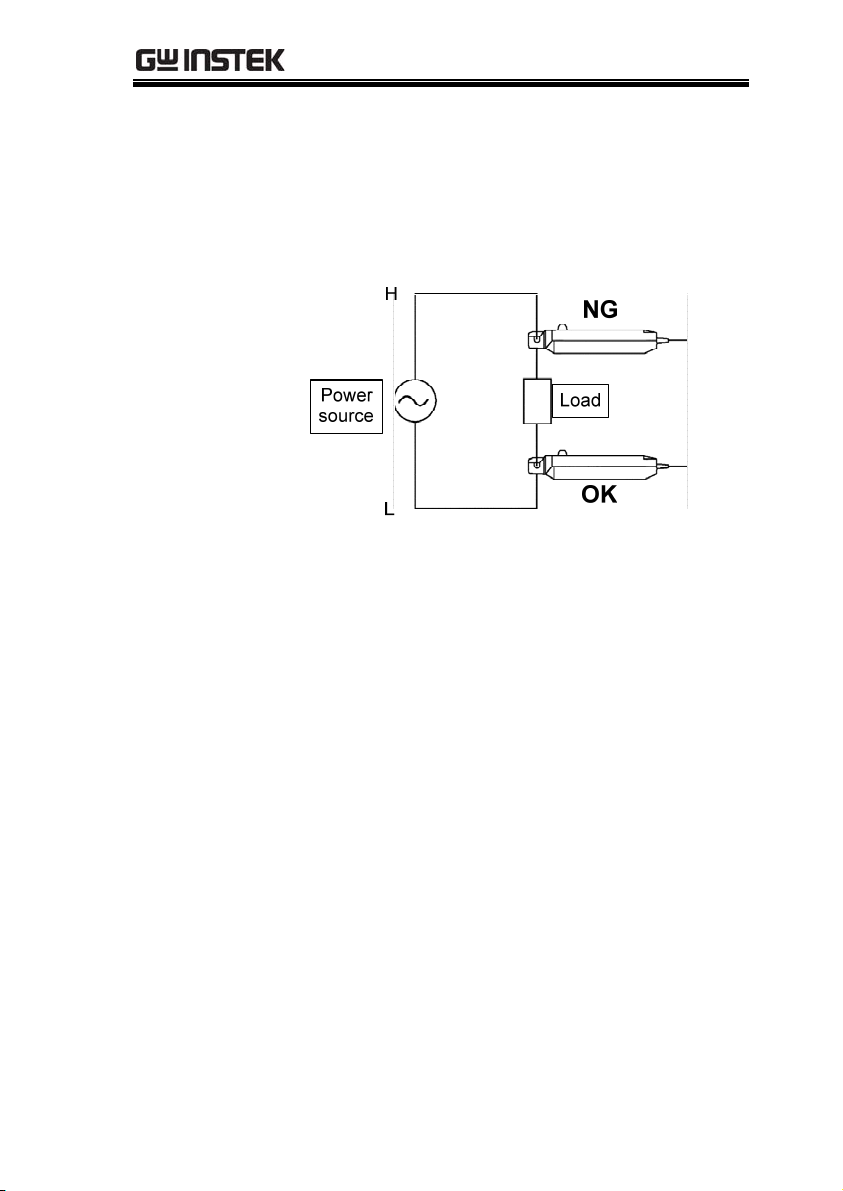
• At high frequencies, common mode noise may
affect measurements taken on the high voltage
side of circuits. If this occurs, reduce the
frequency range of the waveform measuring
instrument, or clamp onto the low voltage side of
the circuit, as appropriate.
• Accurate measurement may be impossible in
locations subject to strong external magnetic
fields, such as transformers and high-current
conductors, or in locations subject to strong
external electric fields, such as radio transmission
equipment.
29
Page 30
GCP Series User Manual
Preparations (Power supply)
Procedure
WARNING
DANGER
1. Turn the power switch off and connect the
power cord. To ensure safety, connect the power
cord to a properly grounded outlet.
2. Connect the power plug of the sensor to be used
to the power receptacle of the GCP-206 or GCP425P.
3. Turn the GCP-206 or GCP-425P power switch
on, and check that the front panel power
indicator lights.
Before turning the device on, make sure the supply
voltage matches that indicated on its power
connector. Connection to an improper supply
voltage may damage the device and present an
electrical hazard.
• To avoid accidents, when using other
measurement devices with this one, observe the
usage precautions described for each device.
• To avoid electric shock or damage, when
connecting the current probe to a measurement
device that does not have its input terminals
isolated from the chassis, or to an device that
does not have it input terminals isolated from
one another and signals are applied to other
terminals, do not connect the grounding terminal
to any point that is not at ground potential.
Otherwise, if the grounding terminal is
connected to a point that is not at ground
potential, a short circuit will occur.
30
Page 31

OVERVIEW
Measurement Procedure (Power supply)
NOTE
• Make sure the sum of the current consumption of
the connected current probe(s) does not exceed the
rated output current of the GCP-425P (See Fig.1)
on page 25.
• When using the GCP-425P with Model GCP-530 or
GCP-1030 Current Probe, in general only one
current probe may be connected. However,
depending on the current level of the object under
test, two current probes may be connected
simultaneously.
• The current consumption of a current probe is
dependent upon the current level of the object
under test.
31
Page 32

GCP Series User Manual
APPENDIX
The power supply fuse for the GCP-425P, and the
power supply voltage selector, are housed in the
power input socket on the rear panel.
Fuse Replacement (for GCP-206P only)
Procedure
1. Turn the power switch off, and then disconnect
the power cord.
2. Using a flat screwdriver, pry the catch which
holds the fuse holder into the power input
socket as shown in the figure, and then remove
the fuse holder.
32
Page 33

APPENDIX
3. Remove the fuse on the fuse holder and replace
with a new one of the same rating and
specification.
4. Insert the fuse holder back into the power input
socket to finish the replacement of fuse.
33
Page 34

GCP Series User Manual
Change the power supply voltage setting
Procedure
1. Repeat steps 1-2 in the “Fuse replacement”
section on page 32.
2. Remove the voltage selector from the fuse
holder, rotate it to the desired supply voltage
value and then insert back into the fuse holder.
The voltage vaule will appear in the voltage
window. Check the setting value again.
3. Insert the fuse holder back into the power input
socket to finish setting the supply voltage
setting.
34
Page 35

APPENDIX
Current Probe Specifications
Accuracy is guaranteed at 23°C~+5°C (72°F±9°F) after the power has
been on for 30 minutes.
Model-specific specifications
GCP-530 GCP-1030
Frequency range DC to 50 MHz (-3 dB)
(Characteristics shown in Fig.
2A)
Rise time 7 ns or less 3.5 ns or less
Maximum rated
power
Weight Approx. 230g(8.1oz) Approx. 240g(8.5oz)
Accessories Instruction manual, Soft case Instruction manual, Carrying
Fig. 2A
Frequency
characteristics
(Typical
characteristics)
5.6 VA 5.3 VA
DC to 100 MHz (-3 dB)
(Characteristics shown in Fig.
2B)
case
Amplitude [dB, 0dB=1V]
Fig. 2B
Frequency
characteristics
(Typical
characteristics)
35
Page 36

GCP Series User Manual
Common specifications (for GCP-530 and GCP-1030)
GCP-530 GCP-1030
Operating
temperature and
humidity range
Rated Supply
voltage
Maximum Peak
Current Input
Maximum
Continuous Input
Range
Output Voltage
Rate
Amplitude Accuracy +1.0% rdg. ±1 mV ; up to 30 Arms
Noise Equivalent to 2.5 mArms or less (for 20 MHz band
Input Impedance (Characteristics shown in Fig.4A and 4B)
Te mp e ra t ur e
Coefficient for
Sensitivity
Storage
Temperature and
Humidity Range
Location for Use Indoor, altitude up to 2000 m (6562 feet)
Effect of External
Magnetic Fields
Maximum Rated
Vol tag e
Diameter of
Measurable
Conductors
Guaranteed
Accuracy Period
Cable Lengths Sensor cable Approx. 1.5 m (59.0"),
0 to 40°C (32 to 104°F), 80 % RH or less (no
condensation)
12 V 0.5 V
Non-continuous 50 Apeak
30 Arms (Derating according to frequency shown in Fig. 3A
and 3B)
0.1 V/A
+2.0% rdg. ; over 30 Arms to 50 Apeak (DC, and 45 to 66
Hz, input within continuous maximum input range)
measuring instrument)
±2% or less (During input of 50 Hz 30 Arms within range of
0 to 40°C (32 to104°F)
-10 to 50°C (14 to 122°F), 80 % RH or less (no
condensation)
Equivalent to a maximum of 20 mA (DC and 60 Hz,
Magnetic field of 400 A/m)
300 V, CAT Ⅰ(insulated conductor)
5 mm dia. 0.2" dia.
1 year (Opening/closing up to 10,000 times)
Power supply cable Approx. 1 m (39.4")
36
Page 37

APPENDIX
External
dimensions
Fig.3 Derating
according to
frequency (For GCP
-530)
Fig.3 Derating
according to
frequency (For GCP
-1030)
Sensor:
Approx. 175(W)×18(H)×40(D)mm
Approx. 6.89"(W)×0.71"(H)×1.58"(D)(excluding
protrusions)
Terminator:
Approx. 55(W)×27(H) ×18(D) mm
Approx. 2.17"(H) ×1.06"(W)×0.71"(D)
30
20
10
0
10 100 1k 10k 100k 1M 10M 100M
Frequency [Hz]
37
Page 38

GCP Series User Manual
M
Fig.4 Input
impedance (For
GCP-530)
Fig.4 Input
impedance (For GC
P-1030)
10
1
100m
10m
Input inpedance[Ω]
1m
100 1k 10k 100k 1M 10M 100
Frequency [Hz]
38
Page 39

APPENDIX
Power Supply Specifications
Model-specific specifications
Cable Lengths Sensor cable Approx. 1.5 m (59.0"),
GCP-425P GCP-206P
Number of power
supply connectors
Rated output
current
Ripple voltage 50 mVp-p or less 3 mVp-p or less (at rated
Load influence Within output voltage limits
Maximum rated
power
Dimensions Approx.
Weight Approx.1.2 kg (42.3 oz.) Approx. 1.1 kg( 38.8 oz)
Accessories Instruction Manual, Power
Rated supply
voltage
Power supply
voltage influence
Power supply cable Approx. 1 m (39.4")
4 2
±2.5 A (sum total of all
channels)
indicated above for current
output in the range 0 to ±2.5
A
170 VA 20 VA
80W × 119H × 200D mm
3.15"W × 4.69"H × 7.87"D
cord
100 to 240V AC (50/60Hz)
(Voltage fluctuations of ±10%
from the rated supply voltage
are taken into account.)
Within output voltage limits
indicated above for the rated
power supply voltage,
10%
600 mA (sum total of all
channels and all output
output current)
Within output voltage limits
indicated above for current
output in the range 0 to 600
73W x 110H x 186D mm
2.87"W x 4.33"H x 7.32"D
Power cord, Instruction
manual, Spare fuse
F1.0 AL/250 V, 20 mm x 5
mm dia. (for 100 V and 120 V
models) or F0.5 AL/250 V, 20
mm x 5 mm dia. (for 220 V
and 240 V models
100 V AC (120, 220, and 240
V require specification)
(Voltage fluctuation of 10%
from the rated supply voltage
are taken into account.)
voltages)
mA
Approx.
39
Page 40

GCP Series User Manual
Rated supply
frequency
50/60 Hz
Common specifications (for GCP-206P and GCP-425P)
Compatible
sensors
Output voltage
Te mp e ra t ur e
influence
Operating temperature and humidity
range
Storage
temperature and
humidity range
Location for use
Standards applying Indoor, altitude up to 2000 m (6562 feet)
GCP-530, GCP-1030 Current Probe
12 V 0.5 V
Within output voltage limits indicated above for ambient
temperature in the range 0 to 40°C (32 to 104°F)
0 to 40°C(32 to 104°F), 80%RH or less (no condensation)
-10 to 50°C(14 to 122°F), 80%RH or less (no condensation)
40
 Loading...