

Page 1

Differential Probe
GDP-025/050/100 Series
USER MANUAL
GW INSTEK PART NO. 82DP-10000MA1
ISO- 9001 CERTIFIED MANUFACTURER
Page 2

This manual contains proprietary information, which is protected by
copyright. All rights are reserved. No part of this manual may be
photocopied, reproduced or translated to another language without
prior written consent of Good Will Corporation.
The information in this manual was correct at the time of printing.
However, Good Will continues to improve its products and therefore
reserves the right to change the specifications, equipment, and
maintenance procedures at any time without notice.
Good Will Instrument Co., Ltd.
No. 7-1, Jhongsing Rd., Tucheng Dist., New Taipei City 236, Taiwan.
Page 3

TABLE OF CONTENTS
Table of Contents
SAFETY INSTRUCTIONS ..........................4
Safety Symbols ........................................................................ 4
Safety Guidelines..................................................................... 5
Power cord for the United Kingdom ...................................... 8
GETTING STARTED ................................9
Mai n Features ........................................................... 9
Instrument Overview ................................................. 11
GDP-025 ................................................................................ 11
GDP-050/ GDP-100............................................................... 11
MEASUREMENT.................................. 13
Operation ................................................................13
APENDIX .......................................... 16
GDP Series Specifications...........................................16
EC Declaration of Conform ity ..................................... 20
3
Page 4

GDP Series User Manual
WARNING
Warning: Identifies conditions or practices that
could result in injury or loss of life.
CAUTION
Caution: Identifies conditions or practices that
could result in damage to the instrument or to
other objects or property.
DANGER High Voltage
Attention: Refer to the Manual
Protective Conductor Terminal
Earth (Ground) Terminal
SAFETY INSTRUCTIONS
This chapter contains important safety instructions
that should be followed when operating and
storing a differential probe. Read the following
before any operation to ensure your safety and to
keep the instrument in the best condition.
Safety Symbols
These safety symbols may appear in this manual or on the
instrument.
4
Page 5

SAFETY INSTRUCTIONS
Do not dispose electronic equipment as unsorted
municipal waste. Please use a separate collection
facility or contact the supplier from which this
instrument was purchased.
General
Guideline
CAUTION
Do not use the probes in a damp environment or
where there is risk of explosion.
Do not use the probe with the case open.
Disconnect the inputs and outputs of the probe
before opening the case.
The probes are for indoor use only.
Do not place heavy objects on the instrument.
Avoid severe impact or rough handling that
may damage the instrument.
Use only mating connectors, not bare wires, for
the terminals.
The instrument should only be disassembled by
a qualified technician.
(Measurement categories) EN 61010-1:2001 specifies the
measurement categories and their requirements as follows. The
GDP Series falls under category III.
Measurement category IV is for measurement performed at the
source of a low-voltage installation.
Measurement category III is for measurement performed in a
building installation.
Measurement category II is for measurement performed on
circuits directly connected to a low voltage installation.
Measurement category I is for measurements performed on
circuits not directly connected to Mains.
Safety Guidelines
5
Page 6

GDP Series User Manual
Electrical Safety
WARNING
Make sure the maximum differential voltage
does not exceed 1400V (DC+AC peak) or 450
Vrms for the GDP-025 or 7000V (DC+AC peak)
or 2200 Vrms for the GDP-050/GDP-100
Make sure the maximum voltage between each
input terminal and ground does not exceed 600
Vrms for the GDP-025 or 6500 Vrms for the
GDP-050/GDP-100
Cleaning the
instrument
The probes do not require any particular
cleaning.
A soft cloth dampened in a solution of mild
detergent and water can be used to clean the
case.
Do not spray any liquid into the instrument.
Do not use chemicals containing harsh products
such as benzene, toluene, xylene, and acetone.
Operation
Environment
Location: Indoor, no direct sunlight, dust free,
almost non-conductive pollution (Note below)
Relative Humidity: 10 to 85%
Temperature: 0°C to 50°C
(Pollution Degree) EN 61010-1:2001 specifies pollution degrees and
their requirements as follows. The instrument falls under degree 2.
Pollution refers to “addition of foreign matter, solid, liquid, or
gaseous (ionized gases), that may produce a reduction of dielectric
strength or surface resistivity”.
Pollution degree 1: No pollution or only dry, non-conductive
pollution occurs. The pollution has no influence.
Pollution degree 2: Normally only non-conductive pollution
occurs. Occasionally, however, a temporary conductivity caused
by condensation must be expected.
Pollution degree 3: Conductive pollution occurs, or dry, non-
conductive pollution occurs which becomes conductive due to
condensation which is expected. In such conditions, equipment
is normally protected against exposure to direct sunlight,
precipitation, and full wind pressure, but neither temperature
nor humidity is controlled.
6
Page 7
SAFETY INSTRUCTIONS
Storage
environment
Location: Indoor
Relative Humidity: 10 to 90%
Temperature: -30°C to 70°C
Note: If the probe is not in use for more than 60
days, please store in a de-humidified environment
to keep the probe dry.
Reference
environment
Location: Indoor
Relative Humidity: ≤70%
Temperature: +20 to 30°C
Disposal
Do not dispose this instrument as unsorted
municipal waste. Please use a separate collection
facility or contact the supplier from which this
instrument was purchased. Please make sure
discarded electrical waste is properly recycled to
reduce environmental impact.
7
Page 8
GDP Series User Manual
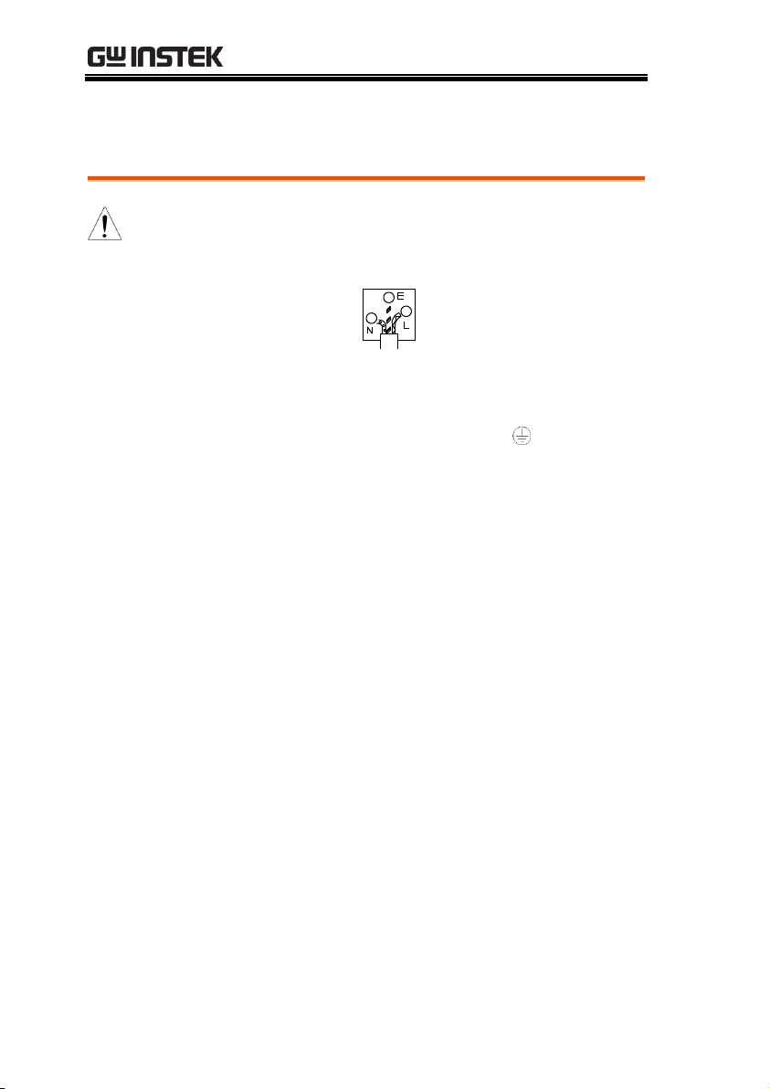
Green/ Yellow:
Earth
Blue:
Neutral
Brown:
Live (Phase)
Power cord for the United Kingdom
When using the instrument in the United Kingdom, make sure the
power cord meets the following safety instructions.
NOTE: This lead/appliance must only be wired by competent persons
WARNING: THIS APPLIANCE MUST BE EARTHED
IMPORTANT: The wires in this lead are coloured in accordance with the
following code:
As the colours of the wires in main leads may not correspond with the
coloured marking identified in your plug/appliance, proceed as follows:
The wire which is coloured Green & Yellow must be connected to the Earth
terminal marked with either the letter E, the earth symbol or coloured
Green/Green & Yellow.
The wire which is coloured Blue must be connected to the terminal which is
marked with the letter N or coloured Blue or Black.
The wire which is coloured Brown must be connected to the terminal
marked with the letter L or P or coloured Brown or Red.
If in doubt, consult the instructions provided with the equipment or contact
the supplier.
This cable/appliance should be protected by a suitably rated and approved
HBC mains fuse: refer to the rating information on the equipment and/or
user instructions for details. As a guide, a cable of 0.75mm2 should be
protected by a 3A or 5A fuse. Larger conductors would normally require
13A types, depending on the connection method used.
Any exposed wiring from a cable, plug or connection that is engaged in a
live socket is extremely hazardous. If a cable or plug is deemed hazardous,
turn off the mains power and remove the cable, any fuses and fuse
assemblies. All hazardous wiring must be immediately destroyed and
replaced in accordance to the above standard.
8
Page 9

GETTING STARTED
Model name
Bandwidth
Max differential voltage
GDP-025
25MHz
450Vrms
GDP-050
50MHz
6500Vrms
GDP-100
100MHz
6500Vrms
Features
The GDP Series differential probes provide a
safe means to measure differential voltages for
all models of oscilloscopes.
The differential probes convert high voltages
(7000 peak for GDP-050, GDP-100) into low
voltages (≤7V with ref to ground) for display on
oscilloscopes.
The GDP Series is designed to operate with the
1MΩ impedance oscilloscopes. When combined
with a 50Ω load, the attenuation will be 2 times.
Accessories
GDP-025
AC Adapter (110V or 220V depending on
region)
BNC to BNC cable: 50Ω resistance, RG58C UL,
100cm
Banana plug to banana plug silicon wire, UL
6kV, 18AWG, Length 60cm. (red x1, black x1)
IC clip, UL 1000V CAT III (red x1, black x1)
Alligator clip, UL 1000V CATII, 10A (red x1,
GETTING STARTED
The Getting Started chapter introduces the probe’s
features, appearance and functions.
Main Features
9
Page 10

GDP Series User Manual
black x1)
Accessories
GDP-050
Adapter (110V or 220V depending on region)
BNC to BNC cable: 50Ω resistance, RG58C UL,
100cm
Banana plug to banana plug silicon wire, UL
20kV, 18AWG, Length 60cm. (red x1, black x1)
HV IC clip, Max 6500V (DC+ACp-p) (red x1,
black x1)
Alligator clip, UL 1000V CATII, 10A (red x1,
black x1)
Accessories
GDP-100
Adapter (110V or 220V depending on region)
BNC to BNC cable: 50Ω resistance, RG58C UL,
100cm
Banana plug to banana plug silicon wire, UL
20kV, 18AWG, Length 60cm. (red x1, black x1)
Test lead UL 1000V, CATIII (red x1, black x1)
HV IC clip, Max 6500V (DC+ACp-p) (red x1,
black x1)
Alligator clip, UL 1000V CATII, 10A (red x1,
black x1)
10
Page 11
GETTING STARTED
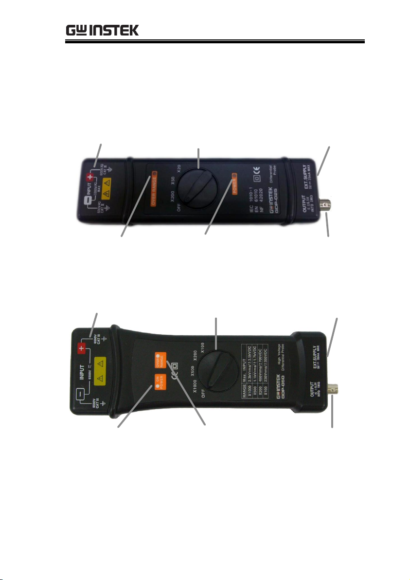
Intput terminals
Over range indicator
Attenuation
function switch
Power indicator
Power supply
input
Output
Intput terminals
Power indicator
Attenuation
function switch
Over range
indicator
Power supply
input
Output
Instrument Overview
GDP-025
GDP-050/ GDP-100
11
Page 12

GDP Series User Manual
Input terminals
Category III input terminals.
Power Indicator
The power indicator lights when the external
power supply is connected.
Over range
indicator
The over range indicator lights when the input
voltage exceeds rating.
Power supply
input
External power supply input. 9V, 200mA.
Output
Differential probe output.
≤±6.5V into 1MΩ.
12
Page 13
MEASUREMENT
High voltage
Risk of electric shock. The GDP Series differential
voltage probes are designed for use with high
voltages. When operating with high voltages
ensure proper safety precautions are taken at all
times. Please see the safety section for more details.
Connection
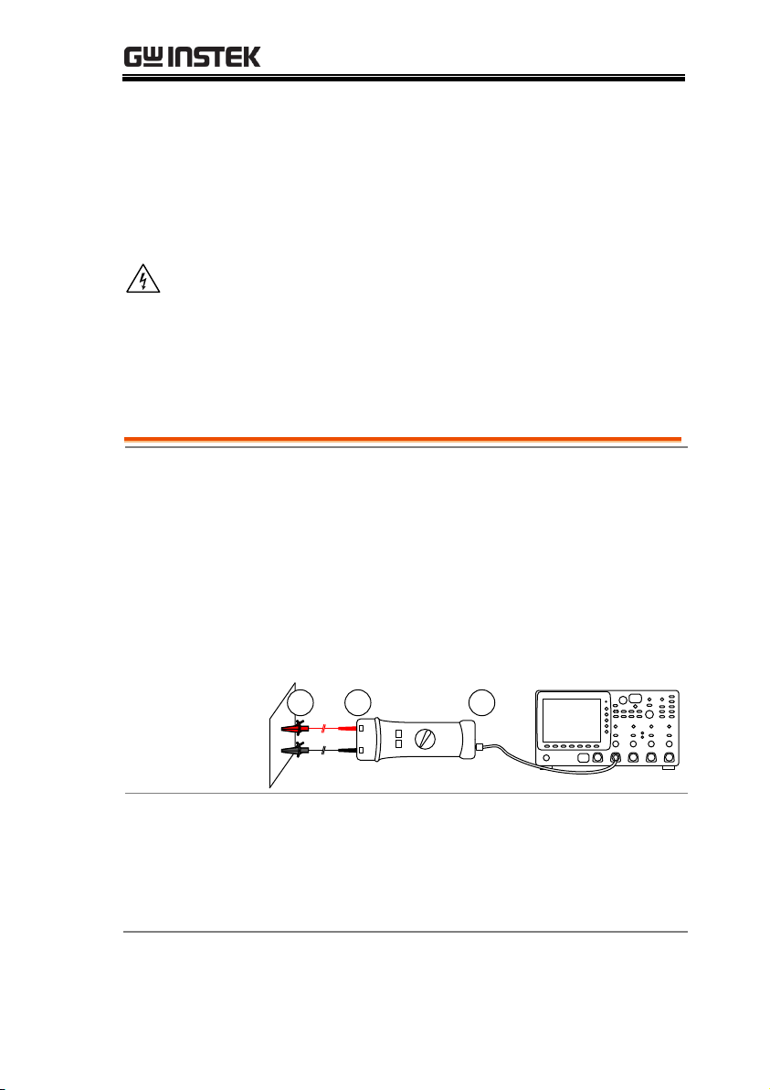
1. Connect the test leads to the GDP differential
probe INPUT terminal. Connect the low
potential to the negative terminal. Connect the
high potential to the positive terminal.
2. Connect the test lead to the EUT.
3. Connect the probe to the oscilloscope using the
BNC to BNC cable.
+-
312
Procedure
1. Adjust the vertical position on the oscilloscope.
2. Adjust the attenuation ratio and vertical
deviation in accordance to the deviation table
listed on the next page.
MEASUREMENT
Operation
13
Page 14
GDP Series User Manual
Caution
The power light must come on
Ensure the range light does not come on before
measuring
Deviation Table
Model
GDP-050
GDP-100
GDP-050
GDP-100
All
GDP-050
GDP-100
GDP-025
GDP-025
Attenuation
X 1000
X 500
X 200
X 100
X 50
X 20
Voltage input range
(DC + AC Peak)
7000 Vp-p
(±35 00 Vdc)
3500 Vp-p
(±1750 Vdc)
1400 Vp-p
(±70 0Vdc)
700 Vp-p
(±35 0Vdc)
350 Vp-p
(±175Vdc)
140 Vp- p
(±70Vdc)
Vertical Deviation
on the
Oscilloscope in
V/div
Real Division in V/div
X 1000
X 500
X 200
X 100
X 50
X 20
Model
GDP-050
GDP-100
GDP-050
GDP-100
All
GDP-050
GDP-100
GDP-025
GDP-025
1
1000
500
200
100
50
20
0.5
500
250
100
50
25
10
0.2
200
100
40
20
10
4
0.1
100
50
20
10 5 2
50m
50
25
10 5 2.5
1
20m
20
10 4 2 1 0.4
10m
10 5 2 1 .5
0.2
5m
5
2.5 1 0.5
0.25
0.1
2m
2 1 0.4
0.2
0.1
40m
Note
The real vertical deviation in V/div is equal to the
attenuation factor multiplied by the range of the
vertical deviation selected on the oscilloscope. The
real vertical deviation will be doubled if a 50Ω load is
used.
14
Page 15

MEASUREMENT
Example
With the probe set to a factor of X200, the oscilloscope
set to a vertical deviation of 0.5V/div, the real vertical
deviation is 200 x 0.5 = 100V/div. With a 50Ω load on
the input of the oscilloscope the deviation becomes
200 V/div.
15
Page 16

GDP Series User Manual
GDP-025
Bandwidth
DC-25MHz (-3dB)for x50, x200
DC-50MHz (for attenuation x20)
Attenuation
x20, x50, x200
Accuracy
± 2%
Voltage Input
Range (DC+AC
peak to peak)
≤ 140Vp-p for x20 (≅ 45Vrms)
≤ 350Vp-p for x50 (≅ 110Vrms)
≤ 1400Vp-p for x200 (≅ 450Vrms)
Permitted Max
Input Voltage
Max differential voltage: 1400 V (DC+AC
peak to peak) or 450 Vrms
Max voltage between each input terminal
and ground: 600 Vrms
Input Impedance
Differential: 4MΩ/1.2pF
Between terminals and ground:
2MΩ/2.3pF
Output
≤ ±7.0V
Output
Impedance
50Ω
Rise Time
14ns for x50, and x200; 23.4ns for x20
Rejection Rate on
Common Mode
60Hz: >80dB; 100Hz: >60dB; 1MHz:
>50dB
Power Supply
External 9V DC power supply
Consumption
Max. 35mA (0.4 Watt)
Environmental
Operating
Conditions
Indoor Use only.
Temperature: Reference: +20˚C to
+30˚C; Use: 0˚C to +50˚C; Storage: -30˚C
to +70˚C
Relative Humidity: Reference: ≤70%;
Use: 10% to 85%: 10% to 90%
Storage: 10% to 90%
Dimensions and
Weight
195mm x 55mm x 30mm: 250g
APENDIX
GDP Series Specifications
16
Page 17

APENDIX
Electrical Safety to
IEC 1010-1
Dual Insulation
Installation Category III
Degree of Pollution 2
Rated Voltage or Max Line-Earth:
600Vrms
17
Page 18

GDP Series User Manual
GDP-050
Bandwidth
DC-50MHz (-3dB)for x200, x500, x1000
DC-25MHz (for attenuation x100)
Attenuation
X100, x200, x500, x1000
Accuracy
± 2%
Voltage Input
Range (DC+AC
peak to peak)
≤ 700Vp-p for x100 (≅230Vrms)
≤ 1400Vp-p for x200 (≅460Vrms)
≤ 3500Vp-p for x500 (≅1140Vrms)
≤ 7000Vp-p for x1000 (≅2300Vrms)
Permitted Max
Input Voltage
Max differential voltage: 7000 V (DC+AC
peak to peak)
Max voltage between each input terminal
and ground: 6500 Vrms
Input Impedance
Differential: 54MΩ/1.2pF
Between terminals and ground:
27MΩ/2.3pF
Output
≤ ±7.0V
Output
Impedance
50Ω
Rise Time
7ns for x200, x500 and x1000; 14ns for
x100
Rejection Rate on
Common Mode
60Hz: >80dB; 100Hz: >60dB; 1MHz:
>50dB
Power Supply
External 9V DC power supply
Consumption
Max. 35mA (0.4 Watt)
Environmental
Operating
Conditions
Indoor Use only.
Temperature: Reference: +20˚C to
+30˚C; Use: 0˚C to +50˚C; Storage: -30˚C
to +70˚C
Relative Humidity: Reference: ≤70%;
Use: 10% to 85%: 10% to 90%
Storage: 10% to 90%
Dimensions and
Weight
240mm x 80mm x 30mm: 280g
Electrical Safety to
IEC 1010-1
Dual Insulation
Installation Category III
Degree of Pollution 2
Rated Voltage or Max Line-Earth:
6500Vrms
18
Page 19

APENDIX
GDP-100
Bandwidth
DC-100MHz (-3dB)for x200, x500, x1000
DC-50MHz (for attenuation x100)
Attenuation
X100, x200, x500, x1000
Accuracy
± 2%
Voltage Input
Range (DC+AC
peak to peak)
≤ 700Vp-p for x100 (≅230Vrms)
≤ 1400Vp-p for x200 (≅460Vrms)
≤ 3500Vp-p for x500 (≅1140Vrms)
≤ 7000Vp-p for x1000 (≅2300Vrms)
Permitted Max
Input Voltage
Max differential voltage: 7000 V (DC+AC
peak to peak)
Max voltage between each input terminal
and ground: 6500 Vrms
Input Impedance
Differential: 54MΩ/1.2pF
Between terminals and ground:
27MΩ/2.3pF
Output
≤ ±7.0V
Output
Impedance
50Ω
Rise Time
3.5ns for x200, x500 and x1000; 7ns for
x100
Rejection Rate on
Common Mode
60Hz: >80dB; 100Hz: >60dB; 1MHz:
>50dB
Power Supply
External 9V DC power supply
Consumption
Max. 35mA (0.4 Watt)
Environmental
Operating
Conditions
Indoor Use only.
Temperature: Reference: +20˚C to
+30˚C; Use: 0˚C to +50˚C; Storage: -30˚C
to +70˚C
Relative Humidity: Reference: ≤70%;
Use: 10% to 85%: 10% to 90%
Storage: 10% to 90%
Dimensions and
Weight
240mm x 80mm x 30mm: 280g
Electrical Safety to
IEC 1010-1
Dual Insulation
Installation Category III
Degree of Pollution 2
Rated Voltage or Max Line-Earth:
6500Vrms
19
Page 20
GDP Series User Manual
We
GOOD WILL INSTRUMENT CO., LTD.
No.7-1, Jhongsing Rd., Tucheng Dist., New Taipei City 236, Taiwan
GOOD WILL INSTRUMENT (SUZHOU) CO., LTD.
No. 69, Lushan Road, Suzhou New District Jiangsu, China
declares that the below mentioned product
GDP-025, GDP-050, GDP-100
Are herewith confirmed to comply with the requirements set out in the
Council Directive on the Approximation of the Law of Member States
relating to Electromagnetic Compatibility (89/336/EEC, 92/31/EEC,
93/68/EEC) and Low Voltage Equipment Directive (2006/95/EC). For
the evaluation regarding the Electromagnetic Compatibility and Low
Voltage Equipment Directive, the following standards were applied:
◎ EMC
EN 61326-1 :
Electrical equipment for measurement, control and laboratory
use –– EMC requirements (1997+A1 : 1998+A2 : 2003)
Conducted and Radiated Emissions
EN 61326: 1997+A1: 1998+A2:2 003 Class B
Electrostatic Discharge
IEC 61000-4-2: 1995+A1 : 1998+A2 : 2000
Current Harmonic
EN 61000-3-2: 2006
Radiated Immunity
IEC 61000-4-3: 2002+A1: 2002
Voltage Fluctuation
EN 61000-3-3: 1995+A1: 2001+A2 : 2005
Electrical Fast Transients
IEC 61000-4-4: 2004
-------------------------
Surge Immunity
IEC 61000-4-5: 1995+A1 : 2000
-------------------------
Conducted Susceptibility
IEC 61000-4-6: 2003+A1: 2004
-------------------------
Voltage Dips/ Interrupts
IEC 61000-4-11: 2004
◎ Safety
Low Voltage Equipment Directive 2006/95/EC
Safety Requirements
IEC/EN 61010-031: 2002+A1: 2008
EC Declaration of Conformity
20
 Loading...