

Page 1

Dual Measurement Multimeter
GDM-8351
USER MANUAL
GW INSTEK PART NO. 82DM-83510E01
ISO-9001 CERTIFIED MANUFACTURER
Page 2

This manual contains proprietary information, which is protected by
copyright. All rights are reserved. No part of this manual may be
photocopied, reproduced or translated to another language without
prior written consent of Good Will company.
The information in this manual was correct at the time of printing.
However, Good Will continues to improve products and reserves the
rights to change specification, equipment, and maintenance
procedures at any time without notice.
Good Will Instrument Co., Ltd.
No. 7-1, Jhongsing Rd., Tucheng Dist., New Taipei City 236, Taiwan.
Page 3

Table of Contents
Table of Contents
SAFETY INSTRUCTIONS ................................................... 5
GETTING STARTED ......................................................... 10
Characteristics .......................................... 11
Appearance ............................................... 13
Set Up ....................................................... 23
OPERATION .................................................................... 28
Basic Measurement Overview ................... 30
AC/DC Voltage Measurement .................... 32
AC/DC Current Measurement ................... 37
Resistance Measurement .......................... 42
Diode Test ................................................ 45
Capacitance Measurement ........................ 46
Continuity Test .......................................... 48
Frequency/Period Measurement ............... 51
Temperature Measurement ....................... 53
Dual Measurement Overview .................... 57
Advanced Measurement Overview ............ 62
dBm/dB/W Measurement ......................... 63
Max/Min Measurement ............................. 66
Relative Measurement .............................. 67
Hold Measurement ................................... 69
Compare Measurement ............................. 70
Math Measurement ................................... 72
SYSTEM/DISPLAY CONFIGURATION .............................. 76
View Serial Number .................................. 77
View Version Number ............................... 77
Brightness Settings ................................... 78
Input Resistance Settings ......................... 79
3
Page 4

GDM-8351 User Manual
Frequency/Period Input Jack Settings ........ 80
Digital Filter .............................................. 81
Restore Factory Default Settings ............... 85
Trigger ...................................................... 86
DIGITAL I/O .................................................................... 88
Digital I/O Overview ................................. 89
REMOTE CONTROL ........................................................ 93
Configure Remote Control Interface .......... 94
Return to Local Control ............................. 98
COMMAND OVERVIEW .................................................. 99
Command Syntax ...................................... 99
Command List ......................................... 103
FAQ ............................................................................... 138
APPENDIX ..................................................................... 139
System Menu Tree ................................... 139
Factory Default Settings .......................... 140
Replacing the AC Source Fuse ................. 141
Replacing the Input Fuse......................... 142
Status system ......................................... 144
Specifications ......................................... 145
Additional Specifications ........................ 150
Dimensions ............................................ 156
Declaration of Conformity ....................... 157
INDEX ............................................................................ 158
4
Page 5
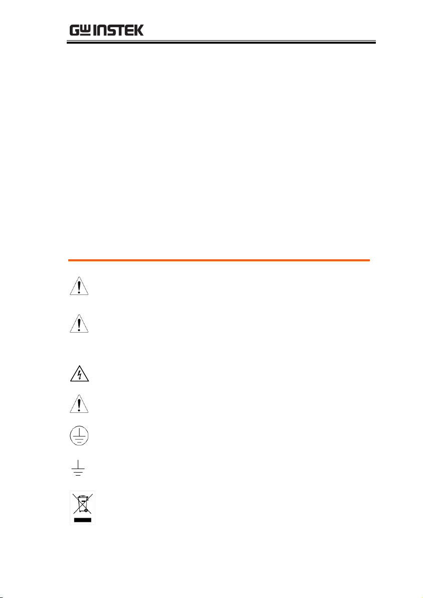
SAFETY INSTRUCTIONS
WARNING
Warning: Identifies conditions or practices that
could result in injury or loss of life.
CAUTION
Caution: Identifies conditions or practices that
could result in damage to the DMM or to other
properties.
DANGER High Voltage
Attention Refer to the Manual
Protective Conductor Terminal
Earth (ground) Terminal
Do not dispose electronic equipment as unsorted
municipal waste. Please use a separate collection
facility or contact the supplier from which this
instrument was purchased.
SAFETY INSTRUCTIONS
This chapter contains important safety instructions that you
must follow during operation and storage. Read the following
before any operation to ensure your safety and to keep the
instrument in the best possible condition.
Safety Symbols
These safety symbols may appear in this manual or on the
instrument.
5
Page 6
GDM-8351 User Manual
General Guideline
CAUTION
Make sure that the voltage input level does not
exceed DC1000V/AC750V.
Make sure the current input level does not
exceed 12A.
Do not place any heavy object on the
instrument.
Avoid severe impact or rough handling that can
lead to damaging the instrument.
Do not discharge static electricity to the
instrument.
Use only mating connectors, not bare wires, for
the terminals.
Do not block or obstruct the cooling fan vent
opening.
Do not perform measurement at the source of a
low-voltage installation or at building
installations (Note below).
Do not disassemble the instrument unless you
are qualified as service personnel.
Make sure that the COM terminal to earth is
limited to 500Vpk.
Remove all test leads before disconnecting the
mains power cord from the socket.
(Note) EN 61010-1:2010 specifies the measurement categories and
their requirements as follows. The GDM-8351 falls under category II
600V.
Measurement category IV is for measurement performed at the
source of low-voltage installation.
Measurement category III is for measurement performed in the
building installation.
Measurement category II is for measurement performed on the
circuits directly connected to the low voltage installation.
Safety Guidelines
6
Page 7
SAFETY INSTRUCTIONS
Power Supply
WARNING
AC Input voltage: 100/120/220/240 V AC
50/60Hz
The power supply voltage should not fluctuate
more than 10%.
Connect the protective grounding conductor of
the AC power cord to an earth ground, to avoid
electrical shock.
Fuse
WARNING
Fuse type: 0.125AT 100/120VAC
0.063AT 220/240 VAC
Make sure the correct type of fuse is installed
before power up.
To avoid risk of fire, replace the fuse only with
the specified type and rating.
Disconnect the power cord before fuse
replacement.
Make sure the cause of a fuse blowout is fixed
before fuse replacement.
Cleaning the
Instrument
Disconnect the power cord before cleaning.
Use a soft cloth dampened in a solution of mild
detergent and water. Do not spray any liquid.
Do not use chemicals containing harsh material
such as benzene, toluene, xylene, and acetone.
Operation
Environment
Location: Indoor, no direct sunlight, dust free,
almost non-conductive pollution (Note below)
Temperature: 0°C to 50°C
Humidity: 0~35°C : < 90%RH
>35°C: <80%RH
Altitude: <2000m
7
Page 8
GDM-8351 User Manual
(Note) EN 61010-1:2010 specifies the pollution degrees and their
requirements as follows. The GDM-8351 falls under degree 2.
Pollution refers to “addition of foreign matter, solid, liquid, or
gaseous (ionized gases), that may produce a reduction of
dielectric strength or surface resistivity”.
Pollution degree 1: No pollution or only dry, non-conductive
pollution occurs. The pollution has no influence.
Pollution degree 2: Normally only non-conductive pollution
occurs. Occasionally, however, a temporary conductivity caused
by condensation must be expected.
Pollution degree 3: Conductive pollution occurs, or dry, non-
conductive pollution occurs which becomes conductive due to
condensation which is expected. In such conditions, equipment
is normally protected against exposure to direct sunlight,
precipitation, and full wind pressure, but neither temperature
nor humidity is controlled.
Storage
environment
Location: Indoor
Temperature: -40°C to 70°C
Humidity: 0~35°C: <90%RH
>35°C: <80%RH
Disposal
Do not dispose this instrument as unsorted
municipal waste. Please use a separate collection
facility or contact the supplier from which this
instrument was purchased. Please make sure
discarded electrical waste is properly recycled to
reduce environmental impact.
8
Page 9
SAFETY INSTRUCTIONS
Green/ Yellow:
Earth
Blue:
Neutral
Brown:
Live (Phase)
Power cord for the United Kingdom
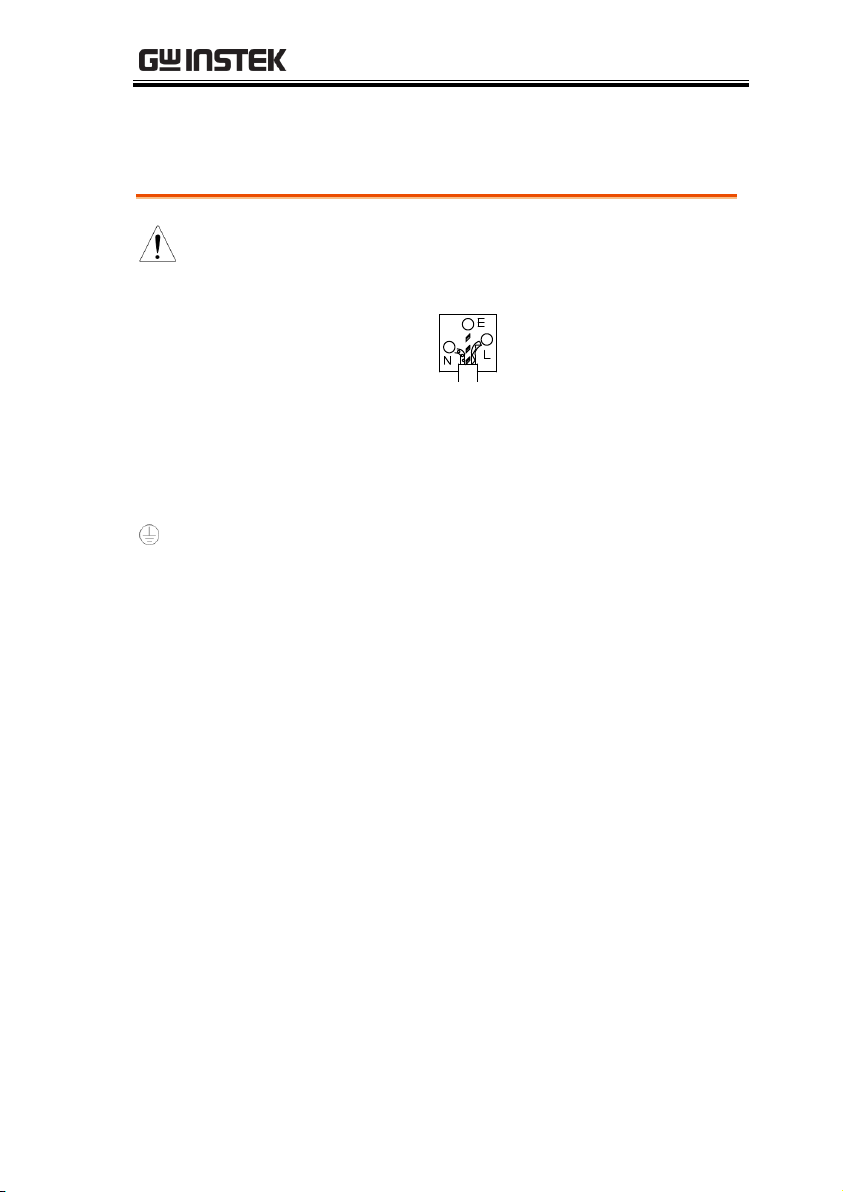
When using the unit in the United Kingdom, make sure the power
cord meets the following safety instructions.
NOTE: This lead/appliance must only be wired by competent persons
WARNING: THIS APPLIANCE MUST BE EARTHED
IMPORTANT: The wires in this lead are coloured in accordance with the
following code:
As the colours of the wires in main leads may not correspond with
the coloured marking identified in your plug/appliance, proceed
as follows:
The wire which is coloured Green & Yellow must be connected to
the Earth terminal marked with either the letter E, the earth symbol
or coloured Green/Green & Yellow.
The wire which is coloured Blue must be connected to the terminal
which is marked with the letter N or coloured Blue or Black.
The wire which is coloured Brown must be connected to the
terminal marked with the letter L or P or coloured Brown or Red.
If in doubt, consult the instructions provided with the equipment
or contact the supplier.
This cable/appliance should be protected by a suitably rated and
approved HBC mains fuse: refer to the rating information on the
equipment and/or user instructions for details. As a guide, a cable
of 0.75mm2 should be protected by a 3A or 5A fuse. Larger
conductors would normally require 13A types, depending on the
connection method used.
Any exposed wiring from a cable, plug or connection that is
engaged in a live socket is extremely hazardous. If a cable or plug is
deemed hazardous, turn off the mains power and remove the cable,
any fuses and fuse assemblies. All hazardous wiring must be
immediately destroyed and replaced in accordance to the above
standard.
9
Page 10

GDM-8351 User Manual
Characteristics ................................................................ 11
Accessories ................................................................. 12
Appearance ..................................................................... 13
GDM-8351 Front Panel .............................................. 13
Display Overview ....................................................... 19
Rear Panel .................................................................. 21
Set Up ............................................................................. 23
Tilting the Stand ......................................................... 23
Power Up .................................................................... 24
How to Use the Instrument ....................................... 25
GETTING STARTED
This chapter describes the GDM-8351 multimeter in a nutshell,
including accessories, package contents, its main features and
front / rear panel introduction.
10
Page 11

GETTING STARTED
Performance
DCV accuracy: 0.012%
High current range: 10A
High Voltage range: 1000V
High ACV frequency response: 100kHz
Features
The fastest sampling rate is (320 Readings / sec)
for ADC and PC transmission.
The diode test open-circuit voltage is ≑
6V/1mA.
120000 count display
Multiple functions: ACV, DCV, ACI, DCI, 2WR,
4WR, Cap, Freq, Period ,Temp, Continuity,
Diode test, MAX/MIN, Avg, REL, dB, dBm,
Hold, MX+B, 1/X, REF, %, Compare.
Manual or Auto ranging
AC true RMS
Data logging to PC using an Excel Add-In.
Interface
USB device port supports USBCDC and
USBTMC.
RS232
Digital I/O port can used in either pass/fail
testing (Compare function) or have the output
state remotely controlled. Only one function at a
time can be used.
Software
Excel Addins
LABVIEW driver
Characteristics
The GDM-8351 is a portable, dual-display digital multimeter
suitable for a wide range of applications, such as production testing,
research, and field verification.
11
Page 12
Accessories
Standard
Accessories
Part number
Description
82DM-83510E x1
CD-ROM (User Manual,
Software, Driver)
82DM-83511M x1
Safety Instruction Sheet
GTL-207
Test leads
Optional
Accessories
Part number
Description
GTL-246
USB Cable, USB 2.0, A-B type,
1200mm
GTL-205
Temperature Probe Adapter with
Thermal Coupling (K-type)
GDM-8351 User Manual
12
Page 13
GETTING STARTED
DCV ACV
/2W/4W
Hz/P 2ND
REL MX/MN HOLD FILTER MENU
EXIT
SHIFT
RANGE
RANGE
Enter
POWER
GDM-8351
120000 Counts Dual Measurement Multimeter
DCI ACI dB
LOCAL
REL# MATH COMP TYPE
1000V
750V
500Vpk
INPUT
FUSE
1.25A/1000V
V
W
Auto
DC + AC
TEMP
SENSE
W
4W
COM
200Vpk
H I
LO
10A 1A
CAT II 600V
dBm
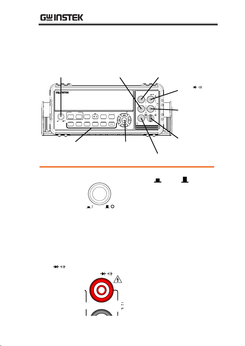
Function keys
Sense LO TerminalPower Switch
Main Display
DC/AC 1A
Terminal,
1.25A/1000V
Fuse Holder
COM
Terminal
Arrow keys
DC/AC 10A Terminal
Sense HI Terminal
V
Terminal
W
Power Switch
POWER
Turns On or Off the main
power. For the power up
sequence, see page 24.
Main Display
Shows measurement results and parameters. For
display configuration details, see page 78
(brightness setting).
For an overview of the main display, see page 19.
W
V
Input
Terminal
1000V
750V
INPUT
V
W
This terminal is used for all
measurements except for DC/AC
current measurements.
Appearance
GDM-8351 Front Panel
13
Page 14
GDM-8351 User Manual
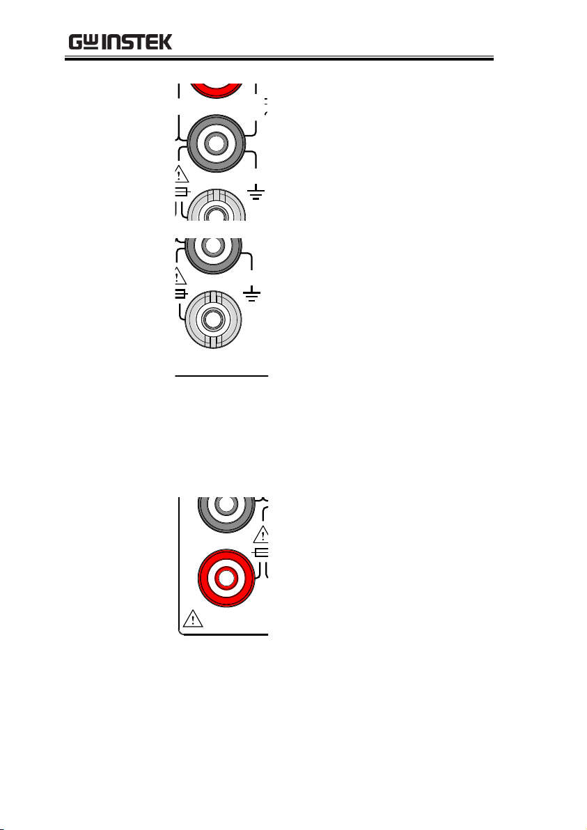
COM Terminal
1000V
750V
500Vpk
INPUT
V W
COM
Accepts ground (COM) line in all
measurements.
The maximum withstand voltage
between this terminal and earth is
500Vpk.
DC/AC 1A
Terminal
AMPS Fuse
Holder
1000V
750V
500Vpk
INPUT
FUSE
1.25A/1000V
V W
COM
Low current measurement
terminal. Accepts DC/AC Current
input. For details see page 37.
DC: 10mA~1A
AC: 10mA~1A
As a fuse, protects the instrument
from over-current. Rating: F1.25A,
1000V.(This terminal accepts
DC/AC current input)
For the fuse replacement
procedure, see page 142.
DC/AC 10A
Terminal
1000V
750V
500Vpk
INPUT
FUSE
1.25A/1000V
V W
SENSE
W 4W
COM
200Vpk
H I
LO
10A 1A
CAT II 600V
High range current measurement
terminal. Accepts DC/AC Current
input. For DCI or ACI details, see
page 37.
14
Page 15
GETTING STARTED
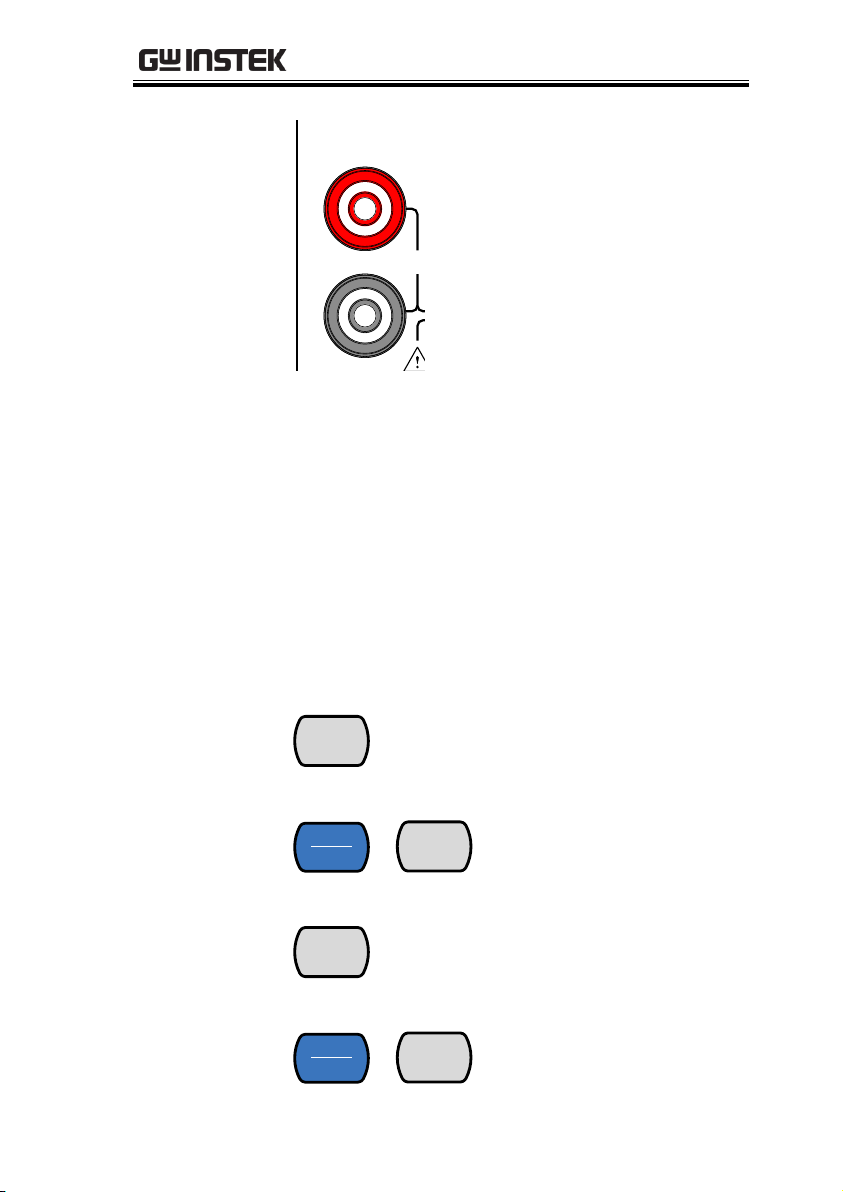
Sense HI
Terminal
1000V
750V
500Vpk
INPUT
V
W
SENSE
W
4W
COM
200Vpk
H I
LO
Accepts HI sense line in 4W
resistance measurement.
Sense LO
Terminal
Accepts LO sense line in 4W
resistance measurement.
Measurement
Keys
The top row of measurement keys are used for
basic DMM measurements such as voltage,
current, resistance, capacitance and frequency. The
bottom row of measurement functions are used for
more advanced functions.
Each key has a primary and secondary function.
The secondary function is accessed in conjunction
with the SHIFT key.
Upper Measurement keys
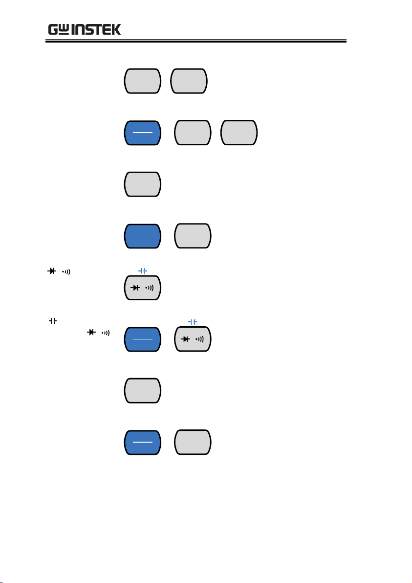
DCV
DCV
DCI
Measures DC Voltage (page 32).
DCI
(SHIFT→DCV)
SHIFT
EXIT
→
DCV
DCI
Measures DC Current (page
37).
ACV
ACV
ACI
Measures AC Voltage (page 32).
ACI
(SHIFT→ACV)
SHIFT
EXIT
→
ACV
ACI
Measures AC Current (page
37).
15
Page 16
GDM-8351 User Manual
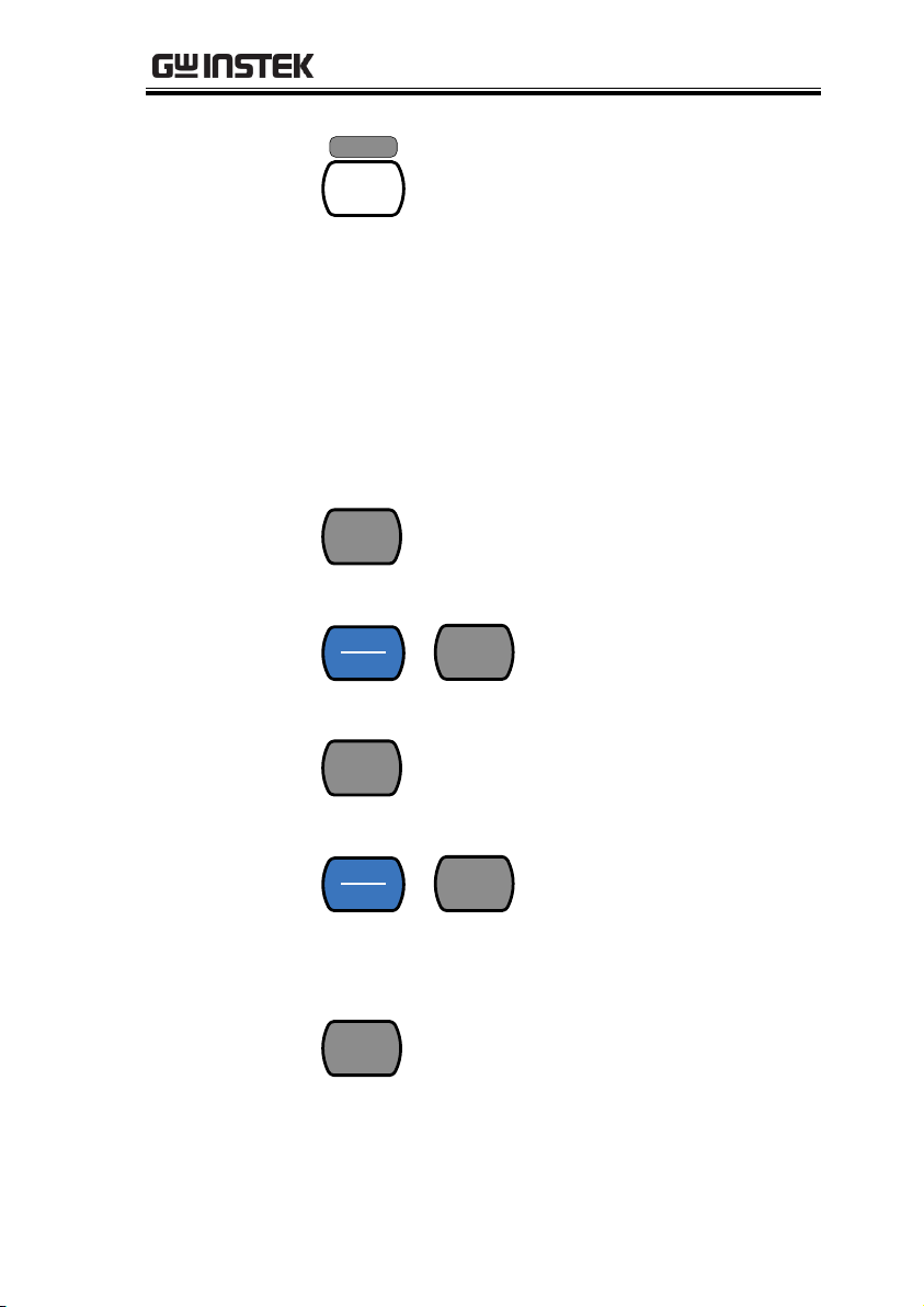
DCV + ACV
DCV
DCI
+
ACV
ACI
Measures DC + AC voltage
(page 32).
DCI+ACI
SHIFT
EXIT
→
DCV
DCI
+
ACV
ACI
Measures DC +
AC current
(page 37).
2W/4W
2W/4W
TEMP
Measures resistance (2W or 4W)
See page 42.
TEMP
(SHIFT →
2W/4W)
SHIFT
EXIT
→
2W/4W
TEMP
Measures temperature. See
page 53.
/
/
Measures diodes or continuity,
depending on the selected mode.
See page 45 and 48, respectively.
(SHIFT→
/
)
SHIFT
EXIT
→
/
Measures capacitance. See
page 46.
Hz/P
Hz/P
dB
Measures the frequency or period
of a signal, depending on the
selected mode. See page 51.
dB
(SHIFT →
Hz/P
)
SHIFT
EXIT
→
Hz/P
dB
Measures dB. See page 65.
16
Page 17
GETTING STARTED
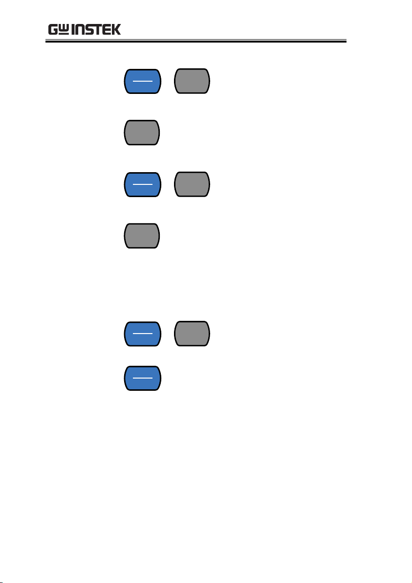
2ND
2ND
LOCAL
As the 2ND key, selects the
measurement item on the 2nd
display (page 57). Pressing and
holding for more than 1 second
turns off the 2nd display.
As the Local key, releases the unit
from remote control and returns
the instrument to local panel
operation (page 97).
Lower Measurement keys
REL
REL
REL#
Measures the Relative value (page
67).
REL#
(SHIFT→REL)
SHIFT
EXIT
→
REL
REL#
Manually sets the reference
value for the Relative value
measurement.
MX/MN
MX/MN
MATH
Measures the Maximum or the
Minimum value (page 66).
MATH
(SHIFT→
MX/MN)
SHIFT
EXIT
→
MX/MN
MATH
Enters the Math
measurement mode. The
supported math functions
include MX+B, REF% and
1/X. See page 72 for details.
HOLD
HOLD
COMP
Activates the Hold function (page
69).
17
Page 18
GDM-8351 User Manual
COMP
(SHIFT→HOLD)
SHIFT
EXIT
→
HOLD
COMP
Activates the compare
measurement function. See
page 70.
FILTER
FILTER
TYPE
Turns the digital filter on or off.
See page 81.
TYPE
(SHIFT→FILTER)
SHIFT
EXIT
→
FILTER
TYPE
Sets the type of filter and
the size of the rolling
window. See page 82.
MENU
MENU
dBm
Enters the configuration menu for
System Settings, Measurement
Settings, Temperature
measurement settings, I/O
settings, Terminal character
settings and Firmware installation.
See page 76 for the system menu.
dBm
(SHIFT→MENU)
SHIFT
EXIT
→
MENU
dBm
Measures dBm/W, see
page 63.
SHIFT/EXIT
SHIFT
EXIT
When used as a SHIFT key, it is
used to access the secondary
functions associated with the
measurement keys.
When used as an EXIT key, it will
exit out of menu systems.
18
Page 19
GETTING STARTED
AUTO/ENTER
Auto
Enter
When used as an AUTO key, it
will set the range of the selected
function to autorange.
When used as an ENTER key, it
will confirm the entered value or
menu item.
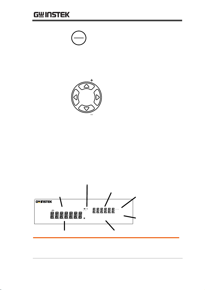
Arrow Keys
RANGE
RANGE
The arrow keys are used to
navigate the menu system and edit
values.
The Up and Down arrow keys will
also manually set the range for the
voltage and current
measurements.
The Left and Right arrow keys will
also toggle the refresh rate
between the fast, medium and
slow (F, M, S) rates.
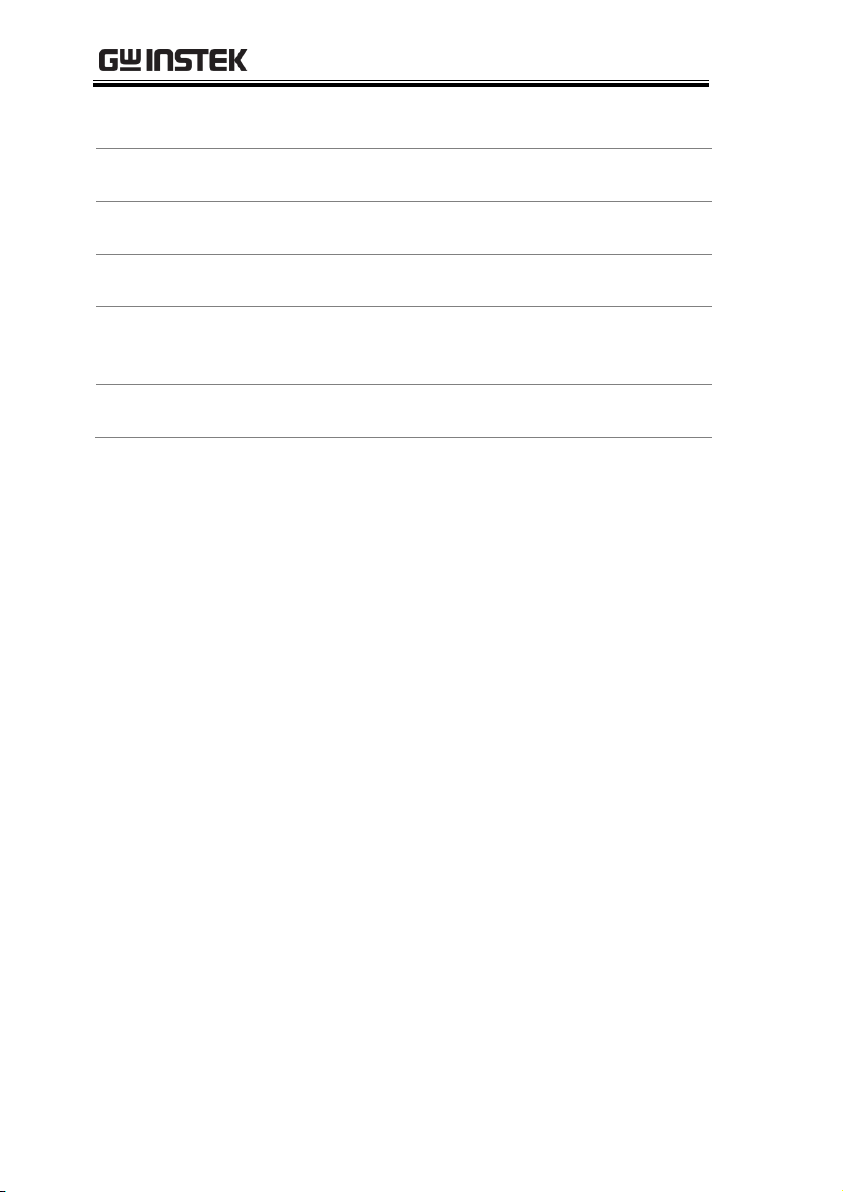
Primary Display
Secondary Display
Function status icons
Secondary
measurement units
Primary measurement units
Primary measurement
function icons
Secondary
measurement
function icons
REARGPIBUSBLANRS232FILTRCLSTOCOMP2ND
dBmEXTSHIFTERRLIMITAUTOMATH4W2WDCAC
AVmm
HzWkM
WSFC
mdB
%
AVmm
HzWkM
WSFC
RMTMAXMINRELHOLDSMFAUTO4W2WDCAC
USBSTOnμFMEMRATIO UNCAL
n μ F
120000 Counts Dual Measurement Multimeter
GDM-8351
Primary Measurement
Function Icons
Displays the primary measurement
function.
Display Overview
19
Page 20
GDM-8351 User Manual
Primary Measurement
Units
Displays the units for the primary
measurement function.
Secondary Display
Displays the results of the secondary
measurement.
Secondary Measurement
Units
Displays the units for the secondary
measurement function.
Secondary Measurement
function icons
Displays the secondary measurement
function.
Function Status Icons
Display status icons for
operations/functions that are not linked to
the primary or secondary functions.
Primary Display
Displays the results of the primary
measurement.
20
Page 21
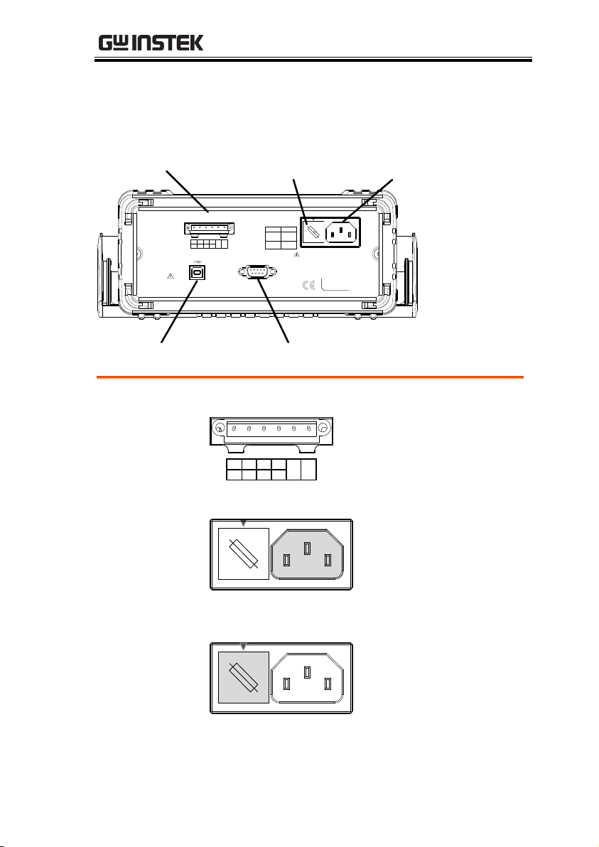
Rear Panel
USB Device Port
Power Cord
Socket
RS232 Port
Digital I/O port
100
220
120
240
SER.NO. LABEL
50 / 60 Hz
15VA MAX.
LINE RATING
FUSE LINE
100VAC
120VAC
220VAC
240VAC
0.125AT
0.063AT
TEST LEADS BEFORE REPLACING FUSE
DISCONNECT POWER CORD AND
REMOVE INPUTS BEFORE OPENING.
TO AVOID SHOCK,
WARNING
DIGITAL I / O
RS232
H.F L.F PASS EOM
SET3SET2SET1 SET4
TRIG
IN
GND
Fuse 0.125AT/
0.063AT
Digital I/O Port
DIGITAL I / O
H.F L.F PASS EOM
SET3SET2SET1 SET4
TRIG
IN
GND
The Digital I/O port is
used for outputting the
comparison test results,
external triggering and
as a user-defined output
port. See page 89.
Power Cord
Socket
100
220
120
240
Accepts the power cord.
AC 100/120/220/240V
±10%, 50/60Hz
For power on sequence,
see page 24.
Fuse Socket
100
220
120
240
Holds the main fuse:
100/120 VAC: 0.125AT
220/240 VAC: 0.063AT
For fuse replacement
details, see page 141.
GETTING STARTED
21
Page 22
GDM-8351 User Manual
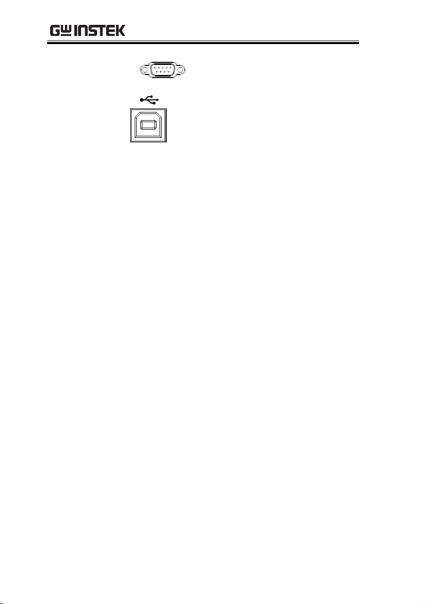
RS232
RS232
RS232 port. This port is used for
remote control. See page 94.
USB Device Port
Type B USB port. This port is used
for remote control. See page 94.
22
Page 23
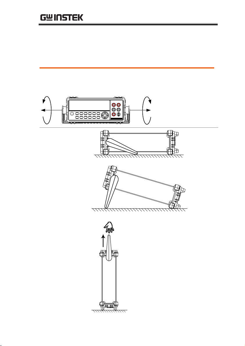
GETTING STARTED
From the base of the handle, gently pull the handle out sideways
and then rotate it to one of the following positions.
Horizontal
position
Tilt stand
position
Carry position
Set Up
Tilting the Stand
23
Page 24
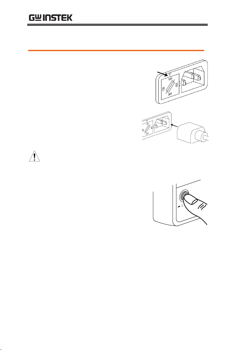
Power Up
Steps
1. Ensure the correct line
voltage is lined up with
the arrow on the fuse
holder. If not, see page 141
to set the line voltage and
fuse.
2. Connect the power
cord to the AC
voltage input.
Note
Make sure the ground connector on the power
cord is connected to a safety ground. This will
influence the measurement accuracy.
3. Push to turn on the main
power switch on the front
panel.
4. The display turns on and shows the last
function that was used before the power was
reset.
P
O
W
E
R
GDM-8351 User Manual
24
Page 25
GETTING STARTED
Background
The following section will introduce to you
how to access the basic functions on the DMM
as well as how to navigate the menu system
and edit the parameter values.
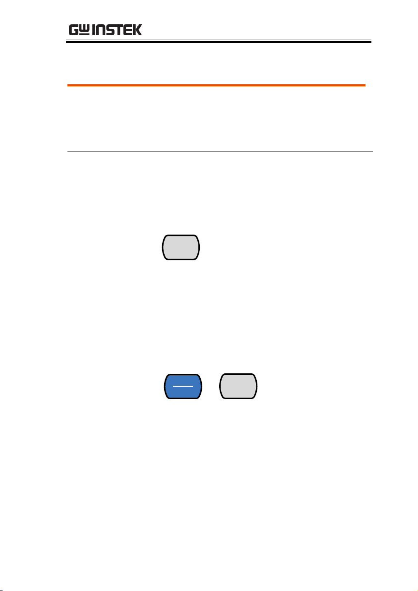
Using the
Function keys
Any of the primary functions can be used by
simply pressing the desired function key.
For example:
To activate the DCV function, press the DCV
key.
DCV
DCI
To activate a secondary function, first press the
SHIFT key followed by the function key for the
secondary function.
For example: To activate DCI measurement,
first press the SHIFT key. SHIFT will be
highlighted on the display. Next, press the
DCV function key. This will activate the DCI
mode.
SHIFT
EXIT
→
DCV
DCI
How to Use the Instrument
25
Page 26
GDM-8351 User Manual
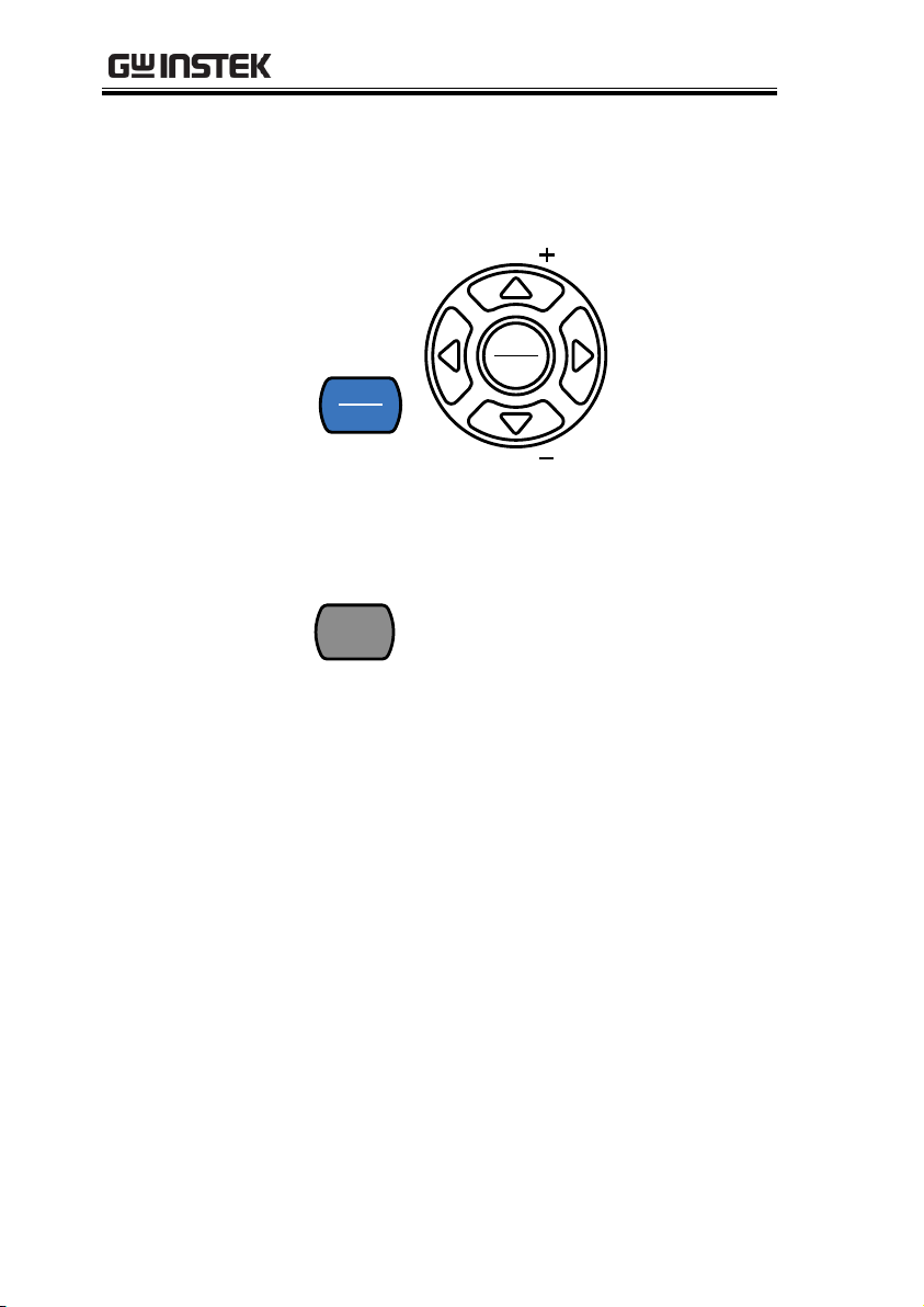
Navigating the
Menu System
The menu system is navigated with the Up,
Down, Left and Right arrow keys, the
Auto/Enter key and the SHIFT/EXIT key.
SHIFT
EXIT
Auto
Enter
RANGE
RANGE
To enter the menu system, press the MENU
key. See page 139 for the System Menu tree.
MENU
dBm
Pressing the Left and Right arrow keys will
navigate to each of the menu items on the
current menu level.
Pressing the Down key will go down to the
next level of the menu tree.
Conversely pressing the Up key will allow
you to go back to the previous menu level.
Pressing Down or Enter on the last item in
a menu tree will allow you to edit the
settings or parameters for that particular
item or setting.
Pressing the Exit key will allow you to exit
from the current settings and return to the
previous menu tree level.
26
Page 27
GETTING STARTED
Editing a Setting
or Parameter
When you access a menu or parameter setting,
the Up, Down, Left and Right keys can be used
again to edit the parameter as well.
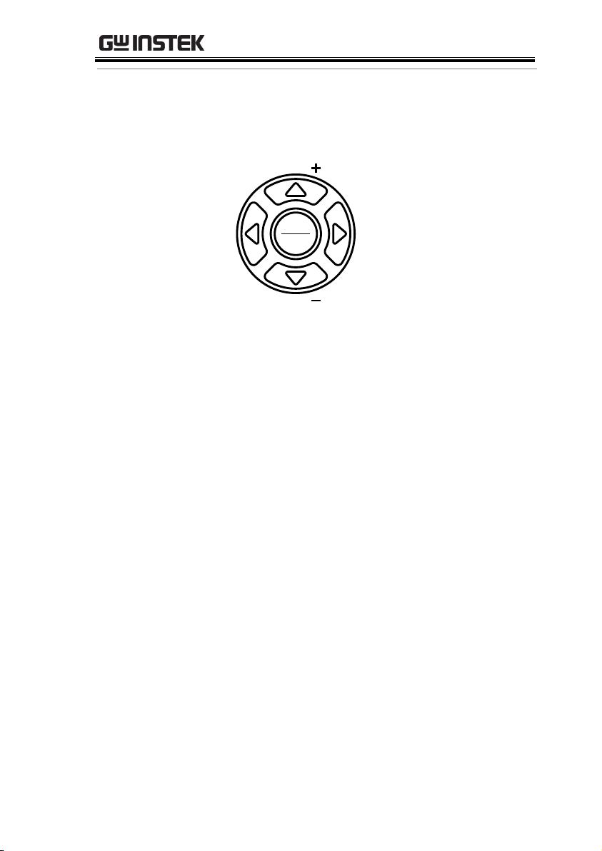
Auto
Enter
RANGE
RANGE
If a setting or parameter is flashing, it
indicates that that particular parameter can
be edited.
Pressing the Left or Right arrow key will
allow you to select a digit or character to
edit.
Pressing the Up or Down keys will allow
you to edit the selected character.
27
Page 28

GDM-8351 User Manual
Basic Measurement Overview .......................................... 30
Refresh Rate ............................................................... 30
Reading Indicator ....................................................... 31
Automatic/Manual Triggering ................................... 31
AC/DC Voltage Measurement .......................................... 32
Select the Voltage Range ........................................... 33
Voltage Conversion Table .......................................... 35
Crest Factor Table ...................................................... 36
AC/DC Current Measurement .......................................... 37
Select the Current Range ........................................... 39
Resistance Measurement ................................................. 42
Select the Resistance Range ...................................... 44
Diode Test ....................................................................... 45
Capacitance Measurement ............................................... 46
Select the Capacitance Range .................................... 47
Continuity Test ................................................................ 48
Set Continuity Threshold ........................................... 49
Continuity Beeper Settings ........................................ 50
Frequency/Period Measurement ...................................... 51
Frequency/Period Settings ........................................ 52
Temperature Measurement .............................................. 53
Set the Temperature Units ........................................ 54
Select Thermocouple Type ........................................ 55
OPERATION
28
Page 29

OPERATION
Set the Reference Junction Temperature ................... 56
Dual Measurement Overview ........................................... 57
Supported dual measurement modes ....................... 57
Using Dual Measurement Mode ............................... 58
Advanced Measurement Overview ................................... 62
Supported Advanced Measurement Functions ........ 62
dBm/dB/W Measurement ................................................ 63
dBm/dB Calculation ................................................... 63
Measuring dBm/W .................................................... 63
Measure dB ................................................................ 65
Max/Min Measurement ................................................... 66
Relative Measurement ..................................................... 67
Hold Measurement ......................................................... 69
Compare Measurement ................................................... 70
Math Measurement ......................................................... 72
Math Measurement Overview ................................... 72
Measure MX+B .......................................................... 72
Measure 1/X ............................................................... 73
Measure Percentage................................................... 74
29
Page 30
GDM-8351 User Manual
Background
The refresh rate defines how frequently the
DMM captures and updates measurement data.
A faster refresh rate yields a lower accuracy. A
slower refresh rate yields a higher accuracy.
Consider these tradeoffs when selecting the
refresh rate.
For further details, please see the specifications.
Refresh rate
(Reading/S)
Function
S M F
Continuity/Diode
10
40
320
DCV/DCI
10
40
320
ACV/ACI
10
40
320
Frequency/Period
1
9.8
83
Temperature
10
40
320
Resistance
10
40
320
Capacitance
2 2 2
Steps
1. Press the left or right arrow keys to change the
refresh rate.
2. The refresh rate will be
shown at the top of the
display.
F ↔ M ↔ S
Note
The refresh rate cannot be set for capacitance
measurement.
Basic Measurement Overview
Refresh Rate
30
Page 31
OPERATION
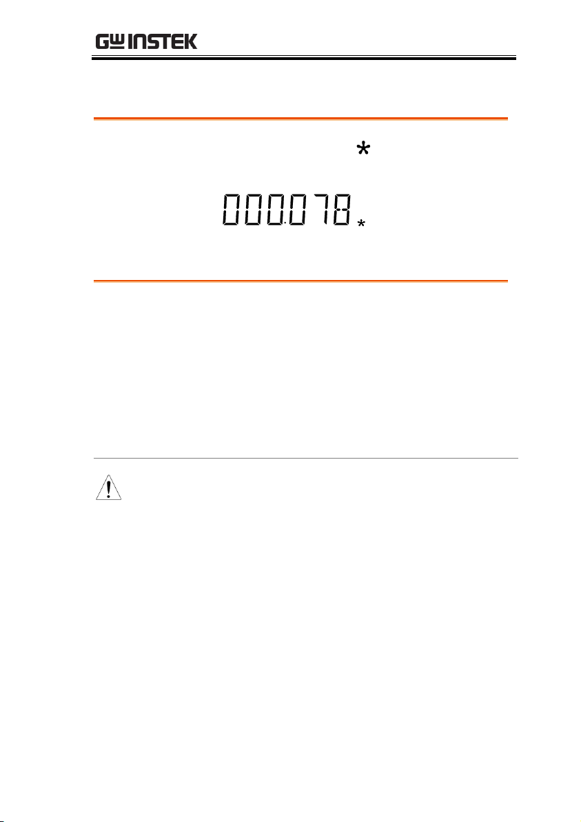
Overview
1. The reading indicator next to the 1st display
flashes according to the refresh rate setting.
V
Overview
By default, the GDM-8351 automatically
triggers according to the refresh rate. See the
previous page for refresh rate setting details.
The TRIG IN pin of the digital I/O port or the
*TRG remote command can be used to
manually trigger acquisition when the trigger
mode is set to EXT. See page 86 for trigger
setting details.
Note
Manual triggering is not supported for capacitance
measurements.
Reading Indicator
Automatic/Manual Triggering
31
Page 32
GDM-8351 User Manual
Set to ACV/DCV
Measurement
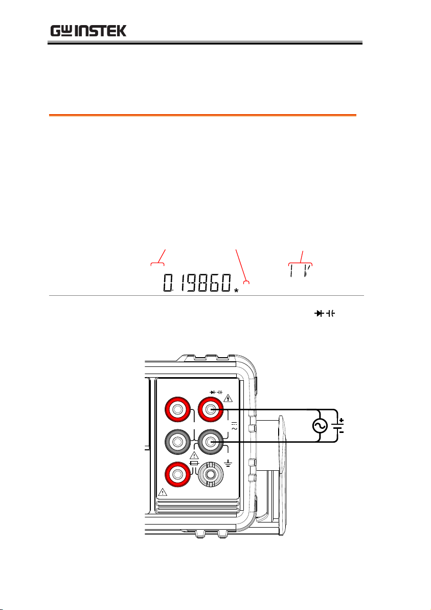
1. Press the DCV or ACV key to measure DC or
AC voltage.
For AC + DC voltage, press the ACV and DCV
keys at the same time.
2. The mode will switch to AC, DC or AC+DC
mode immediately, as shown below.
REARGPIBCVCCSWEEPFILTRCLSTOCOMP2ND
dBmEXTSHIFTERRLIMITAUTOMATH4W2WDCAC
AVmm
HzWkM
WSFC
mdB
%
AVmm
HzWkM
WSFC
RMTMAXMINRELHOLDSMFAUTO4W2WDCAC
AC & DC
indicator
Voltage
units
Measurement
range
Connection
Connect the test lead between the VΩ and
the COM terminal. The display updates the
reading.
1000V
750V
500Vpk
INPUT
FUSE
1.25A/1000V
V
W
SENSE
W
4W
COM
200Vpk
H I
LO
10A 1A
CAT II 600V
AC/DC Voltage Measurement
The GDM-8351 can measure up to 750VAC or 1000VDC, however
the CATII measurement is only rated up to 600V.
32
Page 33
OPERATION
Auto Range
To turn the automatic range selection On/Off,
press the AUTO key.
Manual Range
Press the Up or the Down key to select the
range. The AUTO indicator turns Off
automatically. If the appropriate range is
unknown, select the highest range.
Selectable Voltage
Ranges
Range
Resolution
Full scale
100mV
1μV
120mV
1V
10μV
1.2V
10V
0.1mV
12V
100V
1mV
120V
750V (AC)
10mV
765V
1000V (DC)
10mV
1020V
Note
For further details, please see the specifications on
page 145.
Note
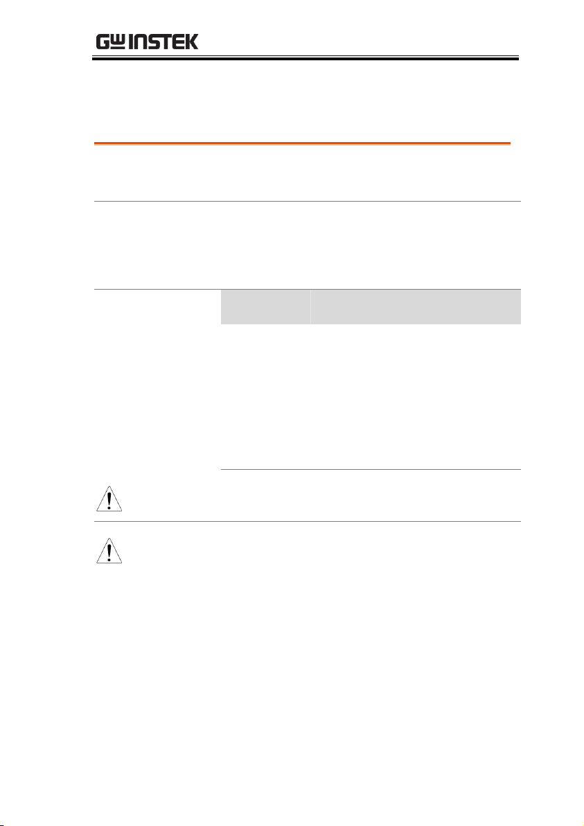
DC voltages with AC components cannot be
accurately measured if the DC+AC component
exceeds the dynamic range for the selected DC
range. Any voltage exceeding the dynamic range
will be clipped at the upper/lower range limit.
Under these conditions the range that is chosen
with the Auto range function may be too small.
Select the Voltage Range
The voltage range can be set automatically or manually.
33
Page 34
GDM-8351 User Manual
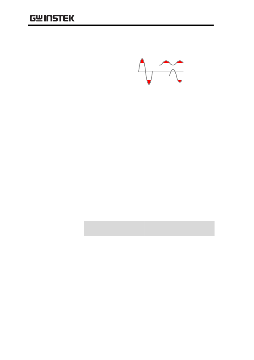
For example:
A
Dynamic Range
0V
Dynamic Range
C D
B
E
A,B: Input exceeds the dynamic range.
C,D: The DCV offset causes the input to exceed the
upper dynamic range.
E: The DCV offset causes the input to exceed the
lower dynamic range.
The DC voltage range should be manually selected
when all of the following conditions are true:
When DCV measurement is used.
When the signals being measured contain both
DC and AC components.
When the amplitude of the AC component in
the measured signal is higher or lower than the
dynamic range of the range being currently
selected by the auto-range function.
Maximum DCV
Dynamic Range
Selected DCV Range
Dynamic Range
DC 100mV
±180mVmax
DC 1V
±1.8Vmax
DC 10V
±18Vmax
DC 100V
±180Vmax
DC 1000V
±1000Vmax
34
Page 35
OPERATION
Waveform
Peak to Peak
AC (True RMS)
DC
Sine
2.828
1.000
0.000
Rectified Sine (full wave)
1.414
0.435
0.900
Rectified Sine (half wave)
2.000
0.771
0.636
Square
2.000
1.000
0.000
Rectified Square
1.414
0.707
0.707
Rectangular Pulse
2.000
2K
K=
)2
( DD
D=X/Y
2D
D=X/Y
Triangle Sawtooth
3.464
1.000
0.000
PK-PK
PK-PK
PK-PK
PK-PK
PK-PK
PK-PK
X
Y
PK-PK
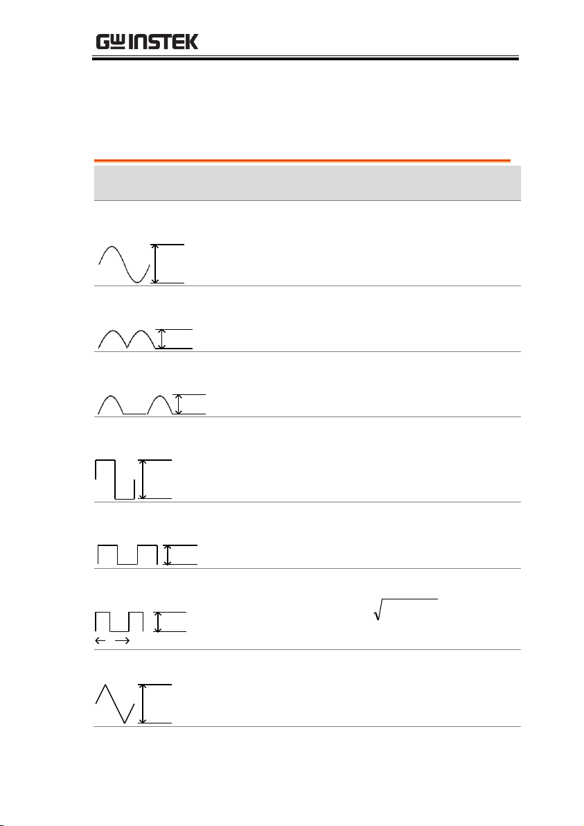
Voltage Conversion Table
This table shows the relationship between an AC and DC reading
for various waveforms.
35
Page 36
GDM-8351 User Manual
Background
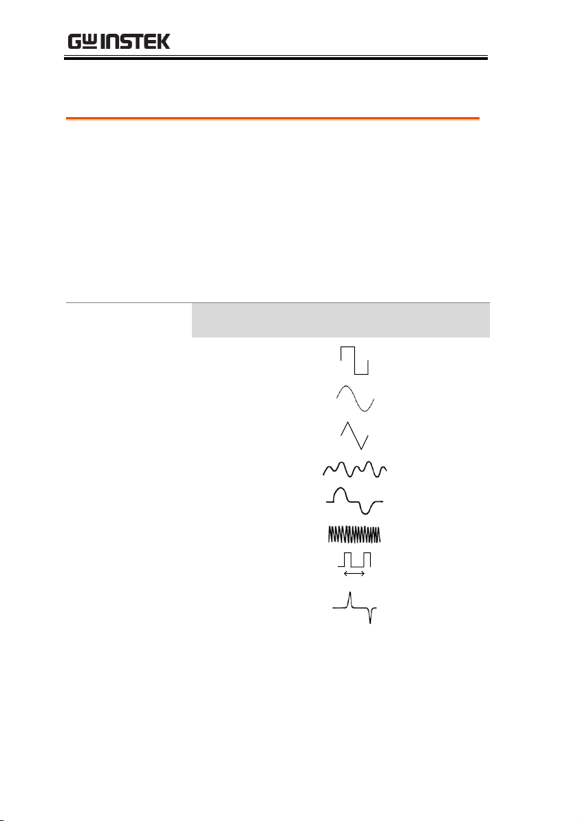
Crest factor is the ratio of the peak signal
amplitude to the RMS value of the signal. It
determines the accuracy of AC measurement.
If the crest factor is less than 3.0, voltage
measurement will not result in error due to
dynamic range limitations at full scale.
If the crest factor is more than 3.0, it usually
indicates an abnormal waveform as seen from
the below table.
Crest Factor Table
Waveform
Shape
Crest factor
Square wave
1.0
Sine wave
1.414
Triangle sawtooth
1.732
Mixed frequencies
1.414 ~ 2.0
SCR output
100% ~ 10%
1.414 ~ 3.0
White noise
3.0 ~ 4.0
AC Coupled pulse
train
>3.0
Spike
>9.0
Crest Factor Table
36
Page 37
OPERATION
Set to ACI/DCI
Measurement
1. Press SHIFT → DCV or SHIFT → ACV to
measure DC or AC current, respectively.
For AC+DC current, press SHIFT followed by
both the DCV and ACV key at the same time.
2. The mode will switch to AC, DC or AC+DC
mode immediately, as shown below.
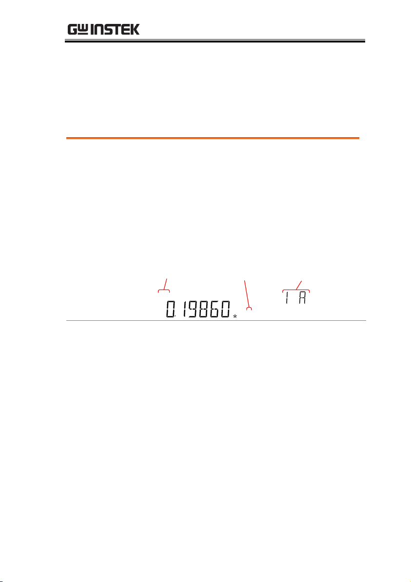
REARGPIBCVCCSWEEPFILTRCLSTOCOMP2ND
dBmEXTSHIFTERRLIMITAUTOMATH4W2WDCAC
AVmm
HzWkM
WSFC
mdB
%
AVmm
HzWkM
WSFC
RMTMAXMINRELHOLDSMFAUTO4W2WDCAC
AC & DC
indicator
Current
units
Measurement
range
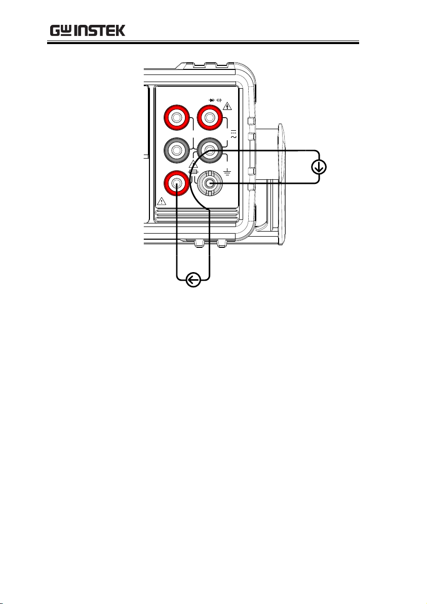
Connection
Connect the test lead between the 10A terminal
and the COM terminal or DC/AC 1A terminal
and the COM terminal, depending on the input
current.
For current ≤ 1A use the 1A terminal; For
current up to 10A use the 10A terminal. The
display updates the reading.
AC/DC Current Measurement
The GDM-8351 series DMMs have two input terminals for current
measurement. A 1A terminal for current less than 1A and a 10A
terminal for measurements up to 10A.
The units can measure 0 ~ 10A for both AC and DC current.
37
Page 38
GDM-8351 User Manual
1000V
750V
500Vpk
INPUT
FUSE
1.25A/1000V
V
W
SENSE
W
4W
COM
200Vpk
H I
LO
10A 1A
CAT II 600V
Max 1A
Max 10A
38
Page 39
OPERATION
Auto Range
To turn the automatic range selection On/Off,
press the AUTO key. The most appropriate
range for the currently used input jack will be
automatically selected. The DMM is able to do
this by remembering the last manually selected
range and using that information to determine
the smallest current range that the auto-range
function will switch to.
When the current input is switched to another
terminal, the range must be manually set.
Manual Range
Press the Up or the Down key to select the
range. The AUTO indicator turns Off
automatically. If the appropriate range is
unknown, select the highest range.
Selectable
Current Ranges
Range
Resolution
Full scale
INJACK
10mA
100nA
12mA
1A
100mA
1μA
120mA
1A
1A
100μA
1.2A
1A
10A
1mA
12A
10A
Note
For further details, please see the specifications on
page 145.
Select the Current Range
The current range can be set automatically or manually.
39
Page 40
GDM-8351 User Manual
Note
DC currents with AC components cannot be
accurately measured if the DC+AC component
exceed the dynamic range for the selected DC
range. Any current exceeding the dynamic range
will be clipped at the upper/lower range limit.
Under these conditions the range that is chosen
with the Auto range function may be too small.
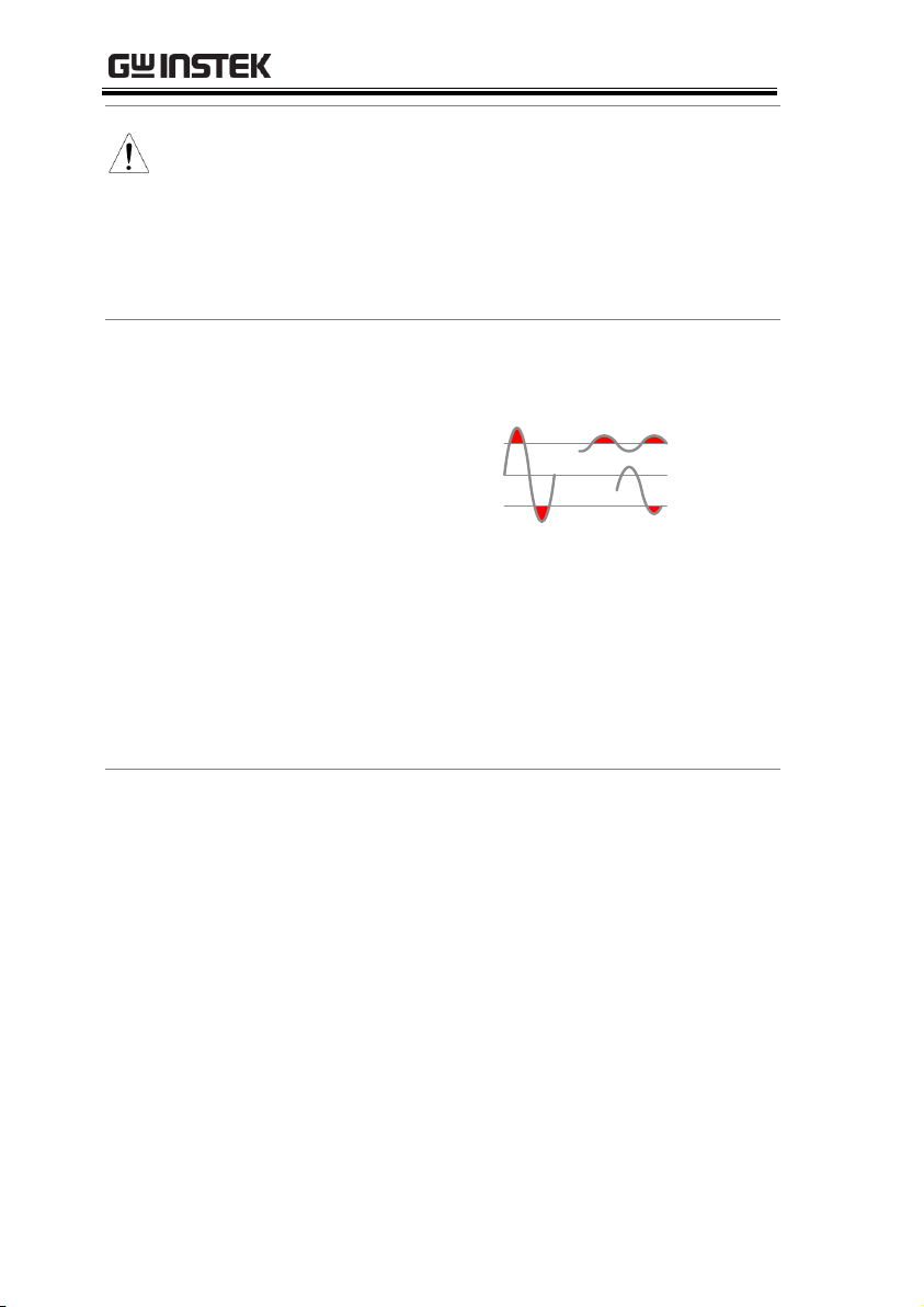
For example:
A
Dynamic Range
0A
Dynamic Range
C D
B
E
A,B: Input exceeds the dynamic range.
C,D: The DCI offset causes the input to exceed the
upper dynamic range.
E: The DCI offset causes the input to exceed the
lower dynamic range.
The DC current range should be manually selected
when all of the following conditions are true:
When DCI measurement is used.
When the signals being measured contain both
DC and AC components.
When the amplitude of the AC component in
the measured signal is higher or lower than the
dynamic range of the range being currently
selected by the auto-range function.
40
Page 41

OPERATION
Maximum DCI
Dynamic Range
Selected DCI Range
Dynamic Range
DC 10mA
± 30mA max
DC 100mA
± 300mA max
DC 1A
± 1.25A max
DC10A
± 12A max
41
Page 42
GDM-8351 User Manual
Measurement
Type
2-wire
Uses the standard V-COM ports.
Recommended for measuring
resistances larger than 1kΩ.
4-wire
Compensates the test lead effect using
the 4W compensation ports(HI/LO
sense ports), in addition to the
standard V-COM ports.
Recommended for measuring
sensitive resistances smaller than 1kΩ.
Set to 2W or 4W
Measurement
1. Press the 2W/4W key once to activate 2W
resistance measurement.
Press the 2W/4W key twice to activate 4W
resistance measurement.
2. The mode will switch to the selected resistance
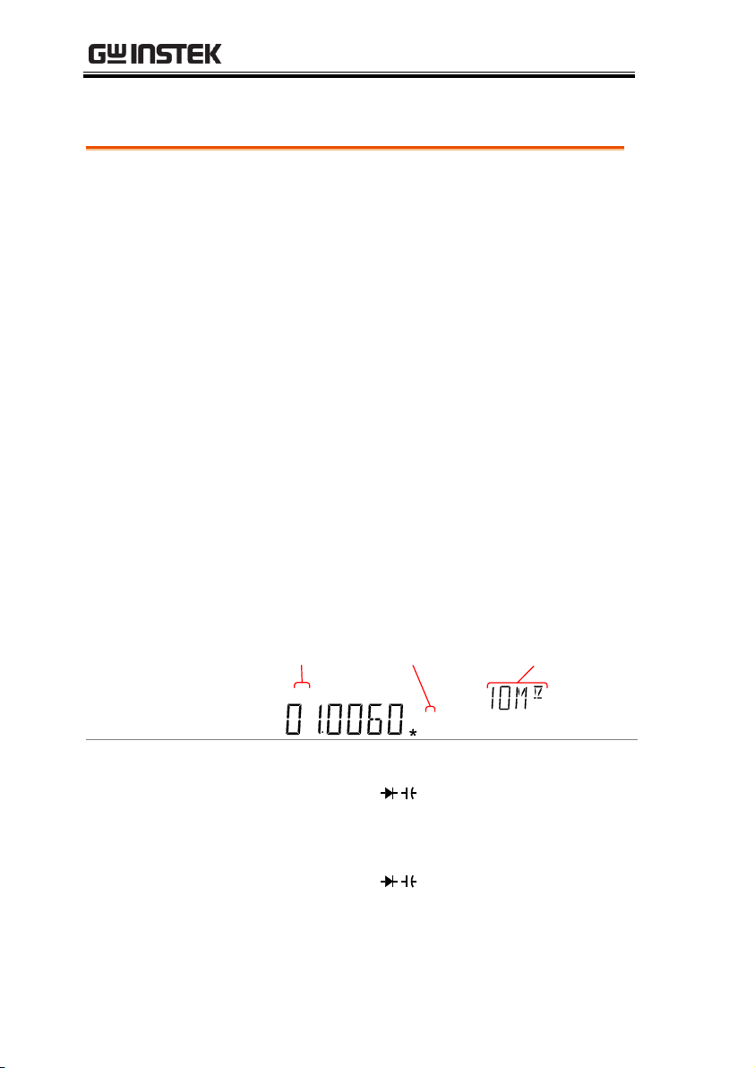
mode immediately, as shown below.
Display
REARGPIBCVCCSWEEPFILTRCLSTOCOMP2ND
dBmEXTSHIFTERRLIMITAUTOMATH4W2WDCAC
AVmm
HzWkM
WSFC
mdB
%
AVmm
HzWkM
WSFC
RMTMAXMINRELHOLDSMFAUTO4W2WDCAC
2W/4W
indicator
Resistance
units
Measurement
range
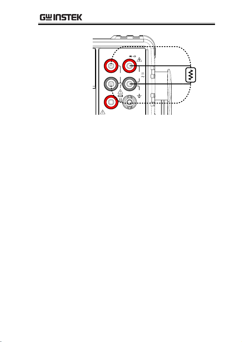
Connection
For 2W measurement, connect the test leads
between the VΩ terminal and the COM
terminal.
For 4W measurement, connect the test leads
between the VΩ terminal and the COM
terminal, as you would for 2W measurement.
Connect the sense leads between the LO and HI
sense terminals.
Resistance Measurement
42
Page 43
OPERATION
1000V
750V
500Vpk
INPUT
FUSE
V
W
SENSE
W
4W
COM
200Vpk
H I
LO
10A 1A
CAT II 600V
4W only
4W only
4W & 2W
43
Page 44
GDM-8351 User Manual
Auto Range
To turn the automatic range selection On/Off,
press the AUTO key.
Manual Range
Press the Up or the Down key to select the
range. The AUTO indicator turns Off
automatically. If the appropriate range is
unknown, select the highest range.
Selectable
Resistance
Ranges
Range
Resolution
Full scale
100Ω
1mΩ
120Ω
1kΩ
10mΩ
1.2kΩ
10kΩ
100mΩ
12kΩ
100kΩ
1Ω
120kΩ
1MΩ
10Ω
1.2MΩ
10MΩ
100Ω
12MΩ
100MΩ
1kΩ
120MΩ
Note
For further details, please see the specifications on
page 147.
Select the Resistance Range
The resistance range can be set automatically or manually.
44
Page 45
OPERATION
Set to Diode
Measurement
1. Press the
/
key once to activate diode
measurement.
Note: pressing the
/
key twice will activate
the continuity measurement instead.
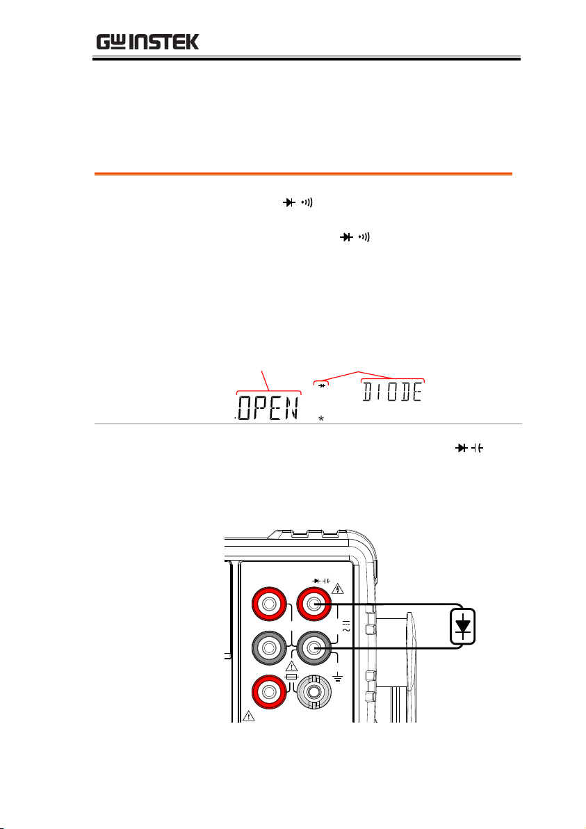
2. The mode will switch to Diode mode
immediately, as shown below.
Display
Diode
state
Diode function
indicator
CVCCSWEEPFILTRCLSTOCOMP2ND
SHIFTERRLIMITAUTOMATH4W2WDCAC
mdB
%
AVmm
HzWkM
WSFC
RMTMAXMINRELHOLDSMFAUTO4W2WDC
Connection
Connect the test lead between the VΩ
terminal and COM terminal; Anode-V,
Cathode-COM. The display updates the
reading.
1000V
750V
500Vpk
INPUT
FUSE
V
W
SENSE
W
4W
COM
200Vpk
H I
LO
10A 1A
CAT II 600V
Diode Test
The diode test checks the forward bias characteristics of a diode by
running a constant forward bias current of approximately 1mA
through the DUT.
45
Page 46
GDM-8351 User Manual
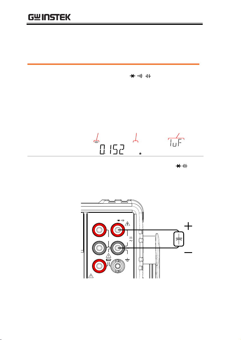
Set to
Capacitance
Measurement
1. Press the SHIFT →
/
( ) keys to activate
capacitance measurement.
2. The mode will switch to capacitance mode
immediately, as shown below.
Display
REARGPIBCVCCSWEEPFILTRCLSTOCOMP2ND
dBmEXTSHIFTERRLIMITAUTOMATH4W2WDCAC
AVmm
HzWkM
WSFC
mdB
%
AVmm
HzWkM
WSFC
RMTMAXMINRELHOLDSMFAUTO4W2WDCAC
μF
Capacitance
indicator
Capacitance
units
Measurement
range
Connection
Connect the test lead between the VΩ
terminal and COM terminal; Positive-V,
Negative-COM. The display updates the
reading.
1000V
750V
500Vpk
INPUT
FUSE
V
W
SENSE
W
4W
COM
200Vpk
H I
LO
10A 1A
CAT II 600V
Capacitance Measurement
The capacitance measurement function checks the capacitance of a
component.
46
Page 47
OPERATION
Auto Range
To turn the automatic range selection On/Off,
press the AUTO key.
Manual Range
Press the Up or the Down key to select the
range. The AUTO indicator turns Off
automatically. If the appropriate range is
unknown, select the highest range.
Selectable
Capacitance
Ranges
Range
Resolution
Full scale
10nF
10pF
12nF
100nF
100pF
120nF
1μF
1nF
1.2μF
10μF
10nF
12μF
100μF
100nF
120μF
Note
For further details, please see the specifications on
page 149.
Note
The refresh rate settings and the EXT trigger
cannot be used in the capacitance mode.
Select the Capacitance Range
The capacitance range can be set automatically or manually.
47
Page 48
GDM-8351 User Manual
Procedure
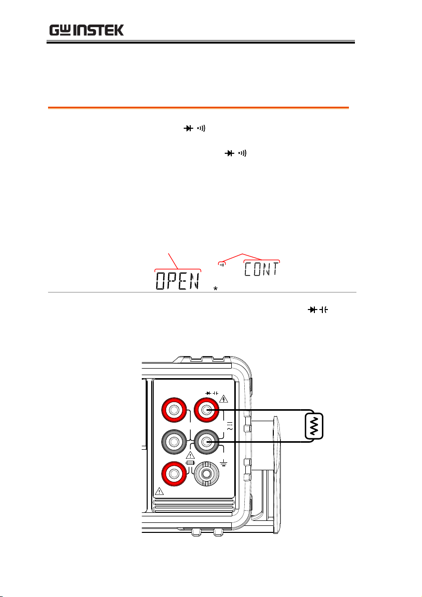
1. Press the
/
key twice to activate continuity
testing.
Note: pressing the
/
key once will activate
diode testing.
2. The mode will switch to continuity testing
immediately, as shown below.
Display
W
S
Continuity
state
Continuity function
indicator
Connection
Connect the test lead between the VΩ
terminal and COM terminal. The display
updates the reading.
1000V
750V
500Vpk
INPUT
FUSE
1.25A/1000V
V
W
SENSE
W
4W
COM
200Vpk
H I
LO
10A 1A
CAT II 600V
Continuity Test
The continuity test checks that the resistance in the DUT is low
enough to be considered continuous (of a conductive nature).
48
Page 49

OPERATION
Range
Threshold
0 to 1000Ω (Default Threshold:10Ω)
Resolution
1Ω
Procedure
1. Press MENU.
2. Go to the MEAS menu on level 1
3. Go to the CONT menu on level 2
4. Set the continuity threshold level in ohms.
5. Press the Enter key to confirm the continuity
settings.
6. Press EXIT to exit the CONT setting menu.
Display
W
Continuity
setting
Continuity function
indicator
Set Continuity Threshold
The continuity threshold defines the maximum resistance allowed
in the DUT when testing the continuity.
49
Page 50
GDM-8351 User Manual
Range
PASS
Beeps when the continuity passes.
FAIL
Beeps when the continuity fails.
OFF
Beeper is turned off.
Procedure
1. Press MENU.
2. Go to the SYSTEM menu on level 1
3. Go to the BEEP menu on level 2
4. Set the BEEP setting to PASS, FAIL or OFF.
5. Press the Enter key to confirm the beeper
settings.
6. Press EXIT to exit the BEEP setting menu.
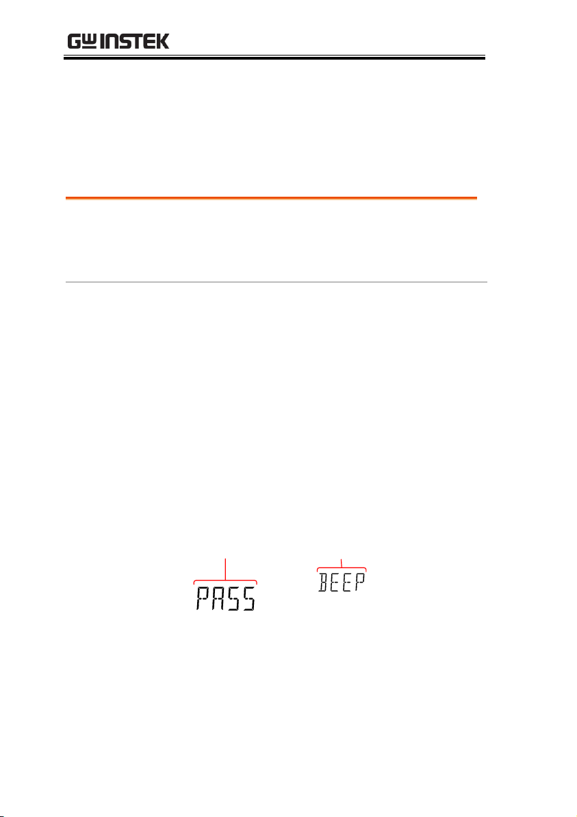
Display
Beep
setting
Beep menu
indicator
Continuity Beeper Settings
The beeper setting defines how the GDM-8351 notifies the
continuity test result to the user.
Note: When the Beeper setting is off it will also turn off the keypad
tones as well as any error or warning tones.
50
Page 51
OPERATION
Range
Frequency
10Hz~1MHz
Period
1.0μs ~100ms
Procedure
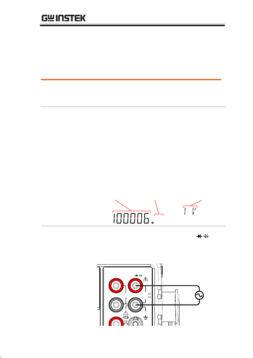
To measure frequency, press the Hz/P key
once. The frequency will be displayed on the
primary screen and the range will be displayed
on the secondary display.
To measure the period, press the Hz/P key
twice. The period will be displayed on the
primary screen and the range will be displayed
on the secondary display.
Display
REARGPIBCVCCSWEEPFILTRCLSTOCOMP2ND
dBmEXTSHIFTERRLIMITAUTOMATH4W2WDCAC
AVmm
HzWkM
WSFC
mdB
%
AVmm
HzWkM
WSFC
RMTMAXMINRELHOLDSMFAUTO4W2WDCAC
nμF
Measurement
Frequency or
period units
Voltage/Current
range setting
Connection
Connect the test lead between the VΩ
terminal and the COM terminal. The display
updates the reading.
1000V
750V
500Vpk
INPUT
V
W
SENSE
W
4W
COM
200Vpk
H I
LO
Frequency/Period Measurement
The GDM-8351 can be used to measure the frequency or period of a
signal. This function can measure either the voltage
frequency/period or current frequency/period, depending on
which jack the input signal is input from.
51
Page 52
GDM-8351 User Manual
Range
Voltage
100mV, 1V, 10V, 100V, 750V
Current
10mA, 100mA, 1A, 10A
Note
The input jack setting determines whether the
voltage frequency/period or current
frequency/period is being measured. See page 80
for details.
Manual Range
Set the range with the Up and Down keys. The
AUTO indicator will turn off when a new range
is selected.
Autorange
1. Press the Auto/Enter key.
2. AUTO will be displayed on the screen again.
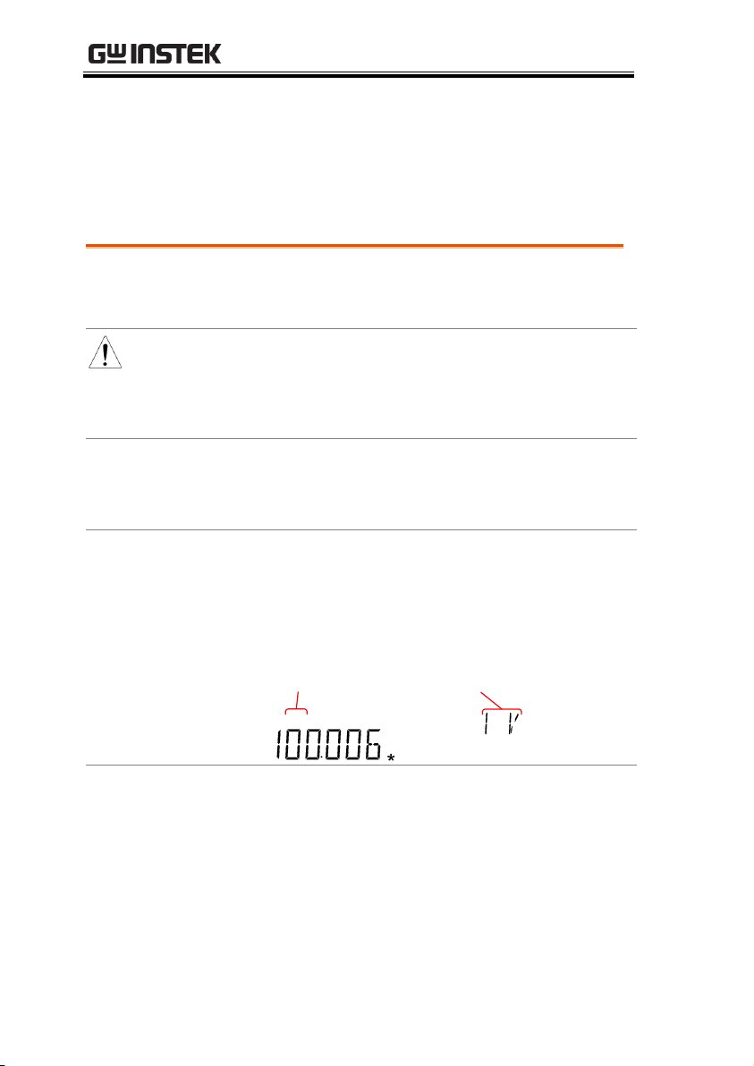
Display
REARGPIBCVCCSWEEPFILTRCLSTOCOMP2ND
dBmEXTSHIFTERRLIMITAUTOMATH4W2WDCAC
Vmm
HzWkM
SFC
mdB
%
AVmm
HzWkM
WSFC
RMTMAXMINRELHOLDSMFAUTO4W2WDCAC
nμF
Autorange
indicator
Voltage/Current
range setting
Note
Pressing the 2nd key twice will toggle the view of
the second display between the voltage/current
range and the menu function (FREQ or PERIOD).
Note that the voltage/current range can actually
still be set even when the secondary display has
been toggled to show the menu function.
Frequency/Period Settings
The input voltage/current range for frequency/period
measurements can be set to Auto range or to Manual. By default,
the voltage/current range is set to Auto for both the period and
frequency.
52
Page 53
OPERATION
Temperature
Range & Type
Thermocouple:
-200°C ~ +300°C
Type:
J, K, T
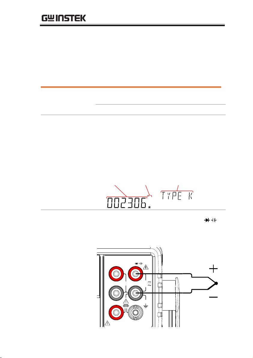
Procedure
To make temperature measurements, press
SHIFT → 2W/4W (TEMP).
The temperature mode appears showing the
temperature on the primary display and the
type of sensor on the secondary display.
Display
GPIBCVCCSWEEPFILTRCLSTOCOMP2ND
EXTSHIFTERRLIMITAUTOMATH4W2WDCAC
mm
kM
FC
mdB
%
AVmm
HzWkM
WSFC
RMTMAXMINRELHOLDSMFAUTO4W2WDCAC
nμF
Measurement
Temp.
units
Sensor type
Connection
Connect the sensor lead between the VΩ
terminal and the COM terminal. The display
updates the reading.
1000V
750V
500Vpk
INPUT
FUSE
1.25A/1000V
V
W
SENSE
W
4W
COM
200Vpk
H I
LO
10A 1A
CAT II 600V
Temperature Measurement
The GDM-8351 can measure temperature using a thermocouple. To
measure temperature, the DMM accepts a thermocouple input and
calculates the temperature from the voltage fluctuation. The
thermocouple type and reference junction temperature are also
considered.
53
Page 54

GDM-8351 User Manual
Range
Units
˚C, ˚F
Procedure
1. Press the MENU key.
2. Go to TEMP on level 1.
3. Go to UNIT on level 2.
4. Select either C (Celsius) or F (Farenheit).
5. Press the Enter key to confirm.
6. Press the EXIT key to exit from the temperature
menu.
Display
Temperature
unit setting
Unit menu
indicator
Set the Temperature Units
54
Page 55
OPERATION
Thermocouple
type and range
Type
Measurement Range
Resolution
J -200 to +300˚C
0.01 °C
K -200 to +300˚C
0.01 °C
T -200 to +300˚C
0.01 °C
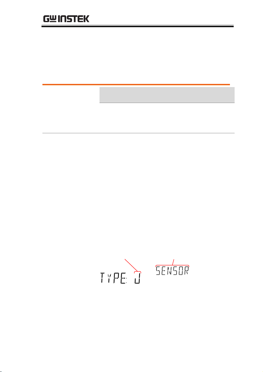
Procedure
1. Press the MENU key.
2. Go to TEMP on level 1.
3. Go to SENSOR on level 2.
4. Select the thermocouple type (J, K, T).
5. Press the Enter key to confirm.
6. Press the EXIT key to exit from the temperature
menu.
Display
Thermocouple
type setting
Sensor menu
indicator
Select Thermocouple Type
The GDM-8351 accepts thermocouple inputs and calculates the
temperature from the voltage difference of two dissimilar metals.
Thermocouple type and reference junction temperature are also
considered.
55
Page 56
GDM-8351 User Manual
Range
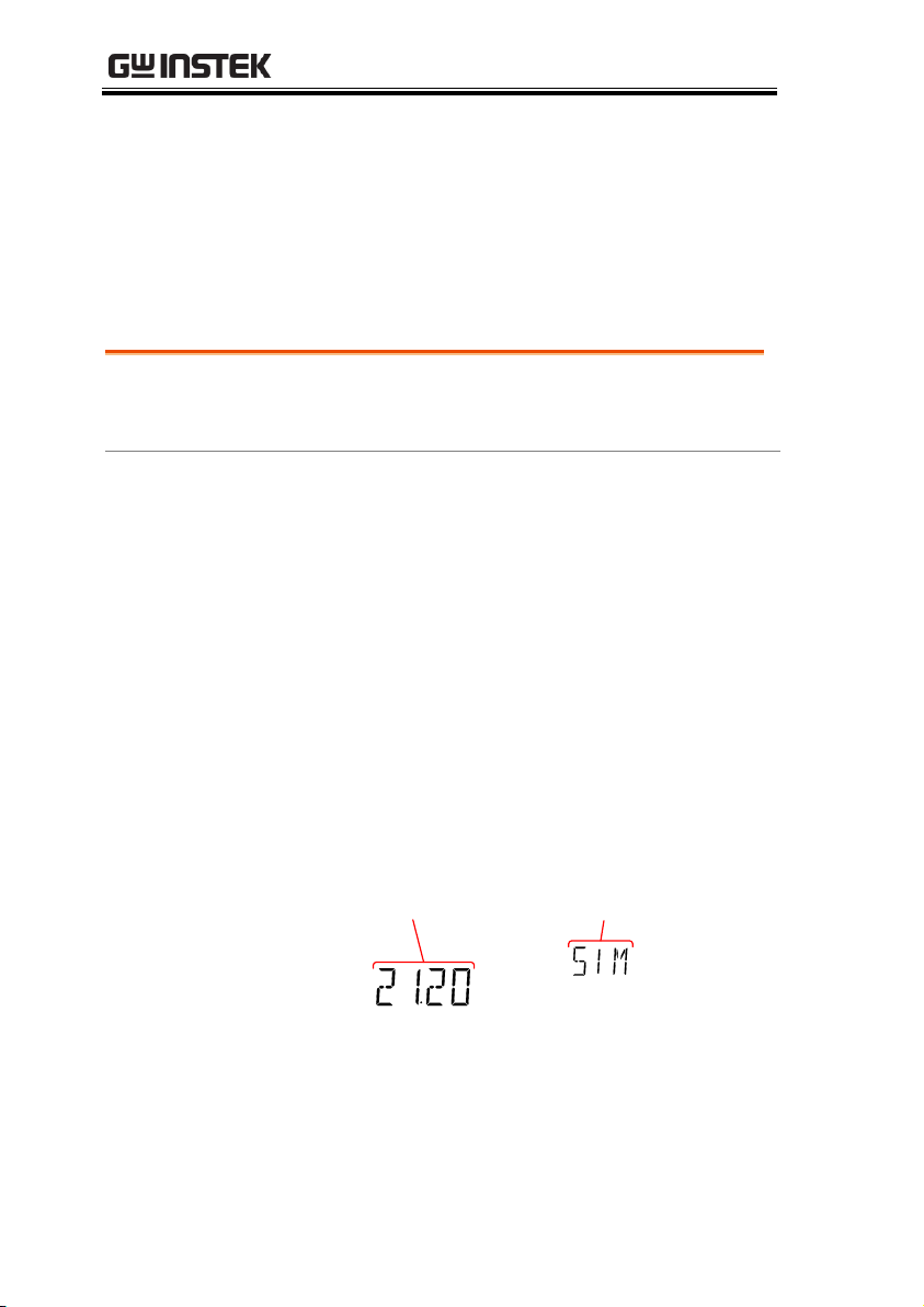
SIM
0 ~ 50˚C (default: 23.00˚C)
Resolution
0.01˚C
Procedure
1. Press the MENU key.
2. Go to TEMP on level 1.
3. Go to SIM on level 2.
4. Set the SIM (simulated) reference junction
temperature.
5. Press the Enter key to confirm.
6. Press the EXIT key to exit from the temperature
menu.
Display
Reference junction
temperature setting
SIM menu
indicator
Set the Reference Junction Temperature
When a thermocouple is connected to the DMM, the temperature
difference between the thermocouple lead and the DMM input
terminal should be taken into account and be cancelled out;
otherwise an erroneous temperature might be added. The value of
the reference junction temperature should be determined by the
user.
56
Page 57

OPERATION
Supported Dual
Measurement
modes
Primary
Display
Secondary Display
ACV
DCV
ACI
DCI
Hz/P
Ω
ACV
● ● ● ● ●
X
DCV
● ● ●
●
X X ACI
● ● ● ● ●
X
DCI
● ● ●
●
X
X
Hz/P ● X ● X ● X Ω X X X X X
●
Dual Measurement Overview
The dual measurement mode allows you to use the 2nd display to
show another item, thus allowing you to view two different
measurement results on the screen.
When the multimeter is used in dual measurement mode, both
displays are updated from either a single measurement or from two
separate measurements. If the primary and secondary
measurement modes have the same range, rate and rely on the
same fundamental measurement, then a single measurement is
taken for both displays; such as ACV and frequency/period
measurements. If the primary and secondary displays use different
measurement functions, ranges or rates, then separate
measurements will be taken for each display. For example, ACV
and DCV measurements.
Most of the basic measurement functions, except for
resistance/continuity can be used in the dual measurement mode.
Supported Dual Measurement Modes
The following table lists all the measurement functions that are
supported with the dual measurement function.
57
Page 58
GDM-8351 User Manual
Procedure
1. Choose one of the basic measurement functions
from the table above to set the measurement
mode for the primary display.
For example, press DCV to set the first display
to DCV measurement.
2. To set a measurement mode for the second
display, press the 2ND key and then select the
second measurement mode.
For example, press 2ND, SHIFT, ACV(ACI) to
select ACI measurement for the second display.
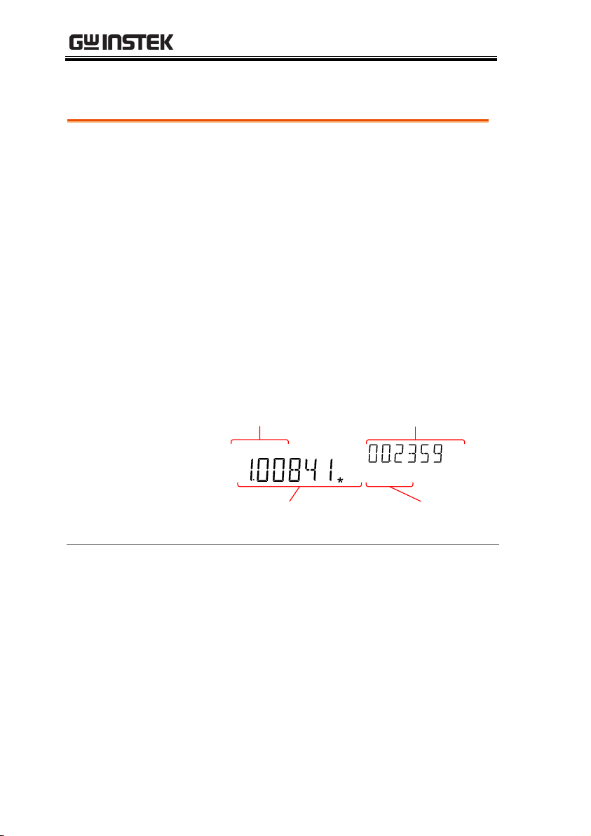
Display
Indicators for 1st
measurement
2nd measurement
and unit
Indicators for 2nd
measurement
1st measurement
and unit
REARGPIBCVCCSWEEPFILTRCLSTOCOMP2ND
dBmEXTSHIFTERRLIMITAUTOMATH4W2WDCAC
AVmm
HzWkM
WSFC
mdB
%
AVmm
HzWkM
WSFC
RMTMAXMINRELHOLDSMFAUTO4W2WDCAC
nμF
Using Dual Measurement Mode
58
Page 59
OPERATION
Editing the
Measurement
Parameters
After the secondary measurement function has
been activated, the rate, range and
measurement item can be edited for either the
primary or secondary display. Note however, it
is more practical to configure the first or second
measurement items before activating dual
measurement mode.
To edit measurement parameters in dual
measurement mode, you must first set which
display is the active display. The 2ND icon
under the secondary display determines which
display is the active display.
Procedure
1. Toggle whether the primary or secondary
display is the active display by pressing the
2ND key:
Primary display is the active display: 2ND is not
visible on the display.
Secondary display is the active display: 2ND is
visible on the display.
Note
Do not hold the 2ND key. This will turn the dual
measurement mode off.
2. Edit the range, rate or measurement item for
the active display in the same way as for single
measurement operation. See the Basic
Measurement chapter for details (page 30).
Turn Off 2nd
Measurement
To turn Off the second measurement, press and
hold the 2ND key for more than 1 second.
59
Page 60
GDM-8351 User Manual
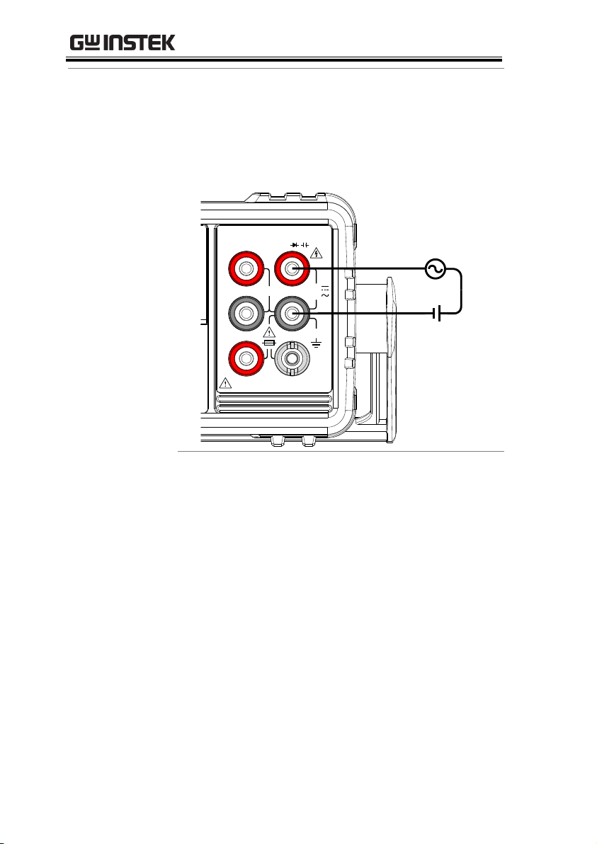
Connection
The diagrams below describe how to connect
the DMM to measure a number of common
dual measurement items.
Voltage and Frequency/Period measurement
1000V
750V
500Vpk
INPUT
FUSE
1.25A/1000V
V
W
SENSE
W
4W
COM
200Vpk
H I
LO
10A 1A
CAT II 600V
60
Page 61
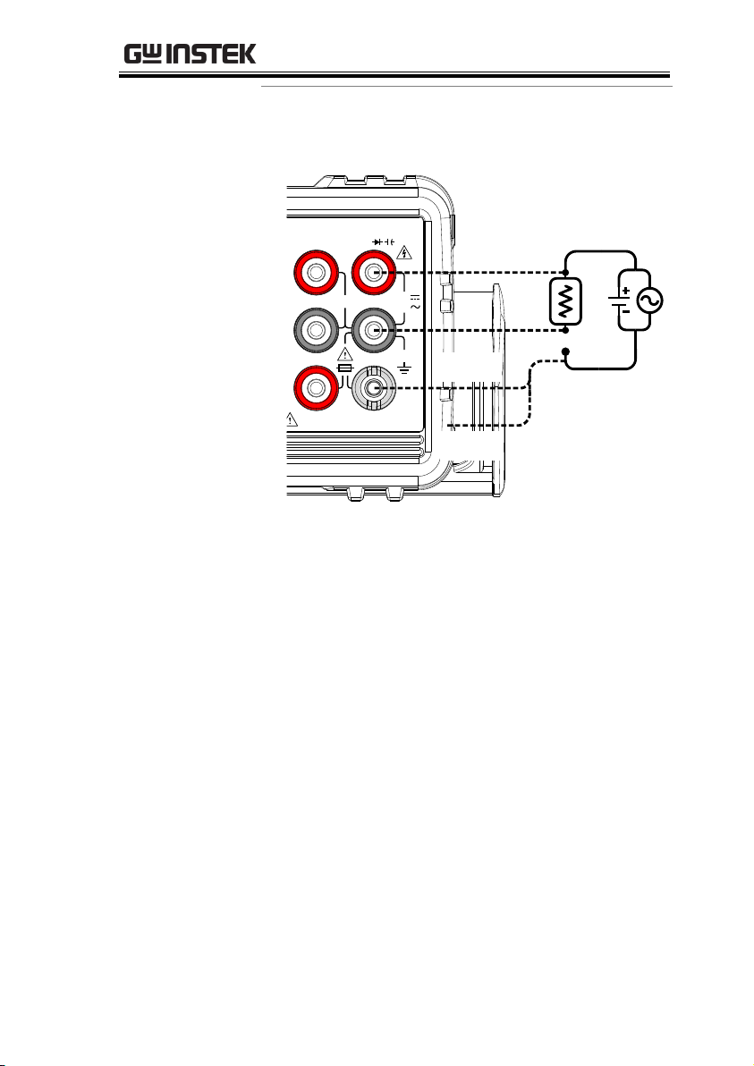
Voltage/Frequency/Period and Current
Measurement
1000V
750V
500Vpk
INPUT
FUSE
1.25A/1000V
V
W
SENSE
W
4W
COM
200Vpk
CAT II 600V
Load
0~1A
0~10A
Note: DC Current measurements will be displayed
as a negative value as the polarity of the current
leads has been reversed.
Please take into account the resistance of the test
leads and internal resistance of the current
connection as it is in series with the test circuit.
The above measuring configuration is used to
measure the voltage present on the resistance
under test and the current through the resistance
under test when using the DCI/DCV or ACI/ACV
dual measurement function.
OPERATION
61
Page 62
GDM-8351 User Manual
Advanced
Meas.
Basic Measurement
ACV/
DCV
ACI/
DCI
Ω
Hz/P
TEMP
DIODE
CAP
dB ● X X X X X
X
dBm ● X X X X X
X
Max/Min
● ● ● ● ●
X
●
Relative
● ● ● ● ●
X
●
Hold
● ● ● ● ●
X
X
Compare
● ● ● ● ●
X
●
Math
● ● ● ● ●
X
X
Advanced Measurement Overview
Advanced measurement mainly refers to the type of measurement
which uses the result obtained by one of the basic measurements:
ACV, DCV, ACI, DCI, Resistance, Diode/Continuity,
Frequency/Period, and Temperature.
Supported Advanced Measurement Functions
The following table lists all the advanced measurement functions
and which of the basic measurement functions that they support.
62
Page 63

OPERATION
Overview
Using the ACV or DCV measurement results,
the DMM calculates the dB or dBm value based
on a reference resistance value in the following
way:
dBm= 10 x log10 (1000 x Vreading2 / Rref)
dB= dBm – dBmref
W= Vreading2/Rref
Where:
Vreading= Input Voltage, ACV or DCV;
Rref= Reference resistance simulating an output
load;
dBmref= Reference dBm value
Procedure
1. Select ACV or DCV measurement. See page 32.
2. To measure dBm, press SHIFT →
MENU(dBm)
The primary display will show the dBm
measurement while the secondary display
shows the reference resistance.
dBm/dB/W Measurement
dBm/dB Calculation
Measuring dBm/W
63
Page 64
GDM-8351 User Manual
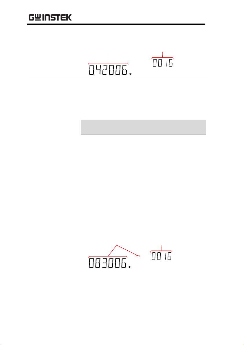
Display
dBm
measurement
Reference
resistance
REARGPIBCVCCSWEEPFILTRCLSTOCOMP2ND
dBmEXTSHIFTERRLIMITAUTOMATH4W2WDCAC
Vmm
HzWkM
SFC
mdB
%
AVmm
HzWkM
WSFC
RMTMAXMINRELHOLDSMFAUTO4W2WDCAC
nμF
Setting the
Reference
Resistance
To set the reference resistance, use the Up and
Down arrow keys.
The selectable reference resistances are shown
below.
Selectable reference resistances
2 4 8 16
50
75
93
110
124
125
135
150
250
300
500
600
800
900
1000
1200
8000
View the result in
Watts
When the reference resistance is less than 50Ω,
it is possible to calculate the power (in watts). If
the reference resistance is equal to or greater
than 50Ω, then this step can be ignored.
Press SHIFT →
MENU(dBm)
again to view the
result in watts.
Display
REARGPIBCVCCSWEEPFILTRCLSTOCOMP2ND
dBmEXTSHIFTERRLIMITAUTOMATH4W2WDCAC
AVmm
HzWkM
WSFC
mdB
%
AVmm
HzWkM
WSFC
RMTMAXMINRELHOLDSMFAUTO4W2WDCAC
nμF
Power measurement
and unit
Reference
resistance
Exit dBm
Measurement
Press SHIFT →
MENU(dBm)
again to exit the
dBm measurement, or simply activate another
measurement function.
64
Page 65
OPERATION
Procedure
1. Select ACV or DCV measurement. See page 32.
2. Press the SHIFT → Hz/P(dB) keys to activate
the dB measurement mode.
The 1st display shows the dB reading, the
second display shows the voltage reading.
Display
REARGPIBCVCCSWEEPFILTRCLSTOCOMP2ND
dBmEXTSHIFTERRLIMITAUTOMATH4W2WDCAC
AVmm
HzWkM
WSFC
mdB
%
AVmm
HzWkM
WSFC
RMTMAXMINRELHOLDSMFAUTO4W2WDCAC
nμF
dB
measurement
Voltage
reading
View the dBm
Reference Value
To view the dBm reference value, press the
2ND key.
The Up and Down arrow keys can also be used
to change the voltage range or the reading.
Exit dB
Measurement
Press the SHIFT → Hz/P(dB) keys again to exit
the dB measurement, or simply activate another
measurement function.
Measure dB
dB is defined as [dBm−dBmref]. When the dB measurement is
activated, the DMM calculates the dBm using the reading at the
first moment and stores it as dBmref.
65
Page 66
GDM-8351 User Manual
Applicable
measurements
The Max/Min function can be used with the
following basic measurement functions:
ACV, DCV, ACI, DCI, Ω, Hz/P, TEMP,
Procedure
For Max measurement, press the MX/MN key
once.
For Min measurement, press the MX/MN key
twice.
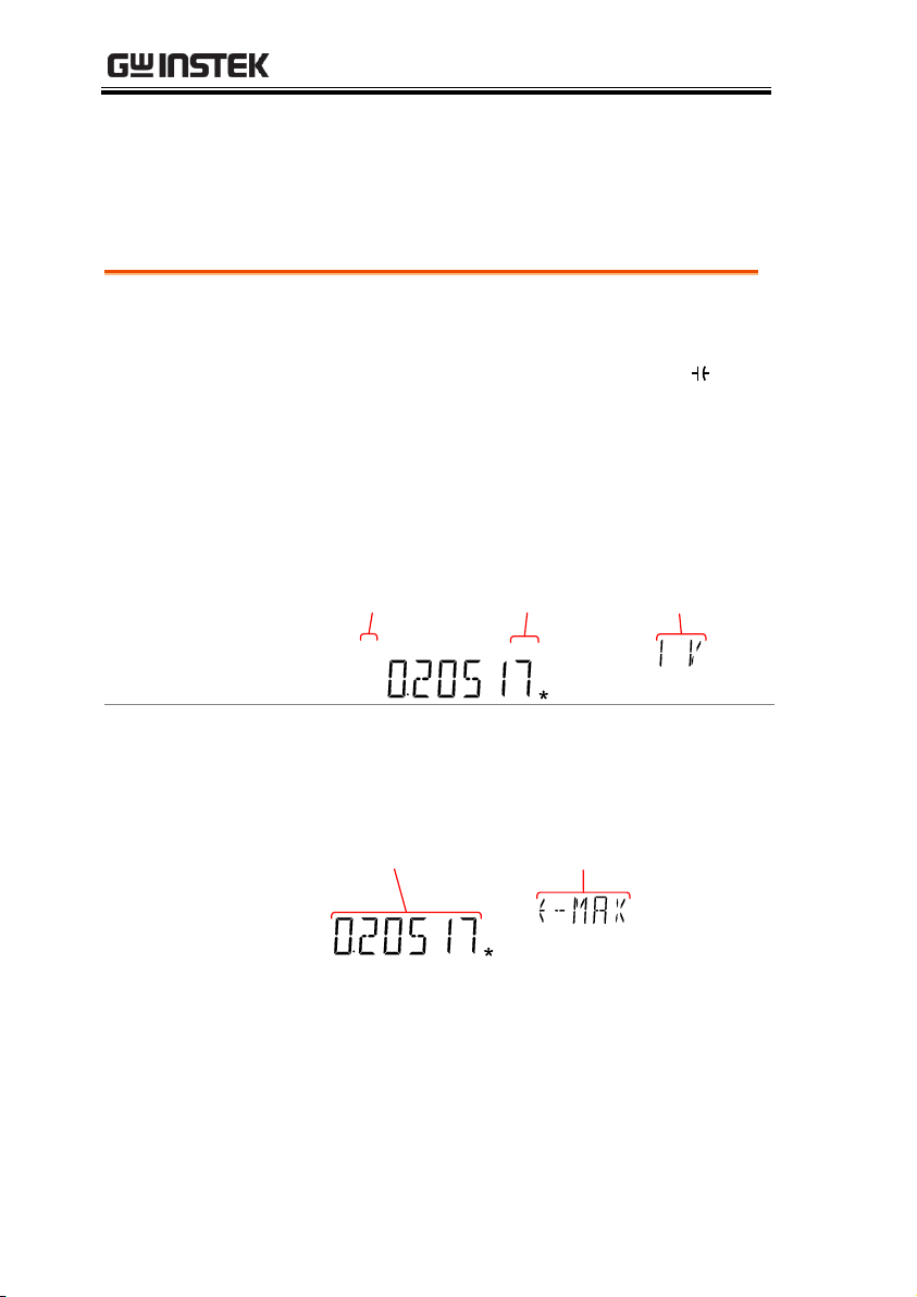
Display
REARGPIBCVCCSWEEPFILTRCLSTOCOMP2ND
dBmEXTSHIFTERRLIMITAUTOMATH4W2WDCAC
AVmm
HzWkM
WSFC
mdB
%
AVmm
HzWkM
WSFC
RMTMAXMINRELHOLDSMFAUTO4W2WDCAC
nμF
Basic meas.
function
Max/Min
indicator
Measurement
range
View Max/Min
Value
Press the 2ND key to view the Max or Min
value.
Display
CVCCSWEEPFILTRCLSTOCOMP2ND
SHIFTERRLIMITAUTOMATH4W2WDCAC
m
M
C
mdB
%
AVmm
HzWkM
WSFC
RMTMAXMINRELHOLDSMFAUTO4W2WDCAC
nμF
Max/Min
reading
Max/Min
mode
Deactivate
Max/Min
Measurement
Hold the MX/MN key for two seconds to
deactivate, or simply activate another
measurement function.
Max/Min Measurement
Maximum and Minimum measurement function stores the highest
(maximum) or lowest (minimum) reading and shows it on the first
display when the 2ND key is pressed.
66
Page 67
OPERATION
Applicable
measurements
The relative function can be used with the
following basic measurement functions:
ACV, DCV, ACI, DCI, Ω, Hz/P, TEMP,
Procedure
Press the REL key. The measurement reading at
that instant becomes the reference value.
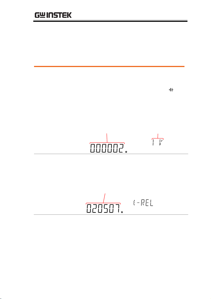
Display
REARGPIBCVCCSWEEPFILTRCLSTOCOMP2ND
dBmEXTSHIFTERRLIMITAUTOMATH4W2WDCAC
AVmm
HzWkM
WSFC
mdB
%
AVmm
HzWkM
WSFC
RMTMAXMINRELHOLDSMFAUTO4W2WDCAC
nμF
Relative
value
Range
View Relative
Reference Value
Press the 2ND key to view the relative reference
value at full scale.
Display
REARGPIBCVCCSWEEPFILTRCLSTOCOMP2ND
dBmEXTSHIFTERRLIMITAUTOMATH4W2WDCAC
AVmm
HzWkM
WSFC
mdB
%
AVmm
HzWkM
WSFC
RMTMAXMINRELHOLDSMFAUTO4W2WDCAC
nμF
Relative
reference value
Relative Measurement
Relative measurement stores a value, typically the data at that
instant, as the reference. The measurement following the reference
is displayed as the delta between the reference. The reference value
will be cleared upon exiting.
67
Page 68
GDM-8351 User Manual
Manually Set the
Relative
Reference Value
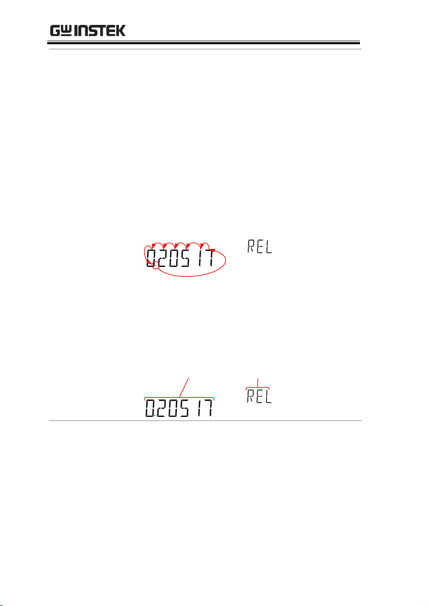
1. To manually set the relative reference value,
press SHIFT → REL(REL#).
The REL value is displayed on the screen at full
scale.
2. Use the Left and Right arrow keys to navigate
to the digit to be edited or to select the decimal
point.
Use the Up and Down arrow keys to edit the
selected digit or to place the position of the
decimal point.
REARGPIBCVCCSWEEPFILTRCLSTOCOMP2ND
dBmEXTSHIFTERRLIMITAUTOMATH4W2WDCAC
AVmm
HzWkM
WSFC
mdB
%
AVmm
HzWkM
WSFC
RMTMAXMINRELHOLDSMFAUTO4W2WDCAC
nμF
3. Press the Enter key to confirm, alternatively
press Exit to cancel setting the relative reference
value.
Display
Relative
value setting
REL setting
mode
REARGPIBCVCCSWEEPFILTRCLSTOCOMP2ND
dBmEXTSHIFTERRLIMITAUTOMATH4W2WDCAC
AVmm
HzWkM
WSFC
mdB
%
AVmm
HzWkM
WSFC
RMTMAXMINRELHOLDSMFAUTO4W2WDCAC
nμF
Deactivate
Relative
Measurement
Press the REL key again to deactivate the
Relative measurement mode, or simply activate
another measurement function.
68
Page 69
OPERATION
Applicable
measurements
The hold function can be used with the
following basic measurement functions:
ACV, DCV, ACI, DCI, Ω, Hz/P, TEMP
Procedure
1. Press the HOLD key.
2. The measurement reading appears on the
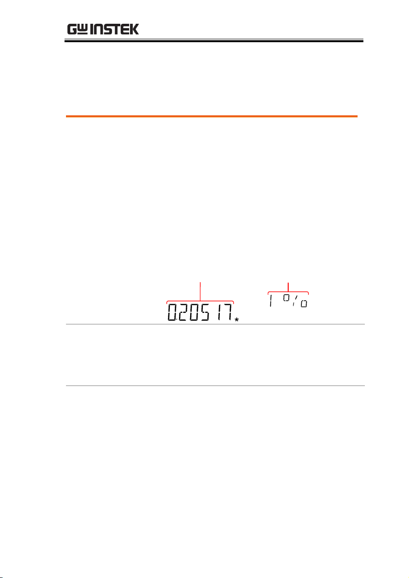
primary display and the hold threshold on the
secondary display.
Display
REARGPIBCVCCSWEEPFILTRCLSTOCOMP2ND
dBmEXTSHIFTERRLIMITAUTOMATH4W2WDCAC
Vmm
WkM
SFC
mdB
%
AVmm
HzWkM
WSFC
RMTMAXMINRELHOLDSMFAUTO4W2WDCAC
nμF
Measurement
reading
Hold
threshold
Set the Hold
Threshold
Use the Up and Down arrow keys to select a
hold threshold level, as a percentage.
Range
0.01%, 0.1%, 1%, 10%
Deactivate Hold
Measurement
Press the HOLD key for 2 seconds to deactivate
the hold measurement, or simply activate
another measurement function.
Hold Measurement
The Hold Measurement function retains the current measurement
data and updates it only when it exceeds the set threshold (as a
percentage of the retained value).
69
Page 70
GDM-8351 User Manual
Applicable
measurements
The compare function can be used with the
following basic measurement functions:
ACV, DCV, ACI, DCI, Ω, Hz/P, TEMP,
Procedure
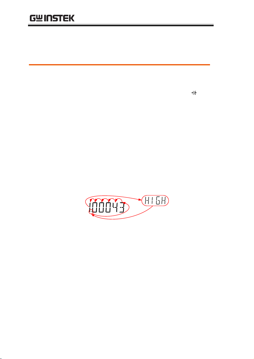
1. Press SHIFT → HOLD(COMP).
2. The high limit setting appears.
Use the Left and Right arrow keys to navigate
to the digit to be edited, or to select the decimal
point.
Use the Up and Down arrow keys to edit the
selected digit, or to place the position of the
decimal point.
V
3. Press the Enter key to save the high limit setting
and automatically go on to the low limit setting.
4. Enter the low limit setting in the same fashion
as the high setting.
5. Press the Enter key to confirm the low limit
settings.
6. The compare measurement results will appear
immediately:
If the current measurement reading is between
Compare Measurement
Compare measurement checks to see if the measurement data stays
between a specified upper (high) and lower (low) limit.
70
Page 71
OPERATION
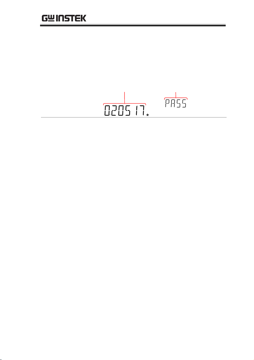
the high and low limits, PASS will be displayed
on the secondary display, If the reading is
below the low limit, LOW will be displayed. If
the reading is above the high limit, HIGH will
be displayed.
Display
GPIBCVCCSWEEPFILTRCLSTOCOMP2ND
EXTSHIFTERRLIMITAUTOMATH4W2WDCAC
m
M
C
mdB
%
AVmm
HzWkM
WSFC
RMTMAXMINRELHOLDSMFAUTO4W2WDCAC
nμF
Measurement
reading
Compare
result
Deactivate
Compare
Measurement
Press SHIFT → HOLD(COMP) to deactivate
compare measurements, or simply activate
another measurement function.
71
Page 72

GDM-8351 User Manual
Applicable
Measurements
The math function can be used with the
following basic measurement functions:
ACV, DCV, ACI, DCI, Ω, Hz/P, TEMP
Overview of Math
Functions
MX+B
Multiplies the reading (X) by the
factor (M) and adds/subtracts
offset (B).
1/X
Inverse. Divides 1 by the reading
(X).
Percentage
Runs the following equation:
100%
Reference
Reference)-(ReadingX
x
Procedure
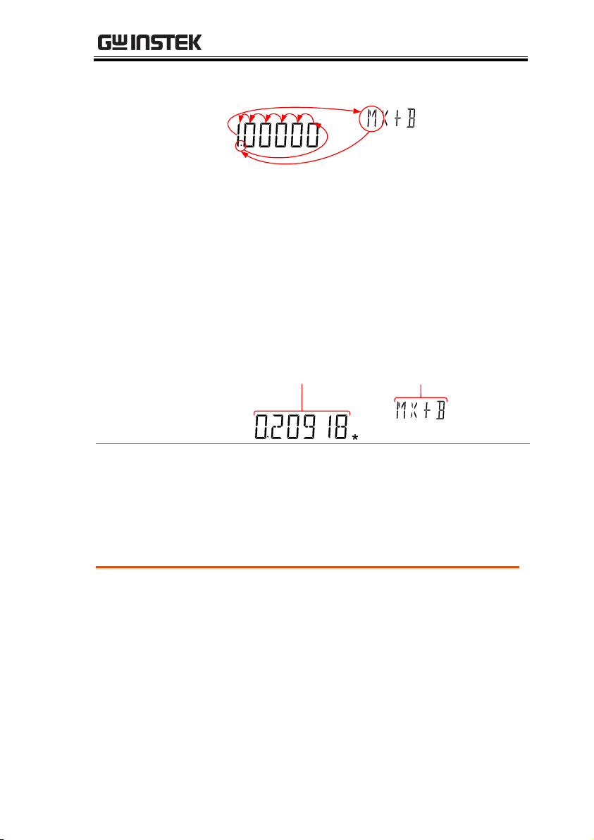
1. Press SHIFT → MX/MN(MATH) to enter the
MATH menu.
The MX+B setting appears. The M factor will be
flashing, indicating that the M factor is to be set.
2. Use the Left and Right arrow keys to navigate
to the digit to be edited or to select the decimal
point.
Use the Up and Down arrow keys to edit the
selected digit or to place the position of the
Math Measurement
Math Measurement Overview
Math measurement runs three types of mathematical operations,
MX+B, 1/X and Percentage based on the other measurement
results.
Measure MX+B
72
Page 73
OPERATION
decimal point.
3. Press Enter to confirm the M factor settings and
to automatically move onto the B offset setting.
4. Edit the B offset in the same fashion as the M
factor was edited.
5. Press Enter to confirm the B offset setting and
to begin the MX+B measurement.
Display
GPIBCVCCSWEEPFILTRCLSTOCOMP2ND
EXTSHIFTERRLIMITAUTOMATH4W2WDCAC
m
M
C
mdB
%
AVmm
HzWkM
WSFC
RMTMAXMINRELHOLDSMFAUTO4W2WDCAC
nμF
MX+B meausurement
reading
MX+B math
indicator
Deactivate Math
Measurement
Press SHIFT → MX/MN(MATH) to deactivate
the MATH function, or simply activate another
measurement function.
Procedure
1. Press SHIFT → MX/MN(MATH) to enter the
MATH menu.
The MX+B setting appears.
2. Press the Down key twice to skip past MX+B
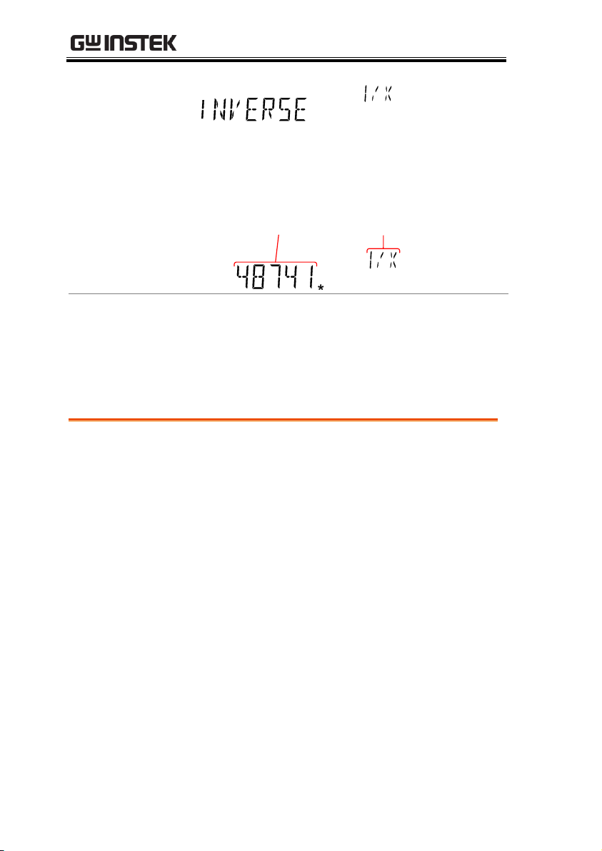
settings and go to the 1/X settings.
1/X will be flashing in the secondary display.
Measure 1/X
73
Page 74
GDM-8351 User Manual
3. Press Enter to activate the 1/X math function.
The results begin immediately.
Display
GPIBCVCCSWEEPFILTRCLSTOCOMP2ND
SHIFTERRLIMITAUTOMATH4W2WDCAC
m
M
C
mdB
%
AVmm
HzWkM
WSFC
RMTMAXMINRELHOLDSMFAUTO4W2WDCAC
nμF
1/X
measurement
1/X math
indicator
Deactivate Math
Measurement
Press the SHIFT → MX/MN(MATH) to
deactivate the MATH function, or simply
activate another measurement function.
Procedure
1. Press SHIFT → MX/MN to enter the MATH
menu.
2. The MX+B setting appears. Press the Up key to
skip past MX+B settings and go to the REF%
settings.
REF% will be flashing in the secondary display.
3. Use the Left and Right arrow keys to navigate
to the digit to be edited or to select the decimal
point.
Use the Up and Down arrow keys to edit the
selected digit or to place the position of the
decimal point.
Measure Percentage
74
Page 75
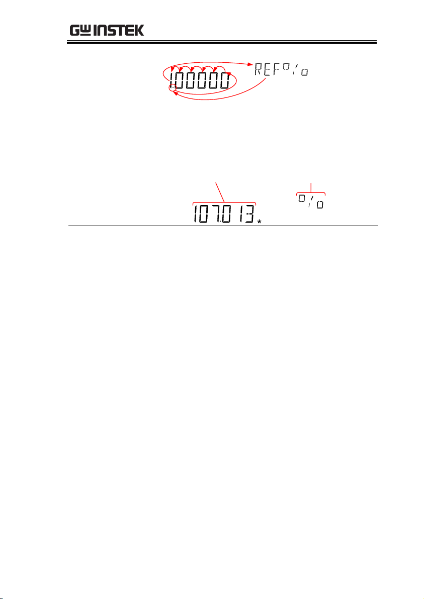
OPERATION
4. Press Enter to confirm the REF% setting and to
begin the Percentage measurement.
Display
SDCVAUTO
MATH
Calculated percentage
meausurement
% function
indicator
Deactivate Math
Measurement
Press SHIFT → MX/MN to deactivate the
MATH function, or simply activate another
measurement function.
75
Page 76

GDM-8351 User Manual
View Serial Number ......................................................... 77
View Version Number ...................................................... 77
Brightness Settings ......................................................... 78
Input Resistance Settings ................................................ 79
Frequency/Period Input Jack Settings .............................. 80
Digital Filter .................................................................... 81
Digital Filter Overview ............................................... 81
Digital Filter Type Settings......................................... 83
Restore Factory Default Settings ...................................... 85
Trigger ............................................................................ 86
Trigger Settings .......................................................... 86
External Trigger .......................................................... 87
SYSTEM/DISPLAY
CONFIGURATION
76
Page 77
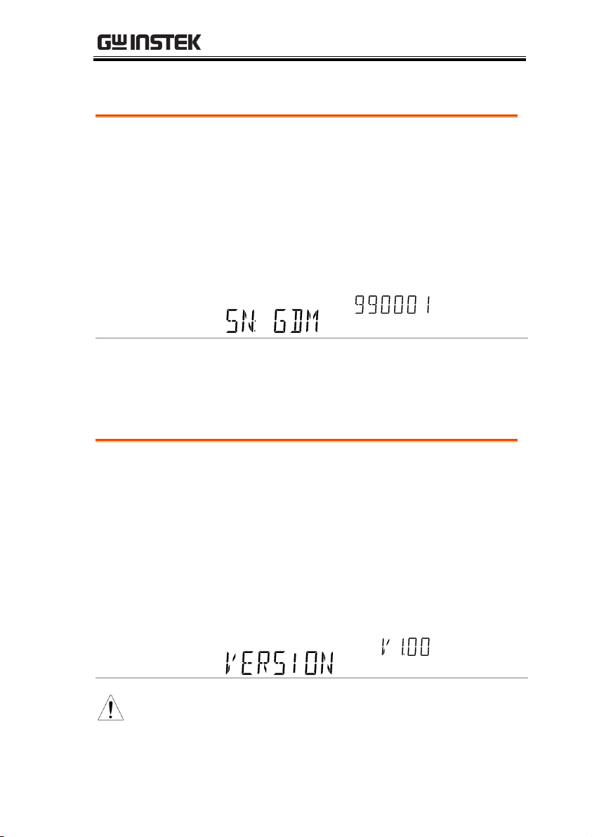
SYSTEM/DISPLAY CONFIGURATION
Procedure
1. Press the MENU key.
2. Go to SYSTEM on level 1.
3. Go to S/N on level 2.
4. The serial number will be displayed across both
the primary and secondary display.
Display
REARGPIBCVCCSWEEPFILTRCLSTOCOMP2ND
dBmEXTSHIFTERRLIMITAUTOMATH4W2WDCAC
AVmm
HzWkM
WSFC
mdB
%
AVmm
HzWkM
WSFC
RMTMAXMINRELHOLDSMFAUTO4W2WDCAC
nμF
Exit
Press the EXIT key twice to go back to the
measurement screen.
Procedure
1. Press the MENU key.
2. Go to FW on level 1.
3. Go to VER on level 2.
4. The firmware version number will be displayed
in the secondary display.
5. Press Exit to exit from the version menu.
Display
Note
For details about firmware updates, please contact
the GW Instek Service Center or visit the GW
Instek website at www.gwinstek.com.
View Serial Number
View Version Number
77
Page 78
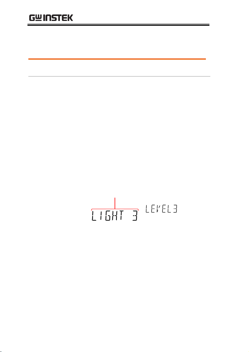
GDM-8351 User Manual
Range
Brightness
1 (dim) ~ 5 (bright)
Procedure
1. Press the MENU key.
2. Go to SYSTEM on level 1.
3. Go to LIGHT on level 2.
4. Set the light setting between 1 (dim) and 5
(bright).
5. Press the Enter key to confirm.
6. Press the EXIT key to exit from the brightness
settings.
Display
Brightness setting
Brightness Settings
The display has 5 settable brightness levels.
78
Page 79
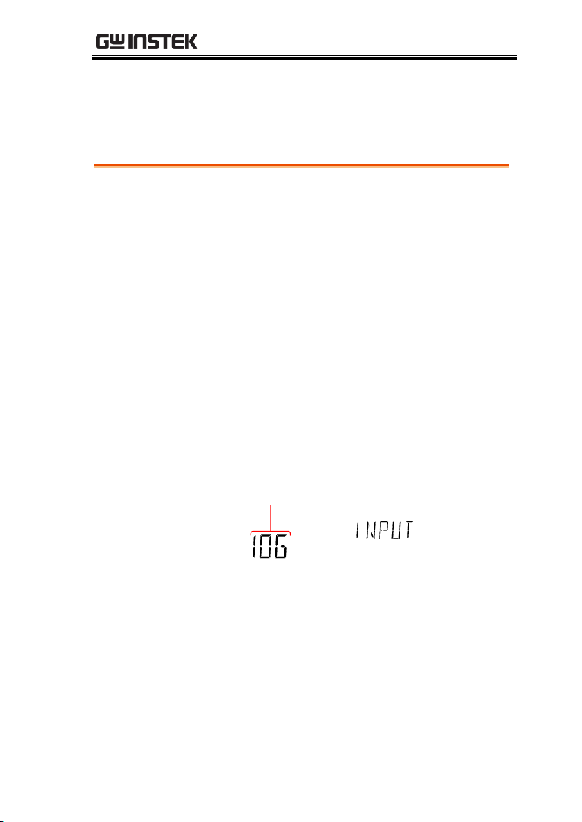
SYSTEM/DISPLAY CONFIGURATION
Range
Input resistance
10MΩ, 10GΩ
Default
10MΩ
Procedure
1. Press the MENU key.
2. Go to MEAS on level 1.
3. Go to INPUT R on level 2.
4. Set the input resistance to 10MΩ or 10GΩ
5. Press the Enter key to confirm.
6. Press the EXIT key to exit from the input
resistance menu.
Display
Input resistance
setting
Input Resistance Settings
The 100mV and 1V DC voltage ranges can be set to an input
resistance of 10MΩ or 10GΩ. This setting is only applicable for DC
voltage.
79
Page 80

GDM-8351 User Manual
Range
Injack
VOLT, 1A, 10A
Default
VOLT
Procedure
1. Press the MENU key.
2. Go to MEAS on level 1.
3. Go to INJACK on level 2.
4. Set the INJACK setting to either VOLT, 1A or
10A.
5. Press the Enter key to confirm.
6. Press the EXIT key to exit from the INJACK
menu.
Display
INJACK setting
Frequency/Period Input Jack Settings
The INJACK settings set which input terminal is used for frequency
or period measurements.
80
Page 81
SYSTEM/DISPLAY CONFIGURATION
Filter Basics
The digital filter converts the analog input signal
into digital format before passing it to the internal
circuits for processing. The filter affects the amount
of noise included in the measurement result.
Filter Type
The digital filter averages a specific number of
input signal samples to generate one reading. The
filter type defines the averaging method. The
following diagrams show the differences between
each filter type, using 4 samples per reading as an
example.
Moving Filter
The moving filter takes in one new sample and
discards the oldest sample per reading. This is the
default behavior when the digital filter is not
specified, and is recommended for most
applications.
Repeating Filter
The repeating filter renews all the samples per
reading.
1Sample #
1st reading Sample 1 - 4
2nd reading Sample 2 - 5
32 4 5 6 7 8 9 10 11 12
3rd reading Sample 3 - 6
1Sample #
1st reading
Sample 1 - 4
2nd reading
Sample 5 - 8
32 4 5 6 7 8 9 10 11 12
3rd reading
Sample 9 - 12
Digital Filter
Digital Filter Overview
81
Page 82
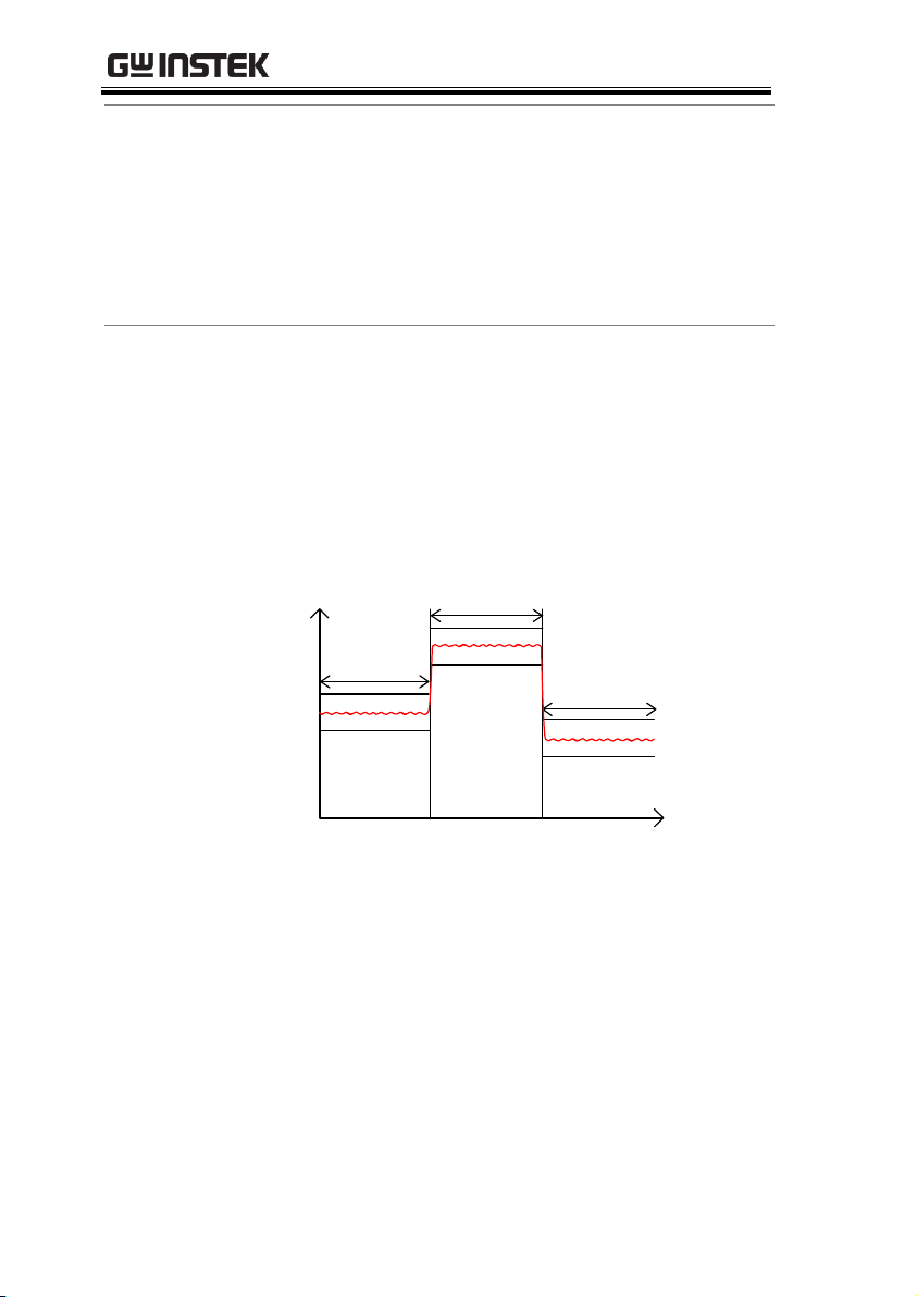
GDM-8351 User Manual
Filter Count
Filter count defines the number of samples to be
averaged per reading. More samples offer low
noise but a longer delay between measurements.
Less samples offer high noise but a shorter delay
between measurements.
Range:
2 ~ 320
Filter Window
The filter window defines the threshold for when
the digital filter data is updated again. When the
AD data falls in the range between TH and TL, the
filter keeps processing. When the AD data falls out
of the range between TH and TL, the filter will
restart. When measuring unstable signals,
appropriately setting the filter window can
improve the measurement speed.
Time
AD data
TH
TL
TH
TL
TH
TL
Filter
Filter
Filter
Restart
Restart
TH: Threshold High, TL: Threshold Low
Filter Window
Formula
Previous data*(1-window)< threshold< previous
data*(1+window).
Range:
10%, 1%, 0.1%, 0.01% and none
82
Page 83
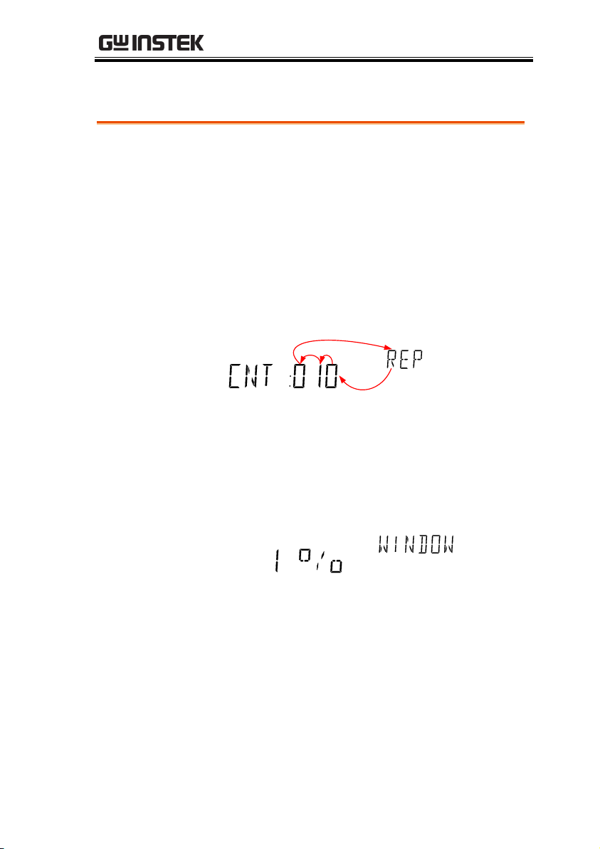
SYSTEM/DISPLAY CONFIGURATION
Procedure
1. Press SHIFT → FILTER(TYPE) to enter the
(Digital Filter) Type settings menu.
2. Use the Left and Right arrow keys to navigate
to the filter type setting or to select the digit to
be edited.
Use the Up and Down arrow keys to edit the
selected digit or to toggle the filter type
(REP<>MOV).
REARGPIBCVCCSWEEPFILTRCLSTOCOMP2ND
dBmEXTSHIFTERRLIMITAUTOMATH4W2WDCAC
AVmm
HzWkM
WSFC
mdB
%
AVmm
HzWkM
WSFC
RMTMAXMINRELHOLDSMFAUTO4W2WDCAC
nμF
3. Press Enter to confirm the filter type and the
CNT setting. The DMM will now automatically
go to the WINDOW setting.
4. Use the Up and Down arrow keys to set the
window threshold settings.
REARGPIBCVCCSWEEPFILTRCLSTOCOMP2ND
dBmEXTSHIFTERRLIMITAUTOMATH4W2WDCAC
AVmm
HzWkM
WSFC
mdB
%
AVmm
HzWkM
WSFC
RMTMAXMINRELHOLDSMFAUTO4W2WDCAC
nμF
5. Press Enter to confirm the settings.
6. Press EXIT to cancel.
Digital Filter Type Settings
83
Page 84
GDM-8351 User Manual
Display
REARGPIBCVCCSWEEPFILTRCLSTOCOMP2ND
dBmEXTSHIFTERRLIMITAUTOMATH4W2WDCAC
AVmm
HzWkM
WSFC
mdB
%
AVmm
HzWkM
WSFC
RMTMAXMINRELHOLDSMFAUTO4W2WDCAC
Filter indicator
Deactivate Digital
Filter
Press FILTER to deactivate the FILTER
function.
84
Page 85
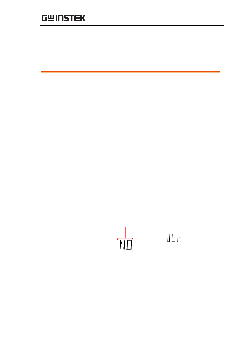
SYSTEM/DISPLAY CONFIGURATION
Range
Factory DEF
YES, NO
Procedure
1. Press the MENU key.
2. Go to SYSTEM on level 1.
3. Go to FACTORY on level 2.
4. Set the (FACTORY) DEF setting to YES or NO.
Choosing YES will restore the factory default
settings.
5. Press the Enter key to confirm and to restore
the factory default settings immediately.
“OK DEF” will be displayed when the default
settings are restored.
Display
Factory default setting
Restore Factory Default Settings
The factory default settings can be restored at anytime from the
System menu. Please see the Appendix on page 140 for a list of the
factory default settings.
85
Page 86
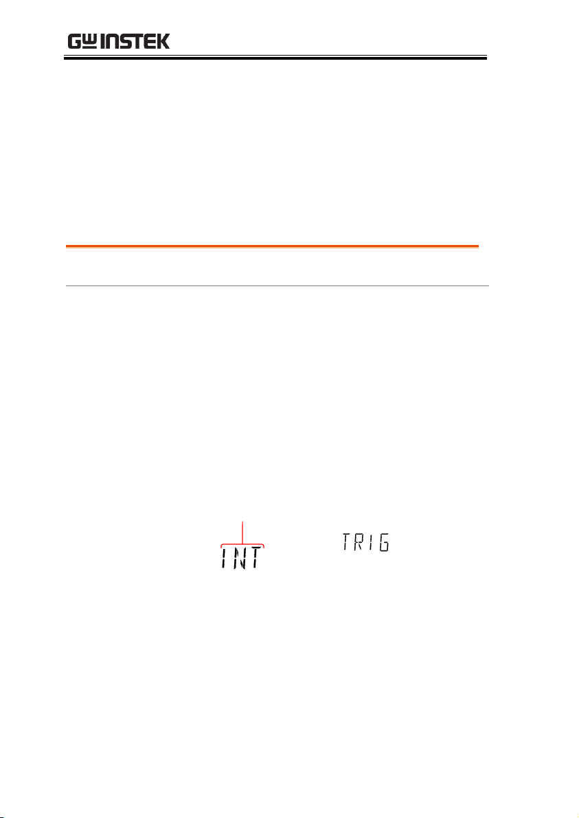
GDM-8351 User Manual
Range
Trigger
INT, EXT
Procedure
1. Press the MENU key.
2. Go to MEAS on level 1.
3. Go to TRIG on level 2.
4. Set the TRIG setting to either INT or EXT.
5. Press the Enter key to confirm.
6. Press the EXIT key to exit from the TRIG menu.
Display
GPIBCVCCSWEEPFILTRCLSTOCOMP2ND
SHIFTERRLIMITAUTOMATH4W2WDCAC
m
M
C
mdB
%
AVmm
HzWkM
WSFC
RMTMAXMINRELHOLDSMFAUTO4W2WDCAC
nμF
INJACK setting
Trigger
The measurements can be triggered internally or externally. When
set to internal, the DMM will be triggered automatically according
the refresh rate. When set to external, the DMM will wait for an
external trigger signal from the Digital I/O port or from the *TRG
command. See page 88 & 137 for more details.
Trigger Settings
86
Page 87
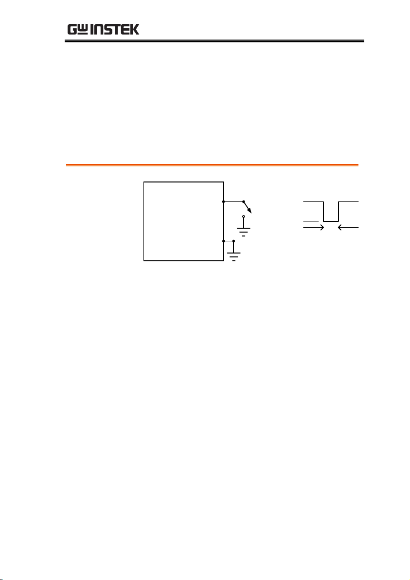
SYSTEM/DISPLAY CONFIGURATION
Digital I/O
Pin 5
Pin 6
Digital I/O Terminal
Trigger input
≥10μs
External Trigger
The external trigger uses the digital I/O pin for manual triggering
of the DMM. Pin 5 of the digital I/O port is normally high. To
trigger the DMM a low pulse of ≥10μs is needed.
The *TRG command can also be used to externally trigger the
DMM when the DMM is in the external trigger mode. See page 137
for details.
87
Page 88

GDM-8351 User Manual
Digital I/O Overview ....................................................... 89
Normal Mode ............................................................. 90
User Mode .................................................................. 91
DIGITAL I/O
88
Page 89
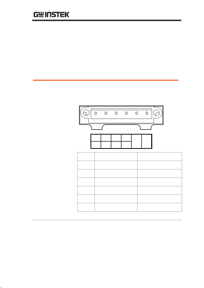
DIGITAL I/O
Pinout
DIGITAL I / O
H.F L.F PASS EOM
SET3SET2SET1 SET4
TRIG
IN
GND
Pin No.
Normal Mode
User Mode
1 High Fail
Set 1
2 Low Fail
Set 2
3 Pass
Set 3
4 EOM
Set 4
5 TRIG IN
TRIG IN
6 Ground
Ground
Digital I/O Overview
The Digital I/O port is a dual function port. By default (Normal
Mode) the port is used with the compare function to output Hi Fail,
Lo Fail, Pass, and EOM (end of measurement) signals. In addition
there is also a TRIG IN input pin.
As a secondary function (User Mode), the Digital I/O port can have
the output state of pins 1 ~4 controlled via remote control.
89
Page 90
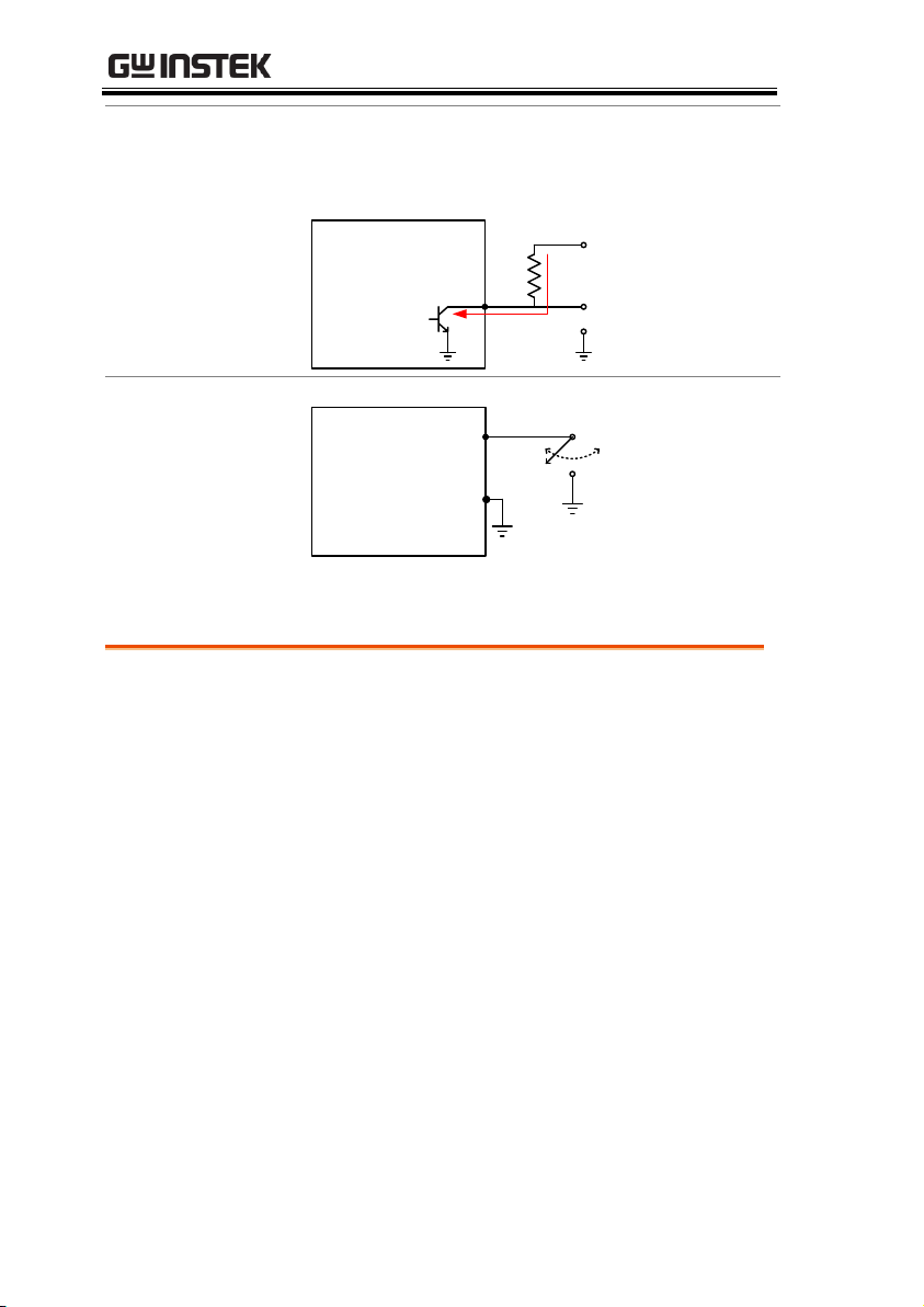
Wiring Diagram
Pins 1 ~ 4
Pins 1 ~ 4 are open-collector outputs, with a
max input of 30mA. All outputs are active low.
Pin 1-4
Vo
Imax = 30mA
Digital I/O
Terminal
Ext Vcc
Wiring Diagram
Trig In (Pin 5)
Pin 5
Pin 6
Trigger input
Digital I/O
Terminal
Normal Mode
Overview
The Normal Mode outputs the pass/fail results
of the Compare function. Each signal is an
active low signal. In addition an active low
pulse of approximately 5µs is output to indicate
the end of compare measurement (EOM).
When the input signal exceeds the high
threshold or the low threshold, the High Fail or
Low Fail pin is pulled low. When the signal
stays within the threshold levels, the Pass pin is
pulled low.
GDM-8351 User Manual
90
Page 91
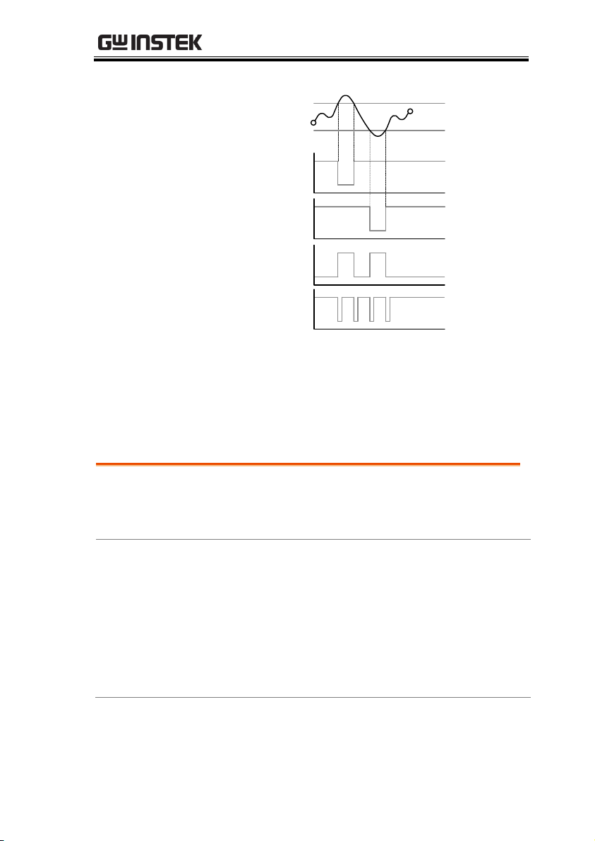
DIGITAL I/O
Timing Diagram
Low limit
High limit
P P P
EOM
H
L
Pin 3
PASS
Pin 4
EOM
Pin 1
HIGH FAIL
Pin 2
LOW FAIL
Pin 1-4
Output
Compare On
Compare Off
Related
Commands
DIGitalio:MODE {USER|NORM|?}
DIGitalio{X}:SETup {ON|OFF}
Procedure
1. Connect to the GDM-8351 remotely, see page 93
for remote control options.
2. Enable the user mode using the
DIGitalio:MODE command. See page 133.
3. Set the state of pins 1 ~ 4 using the
DIGitalio{X}:SETup command. See page 133.
User Mode
User mode can only used when using a remote control interface.
Likewise this mode can only be enabled or disabled via remote
control. Please see the digital I/O commands on page 133 for full
usage details.
91
Page 92

GDM-8351 User Manual
Example
DIG:MODE?
>NORM
DIG:MODE USER
DIG1:SETup ON
DIG2:SETup ON
DIG3:SETup ON
DIG4:SETup ON
DIG4:SETup?
>1
DIG:MODE NORM
Queries the mode.
Returns Norm mode.
Sets to USER mode.
Turns pin1 output on.
Turns pin2 output on.
Turns pin3 output on.
Turns pin4 output on.
Queries pin4 output state.
Returns pin4 output state.
Sets back to NORM mode.
92
Page 93

REMOTE CONTROL
Configure Remote Control Interface ................................. 94
USB Interface ............................................................. 94
Configure USB Interface ............................................ 94
Configure RS232 Interface ......................................... 95
Configure EOL Character ........................................... 97
Return to Local Control ................................................... 98
REMOTE CONTROL
This chapter describes basic configuration of IEEE488.2 based
remote control. For a command list, refer to the Command
Overview chapter on page 99.
93
Page 94
GDM-8351 User Manual
Note
*To use the TMC interface National
Instruments Measurement and Automation
Explorer can be used. This program is available
on the NI website, www.ni.com., via a search
for the VISA Run-time Engine page, or
“downloads” at the following URL,
http://www.ni.com/visa/
USB
Configuration
PC connector
Type A, host
DMM
connector
Rear panel Type B, slave
Speed
1.1/2.0 (full speed/high speed)
USB Class
TMC (USB T&M class), CDC
(Communications device class)
Hardware flow
control
Off
Data Bits
8
Stop bit
1
Configure Remote Control Interface
USB Interface
The USB device port on the rear panel is used for remote control.
The USB port can be configured as either a TMC or CDC interface.
When configured as a TMC interface, the DMM can be controlled
using National Instruments NI-Visa software*. NI-Visa version 3.0
and above supports USB TMC.
When configured to CDC, the USB port on the DMM will appear as
a virtual COM port to a connected PC. Any terminal program that
can communicate via a serial port can be used for remote control.
Before the DMM can be used for remote control using the CDC or
TMC USB class, install the appropriate CDC or TMC USB driver
included on the User Manual CD.
Configure USB Interface
94
Page 95
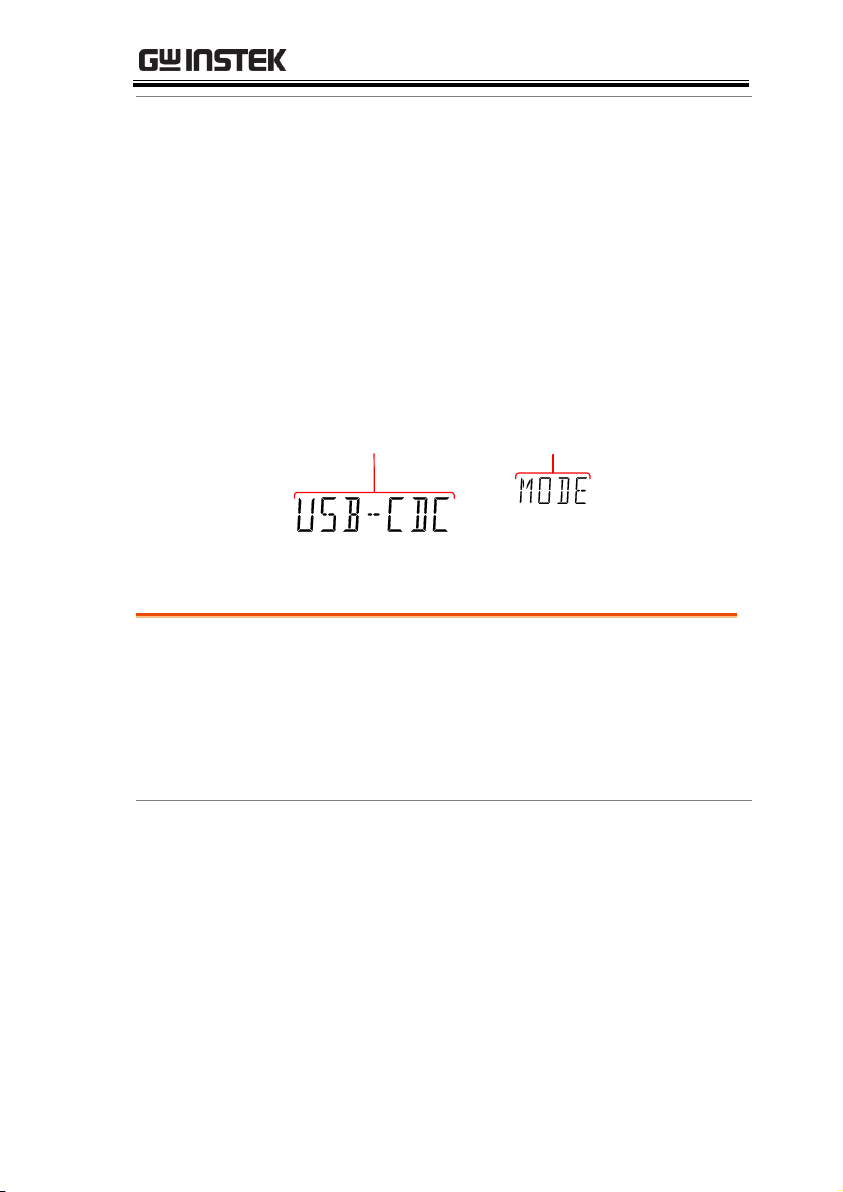
REMOTE CONTROL
Steps
1. Connect the USB cable to the rear panel type B
USB port.
2. Press MENU.
3. Go to I/O on level 1.
4. Go to USB on level 2.
5. Select USB-CDC or USB-TMC.
Display
REARGPIBCVCCSWEEPFILTRCLSTOCOMP2ND
dBmEXTSHIFTERRLIMITAUTOMATH4W2WDCAC
AVmm
HzWkM
WSFC
mdB
%
AVmm
HzWkM
WSFC
RMTMAXMINRELHOLDSMFAUTO4W2WDCAC
nμF
USB class
setting
USB menu
indicator
RS232
Configuration
Selectable Baud rate
9600, 19200, 38400, 57600,
115200
Parity
None
Hardware flow control
Off Data Bits
8
Stop bit
1
Steps
1. Connect the RS232 cable to the rear panel RS232
port.
Configure RS232 Interface
95
Page 96
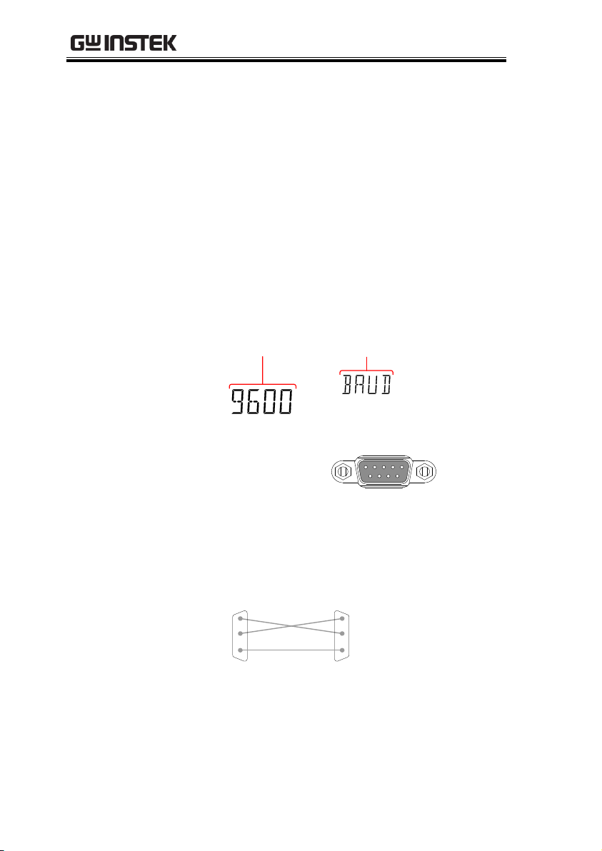
GDM-8351 User Manual
2. Press MENU.
3. Go to I/O on level 1.
4. Go to RS232 on level 2 and press Enter.
5. The baud rate settings appear. Set the baud
rate.
6. Press Enter to confirm the RS232 settings.
7. Press EXIT to exit from the System menu.
Display
REARGPIBCVCCSWEEPFILTRCLSTOCOMP2ND
dBmEXTSHIFTERRLIMITAUTOMATH4W2WDCAC
AVmm
HzWkM
WSFC
mdB
%
AVmm
HzWkM
WSFC
RMTMAXMINRELHOLDSMFAUTO4W2W
nμF
Baud rate
setting
BAUD menu
indicator
RS232 Pin
Assignments
Pin 2: RxD
Pin 3: TxD
Pin 5: GND
Pin 1, 4, 6 ~ 9: No
Connection
1
2345
6789
PC Connection
Use a Null Modem connection as shown in the
diagram below.
DMM PC
RxDPin2 RxD Pin2
GNDPin5 GND Pin5
TxD Pin3
TxDPin3
96
Page 97
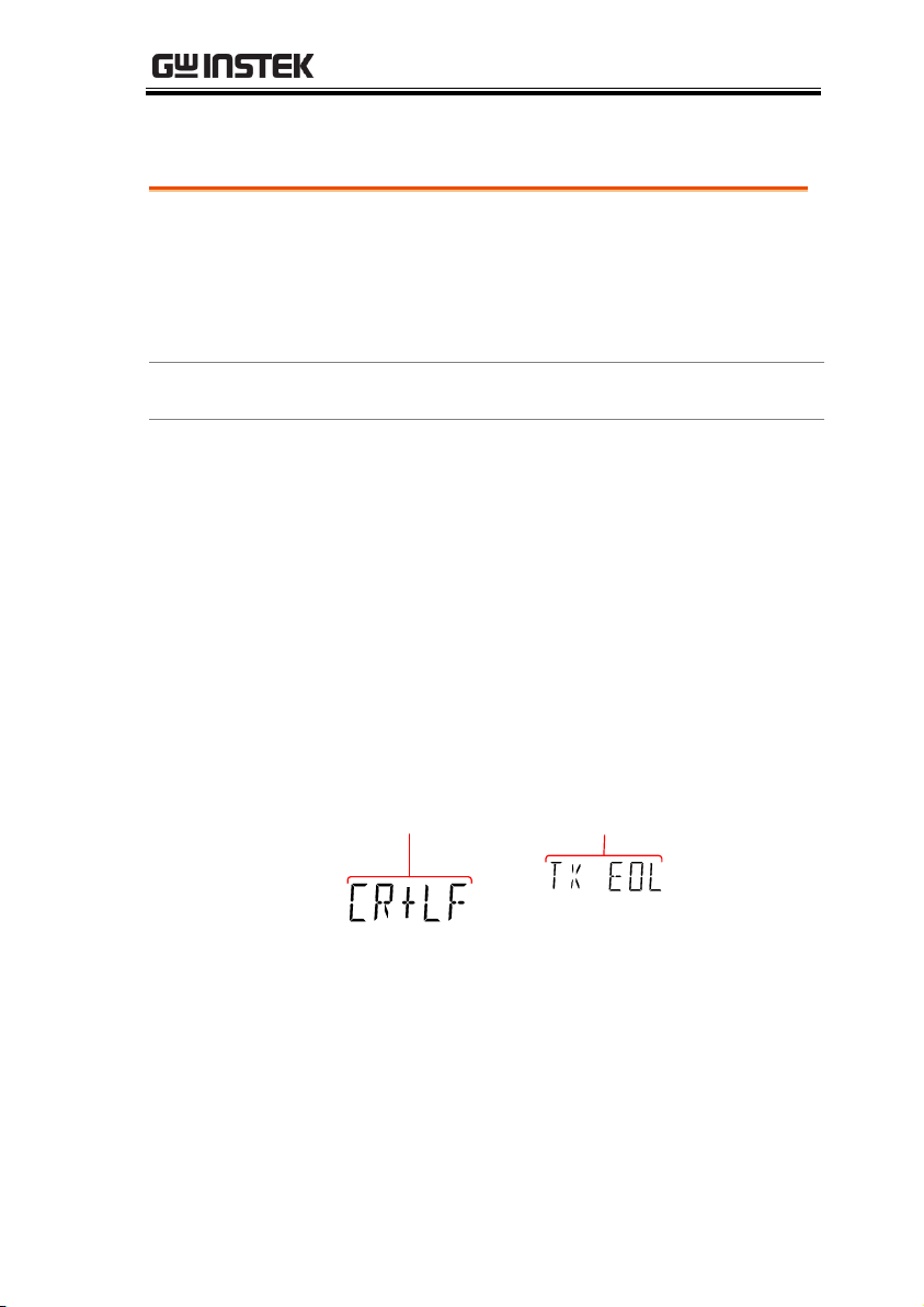
REMOTE CONTROL
Overview
The TX EOL settings set the EOL (end of line)
character for return messages. The EOL characters
that can be received from a PC include CR, LF,
CR+LF or LF+CR, with CR+LF being the most
common.
EOL Characters
CR+LF, LF+CR, CR, LF
Steps
1. Press MENU.
2. Go to TX TERM on level 1.
3. Go to TX EOL on level 2.
4. Set the EOL character.
5. Press Enter to confirm the EOL settings.
6. Press EXIT to exit from the System menu.
Display
REARGPIBCVCCSWEEPFILTRCLSTOCOMP2ND
dBmEXTSHIFTERRLIMITAUTOMATH4W2WDCAC
AVmm
HzWkM
WSFC
mdB
%
AVmm
HzWkM
WSFC
RMTMAXMINRELHOLDSMFAUTO4W2WDCAC
nμF
TX EOL
setting
TX EOL menu
indicator
Configure EOL Character
97
Page 98
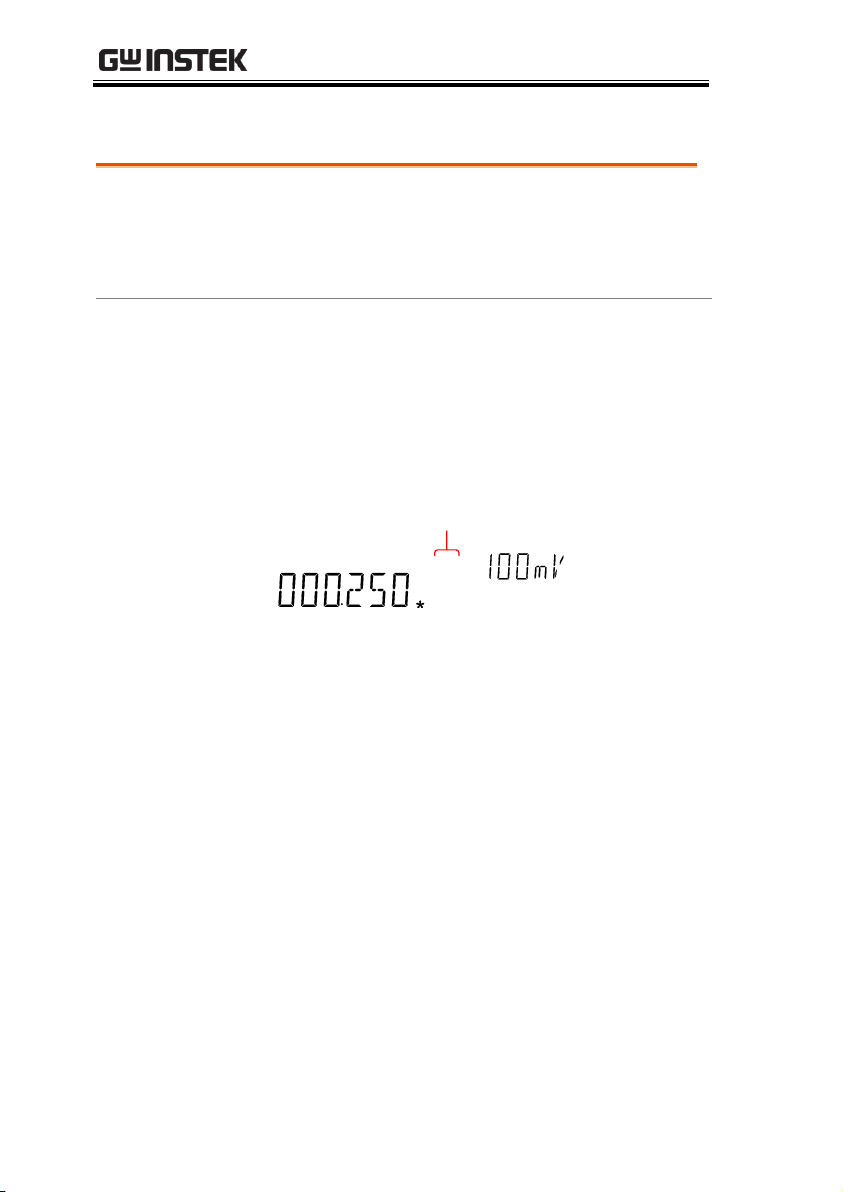
GDM-8351 User Manual
Background
When the unit is in remote control mode, the
RMT icon above the main display can be seen.
When this icon is not displayed, it indicates that
the unit is in local control mode.
Procedure
1. Press the LOCAL/2ND key when in remote
mode.
2. The unit will go back into local mode and the
RMT icon will turn off.
Display
REARGPIBCVCCSWEEPFILTRCLSTOCOMP2ND
dBmEXTSHIFTERRLIMITAUTOMATH4W2WDCAC
AVmm
HzWkM
WSFC
mdB
%
AVmm
HzWkM
WSFC
RMTMAXMINRELHOLDSMFAUTO4W2WDCAC
nμF
Remote control
indicator
Return to Local Control
98
Page 99

COMMAND OVERVIEW
Compatible
Standard
IEEE488.2
Partial compatibility
SCPI, 1994
Partial compatibility
Command
Structure
SCPI (Standard Commands for Programmable
Instruments) commands follow a tree-like
structure, organized into nodes. Each level of
the command tree is a node. Each keyword in a
SCPI command represents each node in the
command tree. Each keyword (node) of a SCPI
command is separated by a colon (:).
For example, the diagram below shows an SCPI
sub-structure and a command example.
:DCAC:DC :AC
CONFigure:VOLTage:DC
:VOLTage
CONFigure
COMMAND OVERVIEW
The Command overview chapter lists all programming commands
in functional order as well as alphabetical order. The command
syntax section shows you the basic syntax rules you have to apply
when using commands.
Command Syntax
99
Page 100
GDM-8351 User Manual
Command Types
There are a number of different instrument
commands and queries. A command sends
instructions or data to the unit and a query
receives data or status information from the
unit.
Command types
Simple
A single command
with/without a parameter
Example
CONFigure:VOLTage:DC
Query
A query is a simple or
compound command
followed by a question mark
(?). A parameter (data) is
returned.
Example
CONFigure:RANGe?
Command Forms
Commands and queries have two different
forms, long and short. The command syntax is
written with the short form of the command in
capitals and the remainder (long form) in lower
case.
The commands can be written either in capitals
or lower-case, just so long as the short or long
forms are complete. An incomplete command
will not be recognized.
Below are examples of correctly written
commands.
Long form
CONFigure:DIODe
CONFIGURE:DIODE
Configure:diode
100
 Loading...